EP2328480B1 - Low-cost device for c-scan photoacoustic imaging - Google Patents
Low-cost device for c-scan photoacoustic imaging Download PDFInfo
- Publication number
- EP2328480B1 EP2328480B1 EP09798815.8A EP09798815A EP2328480B1 EP 2328480 B1 EP2328480 B1 EP 2328480B1 EP 09798815 A EP09798815 A EP 09798815A EP 2328480 B1 EP2328480 B1 EP 2328480B1
- Authority
- EP
- European Patent Office
- Prior art keywords
- ultrasound
- acoustic
- time
- scan
- imaging
- Prior art date
- Legal status (The legal status is an assumption and is not a legal conclusion. Google has not performed a legal analysis and makes no representation as to the accuracy of the status listed.)
- Not-in-force
Links
Images


Classifications
-
- A—HUMAN NECESSITIES
- A61—MEDICAL OR VETERINARY SCIENCE; HYGIENE
- A61B—DIAGNOSIS; SURGERY; IDENTIFICATION
- A61B5/00—Measuring for diagnostic purposes; Identification of persons
- A61B5/0093—Detecting, measuring or recording by applying one single type of energy and measuring its conversion into another type of energy
- A61B5/0095—Detecting, measuring or recording by applying one single type of energy and measuring its conversion into another type of energy by applying light and detecting acoustic waves, i.e. photoacoustic measurements
-
- A—HUMAN NECESSITIES
- A61—MEDICAL OR VETERINARY SCIENCE; HYGIENE
- A61B—DIAGNOSIS; SURGERY; IDENTIFICATION
- A61B5/00—Measuring for diagnostic purposes; Identification of persons
- A61B5/0059—Measuring for diagnostic purposes; Identification of persons using light, e.g. diagnosis by transillumination, diascopy, fluorescence
- A61B5/0082—Measuring for diagnostic purposes; Identification of persons using light, e.g. diagnosis by transillumination, diascopy, fluorescence adapted for particular medical purposes
- A61B5/0091—Measuring for diagnostic purposes; Identification of persons using light, e.g. diagnosis by transillumination, diascopy, fluorescence adapted for particular medical purposes for mammography
-
- A—HUMAN NECESSITIES
- A61—MEDICAL OR VETERINARY SCIENCE; HYGIENE
- A61B—DIAGNOSIS; SURGERY; IDENTIFICATION
- A61B5/00—Measuring for diagnostic purposes; Identification of persons
- A61B5/41—Detecting, measuring or recording for evaluating the immune or lymphatic systems
- A61B5/414—Evaluating particular organs or parts of the immune or lymphatic systems
- A61B5/415—Evaluating particular organs or parts of the immune or lymphatic systems the glands, e.g. tonsils, adenoids or thymus
-
- A—HUMAN NECESSITIES
- A61—MEDICAL OR VETERINARY SCIENCE; HYGIENE
- A61B—DIAGNOSIS; SURGERY; IDENTIFICATION
- A61B5/00—Measuring for diagnostic purposes; Identification of persons
- A61B5/41—Detecting, measuring or recording for evaluating the immune or lymphatic systems
- A61B5/414—Evaluating particular organs or parts of the immune or lymphatic systems
- A61B5/418—Evaluating particular organs or parts of the immune or lymphatic systems lymph vessels, ducts or nodes
-
- A—HUMAN NECESSITIES
- A61—MEDICAL OR VETERINARY SCIENCE; HYGIENE
- A61B—DIAGNOSIS; SURGERY; IDENTIFICATION
- A61B5/00—Measuring for diagnostic purposes; Identification of persons
- A61B5/43—Detecting, measuring or recording for evaluating the reproductive systems
- A61B5/4306—Detecting, measuring or recording for evaluating the reproductive systems for evaluating the female reproductive systems, e.g. gynaecological evaluations
- A61B5/4312—Breast evaluation or disorder diagnosis
-
- A—HUMAN NECESSITIES
- A61—MEDICAL OR VETERINARY SCIENCE; HYGIENE
- A61B—DIAGNOSIS; SURGERY; IDENTIFICATION
- A61B5/00—Measuring for diagnostic purposes; Identification of persons
- A61B5/43—Detecting, measuring or recording for evaluating the reproductive systems
- A61B5/4306—Detecting, measuring or recording for evaluating the reproductive systems for evaluating the female reproductive systems, e.g. gynaecological evaluations
- A61B5/4318—Evaluation of the lower reproductive system
- A61B5/4337—Evaluation of the lower reproductive system of the vagina
-
- A—HUMAN NECESSITIES
- A61—MEDICAL OR VETERINARY SCIENCE; HYGIENE
- A61B—DIAGNOSIS; SURGERY; IDENTIFICATION
- A61B5/00—Measuring for diagnostic purposes; Identification of persons
- A61B5/43—Detecting, measuring or recording for evaluating the reproductive systems
- A61B5/4375—Detecting, measuring or recording for evaluating the reproductive systems for evaluating the male reproductive system
- A61B5/4381—Prostate evaluation or disorder diagnosis
-
- A—HUMAN NECESSITIES
- A61—MEDICAL OR VETERINARY SCIENCE; HYGIENE
- A61B—DIAGNOSIS; SURGERY; IDENTIFICATION
- A61B5/00—Measuring for diagnostic purposes; Identification of persons
- A61B5/45—For evaluating or diagnosing the musculoskeletal system or teeth
- A61B5/4538—Evaluating a particular part of the muscoloskeletal system or a particular medical condition
- A61B5/4571—Evaluating the hip
-
- A—HUMAN NECESSITIES
- A61—MEDICAL OR VETERINARY SCIENCE; HYGIENE
- A61B—DIAGNOSIS; SURGERY; IDENTIFICATION
- A61B8/00—Diagnosis using ultrasonic, sonic or infrasonic waves
- A61B8/44—Constructional features of the ultrasonic, sonic or infrasonic diagnostic device
- A61B8/4416—Constructional features of the ultrasonic, sonic or infrasonic diagnostic device related to combined acquisition of different diagnostic modalities, e.g. combination of ultrasound and X-ray acquisitions
-
- G—PHYSICS
- G01—MEASURING; TESTING
- G01S—RADIO DIRECTION-FINDING; RADIO NAVIGATION; DETERMINING DISTANCE OR VELOCITY BY USE OF RADIO WAVES; LOCATING OR PRESENCE-DETECTING BY USE OF THE REFLECTION OR RERADIATION OF RADIO WAVES; ANALOGOUS ARRANGEMENTS USING OTHER WAVES
- G01S7/00—Details of systems according to groups G01S13/00, G01S15/00, G01S17/00
- G01S7/52—Details of systems according to groups G01S13/00, G01S15/00, G01S17/00 of systems according to group G01S15/00
- G01S7/52017—Details of systems according to groups G01S13/00, G01S15/00, G01S17/00 of systems according to group G01S15/00 particularly adapted to short-range imaging
- G01S7/52053—Display arrangements
- G01S7/52057—Cathode ray tube displays
- G01S7/5206—Two-dimensional coordinated display of distance and direction; B-scan display
- G01S7/52061—Plan position indication (PPI display); C-scan display
Definitions
- the present invention is directed to imaging, e.g., of prostate tissue for detection of cancer and more particularly to photoacoustic imaging and ultrasound imaging to produce C-scans.
- Prostate cancer is the most prevalent newly diagnosed malignancy in men, second only to lung cancer in causing cancer-related deaths.
- Adenocarcinoma of the prostate is the most common malignancy in the Western world.
- Prostate cancer has been found incidentally in approximately 30% of autopsy specimens of men in their sixth decade. Seventy to 80% of patients who have prostate cancer are older than 65 years.
- Clinically localized disease is usually suspected based on an elevated prostate specific antigen (PSA) test or abnormal digital rectal exam (DRE), prompting transrectal ultrasound (TRUS) guided biopsy of the prostate for definitive diagnosis.
- PSA prostate specific antigen
- DRE abnormal digital rectal exam
- TRUS transrectal ultrasound
- TRUS is not reliable enough to be used solely as a template for biopsy.
- cancers that are not visible (isoechoic) on TRUS.
- accuracy of TRUS was only 52% due to false-positive findings encountered.
- Increased tumor vessels (angiogenesis) have been shown microscopically in prostate cancer compared with benign prostate tissue.
- Efficacy of color and power Doppler ultrasound has not been demonstrated, probably due to limited resolution and small flow velocities.
- Elasticity imaging with its many variants, is a new modality that is currently under extensive investigation. It is evident that given the limitations of the present diagnostic protocols, development of a new imaging modality that improves visualization and biopsy yield of prostate cancer would be beneficial. Furthermore, by making it cost effective, we can place it in the hands of primary care physicians, where it will serve its primary purpose as an adjunct to PSA, DRE, and TRUS.
- prostate cancer continues to be an area in which progress is needed despite recent advancements.
- Appropriate imaging of prostate cancer is a crucial component for diagnosing prostate cancer and its staging, in addition to PSA levels and DRE.
- the current state of prostate imaging for diagnosis of prostate cancer includes ultrasound, ultrasound-guided prostate biopsies, magnetic resonance imaging (MRI), and nuclear scinitigraphy. These modalities are helpful, but have drawbacks and limitations. MRI is expensive and not mobile. Nuclear scintillation is expensive, provides low resolution planar images, and there are problems with radiotracer excretion through the kidneys. Both these modalities are not available for general use.
- Ultrasound is not reliable enough to use solely as a template for diagnosing prostate cancer. It has two problems. First, in many cases prostate cancer appears as an isoechoic lesion (similar gray scale value as surrounding tissue) causing high miss rate ( Figure 10 ). Secondly, when it is visible (hyper or hypoechoic), it is not possible to say with certainty if it is cancer or benign because many other noncancer conditions such as prostate atrophy, inflammation of the prostate gland, and benign tumors may also look similar in appearance on ultrasound examination. A biopsy has to be performed on the suspect lesion for definitive diagnosis. Biopsies are uncomfortable and bleeding may result as a complication. Because of poor lesion detection, even the current prostate biopsy techniques miss approximately 30% of prostate cancer. Utility of color flow and power Doppler in conjunction with gray scale ultrasound has been explored, but not successfully. Therefore, there is an urgent need for a new imaging methodology that will be portable, economical to build, and will have widespread utility as a tool for primary screening and diagnosis of prostate cancer.
- Figure 10 shows transrectal sonography of the prostate gland with confirmed prostate cancer.
- Figure 10 demonstrates the grayscale appearance of the prostate gland (within arrows) in a patient with confirmed multiple zones of prostate cancer. As shown, the whole prostate gland appears heterogeneous and the prostate cancer zone is not identifiable because prostate cancer is similar in appearance to the surrounding prostate gland tissue. The arrowheads correspond to calcifications that can be seen in the prostate gland.
- US2005/018747 A1 discloses a non-invasive imaging system that applies ultrasound and stimulation light to a subject and uses a two dimensional array of transducer elements to pick up photo acoustic signals and reflected ultrasound that arise in response.
- Photoacoustic tomography imaging using a 4f acoustic lens and peak-hold technology by Yadong Wei et al is an article in Optics Express (14 April 2008, Vol. 16, No. 8, pages 5314-19 ) that describes a system in which a photoacoustic response is imaged using an acoustic lens and a one dimensional set (i.e. a line) of transducer elements.
- PA photoacoustic
- the invention provides a low-cost imaging technology that can take C-scan images of the prostate gland in real time based on the photoacoustic phenomenon.
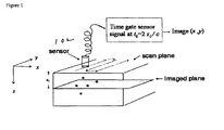
- C-scans are two-dimensional (2D) images produced by digitizing the point-by-point signal variation of an interrogating sensor while it is scanned over the surface. The x-y position of the sensor is recorded simultaneously with signal variations. A computer converts point-by-point data into an appropriate image.
- the photoacoustic effect is a phenomenon where acoustic waves are produced by absorbing points or objects of a medium that is irradiated with low-energy nanosecond (ns) pulses of laser light usually in near infrared region (NIR).
- NIR near infrared region
- the absorption of a short optical pulse causes localized heating and rapid thermal expansion, which generates thermoelastic stress waves (ultrasound waves).
- the ultrasound waves are generated instantaneously and simultaneously everywhere in a three-dimensional (3D) tissue volume irradiated by the laser pulse.
- the frequency content of the ultrasound waves generated is usually 1 to 20 MHz. It propagates in tissue as spherical waves in all directions. These waves will be referred to as the "PA signal" herein.
- the prostate gland will be stimulated with laser light, resulting in ultrasound waves (photoacoustic effect) that will be focused by an acoustic lens and captured by a specific 2D sensor array and subsequently displayed as a C-scan on a computer screen.
- the amplitude of the ultrasound waves generated by laser stimulation is proportional to the optical absorption of the tissue element at that spatial location. Variability in tissue absorption results in C-scan image contrast. For example, optical absorption in blood is 10-100 times higher than prostate tissue in the near infrared region. On this basis it is believed that the ultrasound signature in the C-scan image from prostate cancer will be different than the rest of the prostate gland.
- the key task in PA imaging is to determine the laser absorption distribution from the measured PA signal data.
- Most of the existing methodologies are slow (because the sensor acquires data point-by-point), computationally intensive (because computer based algorithms have to be used to reconstruct the image), suffer from poor SNR, and are expensive to develop and market.
- Lens focusing of sound energy generated with photoacoustic stimulation will improve the SNR and will project reconstructed coronal plane images (C-scan) of the prostate gland simultaneously.
- the imaging system can be lightweight, small in size, and therefore portable.
- the entire lens and sensor assembly can fit in a capsule no larger than 1.5x1x1 inches that can be used transrectally.
- a low power laser source and a computer monitor is all that will be required externally.
- CSPIP Low Cost Device for C-Scan Photoacoustic Imaging of Prostate Gland Cancer
- CSPIP has the potential for near real-time imaging (30 frames per second) unlike other methodologies, because they require some computational time for image reconstruction before it can be displayed.
- the lens forms a focused image that will be read out with the specially designed sensor at video rates (20-30 frames per second).
- CSPIP also offers the potential for full 3 dimensional imaging of the prostate through development of zoom acoustical lenses that will enable full resolution z-axis image cataloging and reconstruction as a solid. This will enhance the probability of early detection by enabling an arbitrary number of viewing angles of the prostate structure on the computer screen. Additionally this will also help in prostate cancer therapy planning and management (Radiotherapy and Brachytherapy-radioactive seed implantation).
- the invention has great potential to exploit high contrast in laser NIR absorption between blood and prostate tissue.
- Angiogenesis increased tumor blood vessels
- TRUS transrectal ultrasound
- CSPIP may also prove to be unique and better than Doppler ultrasound in detecting angiogenesis, because Doppler flow has poor detection sensitivity for slow flow velocities.
- contrast in the image depends on the blood concentration in cancer tissue and not on the blood flow velocity; therefore, it is expected to have better contrast and improved delineation of prostate cancer.
- CSPIP for prostate cancer detection we have proposed overcomes many shortcomings of the existing methodologies for imaging prostate cancer. It is a low cost, portable, non-echo based device that works on laser NIR stimulation followed by lens-based focusing of the PA signal. In CSPIP images are generated secondary to photoacoustic stimulation of the prostate gland. This system will have better contrast resolution than conventional ultrasound for detection of prostate cancer.
- the present invention differs from that of the Arnold reference at least in terms of time gating.
- the present invention uses time gating to select acoustic signals coming from a particular depth and thereby to provide a C-scan. Since Arnold does not use time gating, it cannot produce a C-scan.
- the PA signal at each pixel is proportional to the incident laser flux and the absorption coefficient of the tissue. Because the absorption coefficient of tissue depends on the laser wavelength, experiments will be performed to determine the best wavelength for optimal contrast in the PA image. Laser wavelengths to be used will be in the near infrared region.
- FIG. 2 shows the schematics for the experimental setup. Freshly excised prostate tissue slices of 2-4 mm will be immersed in a saline solution bath. A 10 ns laser pulse at a fixed wavelength ⁇ will be delivered to a small spot (approximate diameter 100 microns) via a fiber optic cable 204.
- ANSI American National Standards Institute
- maximum permissible exposure for human skin is 100 mJ/cm 2 .
- Laser flux will be kept below this limit at all times.
- a 20 MHz, 6 mm diameter circular disk transducer with a focal length of 12 mm will be used as a sensor for the PA signal.
- the transducer focal spot is expected to be 100 microns and will overlap with the laser spot. This overlap region is expected to set the spatial resolution for these experiments.
- the laser-transducer rigid assembly will be scanned in x-y and z directions with stepper motors under computer control. The step size may vary from 10-50 microns.
- the time-gated high frequency PA ultrasound signal will be digitized at 100 MHz and stored for further processing.
- the time gating can be performed in, or under the control of, a processor by any suitable technique.
- PA images will be created using several different data extraction schemes applied to the signal captured at each pixel location; they include (i) peak signal value in the time gate (ii) total energy in the time gate, and (iii) Amplitudes at several different temporal frequencies in the PA signal derived via its Fourier transform. These stage 1 experiments will enable determination of the optimal laser wavelength to be used for PA imaging.
- stage 2 The objective of stage 2 is to finalize the preliminary acoustic lens and hand-held device design generated by and to fabricate and test its ability to produce C-scan planar PA images of the prostate gland in-vitro.
- Figure 3 is a concept diagram that explains the innovative approach to PA imaging and the setup for the stage 2 experiments.
- a sensor located in plane A* can capture this energy as a focused image. It takes approximately 6.5 microseconds for ultrasound to travel 1 cm in tissue. It has been shown that the PA transient time signal is typically 1 microsecond or less in duration. Therefore, by time gating the total signal we can discard or minimize the signal coming from planes that are separated more than 1.5 mm from the chosen plane of focus. The assumption here is that the signal from all points in plane A comes to a focus in plane A* and its arrival time will be within the selected time gate width. The signal from all other planes will be discriminated primarily due to the time gate and secondarily due to the spatial spreading of its energy on this sensor plane that does not happen to be their corresponding conjugate image plane.
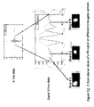
- Fig. 5A shows the setup.
- the image plane was scanned with a 1.5 mm diameter hydrophone.
- C-scan image plane was 10x25 pixels.
- the object was 0.2 mm lead pencil illuminated by a laser beam of 2 mm diameter.
- the laser generated pulses of wavelength 1064 nm with 10 ns pulse width.
- the point object was located at an object distance (OD) from the lens.
- the lens had a focal length of 27.5 mm.
- Hydrophone was located in the image plane at an image distance (ID) from the lens.
- An acoustic reflector was used to simulate first embodiment of prostate probe.
- Fig. 5B shows a single PA signal and several time gates chosen for C-Scan. C-Scan planar slices at different time gate centers are also depicted in the figure.
- Fig. 5C depicts a C-Scan image of the lead pencil embedded in a chicken breast tissue.
- lens design and fabrication will be performed. In vitro testing of the fabricated lens will be performed using phantoms and prostate gland tissue. Sensing of the PA signal will be done using a 0.1 mm diameter hydrophone. The tip of the hydrophone will be scanned in the image plane point-by-point with a pixel resolution of 100 microns. Lens aberrations, depth of field, in plane spatial resolution and resolution between C-scan planes, including signal to noise ratio are the quality metrics that will be tested. Based on preliminary study it is expected that the in plane and between the C-scan planes resolution of the proposed imaging system will be 250 microns or better.
- CMOS complementary metal oxide semiconductor
- ASIC action specific integrated circuits
- Piezoelectric materials such as PZT or PVDF will be laid on top of the CMOS as sensing layer. Sensing of the PA signal at each pixel will take place via the piezoelectric effect that generates charge proportional to the PA signal.
- CMOS technology with active pixel processing can integrate the charge within a selectable time gate, convert into voltage, and amplify it. The voltage can then be read out pixel by pixel at video rates with existing camera technology. The development work is expected to be centered on the piezoelectric sensor design and its integration into the CMOS technology.
- a system according to the invention can integrate a laser source, acoustic lens, and sensor components into a housing assembly that can be used for in vitro and in vivo testing.
- the laser stimulation module, lens system, and the ultrasound sensor will be housed in a capsule suitable for transrectal insertion to image prostate gland cancer.
- the capsule will be approximately 1.5 x 1 x 1 inches in size. Approximate weight of the capsule when fully assembled will be 12-14 ounces.
- Phantoms will be constructed with point and line targets made from high absorption coefficient material such as India ink or anticoagulated animal blood embedded in a low absorption background material.
- the objective is to map out the point-spread function of the CSPIP system at various points in the 3D space in front of the lens.
- a secondary objective is to determine the system signal sensitivity and signal-to-noise ratio (SNR). Linearity of the sensor and image contrast will be evaluated.
- SNR system signal sensitivity and signal-to-noise ratio
- 3D imaging of the excised prostate gland will be performed before the pathology study to determine the efficacy of PA imaging system to diagnose prostate cancer.
- An animal model for prostate cancer will be used for testing. Dogs will be injected with canine transmissible venereal sarcoma cell line that produces neoplasm in 15-40 days.
- TRUS and our prototype PA imaging device CSPIP will be used transrectally for imaging, comparison, and evaluation.
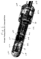
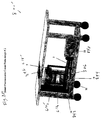
- the first preferred embodiment shown in Fig. 6 as 600, is a transrectal prostate probe.
- Components used for probe construction include: acoustic lens 306, acoustic reflector 608, acoustic window 610, acoustic propagation medium 612, fiber optic cable 614, collimator 616, beam expander 618, optical mirror 620, optical window 622, 2d sensor 102, air 626, probe body 628, and plane wave generator 630.
- the fiber optic cable is in communication with a laser source (not shown), which can be a photodiode or any other suitable source.
- a simple double-concave lens was designed and fabricated to be used as an acoustic lens.
- the material was chosen as Acrylic whose density is 1.19 g/cm 3 .
- the velocity of sound in acrylic medium is 2.75 mm/ ⁇ s and the acoustic impedance is about 3.26 MRayl.
- Other excellent candidate materials for acoustic lenses include RTV Silicone rubber (density: 1.49 g/cm 3 , velocity: 0.92mm/ ⁇ s and acoustic impedance: 1.37 MRayl) and agarose hydrogels (velocity of sound: 1.32 mm/ ⁇ s, acoustic impedance: 1.57 MRayl).
- the biconcave lens will converge the wavefront from the object plane (tissue) onto the image plane (sensor) with a magnification dictated by the object plane-lens and lens-image plane distances.
- the lens has a focal length of 27.5 mm and a diameter of 25 mm with a corresponding f number of 1.1. It was designed to produce best images when the object plane-lens distance and the corresponding lens-image plane distance were 55 mm with a resulting magnification of 1.
- Stainless steel was used as the acoustic reflector due to its excellent acoustic properties. It has an acoustic impedance of 46 MRayl which is very high compared to that of water. The velocity of sound through stainless steel medium is 5.79 mm/ ⁇ s. Stainless steel has a density of 7.89 g/cm 3 . The thickness of the acoustic reflector is 0.254mm.
- Low density polyethylene material was tested and used as acoustic window material. It has an acoustic impedance of 2.12 MRayl and a density of 0.92 g/cm 3 . Sound travels with a velocity of 1.85 mm/ ⁇ s through this material. The window has a thickness of is 0.793 mm and accounts for transmission of about 82.8% of the acoustic signals.
- Other materials that can be used as acoustic window are Hydrogels and TPX (Polymethylpentene). Hydrogels - Agarose gel samples have an acoustic impedance of 1.57 MRayl, very close to that of water. The longitudinal velocity of sound in these materials is about 1.32 mm/ ⁇ s. Polymethylpentene, commonly called TPX is another excellent material with a transparency of 91% in the visible spectrum and a density of 0.83 g/cm 3 . The speed of sound in TPX is 2.22 mm/ ⁇ s.
- Water was used as the ultrasonic wave propagation medium. Attenuation of ultrasound in water is 1.65 Np/m and the velocity of sound is 1.497 mm/ ⁇ s which is close to that of a biological tissue. Water has an acoustic impedance of 1.494 MRayl and a density of 0.998 gm/cm 3 . Mineral oil can also be used as an alternative for water for this purpose. Water was chosen over mineral oil due to its low attenuation coefficient compared to that of mineral oil which is 2.15 Np/m. The velocity of sound in mineral oil is 1.44 mm/ ⁇ s. Mineral oil has an acoustic impedance of 1.19 M Rayl and a density of 0.825 g/cm 3 . Valves 632 for water inlet/outlet were provided in the design that allows for regular maintenance. Any appropriate acoustic propagation medium with acoustic impedance close to 1 M Rayl can be used as appropriate.
- This lens technology can also be utilized for focusing reflected ultrasound signal similar to conventional ultrasound imaging.
- an input ultrasound source plane wave generator
- the laser source will be a tunable broadband laser with frequencies ranging from 500-1100 nm with a typical pulse width of 10 ns and 1-10 Hz pulse repetition frequency.
- the laser pulses will be delivered via a high quality fiber optic cable.
- the laser beam waist at the output of the fiber-optic cable-collimator assembly is typically 2 mm with intensity below 100 millijoules/cm 2 .
- Beam divergence will be controlled by an optical lens. This beam will be angled by a laser mirror such that the laser beam comes out from an optical window at grazing angle to the outer surface of the probe.
- the probe will have a diameter between 0.75 and 1.25 inches, and a length approximately 5 inches.
- the acoustic window will be aligned in front of the prostate when inserted into the rectum. With the help of acoustic coupling gel, the PA ultrasound waves generated in the prostate will enter through the acoustic window and guided towards the acoustic reflector.
- This reflector plate is made from stainless steel which has very high acoustic impedance material compared to water.
- the acoustic and optical chambers are separate and sealed.
- the acoustic chamber will contain any appropriate acoustic propagation medium with acoustic impedance close to 1 M Rayl, for example, water, as an acoustic propagation medium.
- This device will provide the C-scan images corresponding to a tissue thickness less than 1 mm, usually in the range of 700-900 microns over the entire length and width of the prostate by means of the 2d sensor.
- a FC-connectorized high power delivery fiber optic cable is used to deliver the pulsed high power laser beam from an external laser source. It features a pure silica core and a bonded hard polymer cladding. The fiber has a numerical aperture of 0.37 which allows for greater light coupling efficiencies. The fber's core diameter is 600 ⁇ m and cladding diameter is 630 ⁇ m. The maximum power density that the fiber can withstand is 100 KW/cm 2. This fiber is suitable for use in the 500 nm to 1100 nm wavelength range.
- An FC-connectorized fiber optic collimator is used to collimate the diverging output laser beam from the fiber.
- the numerical aperture of the collimator is 0.25, with a full beam divergence of 0.048° and 1/e 2 output beam diameter of 2 mm. It has a focal length of 11 mm.
- Cylindrical and spherical plano-concave lenses are used as beam expanders depending on the application to diverge the collimated beam. Cylindrical lenses provide four times higher laser exposure on the tissue compared to spherical lenses. The lenses have a focal length of -15 mm which facilitates in illuminating the tissue volume over a width of about 1 cm. The size of the cylindrical lens was 10 mm x 12 mm with a clear aperture greater than 90% of surface dimensions. The spherical lens has a diameter of 12.7 mm with a clear aperture greater than 90% of its diameter.
- a laser mirror of diameter 12.7 mm and thickness 6 mm is used to reflect the diverging beam resulting from the optical lens onto the tissue. It has a high damage threshold of 5 J/cm 2 for a 10 ns pulse. Reflectivity of the mirror is greater than 99.7% with a clear aperture greater than 80% of diameter.
- a BK7 1/4 wave laser line window of dimensions 35 mm x 15 mm and thickness 3 mm was used as an optical window to allow light propagation onto the tissue.
- a two-dimensional PZT sensor array will be designed and fabricated with on-pixel processing capabilities that can provide C-scan images in real time.
- the frequency bandwidth of the sensor will be 2-15 MHz.
- the sensor will provide C-scan images with slice thickness in the range of 700 to 900 microns.
- action specific integrated circuits will be employed to read the voltage at each pixel, amplify, convert it from analog to digital format and read out on the display.
- the laser light beam is allowed to propagate through air before passing out of the optical window. It also ensures that the sensor's backend electronics are insulated from water (or whatever acoustic propagation medium is used).
- the probe body is made of a material called watershed XC11122. Its properties mimic traditional engineering plastics including ABS and PBT.
- the size of the probe depends mainly on the application. In case of the prostate, it is designed as side-fire probe, and in case of applications like breast, skin, thyroid or transvaginal imaging, it will be designed as end-fire probe or its variables.
- a high bandwidth ultrasonic transducer of 5 MHz nominal center frequency is used as a plane wave generator whose electrical impedance will be well matched to conventional ultrasound pulsar/receivers.
- the transducer will have a low Q-factor (air-backed into PMMA) and conforms perfectly to the probe's cylindrical surface.
- Typical thickness of this plane wave generator would be 110 microns (dual layer) with a low electrical impedance of 30 to 100 ohms. It will be bonded with epoxy resin or a transfer adhesive to acoustic window material and then be used.
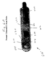
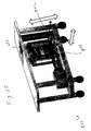
- FIG. 6A and 6B A variation of the first preferred embodiment will be described with reference to Figs. 6A and 6B .
- the variation, shown in Figs. 6A and 6B as 600', uses ultrasound only rather than both ultrasound and the photoacoustic effect and is constructed like the previously described probe 600, except for the omission of elements relating solely to the photoacoustic effect and for any differences described herein.
- the device 600' will facilitate the definitive detection of prostate cancer and generates C-scan multiplanar images.
- An input ultrasound source plane wave generator
- the probe will have a diameter between 0.75 and 1 inches, and a length approximately 5 inches.
- the acoustic window will be aligned in front of the prostate when inserted into the rectum. With the help of acoustic coupling gel, the ultrasound waves reflected from the prostate will enter through the acoustic window and guided towards the acoustic reflector.
- This reflector plate is made from stainless steel which has very high acoustic impedance material compared to water. Water is used as acoustic propagation medium because of its low ultrasound attenuation coefficient compared to mineral oil. Any appropriate acoustic propagation medium with acoustic impedance close to 1 M Rayl can be used. This device will provide the C-scan multiplanar images of the prostate gland.
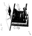
- FIG. 7 Another preferred embodiment, shown in Fig. 7 as 700, can be used to evaluate prostate cancer (or cancer of any other organ) in vitro. It is constructed like the first preferred embodiment, except as described below.
- pathologists When pathologists receive a freshly excised sample with cancer, they are uncertain of the exact location of cancer. In order to determine its location, the specimen will be sliced and visually inspected by naked eye. If any abnormalities are present, the specimens will be examined through histopathology procedure.
- This device will facilitate the detection of cancer in the tissue for e.g., prostate gland which has been removed by surgery thus aiding the pathologist in locating the cancer. It provides the depth and location of the cancer by calculating all the foci (since the prostate is multifocal) within the prostate gland. This procedure saves a lot of time and will help in appropriate staging of prostate cancer.
- This device can be used not only for prostate but also for detecting cancer in any other organ of the body such as ovary, testis, uterus, kidney etc. that has been submitted to the pathologist for evaluation. This device will provide the C-scan images corresponding to a tissue thickness less than 1 mm, usually in the range of 700-900 microns over the entire length and width of the prostate.
- the specimen Sp is usually setup in a water bath 734 to ensure maximum acoustic matching between the tissue and the medium. Any appropriate acoustic propagation medium with acoustic impedance close to 1 M Rayl can be used instead.
- the acoustic window will be aligned in front of the prostate during the examination. With the help of acoustic coupling gel 733 and acoustic windows 735, the PA ultrasound waves generated in the prostate will enter through the acoustic window and focused onto the sensor by means of the acoustic lens. Water (or other acoustic propagation medium, as noted) is filled inside the probe which acts as the acoustic propagation medium. Scanning optics 736 allow scanning of the light over the sample.
- a third preferred embodiment, shown in Fig. 8 as 800, can be used for breast imaging. It is constructed like the first and second preferred embodiments, except as described below.
- Breast cancer is the highest incident cancer among the women worldwide. Although the techniques such as x-ray mammography, ultrasound imaging and biopsy are currently used to detect and diagnose breast cancers, they all suffer from drawbacks including high rate of missed positives, use of ionizing radiation and patient discomfort.
- the third preferred embodiment generates C-scan planar images, depicting the entire breast in sequential transverse planes. Focusing of each plane happens in real time with the help of the acoustic lens. The lens will be large enough for the photoacoustic signals generated from the entire breast volume to propagate towards the receiver. A breast holder 837 holds the breast Br.
- a first variation of the third preferred embodiment is shown in Figs. 8A-8D as 800'.
- the first variation uses the photoacoustic effect only and can be constructed like the system 800 according to the third preferred embodiment, except for the omission of the plane wave generator and any changes set forth herein.
- the device will facilitate the definitive detection of breast cancer and generates C-scan multiplanar images of the breast.
- the device includes a table that can be built into a hospital bed. It has a vent (sliding door 846) on the top to allow free hanging of the breast that needs to be imaged. During the examination, only one of the breasts (either left or right) will be compressed with a compression plate and the other one that needs to be imaged will be allowed to protrude through the vent provided.
- the probe will have a diameter between 3 and 5 inches, and a length approximately 3 inches, and it includes an acoustic window that is curved inwards to ensure matching between the breast surface and the acoustic propagation medium (any appropriate acoustic propagation medium with acoustic impedance close to 1 M Rayl, for example, water) inside the probe.
- This probe which consists of acoustic lens, water and the sensor will be mounted onto a translation stage that can move horizontally from left to right depending on the side being imaged. Also, this entire stage is provided a vertical translation movement to make sure that the probe is in contact with the breast before the exam is started.
- the lens will be large enough for the photoacoustic signals generated from the entire breast volume to propagate towards the sensor.
- the laser source will be a tunable broadband laser with frequencies ranging from 500-1100 nm with a typical pulse width of 10 ns and 1-10 Hz pulse repetition frequency.
- the laser pulses will be delivered via a bundle of high quality fiber optic cables.
- the laser beam waist at the output of the fiber-optic cable is typically 2 mm with intensity below 100 millijoules/cm 2 .
- the fiber-optic cables are arranged in a circular fashion and are equipped into a ring around the breast.
- the fiber-optic cables are terminated onto compound lens-beam expanders which can move back and forth for controlled illumination of the breast.
- the laser beams irradiate the breast from all the directions so that the entire breast will become the source of photoacoustic signals.
- acoustic coupling gel With the help of acoustic coupling gel, the photoacoustic waves generated in the breast enter through the acoustic window and are focused by the acoustic lens onto the sensor and the C-scan images are generated.
- Water is used as the acoustic propagation medium. Any appropriate acoustic propagation medium with acoustic impedance close to 1 M Rayl could be used instead.
- This device will provide the C-scan images corresponding to a tissue thickness less than 1 mm, usually in the range of 700-900 microns over the entire length and width of breast by means of the 2d sensor.
- the acoustic lens will converge the wavefront from the object plane (tissue) onto the image plane (sensor) with a magnification dictated by the object plane-lens and lens-image plane distances. It produces best images when the object plane-lens distance and the corresponding lens-image plane distance are at a distance of twice the lens-focal length with a resulting magnification of 1.
- the lens will be large enough to ensure that the acoustic signals from the entire breast are received by the sensor.
- the shape of the acoustic window 610' in this case will follow a concave pattern to ensure maximum acoustic match between the breast and the acoustic propagation medium (any appropriate acoustic propagation medium with acoustic impedance close to 1 M Rayl, for example, water) inside the probe so that the signal-to -noise ratio is maximized.
- acoustic propagation medium any appropriate acoustic propagation medium with acoustic impedance close to 1 M Rayl, for example, water
- a group of high power delivery fiber optic cables will be used to deliver the pulsed high power laser beam from an external laser source. They feature a pure silica core and a bonded hard polymer cladding. The fibers have a larger numerical aperture that allows for greater light coupling efficiencies. The fiber's core diameter is typically 600 ⁇ m and cladding diameter is 630 ⁇ m. The maximum power density that the fiber can withstand is 100 KW/cm 2 . These fibers will be suitable for use in 500 nm to 1100 nm wavelength range.
- Cylindrical and spherical plano-concave lenses will be used as beam expanders 618' to diverge the light beam coming out of the fibers. These lenses will also allow focusing like camera-zoom lenses. Depending on the desired area to be imaged, the area over which the light is irradiated will be controlled with the aid of them. Cylindrical lenses provide four times higher laser exposure on the tissue compared to spherical lenses. The lenses have a focal length of-15 mm which facilitates in illuminating the tissue volume over a width of about 1 cm. The lenses have their clear apertures greater than 90% of surface dimensions.
- a high energy broadband tunable pulsed laser source 840 with a typical pulse repetition rate of 10 Hz and pulse duration of 10 ns will be employed as the external laser source to generate laser beam of desired size.
- the exposure energy will be lower than the maximum permissible exposure limits set by ANSI 136.1 standards for the human tissue.
- a Ti:Sapphire laser coupled to Nd:YAG laser through a frequency doubler will provide a wide range of wavelengths that are suitable for photoacoustic imaging.
- the first one, 842 is for vertical movement of the acoustic lens-sensor configuration along with the circular ring with fiber optic cables to adjust according to the location of the breast.
- the second one, 844 is for horizontal movement of the detector configuration (along with the lens and the ring with fiber optic cables) to accommodate the left or right breast, which may be accessed through a sliding door 846.
- a second variation of the third preferred embodiment, shown in Fig. 8E as 800", is used for breast ultrasound. It can be constructed like the third preferred embodiment 800, except for the omission of the elements concerned only with the photoacoustic effect and for any differences described herein.
- the device 800" will facilitate the definitive detection of breast cancer and generates C-scan multiplanar images of the breast.
- An input ultrasound source plane wave generator
- Focusing of each plane happens in real time with the help of the acoustic lens.
- the lens will be large enough for focusing the ultrasound signals reflected from the entire breast volume to propagate towards the receiver.
- the breast is compresses during the examination and the C-scan images over the entire volume of the breast are produced by the device.
- the probe including the acoustic window, acoustic lens and the 2d sensor is brought in contact with the acoustically transparent compression plate from the bottom.
- the probe will have a diameter between 3 and 5 inches, and a length approximately 3 inches.
- acoustic coupling gel when the plane wave generator produces the ultrasound waves, they get reflected form the breast and propagate back through the acoustic window, and will be focused onto the image plane (2d sensor) with the help of an acoustic lens.
- Water is used as acoustic propagation medium. Any appropriate acoustic propagation medium with acoustic impedance close to 1 M Rayl could be used instead.
- This device will provide the C-scan images corresponding to a tissue thickness less than 1 mm, usually in the range of 700-900 microns over the entire length and width of breast by means of the 2d sensor.
- the fourth preferred embodiment shown in Fig. 9 as 900, is a transvaginal photoacoustic and ultrasound C-scan probe. It is constructed like the first through third preferred embodiments, except as described below.
- an appropriate material will be used that allows both the optical beam and ultrasound waves with minimal transmission losses.
- transvaginal ultrasound is used to diagnose the cause of certain types of infertility, pelvic pain, abnormal bleeding, and menstrual problems. It is often used to show the lining of the uterus. Though the test may reveal certain conditions such as pelvic infection or monitor the growth of the fetus during the pregnancy, it suffers from false positive results in detecting ovarian cysts, ovarian tumors and the cancers of the uterus, vagina and other pelvic structures.
- the fourth preferred embodiment generates C-scan planar images, depicting the entire uterus or ovaries in sequential planes. Focusing of each plane happens in real time with the help of the acoustic lens.
- the tip of the probe is made optically as well as acoustically transparent with the help of an opto-acoustic window.
- the delivery of light through two fiber-optic cables ensures that more area is exposed to light thus resulting in the generation of photoacoustic signals from a larger area.
- the probe will have a diameter between 0.75 and 1 inches, and a length approximately 5 inches.
- the opto-acoustic window will be aligned in front of the uterus when inserted into the vagina. With the help of acoustic coupling gel, the PA ultrasound waves generated in the tissue will enter through the acoustic window and focused onto the sensor by means of acoustic lens.
Landscapes
- Health & Medical Sciences (AREA)
- Life Sciences & Earth Sciences (AREA)
- Physics & Mathematics (AREA)
- Veterinary Medicine (AREA)
- Surgery (AREA)
- Engineering & Computer Science (AREA)
- Biomedical Technology (AREA)
- Heart & Thoracic Surgery (AREA)
- Medical Informatics (AREA)
- Molecular Biology (AREA)
- Pathology (AREA)
- Animal Behavior & Ethology (AREA)
- General Health & Medical Sciences (AREA)
- Public Health (AREA)
- Biophysics (AREA)
- Reproductive Health (AREA)
- Gynecology & Obstetrics (AREA)
- Immunology (AREA)
- Vascular Medicine (AREA)
- Acoustics & Sound (AREA)
- Endocrinology (AREA)
- Physical Education & Sports Medicine (AREA)
- Dentistry (AREA)
- Oral & Maxillofacial Surgery (AREA)
- Orthopedic Medicine & Surgery (AREA)
- Rheumatology (AREA)
- Ultra Sonic Daignosis Equipment (AREA)
- Investigating Or Analyzing Materials By The Use Of Ultrasonic Waves (AREA)
Description
- The present invention is directed to imaging, e.g., of prostate tissue for detection of cancer and more particularly to photoacoustic imaging and ultrasound imaging to produce C-scans.
- Prostate cancer is the most prevalent newly diagnosed malignancy in men, second only to lung cancer in causing cancer-related deaths. Adenocarcinoma of the prostate is the most common malignancy in the Western world. There were a projected 218,890 new cases of prostate cancer diagnosed in the United States in 2007, with an estimated 27,050 deaths. As men age, the risk of developing prostate cancer increases. Prostate cancer has been found incidentally in approximately 30% of autopsy specimens of men in their sixth decade. Seventy to 80% of patients who have prostate cancer are older than 65 years. Clinically localized disease is usually suspected based on an elevated prostate specific antigen (PSA) test or abnormal digital rectal exam (DRE), prompting transrectal ultrasound (TRUS) guided biopsy of the prostate for definitive diagnosis. TRUS however, is not reliable enough to be used solely as a template for biopsy. There are cancers that are not visible (isoechoic) on TRUS. Furthermore, in PSA screened populations, the accuracy of TRUS was only 52% due to false-positive findings encountered. Increased tumor vessels (angiogenesis) have been shown microscopically in prostate cancer compared with benign prostate tissue. Efficacy of color and power Doppler ultrasound has not been demonstrated, probably due to limited resolution and small flow velocities. Elasticity imaging, with its many variants, is a new modality that is currently under extensive investigation. It is evident that given the limitations of the present diagnostic protocols, development of a new imaging modality that improves visualization and biopsy yield of prostate cancer would be beneficial. Furthermore, by making it cost effective, we can place it in the hands of primary care physicians, where it will serve its primary purpose as an adjunct to PSA, DRE, and TRUS.
- The need for tumor visualization is equally critical in the treatment of localized prostate cancer disease. Existing therapeutic strategies, namely external beam radiation, prostate brachytherapy, cryosurgery, and watchful waiting, all will benefit significantly from the development of a new modality that promises better tumor contrast. Thus, prostate cancer continues to be an area in which progress is needed despite recent advancements.
- Appropriate imaging of prostate cancer is a crucial component for diagnosing prostate cancer and its staging, in addition to PSA levels and DRE. The current state of prostate imaging for diagnosis of prostate cancer includes ultrasound, ultrasound-guided prostate biopsies, magnetic resonance imaging (MRI), and nuclear scinitigraphy. These modalities are helpful, but have drawbacks and limitations. MRI is expensive and not mobile. Nuclear scintillation is expensive, provides low resolution planar images, and there are problems with radiotracer excretion through the kidneys. Both these modalities are not available for general use.
- Ultrasound is not reliable enough to use solely as a template for diagnosing prostate cancer. It has two problems. First, in many cases prostate cancer appears as an isoechoic lesion (similar gray scale value as surrounding tissue) causing high miss rate (
Figure 10 ). Secondly, when it is visible (hyper or hypoechoic), it is not possible to say with certainty if it is cancer or benign because many other noncancer conditions such as prostate atrophy, inflammation of the prostate gland, and benign tumors may also look similar in appearance on ultrasound examination. A biopsy has to be performed on the suspect lesion for definitive diagnosis. Biopsies are uncomfortable and bleeding may result as a complication. Because of poor lesion detection, even the current prostate biopsy techniques miss approximately 30% of prostate cancer. Utility of color flow and power Doppler in conjunction with gray scale ultrasound has been explored, but not successfully. Therefore, there is an urgent need for a new imaging methodology that will be portable, economical to build, and will have widespread utility as a tool for primary screening and diagnosis of prostate cancer. -
Figure 10 shows transrectal sonography of the prostate gland with confirmed prostate cancer.Figure 10 demonstrates the grayscale appearance of the prostate gland (within arrows) in a patient with confirmed multiple zones of prostate cancer. As shown, the whole prostate gland appears heterogeneous and the prostate cancer zone is not identifiable because prostate cancer is similar in appearance to the surrounding prostate gland tissue. The arrowheads correspond to calcifications that can be seen in the prostate gland. - U.S. Patent Application Publication No.
US 2009/0024038 A1 to Arnold teaches an acoustic imaging probe incorporating photoacoustic excitation, but does not overcome all of the above-noted deficiencies of the prior art. -
US2005/018747 A1 discloses a non-invasive imaging system that applies ultrasound and stimulation light to a subject and uses a two dimensional array of transducer elements to pick up photo acoustic signals and reflected ultrasound that arise in response. - "Photoacoustic tomography imaging using a 4f acoustic lens and peak-hold technology by Yadong Wei et al is an article in Optics Express (14 April 2008, Vol. 16, No. 8, pages 5314-19) that describes a system in which a photoacoustic response is imaged using an acoustic lens and a one dimensional set (i.e. a line) of transducer elements.
- The invention is defined by the appended claims, to which reference should now be made.
- It is therefore an aim for certain embodiments of the invention to provide photoacoustic (PA) imaging technology for the betterment of prostate cancer diagnosis and disease management.
- It is a further aim for certain embodiments the invention to provide a low-cost imaging technology that can take C-scan images of the prostate gland in real time based on the photoacoustic phenomenon.
- It is a yet further aim for certain embodiments of the invention to provide a low-cost imaging technology that can take C-scan images based on both the photoacoustic phenomenon and ultrasound so that the resulting images are automatically coregistered.
- It is a still further aim for embodiments of the invention to provide such a low-cost imaging technology whose applicability is not limited to prostate cancer, but instead can be extended to other organs for cancer detection such as breast cancer, uterine cancer, ovarian cancer, thyroid cancer, etc.
- To enable embodiments of the invention to achieve the above and other aims, the present invention is directed to an imaging technology combining C-scans with the photoacoustic effect. C-scans are two-dimensional (2D) images produced by digitizing the point-by-point signal variation of an interrogating sensor while it is scanned over the surface. The x-y position of the sensor is recorded simultaneously with signal variations. A computer converts point-by-point data into an appropriate image.
- The photoacoustic effect is a phenomenon where acoustic waves are produced by absorbing points or objects of a medium that is irradiated with low-energy nanosecond (ns) pulses of laser light usually in near infrared region (NIR). The absorption of a short optical pulse causes localized heating and rapid thermal expansion, which generates thermoelastic stress waves (ultrasound waves). The ultrasound waves are generated instantaneously and simultaneously everywhere in a three-dimensional (3D) tissue volume irradiated by the laser pulse. The frequency content of the ultrasound waves generated is usually 1 to 20 MHz. It propagates in tissue as spherical waves in all directions. These waves will be referred to as the "PA signal" herein.
- In certain embodiments of the invention, the prostate gland will be stimulated with laser light, resulting in ultrasound waves (photoacoustic effect) that will be focused by an acoustic lens and captured by a specific 2D sensor array and subsequently displayed as a C-scan on a computer screen. The amplitude of the ultrasound waves generated by laser stimulation is proportional to the optical absorption of the tissue element at that spatial location. Variability in tissue absorption results in C-scan image contrast. For example, optical absorption in blood is 10-100 times higher than prostate tissue in the near infrared region. On this basis it is believed that the ultrasound signature in the C-scan image from prostate cancer will be different than the rest of the prostate gland. It is non echo-based imaging because there is no transmitted ultrasound pulse and contrast in the image does not depend on the echogenicity. Therefore, it is more advantageous than conventional ultrasound because it is based on a different contrast mechanism. It may be considered a hybrid imaging technique, combining ultrasound for imaging and photoacoustic effect for contrast.
- The key task in PA imaging is to determine the laser absorption distribution from the measured PA signal data. Most of the existing methodologies are slow (because the sensor acquires data point-by-point), computationally intensive (because computer based algorithms have to be used to reconstruct the image), suffer from poor SNR, and are expensive to develop and market. Lens focusing of sound energy generated with photoacoustic stimulation will improve the SNR and will project reconstructed coronal plane images (C-scan) of the prostate gland simultaneously.
- The imaging system can be lightweight, small in size, and therefore portable. The entire lens and sensor assembly can fit in a capsule no larger than 1.5x1x1 inches that can be used transrectally. A low power laser source and a computer monitor is all that will be required externally.
- The electrical power consumption of the invention, at least in an embodiment called "Low Cost Device for C-Scan Photoacoustic Imaging of Prostate Gland Cancer" (CSPIP), will be very low because, unlike other existing methodologies under development, lens focusing does not require any electrical power. CSPIP has the potential for near real-time imaging (30 frames per second) unlike other methodologies, because they require some computational time for image reconstruction before it can be displayed. In CSPIP the lens forms a focused image that will be read out with the specially designed sensor at video rates (20-30 frames per second). CSPIP also offers the potential for full 3 dimensional imaging of the prostate through development of zoom acoustical lenses that will enable full resolution z-axis image cataloging and reconstruction as a solid. This will enhance the probability of early detection by enabling an arbitrary number of viewing angles of the prostate structure on the computer screen. Additionally this will also help in prostate cancer therapy planning and management (Radiotherapy and Brachytherapy-radioactive seed implantation).
- The invention has great potential to exploit high contrast in laser NIR absorption between blood and prostate tissue. Angiogenesis (increased tumor blood vessels) of prostate cancer is well established. Therefore, it is believed that we will be able to visualize the cancer and its size better with CSPIP than with transrectal ultrasound (TRUS), because the latter is based only on the echogenicity of cancer tissue.
- CSPIP may also prove to be unique and better than Doppler ultrasound in detecting angiogenesis, because Doppler flow has poor detection sensitivity for slow flow velocities. In CSPIP, contrast in the image depends on the blood concentration in cancer tissue and not on the blood flow velocity; therefore, it is expected to have better contrast and improved delineation of prostate cancer.
- In summary, CSPIP for prostate cancer detection we have proposed overcomes many shortcomings of the existing methodologies for imaging prostate cancer. It is a low cost, portable, non-echo based device that works on laser NIR stimulation followed by lens-based focusing of the PA signal. In CSPIP images are generated secondary to photoacoustic stimulation of the prostate gland. This system will have better contrast resolution than conventional ultrasound for detection of prostate cancer.
- The present invention differs from that of the Arnold reference at least in terms of time gating. The present invention uses time gating to select acoustic signals coming from a particular depth and thereby to provide a C-scan. Since Arnold does not use time gating, it cannot produce a C-scan.
- Preferred embodiments of the present invention will be set forth in detail with respect to the drawings, in which:
-
Fig. 1 is a concept diagram to illustrate the concept of C-scan; -
Fig. 2 is a diagram of a stage-1 experiment; -
Fig. 3 is a diagram of a stage-2 experiment; -
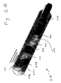
Fig. 4 shows a set of C-scan photoacoustic images of a pencil exposed by a 2 mm laser beam; -
Fig. 5A shows a lens-based C-scan photoacoustic imaging breadboard proof of concept; -
Fig. 5B shows C-scan planar slices of a photoacoustic signal at different time gate centers; -
Fig. 5C shows a C-scan image of the lead pencil embedded in chicken breast tissue; -
Fig. 6 is a diagram of a probe according to the first preferred embodiment; -
Figs 6A and6B are diagrams of a variation of the probe ofFig. 6 -
Fig. 7 is a diagram of a system according to the second preferred embodiment; -
Fig. 8 is a diagram of a system according to the third preferred embodiment; -
Figs. 8A-8D are diagrams of a system according to a first variation of the third preferred embodiment; -
Fig. 8E is a diagram of a system according to a second variation of the third preferred embodiment; -
Fig. 9 is a diagram of a system according to the fourth preferred embodiment; and -
Fig. 10 is a traditional transrectal sonogram of a prostate with confirmed prostate cancer. - Preferred embodiments of the present invention will be set forth in detail with reference to the drawings, in which like reference numerals refer to like elements or steps throughout.
-
Figure 1 shows C-scan with anultrasound sensor 102, which is scanned in a scan plane PS to perform imaging in an imaged plane PI to produce a signal S from which an image I is reconstructed. From the travel time of the sound waves one can determine the depth z of the reflector or scatterer R, because the speed of sound c is known. Therefore, if we record the sensor signal amplitude at a fixed time t 0=2z 0/c and scan it point-by-point in the x-y plane as shown, we essentially image the imaged or object plane PI at depth z0 . This is referred to as the C-scan planer image at depth z0 . - The PA signal at each pixel is proportional to the incident laser flux and the absorption coefficient of the tissue. Because the absorption coefficient of tissue depends on the laser wavelength, experiments will be performed to determine the best wavelength for optimal contrast in the PA image. Laser wavelengths to be used will be in the near infrared region.
-
Figure 2 shows the schematics for the experimental setup. Freshly excised prostate tissue slices of 2-4 mm will be immersed in a saline solution bath. A 10 ns laser pulse at a fixed wavelength λ will be delivered to a small spot (approximate diameter 100 microns) via afiber optic cable 204. - According to the American National Standards Institute (ANSI), maximum permissible exposure for human skin is 100 mJ/cm2. Laser flux will be kept below this limit at all times. A 20 MHz, 6 mm diameter circular disk transducer with a focal length of 12 mm will be used as a sensor for the PA signal. The transducer focal spot is expected to be 100 microns and will overlap with the laser spot. This overlap region is expected to set the spatial resolution for these experiments. The laser-transducer rigid assembly will be scanned in x-y and z directions with stepper motors under computer control. The step size may vary from 10-50 microns. At each pixel location, the time-gated high frequency PA ultrasound signal will be digitized at 100 MHz and stored for further processing. The time gating can be performed in, or under the control of, a processor by any suitable technique. PA images will be created using several different data extraction schemes applied to the signal captured at each pixel location; they include (i) peak signal value in the time gate (ii) total energy in the time gate, and (iii) Amplitudes at several different temporal frequencies in the PA signal derived via its Fourier transform. These
stage 1 experiments will enable determination of the optimal laser wavelength to be used for PA imaging. - The objective of
stage 2 is to finalize the preliminary acoustic lens and hand-held device design generated by and to fabricate and test its ability to produce C-scan planar PA images of the prostate gland in-vitro. -
Figure 3 is a concept diagram that explains the innovative approach to PA imaging and the setup for thestage 2 experiments. Consider a nanosecond laser beam that irradiates the object at time t=0. Let there be two point absorbers in plane A and B, respectively. The PA transient wave fronts are shown diverging from the points. The idea is to focus these PA transient wavefronts with anacoustic lens system 306, much like optical focusing of light waves for optical image formation. An appropriately designed lens will converge the wavefronts from the point in plane A to the point in plane A* and the point in plane B to point in plane B* respectively. - A sensor located in plane A* can capture this energy as a focused image. It takes approximately 6.5 microseconds for ultrasound to travel 1 cm in tissue. It has been shown that the PA transient time signal is typically 1 microsecond or less in duration. Therefore, by time gating the total signal we can discard or minimize the signal coming from planes that are separated more than 1.5 mm from the chosen plane of focus. The assumption here is that the signal from all points in plane A comes to a focus in plane A* and its arrival time will be within the selected time gate width. The signal from all other planes will be discriminated primarily due to the time gate and secondarily due to the spatial spreading of its energy on this sensor plane that does not happen to be their corresponding conjugate image plane.
- Tests of the concept will be described.
Fig. 5A shows the setup. The image plane was scanned with a 1.5 mm diameter hydrophone. C-scan image plane was 10x25 pixels. The object was 0.2 mm lead pencil illuminated by a laser beam of 2 mm diameter. The laser generated pulses of wavelength 1064 nm with 10 ns pulse width. The point object was located at an object distance (OD) from the lens. The lens had a focal length of 27.5 mm. Hydrophone was located in the image plane at an image distance (ID) from the lens. An acoustic reflector was used to simulate first embodiment of prostate probe. -
Fig. 5B shows a single PA signal and several time gates chosen for C-Scan. C-Scan planar slices at different time gate centers are also depicted in the figure.Fig. 4 shows the C-Scan image of the point source with fixed OD=55 mm and different ID. This demonstrates that the sharp image is located at an ID of 55 mm corresponding to an OD of 55mm for a lens of focal length 27.5 mm.Fig. 5C depicts a C-Scan image of the lead pencil embedded in a chicken breast tissue. - Further lens design and fabrication will be performed. In vitro testing of the fabricated lens will be performed using phantoms and prostate gland tissue. Sensing of the PA signal will be done using a 0.1 mm diameter hydrophone. The tip of the hydrophone will be scanned in the image plane point-by-point with a pixel resolution of 100 microns. Lens aberrations, depth of field, in plane spatial resolution and resolution between C-scan planes, including signal to noise ratio are the quality metrics that will be tested. Based on preliminary study it is expected that the in plane and between the C-scan planes resolution of the proposed imaging system will be 250 microns or better.
- An important subcomponent of the CSPIP imaging system is the 2D ultrasound sensor array with a 100 x 100 micron pixel size and a pitch of 100-200 microns. For near real-time processing, there is a need for on-pixel integrated circuit design. No off-the-shelf technology exists at the present time. Currently, complementary metal oxide semiconductor (CMOS) technology appears to be the best platform to work with because it can perform on-pixel processing with action specific integrated circuits (ASIC), is inexpensive to mass produce, consumes less power, and is undergoing rapid developments. This project will look at innovative approaches to chip design where the signal sensing is incorporated into the CMOS process in a way that meets the demands set by the previous stages. Piezoelectric materials such as PZT or PVDF will be laid on top of the CMOS as sensing layer. Sensing of the PA signal at each pixel will take place via the piezoelectric effect that generates charge proportional to the PA signal. CMOS technology with active pixel processing can integrate the charge within a selectable time gate, convert into voltage, and amplify it. The voltage can then be read out pixel by pixel at video rates with existing camera technology. The development work is expected to be centered on the piezoelectric sensor design and its integration into the CMOS technology.
- A system according to the invention can integrate a laser source, acoustic lens, and sensor components into a housing assembly that can be used for in vitro and in vivo testing. The laser stimulation module, lens system, and the ultrasound sensor will be housed in a capsule suitable for transrectal insertion to image prostate gland cancer. The capsule will be approximately 1.5 x 1 x 1 inches in size. Approximate weight of the capsule when fully assembled will be 12-14 ounces.
- Phantoms will be constructed with point and line targets made from high absorption coefficient material such as India ink or anticoagulated animal blood embedded in a low absorption background material. The objective is to map out the point-spread function of the CSPIP system at various points in the 3D space in front of the lens. A secondary objective is to determine the system signal sensitivity and signal-to-noise ratio (SNR). Linearity of the sensor and image contrast will be evaluated. Finally, 3D imaging of the excised prostate gland will be performed before the pathology study to determine the efficacy of PA imaging system to diagnose prostate cancer. An animal model for prostate cancer will be used for testing. Dogs will be injected with canine transmissible venereal sarcoma cell line that produces neoplasm in 15-40 days. TRUS and our prototype PA imaging device CSPIP will be used transrectally for imaging, comparison, and evaluation.
- A first preferred embodiment of a probe will now be disclosed. The first preferred embodiment, shown in
Fig. 6 as 600, is a transrectal prostate probe. Components used for probe construction include:acoustic lens 306,acoustic reflector 608,acoustic window 610,acoustic propagation medium 612,fiber optic cable 614,collimator 616,beam expander 618,optical mirror 620,optical window 622,2d sensor 102,air 626,probe body 628, andplane wave generator 630. The fiber optic cable is in communication with a laser source (not shown), which can be a photodiode or any other suitable source. - A simple double-concave lens was designed and fabricated to be used as an acoustic lens. The material was chosen as Acrylic whose density is 1.19 g/cm3. The velocity of sound in acrylic medium is 2.75 mm/µs and the acoustic impedance is about 3.26 MRayl. Other excellent candidate materials for acoustic lenses include RTV Silicone rubber (density: 1.49 g/cm3, velocity: 0.92mm/µs and acoustic impedance: 1.37 MRayl) and agarose hydrogels (velocity of sound: 1.32 mm/µs, acoustic impedance: 1.57 MRayl). The biconcave lens will converge the wavefront from the object plane (tissue) onto the image plane (sensor) with a magnification dictated by the object plane-lens and lens-image plane distances. The lens has a focal length of 27.5 mm and a diameter of 25 mm with a corresponding f number of 1.1. It was designed to produce best images when the object plane-lens distance and the corresponding lens-image plane distance were 55 mm with a resulting magnification of 1.
- Stainless steel was used as the acoustic reflector due to its excellent acoustic properties. It has an acoustic impedance of 46 MRayl which is very high compared to that of water. The velocity of sound through stainless steel medium is 5.79 mm/µs. Stainless steel has a density of 7.89 g/cm3. The thickness of the acoustic reflector is 0.254mm.
- Low density polyethylene material was tested and used as acoustic window material. It has an acoustic impedance of 2.12 MRayl and a density of 0.92 g/cm3. Sound travels with a velocity of 1.85 mm/µs through this material. The window has a thickness of is 0.793 mm and accounts for transmission of about 82.8% of the acoustic signals. Other materials that can be used as acoustic window are Hydrogels and TPX (Polymethylpentene). Hydrogels - Agarose gel samples have an acoustic impedance of 1.57 MRayl, very close to that of water. The longitudinal velocity of sound in these materials is about 1.32 mm/µs. Polymethylpentene, commonly called TPX is another excellent material with a transparency of 91% in the visible spectrum and a density of 0.83 g/cm3. The speed of sound in TPX is 2.22 mm/µs.
- Water was used as the ultrasonic wave propagation medium. Attenuation of ultrasound in water is 1.65 Np/m and the velocity of sound is 1.497 mm/µs which is close to that of a biological tissue. Water has an acoustic impedance of 1.494 MRayl and a density of 0.998 gm/cm3. Mineral oil can also be used as an alternative for water for this purpose. Water was chosen over mineral oil due to its low attenuation coefficient compared to that of mineral oil which is 2.15 Np/m. The velocity of sound in mineral oil is 1.44 mm/µs. Mineral oil has an acoustic impedance of 1.19 M Rayl and a density of 0.825 g/cm3.
Valves 632 for water inlet/outlet were provided in the design that allows for regular maintenance. Any appropriate acoustic propagation medium with acoustic impedance close to 1 M Rayl can be used as appropriate. - This lens technology can also be utilized for focusing reflected ultrasound signal similar to conventional ultrasound imaging. Hence, an input ultrasound source (plane wave generator) was added for ultrasound pulse echo C-scan in addition to PA imaging thus making the device, a dual imaging modality.
- The laser source will be a tunable broadband laser with frequencies ranging from 500-1100 nm with a typical pulse width of 10 ns and 1-10 Hz pulse repetition frequency. The laser pulses will be delivered via a high quality fiber optic cable. The laser beam waist at the output of the fiber-optic cable-collimator assembly is typically 2 mm with intensity below 100 millijoules/cm2. Beam divergence will be controlled by an optical lens. This beam will be angled by a laser mirror such that the laser beam comes out from an optical window at grazing angle to the outer surface of the probe.
- The probe will have a diameter between 0.75 and 1.25 inches, and a length approximately 5 inches. The acoustic window will be aligned in front of the prostate when inserted into the rectum. With the help of acoustic coupling gel, the PA ultrasound waves generated in the prostate will enter through the acoustic window and guided towards the acoustic reflector. This reflector plate is made from stainless steel which has very high acoustic impedance material compared to water. The acoustic and optical chambers are separate and sealed. The acoustic chamber will contain any appropriate acoustic propagation medium with acoustic impedance close to 1 M Rayl, for example, water, as an acoustic propagation medium. This device will provide the C-scan images corresponding to a tissue thickness less than 1 mm, usually in the range of 700-900 microns over the entire length and width of the prostate by means of the 2d sensor.
- A FC-connectorized high power delivery fiber optic cable is used to deliver the pulsed high power laser beam from an external laser source. It features a pure silica core and a bonded hard polymer cladding. The fiber has a numerical aperture of 0.37 which allows for greater light coupling efficiencies. The fber's core diameter is 600 µm and cladding diameter is 630 µm. The maximum power density that the fiber can withstand is 100 KW/cm2. This fiber is suitable for use in the 500 nm to 1100 nm wavelength range.
- An FC-connectorized fiber optic collimator is used to collimate the diverging output laser beam from the fiber. The numerical aperture of the collimator is 0.25, with a full beam divergence of 0.048° and 1/e2 output beam diameter of 2 mm. It has a focal length of 11 mm.
- Cylindrical and spherical plano-concave lenses are used as beam expanders depending on the application to diverge the collimated beam. Cylindrical lenses provide four times higher laser exposure on the tissue compared to spherical lenses. The lenses have a focal length of -15 mm which facilitates in illuminating the tissue volume over a width of about 1 cm. The size of the cylindrical lens was 10 mm x 12 mm with a clear aperture greater than 90% of surface dimensions. The spherical lens has a diameter of 12.7 mm with a clear aperture greater than 90% of its diameter.
- A laser mirror of diameter 12.7 mm and thickness 6 mm is used to reflect the diverging beam resulting from the optical lens onto the tissue. It has a high damage threshold of 5 J/cm2 for a 10 ns pulse. Reflectivity of the mirror is greater than 99.7% with a clear aperture greater than 80% of diameter.
- A
BK7 1/4 wave laser line window of dimensions 35 mm x 15 mm and thickness 3 mm was used as an optical window to allow light propagation onto the tissue. - A two-dimensional PZT sensor array will be designed and fabricated with on-pixel processing capabilities that can provide C-scan images in real time. The frequency bandwidth of the sensor will be 2-15 MHz. The sensor will provide C-scan images with slice thickness in the range of 700 to 900 microns. Behind the sensor, action specific integrated circuits will be employed to read the voltage at each pixel, amplify, convert it from analog to digital format and read out on the display.
- The laser light beam is allowed to propagate through air before passing out of the optical window. It also ensures that the sensor's backend electronics are insulated from water (or whatever acoustic propagation medium is used).
- The probe body is made of a material called watershed XC11122. Its properties mimic traditional engineering plastics including ABS and PBT. The size of the probe depends mainly on the application. In case of the prostate, it is designed as side-fire probe, and in case of applications like breast, skin, thyroid or transvaginal imaging, it will be designed as end-fire probe or its variables.
- A high bandwidth ultrasonic transducer of 5 MHz nominal center frequency is used as a plane wave generator whose electrical impedance will be well matched to conventional ultrasound pulsar/receivers. The transducer will have a low Q-factor (air-backed into PMMA) and conforms perfectly to the probe's cylindrical surface. Typical thickness of this plane wave generator would be 110 microns (dual layer) with a low electrical impedance of 30 to 100 ohms. It will be bonded with epoxy resin or a transfer adhesive to acoustic window material and then be used.
- A variation of the first preferred embodiment will be described with reference to
Figs. 6A and6B . The variation, shown inFigs. 6A and6B as 600', uses ultrasound only rather than both ultrasound and the photoacoustic effect and is constructed like the previously describedprobe 600, except for the omission of elements relating solely to the photoacoustic effect and for any differences described herein. The device 600' will facilitate the definitive detection of prostate cancer and generates C-scan multiplanar images. An input ultrasound source (plane wave generator) was added for ultrasound pulse echo C-scan imaging while focusing of each plane happens in real time with the help of acoustic lens. - The probe will have a diameter between 0.75 and 1 inches, and a length approximately 5 inches. The acoustic window will be aligned in front of the prostate when inserted into the rectum. With the help of acoustic coupling gel, the ultrasound waves reflected from the prostate will enter through the acoustic window and guided towards the acoustic reflector. This reflector plate is made from stainless steel which has very high acoustic impedance material compared to water. Water is used as acoustic propagation medium because of its low ultrasound attenuation coefficient compared to mineral oil. Any appropriate acoustic propagation medium with acoustic impedance close to 1 M Rayl can be used. This device will provide the C-scan multiplanar images of the prostate gland.
- Another preferred embodiment, shown in
Fig. 7 as 700, can be used to evaluate prostate cancer (or cancer of any other organ) in vitro. It is constructed like the first preferred embodiment, except as described below. - When pathologists receive a freshly excised sample with cancer, they are uncertain of the exact location of cancer. In order to determine its location, the specimen will be sliced and visually inspected by naked eye. If any abnormalities are present, the specimens will be examined through histopathology procedure. This device will facilitate the detection of cancer in the tissue for e.g., prostate gland which has been removed by surgery thus aiding the pathologist in locating the cancer. It provides the depth and location of the cancer by calculating all the foci (since the prostate is multifocal) within the prostate gland. This procedure saves a lot of time and will help in appropriate staging of prostate cancer. This device can be used not only for prostate but also for detecting cancer in any other organ of the body such as ovary, testis, uterus, kidney etc. that has been submitted to the pathologist for evaluation. This device will provide the C-scan images corresponding to a tissue thickness less than 1 mm, usually in the range of 700-900 microns over the entire length and width of the prostate.
- The specimen Sp is usually setup in a
water bath 734 to ensure maximum acoustic matching between the tissue and the medium. Any appropriate acoustic propagation medium with acoustic impedance close to 1 M Rayl can be used instead. The acoustic window will be aligned in front of the prostate during the examination. With the help ofacoustic coupling gel 733 andacoustic windows 735, the PA ultrasound waves generated in the prostate will enter through the acoustic window and focused onto the sensor by means of the acoustic lens. Water (or other acoustic propagation medium, as noted) is filled inside the probe which acts as the acoustic propagation medium.Scanning optics 736 allow scanning of the light over the sample. - A third preferred embodiment, shown in
Fig. 8 as 800, can be used for breast imaging. It is constructed like the first and second preferred embodiments, except as described below. - Breast cancer is the highest incident cancer among the women worldwide. Although the techniques such as x-ray mammography, ultrasound imaging and biopsy are currently used to detect and diagnose breast cancers, they all suffer from drawbacks including high rate of missed positives, use of ionizing radiation and patient discomfort.
- The third preferred embodiment generates C-scan planar images, depicting the entire breast in sequential transverse planes. Focusing of each plane happens in real time with the help of the acoustic lens. The lens will be large enough for the photoacoustic signals generated from the entire breast volume to propagate towards the receiver. A
breast holder 837 holds the breast Br. - A first variation of the third preferred embodiment is shown in
Figs. 8A-8D as 800'. The first variation uses the photoacoustic effect only and can be constructed like thesystem 800 according to the third preferred embodiment, except for the omission of the plane wave generator and any changes set forth herein. - The device will facilitate the definitive detection of breast cancer and generates C-scan multiplanar images of the breast. The device includes a table that can be built into a hospital bed. It has a vent (sliding door 846) on the top to allow free hanging of the breast that needs to be imaged. During the examination, only one of the breasts (either left or right) will be compressed with a compression plate and the other one that needs to be imaged will be allowed to protrude through the vent provided. The probe will have a diameter between 3 and 5 inches, and a length approximately 3 inches, and it includes an acoustic window that is curved inwards to ensure matching between the breast surface and the acoustic propagation medium (any appropriate acoustic propagation medium with acoustic impedance close to 1 M Rayl, for example, water) inside the probe. This probe which consists of acoustic lens, water and the sensor will be mounted onto a translation stage that can move horizontally from left to right depending on the side being imaged. Also, this entire stage is provided a vertical translation movement to make sure that the probe is in contact with the breast before the exam is started.
- Focusing of each plane happens in real time with the help of the acoustic lens. The lens will be large enough for the photoacoustic signals generated from the entire breast volume to propagate towards the sensor. The laser source will be a tunable broadband laser with frequencies ranging from 500-1100 nm with a typical pulse width of 10 ns and 1-10 Hz pulse repetition frequency. The laser pulses will be delivered via a bundle of high quality fiber optic cables. The laser beam waist at the output of the fiber-optic cable is typically 2 mm with intensity below 100 millijoules/cm2. The fiber-optic cables are arranged in a circular fashion and are equipped into a ring around the breast. The fiber-optic cables are terminated onto compound lens-beam expanders which can move back and forth for controlled illumination of the breast.
- The laser beams irradiate the breast from all the directions so that the entire breast will become the source of photoacoustic signals. With the help of acoustic coupling gel, the photoacoustic waves generated in the breast enter through the acoustic window and are focused by the acoustic lens onto the sensor and the C-scan images are generated. Water is used as the acoustic propagation medium. Any appropriate acoustic propagation medium with acoustic impedance close to 1 M Rayl could be used instead. This device will provide the C-scan images corresponding to a tissue thickness less than 1 mm, usually in the range of 700-900 microns over the entire length and width of breast by means of the 2d sensor.
- The acoustic lens will converge the wavefront from the object plane (tissue) onto the image plane (sensor) with a magnification dictated by the object plane-lens and lens-image plane distances. It produces best images when the object plane-lens distance and the corresponding lens-image plane distance are at a distance of twice the lens-focal length with a resulting magnification of 1. The lens will be large enough to ensure that the acoustic signals from the entire breast are received by the sensor.
- The shape of the acoustic window 610' in this case will follow a concave pattern to ensure maximum acoustic match between the breast and the acoustic propagation medium (any appropriate acoustic propagation medium with acoustic impedance close to 1 M Rayl, for example, water) inside the probe so that the signal-to -noise ratio is maximized.
- A group of high power delivery fiber optic cables will be used to deliver the pulsed high power laser beam from an external laser source. They feature a pure silica core and a bonded hard polymer cladding. The fibers have a larger numerical aperture that allows for greater light coupling efficiencies. The fiber's core diameter is typically 600 µm and cladding diameter is 630 µm. The maximum power density that the fiber can withstand is 100 KW/cm2. These fibers will be suitable for use in 500 nm to 1100 nm wavelength range.
- Cylindrical and spherical plano-concave lenses will be used as beam expanders 618' to diverge the light beam coming out of the fibers. These lenses will also allow focusing like camera-zoom lenses. Depending on the desired area to be imaged, the area over which the light is irradiated will be controlled with the aid of them. Cylindrical lenses provide four times higher laser exposure on the tissue compared to spherical lenses. The lenses have a focal length of-15 mm which facilitates in illuminating the tissue volume over a width of about 1 cm. The lenses have their clear apertures greater than 90% of surface dimensions.
- A high energy broadband tunable pulsed
laser source 840 with a typical pulse repetition rate of 10 Hz and pulse duration of 10 ns will be employed as the external laser source to generate laser beam of desired size. The exposure energy will be lower than the maximum permissible exposure limits set by ANSI 136.1 standards for the human tissue. A Ti:Sapphire laser coupled to Nd:YAG laser through a frequency doubler will provide a wide range of wavelengths that are suitable for photoacoustic imaging. - There are two translation stages incorporated in the design. The first one, 842, is for vertical movement of the acoustic lens-sensor configuration along with the circular ring with fiber optic cables to adjust according to the location of the breast. The second one, 844, is for horizontal movement of the detector configuration (along with the lens and the ring with fiber optic cables) to accommodate the left or right breast, which may be accessed through a sliding
door 846. - A second variation of the third preferred embodiment, shown in
Fig. 8E as 800", is used for breast ultrasound. It can be constructed like the thirdpreferred embodiment 800, except for the omission of the elements concerned only with the photoacoustic effect and for any differences described herein. - The
device 800" will facilitate the definitive detection of breast cancer and generates C-scan multiplanar images of the breast. An input ultrasound source (plane wave generator) is used for ultrasound pulse echo C-scan imaging. Focusing of each plane happens in real time with the help of the acoustic lens. The lens will be large enough for focusing the ultrasound signals reflected from the entire breast volume to propagate towards the receiver. The breast is compresses during the examination and the C-scan images over the entire volume of the breast are produced by the device. The probe including the acoustic window, acoustic lens and the 2d sensor is brought in contact with the acoustically transparent compression plate from the bottom. - The probe will have a diameter between 3 and 5 inches, and a length approximately 3 inches. With the help of acoustic coupling gel, when the plane wave generator produces the ultrasound waves, they get reflected form the breast and propagate back through the acoustic window, and will be focused onto the image plane (2d sensor) with the help of an acoustic lens. Water is used as acoustic propagation medium. Any appropriate acoustic propagation medium with acoustic impedance close to 1 M Rayl could be used instead. This device will provide the C-scan images corresponding to a tissue thickness less than 1 mm, usually in the range of 700-900 microns over the entire length and width of breast by means of the 2d sensor.
- The fourth preferred embodiment, shown in
Fig. 9 as 900, is a transvaginal photoacoustic and ultrasound C-scan probe. It is constructed like the first through third preferred embodiments, except as described below. - In the opto-acoustic window 938, an appropriate material will be used that allows both the optical beam and ultrasound waves with minimal transmission losses.
- To diagnose the cause of certain types of infertility, pelvic pain, abnormal bleeding, and menstrual problems, transvaginal ultrasound is used. It is often used to show the lining of the uterus. Though the test may reveal certain conditions such as pelvic infection or monitor the growth of the fetus during the pregnancy, it suffers from false positive results in detecting ovarian cysts, ovarian tumors and the cancers of the uterus, vagina and other pelvic structures.
- The fourth preferred embodiment generates C-scan planar images, depicting the entire uterus or ovaries in sequential planes. Focusing of each plane happens in real time with the help of the acoustic lens.
- The tip of the probe is made optically as well as acoustically transparent with the help of an opto-acoustic window. The delivery of light through two fiber-optic cables ensures that more area is exposed to light thus resulting in the generation of photoacoustic signals from a larger area.
- The probe will have a diameter between 0.75 and 1 inches, and a length approximately 5 inches. The opto-acoustic window will be aligned in front of the uterus when inserted into the vagina. With the help of acoustic coupling gel, the PA ultrasound waves generated in the tissue will enter through the acoustic window and focused onto the sensor by means of acoustic lens.
- While preferred embodiments have been set forth in detail above, those skilled in the art who have reviewed the present disclosure will readily appreciate that other embodiments can be realized within the scope of the invention. For example, numerical examples are illustrative rather than limiting, as are recitations of specific materials. Also, other embodiments can facilitate in detecting and diagnosing the lesions and tumors associated with lymph nodes, the liver, the gall bladder, the pancreas, the thyroid gland, and the skin. Indeed, the present invention could be adapted for any medical or veterinary imaging or even for non-biological imaging. Moreover, while water has been disclosed as an acoustic propagation medium, any other acoustic propagation medium having appropriate acoustic impedance and other qualides could be used instead. Therefore, the present invention should be construed as limited only by the appended claims.
Claims (6)
- A method for imaging a region of interest, the method comprising:(a) stimulating the region of interest with light from a light source (614) to produce a first set of ultrasound waves through a photo acoustic effect;(b) stimulating the region of interest with ultrasound radiation from an ultrasound source (630) to produce a second set of ultrasound waves reflected from the region of interest;
the method being characterised that is also comprises:(c) focusing the first and second sets of waves through an acoustic lens (306) to produce focused waves;(d) detecting the focused waves in a two-dimensional transducer array (102) while applying a time gate to produce time-gated photo acoustic signals, the time-gated photo acoustic signals providing at least one photo acoustic C-scan at any given period of time, step (d) being repeated multiple times to provide real-time imaging;(e) detecting the focused waves in the two-dimensional transducer array while applying a time gate to produce time-gated ultrasound signals, the time-gated ultrasound signals providing at least one ultrasound C-scan at any given period of time, step (e) being repeated multiple times to provide said real-time imaging; and(f) imaging the region of interest from the at least one photo acoustic C-scan and the at least one ultrasound C-scan provided in steps (d) and (e). - The method of claim 1, wherein, during steps (a)-(c), the light source and the transducer array are scanned relative to the region of interest.
- The method of claim 2, wherein the light source and the transducer array are provided in a rigid assembly, and wherein the rigid assembly is scanned during steps (a)-(c).
- The method of claim 2, wherein the light source and the transducer array are scanned in two dimensions.
- The method of claim 2, wherein the light source and the transducer array are scanned in three dimensions.
- A probe (600) for imaging a region of interest, the probe comprising:a light source (614) for stimulating the region of interest with light to produce a first set of ultrasound waves through a photo acoustic effect;an ultrasound source (630) for stimulating the region of interest with ultrasound radiation to produce a second set of ultrasound waves reflected from the region of interest;the probe being characterised in that it also comprises:an acoustic lens (306) for focusing the first and second sets of waves through an acoustic lens to produce focused waves;a two-dimensional transducer array (102) for detecting the focused first set of waves while applying a time gate to produce time-gated photo acoustic signals, the time-gated photo acoustic signals providing at least one photo acoustic C-scan at any given period of time, said at least one photo acoustic C-scan being repeated multiple times to provide real-time imaging, and for detecting the focused second set of waves while applying a time gate to produce time-gated ultrasound signals, the time-gated ultrasound signals providing at least one ultrasound C-scan at any given period of time, said at least one ultrasound C-scan being repeated multiple times to provide said real-time imaging.
Applications Claiming Priority (2)
| Application Number | Priority Date | Filing Date | Title |
|---|---|---|---|
| US8194608P | 2008-07-18 | 2008-07-18 | |
| PCT/US2009/051017 WO2010009412A2 (en) | 2008-07-18 | 2009-07-17 | Low-cost device for c-scan photoacoustic imaging |
Publications (3)
| Publication Number | Publication Date |
|---|---|
| EP2328480A2 EP2328480A2 (en) | 2011-06-08 |
| EP2328480A4 EP2328480A4 (en) | 2014-01-08 |
| EP2328480B1 true EP2328480B1 (en) | 2016-01-06 |
Family
ID=41530906
Family Applications (1)
| Application Number | Title | Priority Date | Filing Date |
|---|---|---|---|
| EP09798815.8A Not-in-force EP2328480B1 (en) | 2008-07-18 | 2009-07-17 | Low-cost device for c-scan photoacoustic imaging |
Country Status (4)
| Country | Link |
|---|---|
| US (2) | US8353833B2 (en) |
| EP (1) | EP2328480B1 (en) |
| CN (1) | CN102292029B (en) |
| WO (1) | WO2010009412A2 (en) |
Families Citing this family (57)
| Publication number | Priority date | Publication date | Assignee | Title |
|---|---|---|---|---|
| US7750536B2 (en) | 2006-03-02 | 2010-07-06 | Visualsonics Inc. | High frequency ultrasonic transducer and matching layer comprising cyanoacrylate |
| WO2011100753A2 (en) * | 2010-02-15 | 2011-08-18 | The Johns Hopkins University | Interventional photoacoustic imaging system |
| US8372006B1 (en) * | 2010-06-16 | 2013-02-12 | Quantason, LLC | Method for detecting and locating a target using phase information |
| US20130158383A1 (en) * | 2010-08-20 | 2013-06-20 | Purdue Research Foundation | Bond-selective vibrational photoacoustic imaging system and method |
| US20130109950A1 (en) * | 2011-11-02 | 2013-05-02 | Seno Medical Instruments, Inc. | Handheld optoacoustic probe |
| US9289191B2 (en) | 2011-10-12 | 2016-03-22 | Seno Medical Instruments, Inc. | System and method for acquiring optoacoustic data and producing parametric maps thereof |
| JP5574927B2 (en) * | 2010-11-19 | 2014-08-20 | キヤノン株式会社 | measuring device |
| JP5847490B2 (en) * | 2011-08-25 | 2016-01-20 | キヤノン株式会社 | Subject information acquisition device |
| US20130116538A1 (en) | 2011-11-02 | 2013-05-09 | Seno Medical Instruments, Inc. | Optoacoustic imaging systems and methods with enhanced safety |
| US20130289381A1 (en) | 2011-11-02 | 2013-10-31 | Seno Medical Instruments, Inc. | Dual modality imaging system for coregistered functional and anatomical mapping |
| US9743839B2 (en) | 2011-11-02 | 2017-08-29 | Seno Medical Instruments, Inc. | Playback mode in an optoacoustic imaging system |
| US9814394B2 (en) | 2011-11-02 | 2017-11-14 | Seno Medical Instruments, Inc. | Noise suppression in an optoacoustic system |
| US11191435B2 (en) | 2013-01-22 | 2021-12-07 | Seno Medical Instruments, Inc. | Probe with optoacoustic isolator |
| US10433732B2 (en) | 2011-11-02 | 2019-10-08 | Seno Medical Instruments, Inc. | Optoacoustic imaging system having handheld probe utilizing optically reflective material |
| US9730587B2 (en) | 2011-11-02 | 2017-08-15 | Seno Medical Instruments, Inc. | Diagnostic simulator |
| US11287309B2 (en) | 2011-11-02 | 2022-03-29 | Seno Medical Instruments, Inc. | Optoacoustic component utilization tracking |
| US20140005544A1 (en) | 2011-11-02 | 2014-01-02 | Seno Medical Instruments, Inc. | System and method for providing selective channel sensitivity in an optoacoustic imaging system |
| US20130338475A1 (en) | 2012-06-13 | 2013-12-19 | Seno Medical Instruments, Inc. | Optoacoustic imaging system with fiber optic cable |
| US9445786B2 (en) | 2011-11-02 | 2016-09-20 | Seno Medical Instruments, Inc. | Interframe energy normalization in an optoacoustic imaging system |
| US9733119B2 (en) | 2011-11-02 | 2017-08-15 | Seno Medical Instruments, Inc. | Optoacoustic component utilization tracking |
| MX2014005408A (en) * | 2011-11-02 | 2015-02-12 | Seno Medical Instr Inc | Dual modality imaging system for coregistered functional and anatomical mapping. |
| CA2866840C (en) | 2012-03-09 | 2022-03-29 | Seno Medical Instruments, Inc. | Statistical mapping in an optoacoustic imaging system |
| CA3088574C (en) | 2012-05-25 | 2023-01-17 | Phyzhon Health Inc. | Optical fiber pressure sensor |
| JP2013255585A (en) * | 2012-06-11 | 2013-12-26 | Canon Inc | Object information acquisition apparatus and photoacoustic probe |
| US9157895B2 (en) * | 2012-09-27 | 2015-10-13 | General Electric Company | Systems and methods for viewing data generated by rotational scanning in non-destructive testing |
| JP6103931B2 (en) * | 2012-12-28 | 2017-03-29 | キヤノン株式会社 | Subject information acquisition apparatus and subject information acquisition method |
| US9211110B2 (en) | 2013-03-15 | 2015-12-15 | The Regents Of The University Of Michigan | Lung ventillation measurements using ultrasound |
| CA2902161C (en) | 2013-03-15 | 2021-05-04 | Seno Medical Instruments, Inc. | System and method for diagnostic vector classification support |
| US20160038770A1 (en) * | 2013-04-26 | 2016-02-11 | Thync, Inc. | Focused transcranial ultrasound systems and methods for using them |
| FR3005254B1 (en) * | 2013-05-02 | 2015-06-05 | Centre Nat Rech Scient | METHOD AND DEVICE FOR LOCATING AT LEAST ONE TARGET IN AN ELECTROMAGNETICALLY ABSORBENT ENVIRONMENT |
| WO2014180932A1 (en) * | 2013-05-08 | 2014-11-13 | Ophthametrics Ag | An apparatus configurated to and a process to photoacousticall image and measure a structure at the human eye fundus |
| ITMI20131453A1 (en) * | 2013-09-05 | 2015-03-06 | Francesco Ugo Prada | ULTRA-COMPATIBLE ARTIFICIAL CRANIOTOMIC OPERCOLO |
| JP6253323B2 (en) * | 2013-09-26 | 2017-12-27 | キヤノン株式会社 | Subject information acquisition apparatus and control method thereof |
| WO2015051003A1 (en) * | 2013-10-04 | 2015-04-09 | Vascular Imaging Corporation | Imaging techniques using an imaging guidewire |
| EP3054853A4 (en) | 2013-10-11 | 2017-05-17 | Seno Medical Instruments, Inc. | Systems and methods for component separation in medical imaging |
| US10105061B2 (en) * | 2013-10-31 | 2018-10-23 | Canon Kabushiki Kaisha | Subject information obtaining apparatus |
| US10653321B2 (en) | 2013-11-12 | 2020-05-19 | Washington University | Photoacoustic computed tomography with a biplanar acoustic reflector |
| US10537255B2 (en) | 2013-11-21 | 2020-01-21 | Phyzhon Health Inc. | Optical fiber pressure sensor |
| US20150208925A1 (en) * | 2014-01-24 | 2015-07-30 | Actuated Medical, Inc. | Photoacoustic Needle Insertion Platform |
| US10258241B2 (en) | 2014-02-27 | 2019-04-16 | Seno Medical Instruments, Inc. | Probe adapted to control blood flow through vessels during imaging and method of use of same |
| WO2015138796A1 (en) | 2014-03-12 | 2015-09-17 | Fujiflm Sonosite, Inc. | High frequency ultrasound transducer having an ultrasonic lens with integral central matching layer |
| KR20160134759A (en) * | 2014-03-28 | 2016-11-23 | 생-고뱅 세라믹스 앤드 플라스틱스, 인코포레이티드 | Electrolyte dopant system |
| US20150313537A1 (en) * | 2014-05-01 | 2015-11-05 | Neuro Code Tech Holdings, Llc | Bioelectronic signal processor and procedure to locate and destroy pancreatic cancer cells |
| WO2015175431A1 (en) | 2014-05-12 | 2015-11-19 | University Of Washington | Real-time photoacoustic and ultrasound imaging system and method |
| CN104198585B (en) * | 2014-09-28 | 2016-07-06 | 中国电子科技集团公司第十四研究所 | Large, honeycomb C interlayer surface of revolution component ultrasonic C scanning device |
| US10539675B2 (en) | 2014-10-30 | 2020-01-21 | Seno Medical Instruments, Inc. | Opto-acoustic imaging system with detection of relative orientation of light source and acoustic receiver using acoustic waves |
| WO2016113664A1 (en) * | 2015-01-15 | 2016-07-21 | Herring Rodney | Diffuse acoustic confocal imager |
| US10743838B2 (en) | 2015-02-25 | 2020-08-18 | Decision Sciences Medical Company, LLC | Acoustic signal transmission couplants and coupling mediums |
| WO2016172291A1 (en) * | 2015-04-23 | 2016-10-27 | Fermi Research Alliance, Llc | Monocrystal-based microchannel plate image intensifier |
| WO2017096406A1 (en) * | 2015-12-04 | 2017-06-08 | The Research Foundation For The State University Of New York | Devices and methods for photoacoustic tomography |
| JP6475369B2 (en) * | 2016-02-08 | 2019-02-27 | 富士フイルム株式会社 | Acoustic wave image generation apparatus and acoustic wave image generation method |
| WO2017197165A1 (en) * | 2016-05-12 | 2017-11-16 | The Board Of Trustees Of The Leland Stanford Junior University | Probe for detecting atherosclerosis |
| US20190009110A1 (en) * | 2017-07-06 | 2019-01-10 | Slender Medical Ltd. | Ultrasound energy applicator |
| KR102045470B1 (en) * | 2017-09-11 | 2019-11-15 | 울산과학기술원 | Radial array transducer-based photoacoustic and ultrasonic endoscopy system |
| JP2022526264A (en) * | 2019-03-15 | 2022-05-24 | エコーノース インコーポレーテッド | Ultrasonic device with removable acoustic coupling pad |
| US11154274B2 (en) | 2019-04-23 | 2021-10-26 | Decision Sciences Medical Company, LLC | Semi-rigid acoustic coupling articles for ultrasound diagnostic and treatment applications |
| CN110930465B (en) * | 2019-11-29 | 2023-07-28 | 京东方科技集团股份有限公司 | Ultrasonic imaging method and equipment |
Family Cites Families (80)
| Publication number | Priority date | Publication date | Assignee | Title |
|---|---|---|---|---|
| US3982223A (en) * | 1972-07-10 | 1976-09-21 | Stanford Research Institute | Composite acoustic lens |
| DE2521659A1 (en) | 1975-05-13 | 1976-12-02 | Siemens Ag | Optical waveguide where core is covered by a winding - of separate fibres with a lower refractive index than the core |
| US4550609A (en) * | 1982-09-23 | 1985-11-05 | National Research Development Corp. | Acoustic lens |
| GB2157842B (en) | 1984-01-11 | 1987-06-24 | Plessey Co Plc | Optical fibre sensing apparatus |
| US4913142A (en) * | 1985-03-22 | 1990-04-03 | Massachusetts Institute Of Technology | Catheter for laser angiosurgery |
| US20020045811A1 (en) * | 1985-03-22 | 2002-04-18 | Carter Kittrell | Laser ablation process and apparatus |
| US4624143A (en) * | 1985-03-22 | 1986-11-25 | Sri International | Ultrasonic reflex transmission imaging method and apparatus with external reflector |
| US4751686A (en) * | 1985-05-14 | 1988-06-14 | Olympus Optical Co., Ltd. | Ultrasonic microscope |
| CA1318533C (en) | 1988-01-07 | 1993-06-01 | Hisaharu Yanagawa | Optical switch system |
| FR2678744A1 (en) | 1991-07-05 | 1993-01-08 | Alsthom Cge Alcatel | OPTICAL SWITCH WITH ELECTRICAL CONTROL. |
| US5184601A (en) | 1991-08-05 | 1993-02-09 | Putman John M | Endoscope stabilizer |
| FR2681440B1 (en) | 1991-09-17 | 1994-11-04 | Commissariat Energie Atomique | OPTICAL SWITCH AND MANUFACTURING METHOD THEREOF. |
| US5533508A (en) * | 1991-10-31 | 1996-07-09 | Pdt Systems, Inc. | Vivo dosimeter for photodynamic therapy |
| US5357962A (en) * | 1992-01-27 | 1994-10-25 | Sri International | Ultrasonic imaging system and method wtih focusing correction |
| AU3786093A (en) | 1992-04-30 | 1993-11-29 | American Cyanamid Company | High-power light-emitting diodes for photodynamic therapy |
| DE4240769C2 (en) | 1992-12-03 | 1997-04-10 | Invent Gmbh | Method and device for detecting multiple speed components, in particular particles in fluids |
| US6371763B1 (en) * | 1997-11-28 | 2002-04-16 | Robert J. Sicurelli, Jr. | Flexible post in a dental post and core system |
| US5433204A (en) * | 1993-11-16 | 1995-07-18 | Camilla Olson | Method of assessing placentation |
| US5483958A (en) | 1994-01-25 | 1996-01-16 | United States Of America As Represented By The Secretary Of The Department Of Health And Human Services | Fluorescent-tipped dosimeter probe |
| US5413197A (en) | 1994-03-14 | 1995-05-09 | Baer; Larry G. | Parking brake valve |
| DE9414467U1 (en) * | 1994-07-15 | 1994-11-10 | Bruker Analytische Messtechnik | Raman spectrometer with a measuring probe |
| US5537499A (en) * | 1994-08-18 | 1996-07-16 | Laser Peripherals, Inc. | Side-firing laser optical fiber probe and method of making same |
| US6572609B1 (en) | 1999-07-14 | 2003-06-03 | Cardiofocus, Inc. | Phototherapeutic waveguide apparatus |
| US6130071A (en) * | 1997-02-05 | 2000-10-10 | Helsinki University Licensing, Ltd. | Vascular endothelial growth factor C (VEGF-C) ΔCys156 protein and gene, and uses thereof |
| HUT77663A (en) | 1994-12-29 | 1998-07-28 | Mcneil-Ppc, Inc. | Optional inserters for digital tampons |
| DE69627477T2 (en) | 1995-01-03 | 2004-03-18 | Non-Invasive Technology, Inc. | OPTICAL COUPLING DEVICE FOR IN-VIVO EXAMINATION OF BIOLOGICAL TISSUES |
| US6309352B1 (en) * | 1996-01-31 | 2001-10-30 | Board Of Regents, The University Of Texas System | Real time optoacoustic monitoring of changes in tissue properties |
| US5713356A (en) * | 1996-10-04 | 1998-02-03 | Optosonics, Inc. | Photoacoustic breast scanner |
| US6456734B1 (en) | 1997-06-05 | 2002-09-24 | Kairos Scientific, Inc. | Calibration of fluorescence resonance energy transfer in microscopy |
| US5907395A (en) * | 1997-06-06 | 1999-05-25 | Image Guided Technologies, Inc. | Optical fiber probe for position measurement |
| US6238348B1 (en) | 1997-07-22 | 2001-05-29 | Scimed Life Systems, Inc. | Miniature spectrometer system and method |
| WO1999010046A1 (en) * | 1997-08-25 | 1999-03-04 | Advanced Photodynamic Technologies, Inc. | Treatment device for topical photodynamic therapy and method of making same |
| US7028899B2 (en) | 1999-06-07 | 2006-04-18 | Metrologic Instruments, Inc. | Method of speckle-noise pattern reduction and apparatus therefore based on reducing the temporal-coherence of the planar laser illumination beam before it illuminates the target object by applying temporal phase modulation techniques during the transmission of the plib towards the target |
| DE69834827T2 (en) | 1997-10-08 | 2006-11-16 | The General Hospital Corp., Boston | PHOTOTHERAPEUTIC SYSTEMS |
| US6007499A (en) | 1997-10-31 | 1999-12-28 | University Of Washington | Method and apparatus for medical procedures using high-intensity focused ultrasound |
| CA2310672A1 (en) | 1997-11-19 | 1999-05-27 | University Of Washington | High throughput optical scanner |
| AU3700700A (en) * | 1999-02-19 | 2000-09-04 | Scimed Life Systems, Inc. | Laser lithotripsy device with suction |
| US8636648B2 (en) | 1999-03-01 | 2014-01-28 | West View Research, Llc | Endoscopic smart probe |
| AU5866200A (en) | 1999-04-06 | 2000-11-14 | Q-Dot. Inc. | Acoustic lens-based swimmer's sonar |
| US6626899B2 (en) * | 1999-06-25 | 2003-09-30 | Nidus Medical, Llc | Apparatus and methods for treating tissue |
| US20020077550A1 (en) * | 1999-10-05 | 2002-06-20 | Rabiner Robert A. | Apparatus and method for treating gynecological diseases using an ultrasonic medical device operating in a transverse mode |
| AU2001232906A1 (en) | 2000-01-21 | 2001-07-31 | Molecular Diagnostics, Inc. | In-vivo tissue inspection and sampling |
| AU2001251114A1 (en) | 2000-03-28 | 2001-10-08 | Board Of Regents, The University Of Texas System | Enhancing contrast in biological imaging |
| US20040044287A1 (en) | 2000-03-31 | 2004-03-04 | Wei-Chiang Lin | Identification of human tissue using optical spectroscopy |
| IL138073A0 (en) * | 2000-08-24 | 2001-10-31 | Glucon Inc | Photoacoustic assay and imaging system |
| FI121364B (en) | 2000-08-28 | 2010-10-29 | Addoz Oy | Arrangement for distribution of pill or capsule-shaped drug in desired doses |
| US6615063B1 (en) | 2000-11-27 | 2003-09-02 | The General Hospital Corporation | Fluorescence-mediated molecular tomography |
| US6554824B2 (en) * | 2000-12-15 | 2003-04-29 | Laserscope | Methods for laser treatment of soft tissue |
| US6697652B2 (en) | 2001-01-19 | 2004-02-24 | Massachusetts Institute Of Technology | Fluorescence, reflectance and light scattering spectroscopy for measuring tissue |
| JP2002318162A (en) | 2001-02-01 | 2002-10-31 | Canon Inc | Detection method and protection device of malfunction, and estimation method and estimation device of temperature |
| DE10212366A1 (en) | 2001-03-23 | 2002-12-05 | Surgical Laser Tech | Light emitting probe for hyperthermic treatment of carcinogenic tissue, has light dispersing material of different dispersive power, filled in each segmented section of tube coupled to optical fiber |
| US6522775B2 (en) * | 2001-03-28 | 2003-02-18 | Alan C. Nelson | Apparatus and method for imaging small objects in a flow stream using optical tomography |
| US20050085725A1 (en) * | 2001-08-09 | 2005-04-21 | Ron Nagar | Photoacoustic assay and imaging system |
| SE522697C2 (en) | 2001-11-14 | 2004-03-02 | Spectracure Ab | Therapy and diagnostic systems with distributors for distribution of radiation |
| TWI254927B (en) | 2001-11-23 | 2006-05-11 | Via Tech Inc | Method and apparatus for long seeking control of pickup head |
| US6802838B2 (en) * | 2002-04-22 | 2004-10-12 | Trimedyne, Inc. | Devices and methods for directed, interstitial ablation of tissue |
| JP3969288B2 (en) | 2002-11-19 | 2007-09-05 | ティアック株式会社 | Recording medium driving device |
| US20040155049A1 (en) | 2003-02-10 | 2004-08-12 | Artromick International, Inc. | Pill sorting device and method of use thereof |
| US7399278B1 (en) * | 2003-05-05 | 2008-07-15 | Los Angeles Biomedical Research Institute At Harbor-Ucla Medical Center | Method and system for measuring amniotic fluid volume and/or assessing fetal weight |
| US20070135873A1 (en) | 2003-05-14 | 2007-06-14 | Ann Johansson | System and method for therapy and diagnosis comprising in combination non-mechanical and mechanical distributors for distribution of radiation |
| US7238179B2 (en) * | 2003-10-30 | 2007-07-03 | Medical Cv, Inc. | Apparatus and method for guided ablation treatment |
| JP4643153B2 (en) * | 2004-02-06 | 2011-03-02 | 株式会社東芝 | Non-invasive biological information imaging device |
| CN1667418B (en) * | 2004-03-10 | 2010-10-06 | 马杰 | Multifunctional portable unit for measurement, analysis and diagnosis |
| IL166408A0 (en) * | 2005-01-20 | 2006-01-15 | Ultraview Ltd | Combined 2d pulse-echo ultrasound and optoacousticsignal for glaucoma treatment |
| US7370534B2 (en) * | 2005-03-24 | 2008-05-13 | Imperium, Inc. | Multiangle ultrasound imager |
| US20070010805A1 (en) * | 2005-07-08 | 2007-01-11 | Fedewa Russell J | Method and apparatus for the treatment of tissue |
| US20070088346A1 (en) * | 2005-10-14 | 2007-04-19 | Mirizzi Michael S | Method and apparatus for varicose vein treatment using acoustic hemostasis |
| US8167805B2 (en) * | 2005-10-20 | 2012-05-01 | Kona Medical, Inc. | Systems and methods for ultrasound applicator station keeping |
| US9439571B2 (en) * | 2006-01-20 | 2016-09-13 | Washington University | Photoacoustic and thermoacoustic tomography for breast imaging |
| US7613330B2 (en) * | 2006-04-03 | 2009-11-03 | Jbs Swift & Company | Methods and systems for tracking and managing livestock through the production process |
| US7606394B2 (en) * | 2006-04-03 | 2009-10-20 | Jbs Swift & Company | Methods and systems for administering a drug program related to livestock |
| US20080183077A1 (en) | 2006-10-19 | 2008-07-31 | Siemens Corporate Research, Inc. | High intensity focused ultrasound path determination |
| US20080123083A1 (en) * | 2006-11-29 | 2008-05-29 | The Regents Of The University Of Michigan | System and Method for Photoacoustic Guided Diffuse Optical Imaging |
| US7916834B2 (en) * | 2007-02-12 | 2011-03-29 | Thermo Niton Analyzers Llc | Small spot X-ray fluorescence (XRF) analyzer |
| CN100469323C (en) * | 2007-02-27 | 2009-03-18 | 中国科学技术大学 | Ultrasonic CT imaging process by measuring skeleton broad band ultrasonic attenuation |
| US20090005685A1 (en) * | 2007-06-29 | 2009-01-01 | Canon Kabushiki Kaisha | Ultrasonic probe and inspection apparatus equipped with the ultrasonic probe |
| KR20090007872A (en) * | 2007-07-16 | 2009-01-21 | 인제대학교 산학협력단 | Method of screening placental proteins responsible for pathophysiology of preeclampsia, and marker for early diagnosis and estimation of preeclampsia |
| US8257268B2 (en) * | 2007-07-17 | 2012-09-04 | Macleod Ainslie | Devices and systems for the prevention of sudden infant death syndrome (SIDS) |
| US20090252392A1 (en) * | 2008-04-08 | 2009-10-08 | Goyaike S.A.A.C.I.Y.F | System and method for analyzing medical images |
| US8277241B2 (en) | 2008-09-25 | 2012-10-02 | Fci Americas Technology Llc | Hermaphroditic electrical connector |
-
2009
- 2009-07-17 CN CN200980132272.4A patent/CN102292029B/en active Active
- 2009-07-17 EP EP09798815.8A patent/EP2328480B1/en not_active Not-in-force
- 2009-07-17 US US12/505,264 patent/US8353833B2/en active Active
- 2009-07-17 WO PCT/US2009/051017 patent/WO2010009412A2/en active Application Filing
-
2012
- 2012-12-12 US US13/712,117 patent/US8870770B2/en active Active
Also Published As
| Publication number | Publication date |
|---|---|
| US20100016717A1 (en) | 2010-01-21 |
| EP2328480A4 (en) | 2014-01-08 |
| EP2328480A2 (en) | 2011-06-08 |
| US20130102875A1 (en) | 2013-04-25 |
| CN102292029A (en) | 2011-12-21 |
| US8870770B2 (en) | 2014-10-28 |
| WO2010009412A2 (en) | 2010-01-21 |
| US8353833B2 (en) | 2013-01-15 |
| CN102292029B (en) | 2014-11-05 |
| WO2010009412A3 (en) | 2011-02-24 |
Similar Documents
| Publication | Publication Date | Title |
|---|---|---|
| EP2328480B1 (en) | Low-cost device for c-scan photoacoustic imaging | |
| CN100446730C (en) | Photoacoustic imaging and chromatographic imaging method based on acoustic lens and apparatus thereof | |
| US5840023A (en) | Optoacoustic imaging for medical diagnosis | |
| CN103415258B (en) | System and method for ultrasound examination of the breast | |
| KR102117132B1 (en) | Dual modality imaging system for coregistered functional and anatomical mapping | |
| CN201624671U (en) | Biological tissue three-dimensional photoacoustic imaging device | |
| CN101828928B (en) | Three-dimensional optoacoustic mammary gland or brain non-destructive imaging system | |
| CN105595964B (en) | Double focusing ultrasonic probe and thinned array Photoacoustic tomography system | |
| CN107713990A (en) | A kind of thermoacoustic, optoacoustic, ultrasonic three mode tumor of breast detection means and method | |
| EP2482713B1 (en) | Photoacoustic measuring apparatus | |
| KR20050079610A (en) | Non-invasive subject-information imaging method and apparatus | |
| WO2010045421A2 (en) | Photoacoustic imaging using a versatile acoustic lens | |
| CN110251093B (en) | Acoustic focusing endoscopic photoacoustic/ultrasonic probe and scanning imaging method | |
| CN100434042C (en) | Method of biological tissue optical and ultrasonic collection and tomographic imaging and its device | |
| US20220133273A1 (en) | Transparent ultrasound transducers for photoacoustic imaging | |
| US10092187B2 (en) | Photoacoustic wave measuring apparatus | |
| Liu et al. | Development of a handheld volumetric photoacoustic imaging system with a central-holed 2D matrix aperture | |
| Osman et al. | A novel matching layer design for improving the performance of transparent ultrasound transducers | |
| Beard et al. | 2D line-scan photoacoustic imaging of absorbers in a scattering tissue phantom | |
| Valluru et al. | Probe design for photoacoustic imaging of prostate | |
| CN2915036Y (en) | Optical acoustic imaging and tomography device based on acoustical lens | |
| WO2022243714A1 (en) | Depth-surface imaging device for registering ultrasound images to each other and to surface images by using surface information | |
| Han | The Design and Realization of a Dual Mode Photoacoustic and Ultrasound Imaging Camera | |
| RU169745U1 (en) | Optoacoustic Bioimaging Microscope | |
| Kikuchi | Present aspects of “Ultrasonotomography” for medical diagnostics |
Legal Events
| Date | Code | Title | Description |
|---|---|---|---|
| PUAI | Public reference made under article 153(3) epc to a published international application that has entered the european phase |
Free format text: ORIGINAL CODE: 0009012 |
|
| 17P | Request for examination filed |
Effective date: 20110216 |
|
| AK | Designated contracting states |
Kind code of ref document: A2 Designated state(s): AT BE BG CH CY CZ DE DK EE ES FI FR GB GR HR HU IE IS IT LI LT LU LV MC MK MT NL NO PL PT RO SE SI SK SM TR |
|
| AX | Request for extension of the european patent |
Extension state: AL BA RS |
|
| DAX | Request for extension of the european patent (deleted) | ||
| A4 | Supplementary search report drawn up and despatched |
Effective date: 20131209 |
|
| RIC1 | Information provided on ipc code assigned before grant |
Ipc: A61B 8/12 20060101ALN20131203BHEP Ipc: A61B 8/08 20060101AFI20131203BHEP Ipc: A61B 5/00 20060101ALI20131203BHEP |
|
| 17Q | First examination report despatched |
Effective date: 20141121 |
|
| GRAP | Despatch of communication of intention to grant a patent |
Free format text: ORIGINAL CODE: EPIDOSNIGR1 |
|
| RIC1 | Information provided on ipc code assigned before grant |
Ipc: A61B 8/08 20060101AFI20150626BHEP Ipc: A61B 5/00 20060101ALI20150626BHEP Ipc: A61B 8/12 20060101ALN20150626BHEP |
|
| INTG | Intention to grant announced |
Effective date: 20150715 |
|
| GRAS | Grant fee paid |
Free format text: ORIGINAL CODE: EPIDOSNIGR3 |
|
| GRAA | (expected) grant |
Free format text: ORIGINAL CODE: 0009210 |
|
| AK | Designated contracting states |
Kind code of ref document: B1 Designated state(s): AT BE BG CH CY CZ DE DK EE ES FI FR GB GR HR HU IE IS IT LI LT LU LV MC MK MT NL NO PL PT RO SE SI SK SM TR |
|
| REG | Reference to a national code |
Ref country code: GB Ref legal event code: FG4D |
|
| REG | Reference to a national code |
Ref country code: CH Ref legal event code: EP |
|
| REG | Reference to a national code |
Ref country code: IE Ref legal event code: FG4D |
|
| REG | Reference to a national code |
Ref country code: AT Ref legal event code: REF Ref document number: 768132 Country of ref document: AT Kind code of ref document: T Effective date: 20160215 |
|
| REG | Reference to a national code |
Ref country code: DE Ref legal event code: R096 Ref document number: 602009035696 Country of ref document: DE |
|
| REG | Reference to a national code |
Ref country code: LT Ref legal event code: MG4D |
|
| REG | Reference to a national code |
Ref country code: NL Ref legal event code: MP Effective date: 20160106 |
|
| REG | Reference to a national code |
Ref country code: AT Ref legal event code: MK05 Ref document number: 768132 Country of ref document: AT Kind code of ref document: T Effective date: 20160106 |
|
| PG25 | Lapsed in a contracting state [announced via postgrant information from national office to epo] |
Ref country code: NL Free format text: LAPSE BECAUSE OF FAILURE TO SUBMIT A TRANSLATION OF THE DESCRIPTION OR TO PAY THE FEE WITHIN THE PRESCRIBED TIME-LIMIT Effective date: 20160106 |
|
| REG | Reference to a national code |
Ref country code: FR Ref legal event code: PLFP Year of fee payment: 8 |
|
| PG25 | Lapsed in a contracting state [announced via postgrant information from national office to epo] |
Ref country code: GR Free format text: LAPSE BECAUSE OF FAILURE TO SUBMIT A TRANSLATION OF THE DESCRIPTION OR TO PAY THE FEE WITHIN THE PRESCRIBED TIME-LIMIT Effective date: 20160407 Ref country code: FI Free format text: LAPSE BECAUSE OF FAILURE TO SUBMIT A TRANSLATION OF THE DESCRIPTION OR TO PAY THE FEE WITHIN THE PRESCRIBED TIME-LIMIT Effective date: 20160106 Ref country code: HR Free format text: LAPSE BECAUSE OF FAILURE TO SUBMIT A TRANSLATION OF THE DESCRIPTION OR TO PAY THE FEE WITHIN THE PRESCRIBED TIME-LIMIT Effective date: 20160106 Ref country code: ES Free format text: LAPSE BECAUSE OF FAILURE TO SUBMIT A TRANSLATION OF THE DESCRIPTION OR TO PAY THE FEE WITHIN THE PRESCRIBED TIME-LIMIT Effective date: 20160106 Ref country code: NO Free format text: LAPSE BECAUSE OF FAILURE TO SUBMIT A TRANSLATION OF THE DESCRIPTION OR TO PAY THE FEE WITHIN THE PRESCRIBED TIME-LIMIT Effective date: 20160406 Ref country code: IT Free format text: LAPSE BECAUSE OF FAILURE TO SUBMIT A TRANSLATION OF THE DESCRIPTION OR TO PAY THE FEE WITHIN THE PRESCRIBED TIME-LIMIT Effective date: 20160106 |
|
| PG25 | Lapsed in a contracting state [announced via postgrant information from national office to epo] |
Ref country code: AT Free format text: LAPSE BECAUSE OF FAILURE TO SUBMIT A TRANSLATION OF THE DESCRIPTION OR TO PAY THE FEE WITHIN THE PRESCRIBED TIME-LIMIT Effective date: 20160106 Ref country code: PL Free format text: LAPSE BECAUSE OF FAILURE TO SUBMIT A TRANSLATION OF THE DESCRIPTION OR TO PAY THE FEE WITHIN THE PRESCRIBED TIME-LIMIT Effective date: 20160106 Ref country code: IS Free format text: LAPSE BECAUSE OF FAILURE TO SUBMIT A TRANSLATION OF THE DESCRIPTION OR TO PAY THE FEE WITHIN THE PRESCRIBED TIME-LIMIT Effective date: 20160506 Ref country code: LV Free format text: LAPSE BECAUSE OF FAILURE TO SUBMIT A TRANSLATION OF THE DESCRIPTION OR TO PAY THE FEE WITHIN THE PRESCRIBED TIME-LIMIT Effective date: 20160106 Ref country code: SE Free format text: LAPSE BECAUSE OF FAILURE TO SUBMIT A TRANSLATION OF THE DESCRIPTION OR TO PAY THE FEE WITHIN THE PRESCRIBED TIME-LIMIT Effective date: 20160106 Ref country code: PT Free format text: LAPSE BECAUSE OF FAILURE TO SUBMIT A TRANSLATION OF THE DESCRIPTION OR TO PAY THE FEE WITHIN THE PRESCRIBED TIME-LIMIT Effective date: 20160506 Ref country code: LT Free format text: LAPSE BECAUSE OF FAILURE TO SUBMIT A TRANSLATION OF THE DESCRIPTION OR TO PAY THE FEE WITHIN THE PRESCRIBED TIME-LIMIT Effective date: 20160106 |
|
| REG | Reference to a national code |
Ref country code: DE Ref legal event code: R097 Ref document number: 602009035696 Country of ref document: DE |
|
| PG25 | Lapsed in a contracting state [announced via postgrant information from national office to epo] |
Ref country code: DK Free format text: LAPSE BECAUSE OF FAILURE TO SUBMIT A TRANSLATION OF THE DESCRIPTION OR TO PAY THE FEE WITHIN THE PRESCRIBED TIME-LIMIT Effective date: 20160106 Ref country code: EE Free format text: LAPSE BECAUSE OF FAILURE TO SUBMIT A TRANSLATION OF THE DESCRIPTION OR TO PAY THE FEE WITHIN THE PRESCRIBED TIME-LIMIT Effective date: 20160106 |
|
| PLBE | No opposition filed within time limit |
Free format text: ORIGINAL CODE: 0009261 |
|
| STAA | Information on the status of an ep patent application or granted ep patent |
Free format text: STATUS: NO OPPOSITION FILED WITHIN TIME LIMIT |
|
| PG25 | Lapsed in a contracting state [announced via postgrant information from national office to epo] |
Ref country code: SM Free format text: LAPSE BECAUSE OF FAILURE TO SUBMIT A TRANSLATION OF THE DESCRIPTION OR TO PAY THE FEE WITHIN THE PRESCRIBED TIME-LIMIT Effective date: 20160106 Ref country code: RO Free format text: LAPSE BECAUSE OF FAILURE TO SUBMIT A TRANSLATION OF THE DESCRIPTION OR TO PAY THE FEE WITHIN THE PRESCRIBED TIME-LIMIT Effective date: 20160106 Ref country code: SK Free format text: LAPSE BECAUSE OF FAILURE TO SUBMIT A TRANSLATION OF THE DESCRIPTION OR TO PAY THE FEE WITHIN THE PRESCRIBED TIME-LIMIT Effective date: 20160106 Ref country code: CZ Free format text: LAPSE BECAUSE OF FAILURE TO SUBMIT A TRANSLATION OF THE DESCRIPTION OR TO PAY THE FEE WITHIN THE PRESCRIBED TIME-LIMIT Effective date: 20160106 |
|
| 26N | No opposition filed |
Effective date: 20161007 |
|
| PG25 | Lapsed in a contracting state [announced via postgrant information from national office to epo] |
Ref country code: BE Free format text: LAPSE BECAUSE OF FAILURE TO SUBMIT A TRANSLATION OF THE DESCRIPTION OR TO PAY THE FEE WITHIN THE PRESCRIBED TIME-LIMIT Effective date: 20160106 |
|
| PG25 | Lapsed in a contracting state [announced via postgrant information from national office to epo] |
Ref country code: BG Free format text: LAPSE BECAUSE OF FAILURE TO SUBMIT A TRANSLATION OF THE DESCRIPTION OR TO PAY THE FEE WITHIN THE PRESCRIBED TIME-LIMIT Effective date: 20160406 Ref country code: SI Free format text: LAPSE BECAUSE OF FAILURE TO SUBMIT A TRANSLATION OF THE DESCRIPTION OR TO PAY THE FEE WITHIN THE PRESCRIBED TIME-LIMIT Effective date: 20160106 |
|
| REG | Reference to a national code |
Ref country code: CH Ref legal event code: PL |
|
| PG25 | Lapsed in a contracting state [announced via postgrant information from national office to epo] |
Ref country code: MC Free format text: LAPSE BECAUSE OF FAILURE TO SUBMIT A TRANSLATION OF THE DESCRIPTION OR TO PAY THE FEE WITHIN THE PRESCRIBED TIME-LIMIT Effective date: 20160106 |
|
| PG25 | Lapsed in a contracting state [announced via postgrant information from national office to epo] |
Ref country code: LI Free format text: LAPSE BECAUSE OF NON-PAYMENT OF DUE FEES Effective date: 20160731 Ref country code: CH Free format text: LAPSE BECAUSE OF NON-PAYMENT OF DUE FEES Effective date: 20160731 |
|
| REG | Reference to a national code |
Ref country code: IE Ref legal event code: MM4A |
|
| REG | Reference to a national code |
Ref country code: FR Ref legal event code: PLFP Year of fee payment: 9 |
|
| PG25 | Lapsed in a contracting state [announced via postgrant information from national office to epo] |
Ref country code: IE Free format text: LAPSE BECAUSE OF NON-PAYMENT OF DUE FEES Effective date: 20160717 |
|
| PG25 | Lapsed in a contracting state [announced via postgrant information from national office to epo] |
Ref country code: LU Free format text: LAPSE BECAUSE OF NON-PAYMENT OF DUE FEES Effective date: 20160717 |
|
| PG25 | Lapsed in a contracting state [announced via postgrant information from national office to epo] |
Ref country code: HU Free format text: LAPSE BECAUSE OF FAILURE TO SUBMIT A TRANSLATION OF THE DESCRIPTION OR TO PAY THE FEE WITHIN THE PRESCRIBED TIME-LIMIT; INVALID AB INITIO Effective date: 20090717 Ref country code: CY Free format text: LAPSE BECAUSE OF FAILURE TO SUBMIT A TRANSLATION OF THE DESCRIPTION OR TO PAY THE FEE WITHIN THE PRESCRIBED TIME-LIMIT Effective date: 20160106 |
|
| PG25 | Lapsed in a contracting state [announced via postgrant information from national office to epo] |
Ref country code: MK Free format text: LAPSE BECAUSE OF FAILURE TO SUBMIT A TRANSLATION OF THE DESCRIPTION OR TO PAY THE FEE WITHIN THE PRESCRIBED TIME-LIMIT Effective date: 20160106 Ref country code: MT Free format text: LAPSE BECAUSE OF NON-PAYMENT OF DUE FEES Effective date: 20160731 Ref country code: TR Free format text: LAPSE BECAUSE OF FAILURE TO SUBMIT A TRANSLATION OF THE DESCRIPTION OR TO PAY THE FEE WITHIN THE PRESCRIBED TIME-LIMIT Effective date: 20160106 |
|
| REG | Reference to a national code |
Ref country code: FR Ref legal event code: PLFP Year of fee payment: 10 |
|
| PGFP | Annual fee paid to national office [announced via postgrant information from national office to epo] |
Ref country code: DE Payment date: 20180727 Year of fee payment: 10 Ref country code: FR Payment date: 20180726 Year of fee payment: 10 |
|
| PGFP | Annual fee paid to national office [announced via postgrant information from national office to epo] |
Ref country code: GB Payment date: 20180727 Year of fee payment: 10 |
|
| REG | Reference to a national code |
Ref country code: DE Ref legal event code: R119 Ref document number: 602009035696 Country of ref document: DE |
|
| GBPC | Gb: european patent ceased through non-payment of renewal fee |
Effective date: 20190717 |
|
| PG25 | Lapsed in a contracting state [announced via postgrant information from national office to epo] |
Ref country code: DE Free format text: LAPSE BECAUSE OF NON-PAYMENT OF DUE FEES Effective date: 20200201 Ref country code: GB Free format text: LAPSE BECAUSE OF NON-PAYMENT OF DUE FEES Effective date: 20190717 |
|
| PG25 | Lapsed in a contracting state [announced via postgrant information from national office to epo] |
Ref country code: FR Free format text: LAPSE BECAUSE OF NON-PAYMENT OF DUE FEES Effective date: 20190731 |
|
| P01 | Opt-out of the competence of the unified patent court (upc) registered |
Effective date: 20230517 |