JP6475369B2 - Acoustic wave image generation apparatus and acoustic wave image generation method - Google Patents
Acoustic wave image generation apparatus and acoustic wave image generation method Download PDFInfo
- Publication number
- JP6475369B2 JP6475369B2 JP2017566920A JP2017566920A JP6475369B2 JP 6475369 B2 JP6475369 B2 JP 6475369B2 JP 2017566920 A JP2017566920 A JP 2017566920A JP 2017566920 A JP2017566920 A JP 2017566920A JP 6475369 B2 JP6475369 B2 JP 6475369B2
- Authority
- JP
- Japan
- Prior art keywords
- acoustic wave
- photoacoustic
- interest
- region
- image generation
- Prior art date
- Legal status (The legal status is an assumption and is not a legal conclusion. Google has not performed a legal analysis and makes no representation as to the accuracy of the status listed.)
- Active
Links
- 238000000034 method Methods 0.000 title claims description 23
- 238000001514 detection method Methods 0.000 claims description 77
- 239000000523 sample Substances 0.000 claims description 73
- 230000000903 blocking effect Effects 0.000 claims description 4
- 230000015654 memory Effects 0.000 description 16
- 230000017531 blood circulation Effects 0.000 description 11
- 238000002604 ultrasonography Methods 0.000 description 10
- 230000005540 biological transmission Effects 0.000 description 9
- 239000013307 optical fiber Substances 0.000 description 9
- 239000000835 fiber Substances 0.000 description 8
- 230000006870 function Effects 0.000 description 8
- 238000005259 measurement Methods 0.000 description 8
- 238000005070 sampling Methods 0.000 description 7
- 210000004204 blood vessel Anatomy 0.000 description 6
- 238000009792 diffusion process Methods 0.000 description 6
- 230000000694 effects Effects 0.000 description 6
- 238000000926 separation method Methods 0.000 description 6
- 239000006096 absorbing agent Substances 0.000 description 4
- 238000003384 imaging method Methods 0.000 description 4
- 102000001554 Hemoglobins Human genes 0.000 description 3
- 108010054147 Hemoglobins Proteins 0.000 description 3
- 238000006243 chemical reaction Methods 0.000 description 3
- 230000005284 excitation Effects 0.000 description 3
- 239000010453 quartz Substances 0.000 description 3
- VYPSYNLAJGMNEJ-UHFFFAOYSA-N silicon dioxide Inorganic materials O=[Si]=O VYPSYNLAJGMNEJ-UHFFFAOYSA-N 0.000 description 3
- 239000000126 substance Substances 0.000 description 3
- 210000001519 tissue Anatomy 0.000 description 3
- 239000002033 PVDF binder Substances 0.000 description 2
- 239000008280 blood Substances 0.000 description 2
- 210000004369 blood Anatomy 0.000 description 2
- 239000002872 contrast media Substances 0.000 description 2
- 238000010586 diagram Methods 0.000 description 2
- 238000000691 measurement method Methods 0.000 description 2
- 230000003287 optical effect Effects 0.000 description 2
- 230000010355 oscillation Effects 0.000 description 2
- 229920002981 polyvinylidene fluoride Polymers 0.000 description 2
- 229910052594 sapphire Inorganic materials 0.000 description 2
- 239000010980 sapphire Substances 0.000 description 2
- WQZGKKKJIJFFOK-GASJEMHNSA-N Glucose Natural products OC[C@H]1OC(O)[C@H](O)[C@@H](O)[C@@H]1O WQZGKKKJIJFFOK-GASJEMHNSA-N 0.000 description 1
- NIXOWILDQLNWCW-UHFFFAOYSA-N acrylic acid group Chemical group C(C=C)(=O)O NIXOWILDQLNWCW-UHFFFAOYSA-N 0.000 description 1
- 238000004458 analytical method Methods 0.000 description 1
- 238000003491 array Methods 0.000 description 1
- 239000000919 ceramic Substances 0.000 description 1
- 210000002615 epidermis Anatomy 0.000 description 1
- 230000005281 excited state Effects 0.000 description 1
- 239000000284 extract Substances 0.000 description 1
- 239000010419 fine particle Substances 0.000 description 1
- 239000008103 glucose Substances 0.000 description 1
- 230000012447 hatching Effects 0.000 description 1
- 230000031700 light absorption Effects 0.000 description 1
- 239000002184 metal Substances 0.000 description 1
- 239000000203 mixture Substances 0.000 description 1
- 230000002093 peripheral effect Effects 0.000 description 1
- 238000010895 photoacoustic effect Methods 0.000 description 1
- 229920006254 polymer film Polymers 0.000 description 1
- 230000001902 propagating effect Effects 0.000 description 1
- 239000007787 solid Substances 0.000 description 1
- 239000000758 substrate Substances 0.000 description 1
- 238000003325 tomography Methods 0.000 description 1
Images


Classifications
-
- G—PHYSICS
- G01—MEASURING; TESTING
- G01S—RADIO DIRECTION-FINDING; RADIO NAVIGATION; DETERMINING DISTANCE OR VELOCITY BY USE OF RADIO WAVES; LOCATING OR PRESENCE-DETECTING BY USE OF THE REFLECTION OR RERADIATION OF RADIO WAVES; ANALOGOUS ARRANGEMENTS USING OTHER WAVES
- G01S7/00—Details of systems according to groups G01S13/00, G01S15/00, G01S17/00
- G01S7/52—Details of systems according to groups G01S13/00, G01S15/00, G01S17/00 of systems according to group G01S15/00
- G01S7/52017—Details of systems according to groups G01S13/00, G01S15/00, G01S17/00 of systems according to group G01S15/00 particularly adapted to short-range imaging
-
- A—HUMAN NECESSITIES
- A61—MEDICAL OR VETERINARY SCIENCE; HYGIENE
- A61B—DIAGNOSIS; SURGERY; IDENTIFICATION
- A61B8/00—Diagnosis using ultrasonic, sonic or infrasonic waves
- A61B8/48—Diagnostic techniques
- A61B8/488—Diagnostic techniques involving Doppler signals
-
- A—HUMAN NECESSITIES
- A61—MEDICAL OR VETERINARY SCIENCE; HYGIENE
- A61B—DIAGNOSIS; SURGERY; IDENTIFICATION
- A61B5/00—Measuring for diagnostic purposes; Identification of persons
- A61B5/0093—Detecting, measuring or recording by applying one single type of energy and measuring its conversion into another type of energy
- A61B5/0095—Detecting, measuring or recording by applying one single type of energy and measuring its conversion into another type of energy by applying light and detecting acoustic waves, i.e. photoacoustic measurements
-
- A—HUMAN NECESSITIES
- A61—MEDICAL OR VETERINARY SCIENCE; HYGIENE
- A61B—DIAGNOSIS; SURGERY; IDENTIFICATION
- A61B5/00—Measuring for diagnostic purposes; Identification of persons
- A61B5/74—Details of notification to user or communication with user or patient ; user input means
- A61B5/7475—User input or interface means, e.g. keyboard, pointing device, joystick
- A61B5/748—Selection of a region of interest, e.g. using a graphics tablet
-
- A—HUMAN NECESSITIES
- A61—MEDICAL OR VETERINARY SCIENCE; HYGIENE
- A61B—DIAGNOSIS; SURGERY; IDENTIFICATION
- A61B8/00—Diagnosis using ultrasonic, sonic or infrasonic waves
- A61B8/13—Tomography
-
- A—HUMAN NECESSITIES
- A61—MEDICAL OR VETERINARY SCIENCE; HYGIENE
- A61B—DIAGNOSIS; SURGERY; IDENTIFICATION
- A61B8/00—Diagnosis using ultrasonic, sonic or infrasonic waves
- A61B8/44—Constructional features of the ultrasonic, sonic or infrasonic diagnostic device
- A61B8/4483—Constructional features of the ultrasonic, sonic or infrasonic diagnostic device characterised by features of the ultrasound transducer
-
- A—HUMAN NECESSITIES
- A61—MEDICAL OR VETERINARY SCIENCE; HYGIENE
- A61B—DIAGNOSIS; SURGERY; IDENTIFICATION
- A61B8/00—Diagnosis using ultrasonic, sonic or infrasonic waves
- A61B8/52—Devices using data or image processing specially adapted for diagnosis using ultrasonic, sonic or infrasonic waves
- A61B8/5215—Devices using data or image processing specially adapted for diagnosis using ultrasonic, sonic or infrasonic waves involving processing of medical diagnostic data
- A61B8/5238—Devices using data or image processing specially adapted for diagnosis using ultrasonic, sonic or infrasonic waves involving processing of medical diagnostic data for combining image data of patient, e.g. merging several images from different acquisition modes into one image
- A61B8/5246—Devices using data or image processing specially adapted for diagnosis using ultrasonic, sonic or infrasonic waves involving processing of medical diagnostic data for combining image data of patient, e.g. merging several images from different acquisition modes into one image combining images from the same or different imaging techniques, e.g. color Doppler and B-mode
-
- A—HUMAN NECESSITIES
- A61—MEDICAL OR VETERINARY SCIENCE; HYGIENE
- A61B—DIAGNOSIS; SURGERY; IDENTIFICATION
- A61B8/00—Diagnosis using ultrasonic, sonic or infrasonic waves
- A61B8/54—Control of the diagnostic device
-
- B—PERFORMING OPERATIONS; TRANSPORTING
- B06—GENERATING OR TRANSMITTING MECHANICAL VIBRATIONS IN GENERAL
- B06B—METHODS OR APPARATUS FOR GENERATING OR TRANSMITTING MECHANICAL VIBRATIONS OF INFRASONIC, SONIC, OR ULTRASONIC FREQUENCY, e.g. FOR PERFORMING MECHANICAL WORK IN GENERAL
- B06B1/00—Methods or apparatus for generating mechanical vibrations of infrasonic, sonic, or ultrasonic frequency
- B06B1/02—Methods or apparatus for generating mechanical vibrations of infrasonic, sonic, or ultrasonic frequency making use of electrical energy
- B06B1/0207—Driving circuits
-
- G—PHYSICS
- G01—MEASURING; TESTING
- G01N—INVESTIGATING OR ANALYSING MATERIALS BY DETERMINING THEIR CHEMICAL OR PHYSICAL PROPERTIES
- G01N29/00—Investigating or analysing materials by the use of ultrasonic, sonic or infrasonic waves; Visualisation of the interior of objects by transmitting ultrasonic or sonic waves through the object
- G01N29/04—Analysing solids
- G01N29/06—Visualisation of the interior, e.g. acoustic microscopy
- G01N29/0654—Imaging
- G01N29/0672—Imaging by acoustic tomography
-
- G—PHYSICS
- G01—MEASURING; TESTING
- G01N—INVESTIGATING OR ANALYSING MATERIALS BY DETERMINING THEIR CHEMICAL OR PHYSICAL PROPERTIES
- G01N29/00—Investigating or analysing materials by the use of ultrasonic, sonic or infrasonic waves; Visualisation of the interior of objects by transmitting ultrasonic or sonic waves through the object
- G01N29/22—Details, e.g. general constructional or apparatus details
- G01N29/24—Probes
- G01N29/2418—Probes using optoacoustic interaction with the material, e.g. laser radiation, photoacoustics
-
- G—PHYSICS
- G01—MEASURING; TESTING
- G01S—RADIO DIRECTION-FINDING; RADIO NAVIGATION; DETERMINING DISTANCE OR VELOCITY BY USE OF RADIO WAVES; LOCATING OR PRESENCE-DETECTING BY USE OF THE REFLECTION OR RERADIATION OF RADIO WAVES; ANALOGOUS ARRANGEMENTS USING OTHER WAVES
- G01S15/00—Systems using the reflection or reradiation of acoustic waves, e.g. sonar systems
- G01S15/88—Sonar systems specially adapted for specific applications
- G01S15/89—Sonar systems specially adapted for specific applications for mapping or imaging
- G01S15/8906—Short-range imaging systems; Acoustic microscope systems using pulse-echo techniques
- G01S15/8909—Short-range imaging systems; Acoustic microscope systems using pulse-echo techniques using a static transducer configuration
- G01S15/8915—Short-range imaging systems; Acoustic microscope systems using pulse-echo techniques using a static transducer configuration using a transducer array
-
- G—PHYSICS
- G01—MEASURING; TESTING
- G01S—RADIO DIRECTION-FINDING; RADIO NAVIGATION; DETERMINING DISTANCE OR VELOCITY BY USE OF RADIO WAVES; LOCATING OR PRESENCE-DETECTING BY USE OF THE REFLECTION OR RERADIATION OF RADIO WAVES; ANALOGOUS ARRANGEMENTS USING OTHER WAVES
- G01S15/00—Systems using the reflection or reradiation of acoustic waves, e.g. sonar systems
- G01S15/88—Sonar systems specially adapted for specific applications
- G01S15/89—Sonar systems specially adapted for specific applications for mapping or imaging
- G01S15/8906—Short-range imaging systems; Acoustic microscope systems using pulse-echo techniques
- G01S15/8979—Combined Doppler and pulse-echo imaging systems
-
- G—PHYSICS
- G01—MEASURING; TESTING
- G01S—RADIO DIRECTION-FINDING; RADIO NAVIGATION; DETERMINING DISTANCE OR VELOCITY BY USE OF RADIO WAVES; LOCATING OR PRESENCE-DETECTING BY USE OF THE REFLECTION OR RERADIATION OF RADIO WAVES; ANALOGOUS ARRANGEMENTS USING OTHER WAVES
- G01S7/00—Details of systems according to groups G01S13/00, G01S15/00, G01S17/00
- G01S7/52—Details of systems according to groups G01S13/00, G01S15/00, G01S17/00 of systems according to group G01S15/00
- G01S7/52017—Details of systems according to groups G01S13/00, G01S15/00, G01S17/00 of systems according to group G01S15/00 particularly adapted to short-range imaging
- G01S7/52023—Details of receivers
- G01S7/52025—Details of receivers for pulse systems
-
- G—PHYSICS
- G01—MEASURING; TESTING
- G01S—RADIO DIRECTION-FINDING; RADIO NAVIGATION; DETERMINING DISTANCE OR VELOCITY BY USE OF RADIO WAVES; LOCATING OR PRESENCE-DETECTING BY USE OF THE REFLECTION OR RERADIATION OF RADIO WAVES; ANALOGOUS ARRANGEMENTS USING OTHER WAVES
- G01S7/00—Details of systems according to groups G01S13/00, G01S15/00, G01S17/00
- G01S7/52—Details of systems according to groups G01S13/00, G01S15/00, G01S17/00 of systems according to group G01S15/00
- G01S7/52017—Details of systems according to groups G01S13/00, G01S15/00, G01S17/00 of systems according to group G01S15/00 particularly adapted to short-range imaging
- G01S7/52053—Display arrangements
- G01S7/52057—Cathode ray tube displays
- G01S7/5206—Two-dimensional coordinated display of distance and direction; B-scan display
- G01S7/52063—Sector scan display
-
- G—PHYSICS
- G01—MEASURING; TESTING
- G01S—RADIO DIRECTION-FINDING; RADIO NAVIGATION; DETERMINING DISTANCE OR VELOCITY BY USE OF RADIO WAVES; LOCATING OR PRESENCE-DETECTING BY USE OF THE REFLECTION OR RERADIATION OF RADIO WAVES; ANALOGOUS ARRANGEMENTS USING OTHER WAVES
- G01S7/00—Details of systems according to groups G01S13/00, G01S15/00, G01S17/00
- G01S7/52—Details of systems according to groups G01S13/00, G01S15/00, G01S17/00 of systems according to group G01S15/00
- G01S7/52017—Details of systems according to groups G01S13/00, G01S15/00, G01S17/00 of systems according to group G01S15/00 particularly adapted to short-range imaging
- G01S7/52098—Details of systems according to groups G01S13/00, G01S15/00, G01S17/00 of systems according to group G01S15/00 particularly adapted to short-range imaging related to workflow protocols
-
- A—HUMAN NECESSITIES
- A61—MEDICAL OR VETERINARY SCIENCE; HYGIENE
- A61B—DIAGNOSIS; SURGERY; IDENTIFICATION
- A61B5/00—Measuring for diagnostic purposes; Identification of persons
- A61B5/02—Detecting, measuring or recording pulse, heart rate, blood pressure or blood flow; Combined pulse/heart-rate/blood pressure determination; Evaluating a cardiovascular condition not otherwise provided for, e.g. using combinations of techniques provided for in this group with electrocardiography or electroauscultation; Heart catheters for measuring blood pressure
- A61B5/02007—Evaluating blood vessel condition, e.g. elasticity, compliance
-
- B—PERFORMING OPERATIONS; TRANSPORTING
- B06—GENERATING OR TRANSMITTING MECHANICAL VIBRATIONS IN GENERAL
- B06B—METHODS OR APPARATUS FOR GENERATING OR TRANSMITTING MECHANICAL VIBRATIONS OF INFRASONIC, SONIC, OR ULTRASONIC FREQUENCY, e.g. FOR PERFORMING MECHANICAL WORK IN GENERAL
- B06B1/00—Methods or apparatus for generating mechanical vibrations of infrasonic, sonic, or ultrasonic frequency
- B06B1/02—Methods or apparatus for generating mechanical vibrations of infrasonic, sonic, or ultrasonic frequency making use of electrical energy
- B06B1/06—Methods or apparatus for generating mechanical vibrations of infrasonic, sonic, or ultrasonic frequency making use of electrical energy operating with piezoelectric effect or with electrostriction
- B06B1/0607—Methods or apparatus for generating mechanical vibrations of infrasonic, sonic, or ultrasonic frequency making use of electrical energy operating with piezoelectric effect or with electrostriction using multiple elements
- B06B1/0622—Methods or apparatus for generating mechanical vibrations of infrasonic, sonic, or ultrasonic frequency making use of electrical energy operating with piezoelectric effect or with electrostriction using multiple elements on one surface
-
- B—PERFORMING OPERATIONS; TRANSPORTING
- B06—GENERATING OR TRANSMITTING MECHANICAL VIBRATIONS IN GENERAL
- B06B—METHODS OR APPARATUS FOR GENERATING OR TRANSMITTING MECHANICAL VIBRATIONS OF INFRASONIC, SONIC, OR ULTRASONIC FREQUENCY, e.g. FOR PERFORMING MECHANICAL WORK IN GENERAL
- B06B2201/00—Indexing scheme associated with B06B1/0207 for details covered by B06B1/0207 but not provided for in any of its subgroups
- B06B2201/50—Application to a particular transducer type
- B06B2201/55—Piezoelectric transducer
- B06B2201/56—Foil type, e.g. PVDF
-
- B—PERFORMING OPERATIONS; TRANSPORTING
- B06—GENERATING OR TRANSMITTING MECHANICAL VIBRATIONS IN GENERAL
- B06B—METHODS OR APPARATUS FOR GENERATING OR TRANSMITTING MECHANICAL VIBRATIONS OF INFRASONIC, SONIC, OR ULTRASONIC FREQUENCY, e.g. FOR PERFORMING MECHANICAL WORK IN GENERAL
- B06B2201/00—Indexing scheme associated with B06B1/0207 for details covered by B06B1/0207 but not provided for in any of its subgroups
- B06B2201/70—Specific application
- B06B2201/76—Medical, dental
Description
本発明は、音響波画像を生成する装置および、音響波画像を生成する方法に関する。 The present invention relates to an apparatus for generating an acoustic wave image and a method for generating an acoustic wave image.
近年、光音響効果を利用した非侵襲の計測法が注目されている。この計測法は、ある適宜の波長(例えば、可視光、近赤外光または中間赤外光の波長帯域)を有するパルス光を被検体に向けて出射し、被検体内の吸収物質がこのパルス光のエネルギーを吸収した結果生じる弾性波である光音響波を検出して、その吸収物質の濃度を定量的に計測するものである。被検体内の吸収物質とは、例えば血液中に含まれるグルコースやヘモグロビンなどである。また、このような光音響波を検出しその検出信号に基づいて光音響画像を生成する技術は、光音響イメージング(PAI:Photoacoustic Imaging)あるいは光音響トモグラフィー(PAT:Photo Acoustic Tomography)と呼ばれている。 In recent years, noninvasive measurement methods using photoacoustic effects have attracted attention. This measurement method emits pulsed light having a certain appropriate wavelength (for example, visible light, near-infrared light, or mid-infrared light wavelength band) toward the subject, and the absorbing substance in the subject is subjected to this pulse. A photoacoustic wave, which is an elastic wave generated as a result of absorbing light energy, is detected, and the concentration of the absorbing substance is quantitatively measured. The absorbing substance in the subject is, for example, glucose or hemoglobin contained in blood. A technique for detecting such a photoacoustic wave and generating a photoacoustic image based on the detection signal is called photoacoustic imaging (PAI) or photoacoustic tomography (PAT). Yes.
例えば特許文献1および2には、光音響イメージングを行って光音響画像を生成する装置が示されている。この種の光音響画像生成装置は、特許文献2にも示されているように、いわゆる反射超音波画像も生成可能に構成されることが多い。 For example, Patent Documents 1 and 2 show apparatuses that perform photoacoustic imaging to generate a photoacoustic image. This type of photoacoustic image generation apparatus is often configured to generate a so-called reflected ultrasonic image as disclosed in Patent Document 2.
反射超音波画像を生成する装置は一般に、被検体に向けて出射された音響波(多くは超音波)が被検体内で反射した反射音響波を検出して得られた信号に基づいて、被検体の内部の断層画像等を生成する。また、特許文献3に示されているように、反射超音波検出信号から速度情報を周波数解析し、ドップラ効果による血流や組織、造影剤エコー成分を抽出して、例えば血流部を示すドップラ画像を生成する装置も公知となっている。このドップラ画像は、特許文献3にも示されている通り、光音響画像を生成する装置において作成可能されることも多い。 In general, an apparatus for generating a reflected ultrasound image is based on a signal obtained by detecting a reflected acoustic wave reflected in the subject by an acoustic wave (mostly an ultrasonic wave) emitted toward the subject. A tomographic image or the like inside the specimen is generated. Further, as disclosed in Patent Document 3, velocity information is analyzed from the reflected ultrasonic detection signal, and blood flow, tissue, and contrast agent echo components due to the Doppler effect are extracted, for example, Doppler indicating a blood flow portion. Devices for generating images are also known. This Doppler image is often created by an apparatus that generates a photoacoustic image, as shown in Patent Document 3.
一方、光音響画像生成装置は一般に、被検体に向けてレーザ光等の光を出射し、この光を吸収することにより被検体内から発生した光音響波を検出して得られた信号に基づいて、被検体の内部組織等を示す光音響画像を生成する。 On the other hand, a photoacoustic image generation device generally emits light such as laser light toward a subject and absorbs this light to detect a photoacoustic wave generated from within the subject and based on a signal obtained. Thus, a photoacoustic image showing the internal tissue of the subject is generated.
本明細書においては、反射超音波検出信号に基づいて生成される画像と、光音響波検出信号に基づいて生成される画像をまとめて音響波画像と称する。 In this specification, an image generated based on the reflected ultrasonic detection signal and an image generated based on the photoacoustic wave detection signal are collectively referred to as an acoustic wave image.
上述したように、反射超音波検出信号に基づいて生成される画像と、光音響波検出信号に基づいて生成される画像を共に生成可能とした従来の音響波画像生成装置においては、ドップラ画像と光音響画像を同時に観察可能とする要求がある。例えば、ドップラ画像においては血流部等を見ることが可能であり、光音響画像においては血液中のヘモグロビン等を可視化することで血管を見ることが可能である。 As described above, in the conventional acoustic wave image generation device that can generate both the image generated based on the reflected ultrasonic detection signal and the image generated based on the photoacoustic wave detection signal, the Doppler image There is a demand for enabling simultaneous observation of photoacoustic images. For example, in a Doppler image, it is possible to see a blood flow part and the like, and in a photoacoustic image, it is possible to see blood vessels by visualizing hemoglobin and the like in blood.
このようにドップラ画像と光音響画像を同時に観察可能とする場合は、両画像ともリアルタイム性を確保して観察可能であることが望ましい。しかし、光音響画像はドップラ画像に比べてリアルタイム性が低い。つまり、ドップラ画像生成の繰り返し周波数は30Hz(フレームレートは30枚/秒)確保可能であるのに対し、光音響画像生成の繰り返し周波数は、被検体へ向けた光出射が必要なこともあって10Hz(フレームレートは10枚/秒)程度に制限されている。 As described above, when the Doppler image and the photoacoustic image can be observed at the same time, it is desirable that both images can be observed with securing real-time property. However, the photoacoustic image has lower real-time characteristics than the Doppler image. That is, while the repetition frequency of Doppler image generation can be secured at 30 Hz (frame rate is 30 frames / second), the repetition frequency of photoacoustic image generation may require light emission toward the subject. It is limited to about 10 Hz (frame rate is 10 frames / second).
本発明は上記の問題に鑑みてなされたものであり、反射超音波検出信号に基づいて生成される画像と、光音響波検出信号に基づいて生成される画像を共に生成可能とした音響波画像生成装置および方法において、光音響画像生成のフレームレートを高く確保することを目的とする。 The present invention has been made in view of the above problems, and an acoustic wave image that can generate both an image generated based on a reflected ultrasonic detection signal and an image generated based on a photoacoustic wave detection signal. An object of the generation apparatus and method is to ensure a high frame rate for photoacoustic image generation.
本発明による音響波画像生成装置は、
被検体に向けて出射された光を受けることにより被検体内から発生した光音響波を音響波検出プローブにより検出して得られた信号に基づいて光音響画像を生成し、かつ、被検体に関するドップラ画像を生成する音響波画像生成装置において、
ドップラ画像にて関心領域を設定する手段と、
音響波検出プローブの光音響波を検出する受信開口を、設定された関心領域の大きさに基づいて、音響波検出プローブが有する全部の受信開口よりも小さい開口に設定し、かつ、音響波検出プローブの光音響波を検出する受信開口の位置を、設定された関心領域の位置に基づいて設定する受信開口制御手段と、
を有するものである。The acoustic wave image generation apparatus according to the present invention is:
A photoacoustic image is generated based on a signal obtained by detecting a photoacoustic wave generated from within the subject by an acoustic wave detection probe by receiving light emitted toward the subject, and relates to the subject In an acoustic wave image generation device that generates a Doppler image,
Means for setting a region of interest in a Doppler image;
Based on the size of the set region of interest, the reception aperture for detecting the photoacoustic wave of the acoustic wave detection probe is set to an aperture smaller than all the reception apertures of the acoustic wave detection probe, and acoustic wave detection is performed. Receiving aperture control means for setting the position of the receiving aperture for detecting the photoacoustic wave of the probe based on the position of the set region of interest;
It is what has.
なお、本発明の音響波画像生成装置においては、
音響波検出プローブとして、光音響波を検出可能な複数音響波振動子が並設されてなる音響波検出プローブが用いられ、
受信開口制御手段は、受信開口とする音響波振動子以外の音響波振動子のうち少なくとも一部の音響波振動子から出力される光音響波検出信号を遮断する手段であることが望ましい。In the acoustic wave image generation device of the present invention,
As the acoustic wave detection probe, an acoustic wave detection probe in which a plurality of acoustic wave transducers capable of detecting photoacoustic waves are arranged in parallel is used,
The reception aperture control means is preferably a means for blocking a photoacoustic wave detection signal output from at least some of the acoustic wave transducers other than the acoustic wave transducer serving as the reception aperture.
また、本発明の音響波画像生成装置において、受信開口制御手段は、関心領域の全域と向かい合って並んでいる音響波振動子を全て受信開口に設定することが望ましい。 In the acoustic wave image generation apparatus of the present invention, it is desirable that the reception aperture control means sets all the acoustic wave transducers arranged opposite to the entire region of interest as reception apertures.
また、本発明の音響波画像生成装置において、受信開口制御手段は、関心領域の全域と向かい合って並んでいる音響波振動子のうち、一部の音響波振動子のみを受信開口に設定するものであってもよい。 In the acoustic wave image generation device of the present invention, the reception aperture control means sets only a part of the acoustic wave transducers as reception apertures among the acoustic transducers arranged opposite to the entire region of interest. It may be.
また、本発明の音響波画像生成装置において、受信開口制御手段は、上記一部の音響波振動子を、関心領域の端部に向かい合う位置と比べて、関心領域の中央部に向かい合う位置においてより密に存在する状態に設定することが望ましい。 In the acoustic wave image generation apparatus of the present invention, the reception aperture control means may be configured such that the part of the acoustic wave transducers is more at a position facing the center of the region of interest than at a position facing the end of the region of interest. It is desirable to set it in a dense state.
また、本発明の音響波画像生成装置は、関心領域の全域と向かい合って並んでいる複数の音響波振動子のうち、上記一部の音響波振動子以外の音響波振動子から出力された信号を、上記一部の音響波振動子から出力された信号を補間して求める手段をさらに有することが望ましい。 In addition, the acoustic wave image generation device of the present invention is a signal output from acoustic wave transducers other than the some acoustic wave transducers among the plurality of acoustic wave transducers arranged facing the entire region of interest. It is desirable to further include means for interpolating signals output from the some acoustic wave transducers.
一方、本発明の音響波画像生成方法は、
被検体に向けて出射された光を受けることにより被検体内から発生した光音響波を音響波検出プローブにより検出して得られた信号に基づいて光音響画像を生成し、かつ、被検体に関するドップラ画像を生成する音響波画像生成方法において、
ドップラ画像にて関心領域を設定し、
音響波検出プローブの光音響波を検出する受信開口を、設定された関心領域の大きさに基づいて、音響波検出プローブが有する全部の受信開口よりも小さい開口に設定し、かつ、音響波検出プローブの光音響波を検出する受信開口の位置を、設定された関心領域の位置に基づいて設定するものである。On the other hand, the acoustic wave image generation method of the present invention includes:
A photoacoustic image is generated based on a signal obtained by detecting a photoacoustic wave generated from within the subject by an acoustic wave detection probe by receiving light emitted toward the subject, and relates to the subject In an acoustic wave image generation method for generating a Doppler image,
Set the region of interest in the Doppler image,
Based on the size of the set region of interest, the reception aperture for detecting the photoacoustic wave of the acoustic wave detection probe is set to an aperture smaller than all the reception apertures of the acoustic wave detection probe, and acoustic wave detection is performed. The position of the reception aperture for detecting the photoacoustic wave of the probe is set based on the set position of the region of interest.
本発明の音響波画像生成方法においては、
音響波検出プローブとして、光音響波を検出可能な複数の音響波振動子が並設されてなる音響波検出プローブを用い、
受信開口とする音響波振動子以外の音響波振動子のうち少なくとも一部の音響波振動子から出力される光音響波検出信号を遮断することにより、受信開口の設定を行うことが望ましい。In the acoustic wave image generation method of the present invention,
As an acoustic wave detection probe, an acoustic wave detection probe in which a plurality of acoustic wave transducers capable of detecting photoacoustic waves are arranged in parallel is used.
It is desirable to set the reception aperture by blocking the photoacoustic wave detection signals output from at least some of the acoustic wave transducers other than the acoustic wave transducer serving as the reception aperture.
また、本発明の音響波画像生成方法においては、関心領域の全域と向かい合って並んでいる音響波振動子を全て受信開口に設定することが望ましい。 In the acoustic wave image generation method of the present invention, it is desirable to set all the acoustic wave transducers arranged facing the entire region of interest in the reception aperture.
あるいは、本発明の音響波画像生成方法においては、関心領域の全域と向かい合って並んでいる音響波振動子のうち、一部の音響波振動子のみを受信開口に設定するようにしてもよい。 Alternatively, in the acoustic wave image generation method of the present invention, only some acoustic wave vibrators among the acoustic wave vibrators arranged opposite to the entire region of interest may be set in the reception aperture.
また、本発明の音響波画像生成方法においては、上記一部の音響波振動子を、関心領域の端部に向かい合う位置と比べて、関心領域の中央部に向かい合う位置においてより密に存在する状態に設定することが望ましい。 Further, in the acoustic wave image generation method of the present invention, a state in which the part of the acoustic wave vibrators is present more densely at a position facing the central portion of the region of interest compared to a position facing the end portion of the region of interest. It is desirable to set to.
また、本発明の音響波画像生成方法においては、関心領域の全域と向かい合って並んでいる複数の音響波振動子のうち、上記一部の音響波振動子以外の音響波振動子から出力された信号を、上記一部の音響波振動子から出力された信号を補間して求めることが望ましい。 In the acoustic wave image generation method of the present invention, the acoustic wave image is output from acoustic wave transducers other than the some acoustic wave transducers among the plurality of acoustic wave transducers arranged opposite to the entire region of interest. It is desirable to obtain the signal by interpolating the signals output from the part of the acoustic wave vibrators.
本発明の音響波画像生成装置によれば、光音響画像生成のフレームレートを高く保つことができる。 According to the acoustic wave image generation device of the present invention, the frame rate of photoacoustic image generation can be kept high.
以下、図面を参照して、本発明の実施形態について詳しく説明する。 Hereinafter, embodiments of the present invention will be described in detail with reference to the drawings.
図1は、本発明の一実施形態に係る音響波画像生成装置10の全体構成を示す概略図である。なお図1において、音響波検出プローブ(以下、単にプローブという)11の形状は概略的に示してある。本例の音響波画像生成装置10は、一例として、光音響波検出信号に基づいて光音響画像を生成する機能を有するものであり、図1に概略的に示すように、プローブ11、超音波ユニット12、レーザユニット13、画像表示部14、および入力部15等を備えている。以下、それらの構成要素について順次説明する。
FIG. 1 is a schematic diagram showing an overall configuration of an acoustic wave
プローブ11は、例えば生体である被検体Mに向けて測定光および超音波を出射する機能と、被検体M内を伝搬する音響波Uを検出する機能とを有する。すなわちプローブ11は、被検体Mに対する超音波(音響波)の出射(送信)、および被検体Mで反射して戻って来た反射超音波(反射音響波)の検出(受信)を行うことができる。
For example, the
本明細書において「音響波」とは、超音波および光音響波を含む用語である。ここで、「超音波」とはプローブ11により送信された弾性波およびその反射波(反射超音波)を意味し、「光音響波」とは吸収体65が測定光を吸収することにより発する弾性波を意味する。また、プローブ11が発する音響波は超音波に限定されるものでは無く、被検対象や測定条件等に応じて適切な周波数を選択してさえいれば、可聴周波数の音響波を用いてもよい。なお被検体M内の吸収体65としては、例えば血管、金属部材等が挙げられる。
In this specification, “acoustic wave” is a term including ultrasonic waves and photoacoustic waves. Here, the “ultrasonic wave” means an elastic wave transmitted by the
プローブ11は一般に、セクタ走査対応のもの、リニア走査対応のもの、コンベックス走査対応のもの等が用意され、それらの中から適宜のものが撮像部位に応じて選択使用される。またプローブ11には、後述するレーザユニット13から発せられた測定光であるレーザ光Lを、光出射部40まで導光させる接続部としての光ファイバ60が接続されている。
In general, probes 11 corresponding to sector scanning, those corresponding to linear scanning, those corresponding to convex scanning, etc. are prepared, and an appropriate one is selected and used according to the imaging region. In addition, an
プローブ11は、音響波検出器である振動子アレイ20と、この振動子アレイ20を間に置いて、振動子アレイ20の両側に各々1つずつ配設された合計2つの光出射部40と、振動子アレイ20および2つの光出射部40等を内部に収容した筐体50とを備えている。
The
本実施形態において振動子アレイ20は、超音波送信素子としても機能する。振動子アレイ20は、図示外の配線を介して、超音波送信用の回路および音響波受信用の回路等と接続されている。
In the present embodiment, the
振動子アレイ20は、電気音響変換素子である音響波振動子(超音波振動子)が複数、一次元方向に並設されてなるものである。音響波振動子は、例えば圧電セラミクスから構成された圧電素子である。また音響波振動子は、ポリフッ化ビニリデン(PVDF)のような高分子フィルムから構成された圧電素子であってもよい。音響波振動子は、受信した音響波Uを電気信号に変換する機能を有している。なお、振動子アレイ20は音響レンズを含んでもよい。
The
本実施形態における振動子アレイ20は、上述の通り、複数の音響波振動子が一次元に並設されてなるものであるが、複数の音響波振動子が二次元に並設されてなる振動子アレイが用いられてもよい。
As described above, the
上記音響波振動子は、上述した通り超音波を送信する機能も有する。すなわち、この音響波振動子に交番電圧が印加されると、音響波振動子は交番電圧の周波数に対応した周波数の超音波を発生させる。なお、超音波の送信と受信は互いに分離させてもよい。つまり、例えばプローブ11とは異なる位置から超音波の送信を行い、その送信された超音波に対する反射超音波をプローブ11で受信するようにしてもよい。
The acoustic wave vibrator also has a function of transmitting ultrasonic waves as described above. That is, when an alternating voltage is applied to the acoustic wave vibrator, the acoustic wave vibrator generates an ultrasonic wave having a frequency corresponding to the frequency of the alternating voltage. Note that transmission and reception of ultrasonic waves may be separated from each other. That is, for example, ultrasonic waves may be transmitted from a position different from the
光出射部40は、光ファイバ60によって導光されたレーザ光Lを被検体Mに向けて出射させる部分である。本実施形態において光出射部40は、光ファイバ60の先端部、つまり測定光の光源であるレーザユニット13から遠い方の端部によって構成されている。図1に示されるように、本実施形態では2つの光出射部40が、振動子アレイ20を間に置いて、振動子アレイ20の例えばエレベーション方向の両側に配置されている。このエレベーション方向とは、複数の音響波振動子が一次元に並設された場合、その並び方向に対して直角で、振動子アレイ20の検出面に平行な方向である。
The
なお光出射部は、光ファイバ60の先端に光学的に結合させた導光板および拡散板から構成されてもよい。そのような導光板は、例えばアクリル板や石英板から構成することができる。また拡散板としては、マイクロレンズが基板上にランダムに配置されているレンズ拡散板を使用することができる。また、例えば拡散微粒子が分散された石英板等を使用することができる。さらにレンズ拡散板としてはホログラフィカル拡散板を用いてもよいし、エンジニアリング拡散板を用いてもよい。
The light emitting part may be constituted by a light guide plate and a diffusion plate that are optically coupled to the tip of the
図1に示されるレーザユニット13は、例えばQスイッチアレキサンドライトレーザ等のフラッシュランプ励起Qスイッチ固体レーザを有し、測定光としてのレーザ光Lを発する。レーザユニット13は、例えば超音波ユニット12の制御部34からのトリガ信号を受けてレーザ光Lを出力するように構成されている。レーザユニット13は、1〜100nsec(ナノ秒)のパルス幅を有するパルスレーザ光Lを出力するものであることが好ましい。
The
レーザ光Lの波長は、計測の対象となる被検体M内の吸収体65の光吸収特性に応じて適宜選択される。例えば計測対象が生体内のヘモグロビンである場合、つまり血管を撮像する場合、一般的にその波長は、近赤外波長域に属する波長であることが好ましい。近赤外波長域とはおよそ700〜850nmの波長域を意味する。しかし、レーザ光Lの波長は当然これに限られるものではない。またレーザ光Lは、単波長のものでもよいし、例えば750nmおよび800nm等の複数波長を含むものでもよい。レーザ光Lが複数の波長を含む場合、これらの波長の光は、同時に出射されてもよいし、交互に切り替えながら出射されてもよい。
The wavelength of the laser light L is appropriately selected according to the light absorption characteristics of the
なおレーザユニット13は、上に述べたアレキサンドライトレーザの他、同様に近赤外波長域のレーザ光を出力可能なYAG−SHG(Second harmonic generation:第二次高調波発生)−OPO(Optical Parametric Oscillation:光パラメトリック発振)レーザを用いた、あるいはTi−Sapphire(チタン−サファイア)レーザ等を用いて構成することもできる。
In addition to the alexandrite laser described above, the
光ファイバ60は、レーザユニット13から出射されたレーザ光Lを、2つの光出射部40まで導く。光ファイバ60は特に限定されず、石英ファイバ等の公知のものを使用することができる。例えば1本の太い光ファイバが用いられてもよいし、あるいは複数の光ファイバが束ねられてなるバンドルファイバが用いられてもよい。一例としてバンドルファイバが用いられる場合、1つにまとめられたファイバ部分の光入射端面から上記レーザ光Lが入射するようにバンドルファイバが配置され、そしてバンドルファイバの2つに分岐されたファイバ部分の各先端部が前述した通り光出射部40を構成する。
The
超音波ユニット12は、マルチプレクサ19、受信回路21、受信メモリ22、データ分離手段23、光音響画像生成部24、ドップラ画像生成部25、関心領域設定部26、画像表示制御部27、送信制御回路33および制御部34を有する。超音波ユニット12は、典型的にはプロセッサ、メモリ、およびバス等を有する。超音波ユニット12には、光音響画像生成およびドプラ画像生成に関するプログラムがメモリに組み込まれている。プロセッサによって構成される制御部34によって上記プログラムが動作することで、光音響画像生成部24、ドップラ画像生成部25、関心領域設定部26および画像表示制御部27の機能が実現する。すなわち、これらの各部は、プログラムが組み込まれたメモリとプロセッサにより構成されている。
The
なお、超音波ユニット12のハードウェアの構成は特に限定されるものではなく、複数のIC(Integrated Circuit)、プロセッサ、ASIC(Application Specific Integrated Circuit)、FPGA(Field-programmable Gate Array)、メモリなどを適宜組み合わせることによって実現することができる。
The hardware configuration of the
制御部34は、音響波画像生成装置10の各部を制御するものであり、本実施形態では図示外のトリガ制御回路を備える。このトリガ制御回路は、例えば光音響画像を生成する場合には、レーザユニット13に光トリガ信号を送る。これによりレーザユニット13のQスイッチ固体レーザにおいて励起源のフラッシュランプが点灯し、レーザロッドの励起が開始される。このレーザロッドの励起状態が維持されている間、レーザユニット13はレーザ光Lを出力可能な状態となる。
The
制御部34は、その後トリガ制御回路からレーザユニット13へQスイッチトリガ信号を送信する。つまり制御部34は、このQスイッチトリガ信号によって、レーザユニット13からのレーザ光Lの出力タイミングを制御する。また制御部34は、Qスイッチトリガ信号の送信と同時に、サンプリングトリガ信号を受信回路21に送信する。このサンプリングトリガ信号は、受信回路21のAD変換器(Analog to Digital convertor)における光音響波検出信号のサンプリングの開始タイミングを規定する。このように、サンプリングトリガ信号を使用することにより、レーザ光Lの出力と同期して光音響波検出信号をサンプリングすることが可能となる。
The
制御部34は、超音波画像を生成する場合は、送信制御回路33に超音波送信を指示する超音波トリガ信号を送信する。送信制御回路33は、超音波トリガ信号を受けると、プローブ11から超音波を送信させる。制御部34は、超音波送信のタイミングに合わせて受信回路21にサンプリングトリガ信号を送信し、反射超音波検出信号のサンプリングを開始させる。
When generating an ultrasound image, the
以上述べた光音響画像あるいは超音波画像を生成する際、プローブ11は、被検体Mに対して例えば前述したエレベーション方向に少しずつ位置が変えられて、レーザ光Lあるいは超音波により被検体Mが走査される。そこで上記光音響波検出信号あるいは反射超音波検出信号のサンプリングはこの走査と同期して、音響波検出ラインを一ラインずつずらしながらなされる。なお上記走査は、術者がプローブ11を手操作で動かすことによってなされてもよいし、あるいは自動走査機構を用いてなされてもよい。
When generating the photoacoustic image or the ultrasonic image described above, the position of the
受信回路21は、プローブ11の振動子アレイ20が出力する光音響波検出信号を受信し、受信した検出信号を受信メモリ22に格納する。なお、上記光音響波検出信号はマルチプレクサ19を通して受信回路21に伝えられるが、このマルチプレクサ19については後に詳しく説明する。
The
受信回路21は典型的には、低ノイズアンプ、可変ゲインアンプ、ローパスフィルタ、およびAD変換器を含んで構成される。プローブ11が出力する光音響波検出信号は、低ノイズアンプで増幅された後に、可変ゲインアンプで深度に応じたゲイン調整がなされ、ローパスフィルタで高周波成分がカットされた後にAD変換器でデジタル信号に変換され、受信メモリ22に格納される。
The
受信回路21は、例えば1つのIC(Integrated Circuit)で構成される。なお、上記ローパスフィルタによる高周波成分のカットは、AD変換時に折り返し雑音が発生することを防止するためのものであり、一般にそのカットオフ周波数は、AD変換のサンプリング周波数の半分程度の10MHz〜30MHz程度とされる。
The receiving
本実施形態においてプローブ11は、光音響波の検出信号と反射超音波の検出信号とを出力する。そこで受信メモリ22には、デジタル化された光音響波検出信号および反射超音波検出信号が格納される。なお、詳しくいえば、上記光音響波検出信号は被検体Mに向けて出射されたレーザ光Lを吸収することにより被検体M内から発生した光音響波を検出して得られた信号である。一方上記反射超音波検出信号は、被検体Mに向けて出射された音響波である超音波が被検体M内で反射した反射音響波を検出して得られた信号である。
In this embodiment, the
データ分離手段23は、受信メモリ22から光音響画像用のデータ、つまりデジタル化された光音響波検出信号を読み出して、光音響画像生成部24に送信する。またデータ分離手段23は、受信メモリ22から反射超音波画像用のデータ、つまりデジタル化された反射超音波検出信号を読み出して、ドップラ画像生成部25に送信する。
The
光音響画像生成部24は、受信メモリ22 からデータ分離手段23を経て受信した光音響波検出信号を再構成して、光音響画像を生成する。具体的には、光音響画像生成部24は、振動子アレイ20の各音響波振動子の位置に応じた遅延時間で各音響波振動子からの信号に基づく光音響波検出信号を加算し、1ライン分の光音響波検出信号を生成する(遅延加算法)。光音響画像生成部24は、遅延加算法に代えて、CBP法(Circular Back Projection)により再構成を行ってもよい。あるいは光音響画像生成部24は、ハフ変換法又はフーリエ変換法を用いて再構成を行ってもよい。再構成された複数ライン分の光音響波検出信号は、検波処理および対数変換処理等の信号処理を受けてから、被検体Mのある断面に関する光音響画像(断層画像)を表示する信号として、画像表示制御部27を経て画像表示部14に送られる。
The photoacoustic image generation unit 24 reconstructs the photoacoustic wave detection signal received from the
ドップラ画像生成部25は、受信メモリ22からデータ分離手段23を経て受信した反射超音波検出信号から速度情報を周波数解析し、ドップラ効果による血流や組織、造影剤エコー成分を抽出して、例えば血流部を示すドップラ画像を表示するドップラ画像信号を取得する。このドップラ画像信号も、画像表示制御部27を経て画像表示部14に送られる。
The Doppler
上記のドップラ画像信号を取得する範囲は、術者によって設定される。この範囲を関心領域と称する。この関心領域の位置および大きさは、関心領域設定部26によって設定される。本実施形態では、一例として、まず受信メモリ22 から受信した全ての反射超音波検出信号から生成し得るドップラ画像が画像表示部14に表示される。術者はこのドップラ画像を観察しながら、それよりも狭い、例えば血流部を示す画像範囲を関心領域として設定する。
The range for acquiring the Doppler image signal is set by the operator. This range is referred to as a region of interest. The position and size of the region of interest are set by the region of
この設定をする際には、画像表示部14に表示されたドップラ画像上で、術者が例えばマウス等の入力部15を用いて領域を指定し、その指定された領域が制御部34に入力される。そして制御部34が、指定された関心領域を示す情報を関心領域設定部26に送って、該関心領域設定部26を制御することによってなされる。
When this setting is made, the operator designates an area on the Doppler image displayed on the
なお関心領域の設定は、上述のようにまず広い範囲のドップラ画像を生成し、その上で領域を指定する他、受信メモリ22 が出力する反射超音波検出信号から超音波Bモード画像を生成して画像表示部14に表示させ、そのBモード画像上で領域を指定することによって行うこともできる。
The region of interest is set by first generating a wide-range Doppler image as described above, specifying the region on the region, and generating an ultrasound B-mode image from the reflected ultrasound detection signal output by the
画像表示制御部27は、上記の光音響画像を表示する信号に基づいて光音響画像を、上記ドップラ画像信号に基づいてドップラ画像をそれぞれ画像表示部14に表示させる。これら2種類の画像は別々に、あるいは合成されて合成画像として画像表示部14に表示される。後者の場合、画像表示制御部27は、例えば光音響画像とドップラ画像とを重畳させて画像合成を行う。
The image
なお図8に、光音響画像Ipaとドップラ画像Idpとが、画像表示部14の表示画面14aに重畳表示された状態を概略的に示す。光音響画像Ipaは、被検体Mの表皮Sに比較的近い部分に存在する毛細血管Cv等を示すものとなっている。一方ドップラ画像Idpは、上記毛細血管Cvよりも深い位置にある血流部Ve等を示すものとなっている。
FIG. 8 schematically shows a state in which the photoacoustic image Ipa and the Doppler image Idp are superimposed and displayed on the
以上述べた2種類の音響波画像は、互いに時間を置いて生成される。特に本実施形態では、ドップラ画像が生成されてから光音響画像が生成される。それらの音響波画像を重畳表示するために、例えば画像表示制御部27は各画像を示す画像信号を一時的に記憶するバッファメモリを備えている。
The two types of acoustic wave images described above are generated at intervals. Particularly in this embodiment, the photoacoustic image is generated after the Doppler image is generated. In order to superimpose and display these acoustic wave images, for example, the image
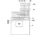
次に、光音響画像を作成する際に、図1に示したプローブ11の受信開口を制御する点について説明する。図2はこの説明をするための概略図であり、ここではプローブ11を、複数の音響波振動子G1〜G16が一次元アレイ状に並設されてなるものとして示している。つまり本例では、プローブ11を16ch(チャンネル)のものとして示している。なお、これらの音響波振動子G1〜G16が、図1に示した振動子アレイ20である。また、図2では音響波振動子G1〜G16のうち、一部のものにだけ附番を与えているが、図中の左側から右側に向かって音響波振動子G1、音響波振動子G2、・・・音響波振動子G16という順序で並んでいるものとする。
Next, the point of controlling the reception aperture of the
また、Fはドップラ画像を生成可能な領域を示し、ROIはその領域Fの中に設定された関心領域を示している。なお、ここでは、プローブ11の位置を上記領域Fに対する相対位置として示しているが、この相対位置は、光音響画像を生成する際のプローブ11と被検体Mとの位置関係と対応している。
F indicates a region where a Doppler image can be generated, and ROI indicates a region of interest set in the region F. Here, the position of the
また21Cは、図1に示した受信回路21の受信チャンネルを概念的に示している。ここでは、受信回路21がC1〜C8の8つの受信チャンネルを有しているものとする。そして19は、受信チャンネル21Cとプローブ11との間に介設されたマルチプレクサ(図1を参照)を示している。
21C conceptually shows the reception channel of the
以上の構成において、16chの音響波振動子G1〜G16から発せられる信号を全て受信回路21で受信する場合は、まず8chの音響波振動子G1〜G8から発せられた信号が、8chの受信チャンネルC1〜C8から受信回路21に受信される。その後、マルチプレクサ19が切り換えられて、残りの8chの音響波振動子G9〜G16から発せられた信号が、8chの受信チャンネルC1〜C8から受信回路21に受信される。
In the above configuration, when all the signals emitted from the 16ch acoustic wave transducers G1 to G16 are received by the receiving
ここで、光音響画像を生成する際にはマルチプレクサ19が図示の通りの状態とされる。そして、被検体Mのある1つの断面の光音響画像を生成するに当たり、この状態下で1回だけレーザ光Lが被検体Mに向けて出射される。こうしてレーザ光Lが1回出射された際、8chの音響波振動子G4〜G11から出力される信号(光音響波検出信号)だけが、8chの受信チャンネルC1〜C8から受信回路21に受信される。その後、マルチプレクサ19の切り換えはなされず、以上で、1つの断面の光音響画像を生成するための光音響波検出信号の受信が完了する。
Here, when the photoacoustic image is generated, the
以上のようにして本例では、16chの音響波振動子G1〜G16のうち一部のチャンネル、すなわち8chの音響波振動子G1〜G3およびG12〜G16から出力される信号(光音響波検出信号)はマルチプレクサ19において遮断され、受信回路21では受信されない。それにより、光音響画像生成のフレームレートを上げて、光音響画像のリアルタイム性を向上させることができる。なお図2では、受信開口となる音響波振動子を、ハッチングを付して示してある(図4〜図7でも同様)。
As described above, in this example, signals (photoacoustic wave detection signals) output from some of the 16-channel acoustic wave transducers G1 to G16, that is, the 8-channel acoustic wave transducers G1 to G3 and G12 to G16. ) Is blocked by the
上記の受信開口とする8chの音響波振動子G4〜G11は、ドップラ画像信号を取得する範囲である関心領域ROIの大きさおよび位置に基づいて定められる。すなわち本例では、関心領域ROIの全域と向かい合って並んでいる音響波振動子を全て受信開口に設定できるように、8chの音響波振動子G4〜G11が受信開口に設定される。 The 8ch acoustic wave transducers G4 to G11 serving as the reception openings are determined based on the size and position of the region of interest ROI, which is a range in which the Doppler image signal is acquired. That is, in this example, the 8ch acoustic wave transducers G4 to G11 are set as reception openings so that all the acoustic wave transducers arranged facing the entire region of interest ROI can be set as reception openings.
ここで、受信開口の設定を、図3に示す実際の超音波画像を用いて説明する。この図において、黒の背景の中にある扇状部分が例えばBモード画像等の超音波画像であり、その中に、ドップラ画像の表示範囲である関心領域ROIが設定される。なおこの図3の例では、Aで示す関心領域ROIの中央部近辺に血流部が示され、Bで示す関心領域の図中左右の端部に近い部分には、表示したい対象物は存在していない。 Here, the setting of the reception aperture will be described using an actual ultrasonic image shown in FIG. In this figure, a fan-shaped portion in a black background is an ultrasonic image such as a B-mode image, and a region of interest ROI that is a display range of a Doppler image is set therein. In the example of FIG. 3, a blood flow portion is shown near the center of the region of interest ROI indicated by A, and there is an object to be displayed in a portion near the left and right ends of the region of interest indicated by B. Not done.
ドップラ画像においては、一般に血流部が表示される。また光音響画像は多くの場合、レーザ光L等の光を良く吸収して光音響波を発する血管部分を表示するために用いられる。したがって、上記血流部が含まれるように関心領域ROIが設定されていることを前提として、少なくともこの関心領域ROIについて光音響波検出信号を生成可能にプローブ11の受信開口を設定しておけば、受信開口が小さく制限されていても、生成される光音響画像は上述のように血管部分を表示できるものとなる。
In the Doppler image, a blood flow part is generally displayed. In many cases, the photoacoustic image is used to display a blood vessel portion that absorbs light such as the laser light L and emits a photoacoustic wave. Accordingly, on the assumption that the region of interest ROI is set so as to include the blood flow part, the reception aperture of the
なおマルチプレクサ19の状態は、関心領域ROIを示す情報に基づいて制御部34によって制御される。つまり本実施形態では、マルチプレクサ19および制御部34が受信開口制御手段を構成している。また、関心領域設定部26および制御部34が、関心領域を設定する手段を構成している。
Note that the state of the
次に図4に、プローブ11の受信開口設定の別の例を示す。この例では、受信開口の大きさは図2の例と同様に8chとされるが、関心領域ROIの位置が図2の例と異なるので、その位置に対応して、音響波振動子G8〜G15が受信開口とされている。
Next, FIG. 4 shows another example of the reception aperture setting of the
以下、上述した効果を、実際の装置に即した例を用いてより詳しく説明する。本例では、プローブ11の音響波振動子が128ch、受信回路21の受信チャンネルが64ch、レーザ光Lの出射の繰り返し周波数が10Hzであるとする。この例では、1枚の光音響画像を生成するために通常、
(1)レーザ光Lの出射(1回目)
(2)64chの音響波振動子により光音響波を検出(1回目)
(3)レーザ光Lの出射(2回目)
(4)残りの64chの音響波振動子により光音響波を検出(2回目)
(5)光音響画像生成部24(図1を参照)により光音響画像を生成
というように、レーザ光Lの出射を2回行う必要がある。すると、レーザ光Lの出射の繰り返し周波数が10Hzであることから、光音響画像生成の繰り返し周波数は5Hz(フレームレートは5枚/秒)となってしまう。Hereinafter, the above-described effect will be described in more detail using an example according to an actual apparatus. In this example, it is assumed that the acoustic wave vibrator of the
(1) Emitting laser beam L (first time)
(2) Detect photoacoustic wave by 64ch acoustic wave vibrator (first time)
(3) Emitting laser beam L (second time)
(4) Photoacoustic wave is detected by the remaining 64ch acoustic wave transducer (second time)
(5) It is necessary to emit the laser beam L twice, such as generating a photoacoustic image by the photoacoustic image generation unit 24 (see FIG. 1). Then, since the repetition frequency of emission of the laser light L is 10 Hz, the repetition frequency of photoacoustic image generation is 5 Hz (frame rate is 5 frames / second).
それに対して、基本的に図2の例と同じようにして、プローブ11の音響波振動子が本来128chであるところ、半分の64chを受信開口とする場合は、1枚の光音響画像を生成するために、
(1)レーザ光Lの出射(1回目)
(2)64chの音響波振動子により光音響波を検出(1回目)
(3)光音響画像生成部24(図1を参照)により光音響画像を生成
というように、レーザ光Lの出射を1回だけ行えばよいことになる。これにより、光音響画像生成の繰り返し周波数を、レーザ光Lの出射の繰り返し周波数と同じ10Hz(フレームレートは10枚/秒)とすることができる。On the other hand, in the same manner as in the example of FIG. 2, when the acoustic wave transducer of the
(1) Emitting laser beam L (first time)
(2) Detect photoacoustic wave by 64ch acoustic wave vibrator (first time)
(3) The laser light L needs to be emitted only once, such as generation of a photoacoustic image by the photoacoustic image generation unit 24 (see FIG. 1). Thereby, the repetition frequency of photoacoustic image generation can be set to 10 Hz (the frame rate is 10 frames / second) which is the same as the repetition frequency of emission of the laser light L.
一般的に、関心領域ROIは、プローブ11によって超音波画像を取得できる範囲の中の一部領域に設定されることが多い。したがって、プローブ11の受信開口を、本来プローブ11が備えている受信開口の1/2程度まで制限しても、血管部分等の所望部分を表示できる光音響画像を生成可能であることが多い。そこで本発明によれば、多くの場合、上に述べた通り光音響画像生成において、本来プローブ11が備えている受信開口を全て使用する場合と比べて、フレームレートを向上させることができる。
In general, the region of interest ROI is often set to a partial region within a range in which an ultrasound image can be acquired by the
また一般に、光音響画像は画像化可能領域が浅い。つまり、被検体の光照射側の表面から比較的近い所に有る部分しか画像化できない。そのため、ドップラ画像の関心領域ROIから離れた部分と向き合う音響波振動子が出力する光音響波検出信号は、音響波振動子の受信指向角が深いことから画質の向上に寄与せず、むしろノイズを増やすことで光音響画像の画質を劣化させることも多い。それに対して、図2に示す例あるいは図4に示す例では、主に受信指向角が浅い音響波振動子が出力する信号に基づいて光音響画像を生成することになるので、光音響画像の画質向上も期待できる。 In general, the photoacoustic image has a shallow imageable area. That is, only a portion that is relatively close to the surface on the light irradiation side of the subject can be imaged. For this reason, the photoacoustic wave detection signal output by the acoustic wave transducer facing the portion of the Doppler image away from the region of interest ROI does not contribute to the improvement of image quality because the reception directivity angle of the acoustic wave transducer is deep. In many cases, the image quality of the photoacoustic image is deteriorated by increasing. On the other hand, in the example shown in FIG. 2 or the example shown in FIG. 4, a photoacoustic image is generated mainly based on a signal output from an acoustic wave transducer having a shallow reception directivity angle. Expected to improve image quality.
なお、関心領域ROIが比較的小さく、設定されたプローブ11の受信開口に対応する音響波振動子のチャンネル数が64chより小さい場合は、受信開口を、フレームレートが低下しない範囲内で広げてもよい。例えば、ドップラ画像の関心領域ROIに基づいて定められたプローブ11の受信開口に対応する音響波振動子のチャンネル数が32chの場合、受信開口を64chまで広げてもよい。
When the region of interest ROI is relatively small and the number of channels of the acoustic wave transducer corresponding to the set reception aperture of the
次に図5を参照して、プローブ11の受信開口設定の別の例を示す。図2に示した例および図4に示した例では、関心領域ROIの全域と向かい合って並んでいる音響波振動子を全て受信開口に設定している。しかし、関心領域ROIが比較的大きい(音響波振動子の並び方向に長い)場合は、上記2つの例のように受信開口を設定すると、それらの受信開口の数が、受信回路21の受信チャンネルC1〜C8の数よりも大きくなることがある。そうなった場合は、光音響画像生成のフレームレートが低下することになる。
Next, with reference to FIG. 5, another example of the reception aperture setting of the
そのようなことを防ぐために図5の例では、関心領域ROIの全域と向かい合って並んでいる音響波振動子のうち、一部の音響波振動子のみを受信開口に設定するようにしている。つまり本例では具体的に、関心領域ROIの全域と向かい合って並んでいる14個の音響波振動子のうち、8個の音響波振動子G2、G4、G6、G8、G9、G11、G13およびG15のみを受信開口としている。こうすることにより、プローブ11の受信開口の数を受信回路21の受信チャンネルC1〜C8の数と一致させ、光音響画像生成のフレームレートが低下することを防止できる。この効果は、後述する図6の例でも同様に得られる。
In order to prevent such a situation, in the example of FIG. 5, only some acoustic wave transducers are set as reception openings among the acoustic transducers arranged facing the entire region of interest ROI. That is, in this example, specifically, among the 14 acoustic wave vibrators that are arranged facing the entire region of interest ROI, eight acoustic wave vibrators G2, G4, G6, G8, G9, G11, G13 and Only G15 is a reception aperture. By doing so, the number of reception apertures of the
以上のようなプローブ11の受信開口の設定は、先に述べた実際の装置に即した例、つまりプローブ11の音響波振動子が128ch、受信回路21の受信チャンネルが64ch、レーザ光Lの出射の繰り返し周波数が10Hzである例においても適用可能である。そうした場合は、光音響画像生成の繰り返し周波数を、レーザ光Lの出射の繰り返し周波数と同じ10Hzとすることができる。
The setting of the reception aperture of the
図6に、プローブ11の受信開口設定のさらに別の例を示す。この図6に示す例は、図5に示した例と基本的に同じで、受信開口とする音響波振動子の並び方が一部異なるだけのものである。
FIG. 6 shows still another example of the reception aperture setting of the
上述した図5の例および図6の例では、関心領域ROIの全域と向かい合って並んでいる複数の音響波振動子のうち、受信開口に設定されない音響波振動子から出力された信号(光音響波検出信号)を、受信開口に設定された音響波振動子から出力された信号を補間して求めるのが望ましい。その補間して求めた信号に基づいて光音響画像を生成すれば、輝度や濃度の分布等において違和感の無い光音響画像を生成可能となる。 In the example of FIG. 5 and the example of FIG. 6 described above, a signal (photoacoustic signal) output from an acoustic wave transducer that is not set in the reception aperture among a plurality of acoustic transducers arranged opposite to the entire region of interest ROI. It is desirable to obtain the wave detection signal) by interpolating the signal output from the acoustic wave vibrator set in the reception aperture. If a photoacoustic image is generated based on the signal obtained by the interpolation, a photoacoustic image having no sense of incongruity in luminance and density distribution can be generated.
上記の補間は、光音響画像を再構成した後の信号に対して行ってもよいし、再構成の前の信号に対して行ってもよい。例えば前者のようにする場合は、図1に示した光音響画像生成部24に補間機能を持たせて、この光音響画像生成部24を補間手段として用いてもよい。 Said interpolation may be performed with respect to the signal after reconstructing a photoacoustic image, and may be performed with respect to the signal before reconstruction. For example, in the case of the former, the photoacoustic image generation unit 24 shown in FIG. 1 may be provided with an interpolation function, and the photoacoustic image generation unit 24 may be used as an interpolation unit.
図7に、プローブ11の受信開口設定のさらに別の例を示す。この図7に示す例は、上述した図5の例および図6の例と同様に、関心領域ROIの全域と向かい合って並んでいる音響波振動子のうち、一部の音響波振動子G2、G4、G6、G7、G8、G9、G11およびG13のみを受信開口に設定するものである。それにより、図5の例および図6の例におけるのと同様の効果が得られる。
FIG. 7 shows still another example of the reception aperture setting of the
それに加えて図7の例では、受信開口とする音響波振動子として、音響波振動子G2、G4、G6、G7、G8、G9、G11およびG13を選択することにより、受信開口となる音響波振動子が、関心領域ROIの端部に向かい合う位置と比べて、関心領域ROIの中央部に向かい合う位置においてより密に存在する状態に設定している。 In addition, in the example of FIG. 7, the acoustic wave that becomes the reception aperture is selected by selecting the acoustic wave transducers G2, G4, G6, G7, G8, G9, G11, and G13 as the acoustic wave transducer that is the reception aperture. The vibrators are set to be in a more dense state at a position facing the center of the region of interest ROI than at a position facing the end of the region of interest ROI.
ここで、一般に関心領域ROIは、血流部等が中央部近くに有るように設定されることが多い。そうした場合、光音響波検出信号は、関心領域ROIの周辺部ほど信号強度が低く、そのため、再構成後の光音響画像におけるノイズ発生の原因となることもある。そこで、本例のようにプローブ11の受信開口を設定して、関心領域ROIの端部近くから発生する光音響波を検出した信号は光音響画像生成のために余り利用しないようにすれば、光音響画像の画質向上の効果が得られる。
Here, in general, the region of interest ROI is often set so that the blood flow portion and the like are near the center. In such a case, the signal intensity of the photoacoustic wave detection signal is lower in the peripheral part of the region of interest ROI, and therefore may cause noise in the reconstructed photoacoustic image. Therefore, if the reception aperture of the
以上、プローブ11のチャンネル数(音響波振動子の数)が128chで、受信回路21側の受信チャンネル数が64chの場合を例に挙げて詳しく説明したが、本発明ではそれらのチャンネル数は例示したものに限定されない。例えば、プローブ11のチャンネル数は196ch、256ch、あるいは512ch等であってもよく、受信回路21側の受信チャンネル数は128ch、あるいは256ch等であってもよい。
As described above, the case where the number of channels of the probe 11 (the number of acoustic wave transducers) is 128 ch and the number of reception channels on the receiving
また、マルチプレクサ19(図1を参照)は、3以上の入力系を備えるものであっても構わない。さらに、プローブ11の受信開口を設定する手段としては、このマルチプレクサ19以外の手段が用いられても構わない。
The multiplexer 19 (see FIG. 1) may include three or more input systems. Further, means other than the
10 音響波画像生成装置
11 プローブ
12 超音波ユニット
13 レーザユニット
14 画像表示部
14a 表示画面
15 入力部
20 振動子アレイ
21 受信回路
21C 受信回路の受信チャンネル
22 受信メモリ
23 データ分離手段
24 光音響画像生成部
25 ドップラ画像生成部
26 関心領域設定部
27 画像表示制御部
33 送信制御回路
34 制御部
40 光出射部
50 筺体
60 光ファイバ
65 吸収体
F ドップラ画像を生成可能な領域
G1、G2、・・・G16 音響波振動子
Idp ドップラ画像
Ipa 光音響画像
L レーザ光(測定光)
M 被検体
U 音響波DESCRIPTION OF
M Subject U Acoustic wave
Claims (12)
前記ドップラ画像にて関心領域を設定する手段と、
前記音響波検出プローブの前記光音響波を検出する受信開口を、前記設定された関心領域の大きさに基づいて、該音響波検出プローブが有する全部の受信開口よりも小さい開口に設定し、かつ、前記音響波検出プローブの前記光音響波を検出する受信開口の位置を、前記設定された関心領域の位置に基づいて設定する受信開口制御手段と、
を有する音響波画像生成装置。A photoacoustic image is generated based on a signal obtained by detecting a photoacoustic wave generated from within the subject by an acoustic wave detection probe by receiving light emitted toward the subject, and the subject In an acoustic wave image generation device that generates a Doppler image related to a specimen,
Means for setting a region of interest in the Doppler image;
Based on the set size of the region of interest, the reception aperture for detecting the photoacoustic wave of the acoustic wave detection probe is set to an aperture smaller than all the reception apertures of the acoustic wave detection probe, and Receiving aperture control means for setting the position of the receiving aperture for detecting the photoacoustic wave of the acoustic wave detection probe based on the position of the set region of interest;
An acoustic wave image generation device having
前記受信開口制御手段は、受信開口とする音響波振動子以外の音響波振動子のうち少なくとも一部の音響波振動子から出力される光音響波検出信号を遮断する手段である請求項1記載の音響波画像生成装置。As the acoustic wave detection probe, an acoustic wave detection probe in which a plurality of acoustic wave transducers capable of detecting the photoacoustic wave are arranged in parallel is used,
2. The reception aperture control means is means for blocking a photoacoustic wave detection signal output from at least some of the acoustic wave transducers other than the acoustic wave transducer serving as a reception aperture. Acoustic wave image generation apparatus.
前記ドップラ画像にて関心領域を設定し、
前記音響波検出プローブの前記光音響波を検出する受信開口を、前記設定された関心領域の大きさに基づいて、該音響波検出プローブが有する全部の受信開口よりも小さい開口に設定し、かつ、前記音響波検出プローブの前記光音響波を検出する受信開口の位置を、前記設定された関心領域の位置に基づいて設定する音響波画像生成方法。A photoacoustic image is generated based on a signal obtained by detecting a photoacoustic wave generated from within the subject by an acoustic wave detection probe by receiving light emitted toward the subject, and the subject In an acoustic wave image generation method for generating a Doppler image related to a specimen,
Set the region of interest in the Doppler image,
Based on the set size of the region of interest, the reception aperture for detecting the photoacoustic wave of the acoustic wave detection probe is set to an aperture smaller than all the reception apertures of the acoustic wave detection probe, and The acoustic wave image generation method of setting the position of the reception aperture for detecting the photoacoustic wave of the acoustic wave detection probe based on the set position of the region of interest.
受信開口とする音響波振動子以外の音響波振動子のうち少なくとも一部の音響波振動子から出力される光音響波検出信号を遮断することにより、前記受信開口の設定を行う請求項7記載の音響波画像生成方法。As the acoustic wave detection probe, an acoustic wave detection probe in which a plurality of acoustic wave transducers capable of detecting the photoacoustic wave are arranged in parallel is used.
8. The reception aperture is set by blocking photoacoustic wave detection signals output from at least some of the acoustic wave transducers other than the acoustic wave transducer serving as a reception aperture. Acoustic wave image generation method.
Applications Claiming Priority (3)
| Application Number | Priority Date | Filing Date | Title |
|---|---|---|---|
| JP2016022210 | 2016-02-08 | ||
| JP2016022210 | 2016-02-08 | ||
| PCT/JP2017/004072 WO2017138459A1 (en) | 2016-02-08 | 2017-02-03 | Acoustic wave image generation device and acoustic wave image generation method |
Publications (2)
| Publication Number | Publication Date |
|---|---|
| JPWO2017138459A1 JPWO2017138459A1 (en) | 2018-07-05 |
| JP6475369B2 true JP6475369B2 (en) | 2019-02-27 |
Family
ID=59563067
Family Applications (1)
| Application Number | Title | Priority Date | Filing Date |
|---|---|---|---|
| JP2017566920A Active JP6475369B2 (en) | 2016-02-08 | 2017-02-03 | Acoustic wave image generation apparatus and acoustic wave image generation method |
Country Status (5)
| Country | Link |
|---|---|
| US (1) | US11119199B2 (en) |
| EP (1) | EP3415097B1 (en) |
| JP (1) | JP6475369B2 (en) |
| CN (1) | CN108601583B (en) |
| WO (1) | WO2017138459A1 (en) |
Families Citing this family (3)
| Publication number | Priority date | Publication date | Assignee | Title |
|---|---|---|---|---|
| CN113167767A (en) * | 2018-11-27 | 2021-07-23 | 株式会社岛津制作所 | Defect inspection apparatus and defect inspection method |
| JP2022068431A (en) * | 2020-10-22 | 2022-05-10 | 富士フイルムヘルスケア株式会社 | Ultrasonic probe |
| CN113367660B (en) * | 2021-06-09 | 2022-11-25 | 东北大学秦皇岛分校 | Photoacoustic Doppler flow velocity measuring device and method |
Family Cites Families (35)
| Publication number | Priority date | Publication date | Assignee | Title |
|---|---|---|---|---|
| US4463608A (en) * | 1979-05-07 | 1984-08-07 | Yokogawa Hokushin Electric Corp. | Ultrasound imaging system |
| US6080107A (en) * | 1999-01-26 | 2000-06-27 | Hewlett-Packard Company | Methods for the use of contrast agents in ultrasonic imaging |
| JP4426478B2 (en) * | 2005-02-18 | 2010-03-03 | アロカ株式会社 | Ultrasonic diagnostic equipment |
| WO2007100937A2 (en) * | 2006-01-19 | 2007-09-07 | The Regents Of The University Of Michigan | System and method for spectroscopic photoacoustic tomography |
| EP2034878A2 (en) | 2006-06-23 | 2009-03-18 | Koninklijke Philips Electronics N.V. | Timing controller for combined photoacoustic and ultrasound imager |
| ATE526882T1 (en) | 2006-12-19 | 2011-10-15 | Koninkl Philips Electronics Nv | COMBINED PHOTOACOUSTIC AND ULTRASONIC DISPLAY SYSTEM |
| US20140142404A1 (en) * | 2008-10-23 | 2014-05-22 | The Washington University | Single-cell label-free photoacoustic flowoxigraphy in vivo |
| WO2010048258A1 (en) * | 2008-10-23 | 2010-04-29 | Washington University In St. Louis | Reflection-mode photoacoustic tomography using a flexibly-supported cantilever beam |
| EP2203733B1 (en) * | 2007-10-25 | 2017-05-03 | Washington University in St. Louis | Confocal photoacoustic microscopy with optical lateral resolution |
| US9451884B2 (en) * | 2007-12-13 | 2016-09-27 | Board Of Trustees Of The University Of Arkansas | Device and method for in vivo detection of clots within circulatory vessels |
| US8353833B2 (en) * | 2008-07-18 | 2013-01-15 | University Of Rochester | Low-cost device for C-scan photoacoustic imaging |
| JP5483905B2 (en) * | 2009-03-03 | 2014-05-07 | キヤノン株式会社 | Ultrasonic device |
| JP5993741B2 (en) * | 2009-10-16 | 2016-09-14 | コーニンクレッカ フィリップス エヌ ヴェKoninklijke Philips N.V. | Active ultrasound imaging based on photoacoustic contrast agents |
| WO2011091423A2 (en) * | 2010-01-25 | 2011-07-28 | The Arizona Board Of Regents On Behalf Of The University Of Arizona | Ultrasonic/photoacoustic imaging devices and methods |
| CN102946809A (en) * | 2010-02-01 | 2013-02-27 | 松下电器产业株式会社 | Ultrasonic probe and ultrasonic examination device using same |
| US9999354B2 (en) * | 2011-01-21 | 2018-06-19 | National Research Council Of Canada | Biological tissue inspection method and system |
| JP5655021B2 (en) * | 2011-03-29 | 2015-01-14 | 富士フイルム株式会社 | Photoacoustic imaging method and apparatus |
| JP2012223367A (en) * | 2011-04-20 | 2012-11-15 | Fujifilm Corp | Photoacoustic image generation apparatus and method |
| JP5681141B2 (en) * | 2011-05-13 | 2015-03-04 | 富士フイルム株式会社 | Tomographic image generating apparatus, method, and program |
| JP5713968B2 (en) * | 2011-07-29 | 2015-05-07 | 富士フイルム株式会社 | Photoacoustic image generating apparatus and acoustic wave unit |
| JP6132466B2 (en) | 2012-02-07 | 2017-05-24 | キヤノン株式会社 | Subject information acquisition apparatus and subject information acquisition method |
| WO2014070993A1 (en) * | 2012-10-31 | 2014-05-08 | Cerebrosonics, Llc | Novel system for emboli detection in the brain using a transcranial doppler photoacoustic device capable of vasculature and perfusion measurement |
| EP2740410B1 (en) | 2012-12-04 | 2018-05-16 | Canon Kabushiki Kaisha | Subject information acquisition device, method for controlling subject information acquisition device, and program therefor |
| KR20140084828A (en) * | 2012-12-27 | 2014-07-07 | 삼성전자주식회사 | Photoacoustic probe and photoacoustic apparatus having the same |
| US20140194740A1 (en) * | 2013-01-07 | 2014-07-10 | Cerebrosonics, Llc | Emboli detection in the brain using a transcranial doppler photoacoustic device capable of vasculature and perfusion measurement |
| EP2754388B1 (en) * | 2013-01-15 | 2020-09-09 | Helmholtz Zentrum München Deutsches Forschungszentrum für Gesundheit und Umwelt GmbH | System and method for quality-enhanced high-rate optoacoustic imaging of an object |
| JP5936559B2 (en) | 2013-01-18 | 2016-06-22 | 富士フイルム株式会社 | Photoacoustic image generation apparatus and photoacoustic image generation method |
| JP6177530B2 (en) * | 2013-01-18 | 2017-08-09 | 富士フイルム株式会社 | Doppler measuring device and doppler measuring method |
| US20140276059A1 (en) * | 2013-03-12 | 2014-09-18 | Volcano Corporation | Externally imaging a body structure within a patient |
| KR101533591B1 (en) * | 2013-07-08 | 2015-07-06 | 삼성메디슨 주식회사 | Medical imaging apparatus and method of providing medical images |
| EP3071094A1 (en) * | 2013-11-22 | 2016-09-28 | Massachusetts Institute Of Technology | System and method for non-contact ultrasound |
| JP2015150238A (en) * | 2014-02-14 | 2015-08-24 | オリンパス株式会社 | Ultrasonic observation device, operation method of the same and operation program of the same |
| KR102268668B1 (en) * | 2014-03-12 | 2021-06-24 | 삼성메디슨 주식회사 | The method and apparatus for displaying a plurality of different images of an object |
| JP6327900B2 (en) | 2014-03-24 | 2018-05-23 | キヤノン株式会社 | Subject information acquisition apparatus, breast examination apparatus and apparatus |
| WO2016036173A1 (en) * | 2014-09-04 | 2016-03-10 | Samsung Electronics Co., Ltd. | Ultrasound probe and operating method thereof |
-
2017
- 2017-02-03 EP EP17750182.2A patent/EP3415097B1/en active Active
- 2017-02-03 JP JP2017566920A patent/JP6475369B2/en active Active
- 2017-02-03 CN CN201780010312.2A patent/CN108601583B/en active Active
- 2017-02-03 WO PCT/JP2017/004072 patent/WO2017138459A1/en active Application Filing
-
2018
- 2018-08-03 US US16/054,466 patent/US11119199B2/en active Active
Also Published As
| Publication number | Publication date |
|---|---|
| CN108601583A (en) | 2018-09-28 |
| EP3415097B1 (en) | 2020-07-15 |
| JPWO2017138459A1 (en) | 2018-07-05 |
| WO2017138459A1 (en) | 2017-08-17 |
| EP3415097A1 (en) | 2018-12-19 |
| CN108601583B (en) | 2021-05-11 |
| US20180341011A1 (en) | 2018-11-29 |
| US11119199B2 (en) | 2021-09-14 |
| EP3415097A4 (en) | 2019-01-23 |
Similar Documents
| Publication | Publication Date | Title |
|---|---|---|
| US9974440B2 (en) | Photoacoustic image generation device and method | |
| JP5661451B2 (en) | Subject information acquisition apparatus and subject information acquisition method | |
| US11083376B2 (en) | Photoacoustic measurement device and signal processing method of photoacoustic measurement device | |
| WO2012140865A1 (en) | Object information acquiring apparatus and object information acquiring method | |
| US9995717B2 (en) | Object information acquiring apparatus and object information acquiring method | |
| JP5777358B2 (en) | Subject information acquisition apparatus and signal processing method | |
| JP6132466B2 (en) | Subject information acquisition apparatus and subject information acquisition method | |
| JP6049215B2 (en) | Photoacoustic measurement apparatus, signal processing apparatus and signal processing method used therefor | |
| US20140360271A1 (en) | Object information acquiring apparatus and method of controlling object information acquiring apparatus | |
| US11119199B2 (en) | Acoustic wave image generation apparatus and acoustic wave image generation method | |
| JP2014131596A (en) | Subject information acquisition device, control method of subject information acquisition device, program | |
| JP2018061725A (en) | Subject information acquisition device and signal processing method | |
| US11399719B2 (en) | Probe for photoacoustic measurement and photoacoustic measurement apparatus including same | |
| JP6091235B2 (en) | Subject information acquisition device | |
| WO2019044594A1 (en) | Photoacoustic image generation device and image acquisition method | |
| WO2019044593A1 (en) | Photoacoustic image generation apparatus and photoacoustic image generation method | |
| JP2019088346A (en) | Photoacoustic apparatus and subject information acquisition method | |
| JP6643108B2 (en) | Subject information acquisition device and subject information acquisition method | |
| JP6513121B2 (en) | Processing apparatus, object information acquiring apparatus, display method of photoacoustic image, and program | |
| JP6381043B2 (en) | Photoacoustic measurement probe, probe unit including the same, and photoacoustic measurement apparatus | |
| JP2019136520A (en) | Processing device, photoacoustic image display method, and program | |
| JP2014023680A (en) | Subject information acquiring device, and control method and presentation method for the same | |
| JP2020018466A (en) | Information processing device, information processing method, and program | |
| JP2019155004A (en) | Photoacoustic apparatus and subject information acquisition method |
Legal Events
| Date | Code | Title | Description |
|---|---|---|---|
| A621 | Written request for application examination |
Free format text: JAPANESE INTERMEDIATE CODE: A621 Effective date: 20180314 |
|
| TRDD | Decision of grant or rejection written | ||
| A01 | Written decision to grant a patent or to grant a registration (utility model) |
Free format text: JAPANESE INTERMEDIATE CODE: A01 Effective date: 20190108 |
|
| A61 | First payment of annual fees (during grant procedure) |
Free format text: JAPANESE INTERMEDIATE CODE: A61 Effective date: 20190131 |
|
| R150 | Certificate of patent or registration of utility model |
Ref document number: 6475369 Country of ref document: JP Free format text: JAPANESE INTERMEDIATE CODE: R150 |
|
| R250 | Receipt of annual fees |
Free format text: JAPANESE INTERMEDIATE CODE: R250 |
|
| R250 | Receipt of annual fees |
Free format text: JAPANESE INTERMEDIATE CODE: R250 |
|
| R250 | Receipt of annual fees |
Free format text: JAPANESE INTERMEDIATE CODE: R250 |