EP2307934B1 - Universal interface for a wireless adapter - Google Patents
Universal interface for a wireless adapter Download PDFInfo
- Publication number
- EP2307934B1 EP2307934B1 EP09781421.4A EP09781421A EP2307934B1 EP 2307934 B1 EP2307934 B1 EP 2307934B1 EP 09781421 A EP09781421 A EP 09781421A EP 2307934 B1 EP2307934 B1 EP 2307934B1
- Authority
- EP
- European Patent Office
- Prior art keywords
- terminal
- wireless adapter
- interface
- eeext
- supply unit
- Prior art date
- Legal status (The legal status is an assumption and is not a legal conclusion. Google has not performed a legal analysis and makes no representation as to the accuracy of the status listed.)
- Active
Links
- 238000004891 communication Methods 0.000 claims description 48
- 238000009434 installation Methods 0.000 claims description 27
- 238000004880 explosion Methods 0.000 claims description 5
- 231100001261 hazardous Toxicity 0.000 claims description 2
- 238000000034 method Methods 0.000 description 8
- 230000005540 biological transmission Effects 0.000 description 7
- 238000005516 engineering process Methods 0.000 description 6
- 239000002360 explosive Substances 0.000 description 2
- 239000000446 fuel Substances 0.000 description 2
- 238000004801 process automation Methods 0.000 description 2
- 230000008878 coupling Effects 0.000 description 1
- 238000010168 coupling process Methods 0.000 description 1
- 238000005859 coupling reaction Methods 0.000 description 1
- 238000011161 development Methods 0.000 description 1
- 230000000694 effects Effects 0.000 description 1
- 239000007788 liquid Substances 0.000 description 1
- 238000005259 measurement Methods 0.000 description 1
- 238000012544 monitoring process Methods 0.000 description 1
- 238000004886 process control Methods 0.000 description 1
- 238000012800 visualization Methods 0.000 description 1
Images


Classifications
-
- G—PHYSICS
- G05—CONTROLLING; REGULATING
- G05B—CONTROL OR REGULATING SYSTEMS IN GENERAL; FUNCTIONAL ELEMENTS OF SUCH SYSTEMS; MONITORING OR TESTING ARRANGEMENTS FOR SUCH SYSTEMS OR ELEMENTS
- G05B19/00—Programme-control systems
- G05B19/02—Programme-control systems electric
- G05B19/04—Programme control other than numerical control, i.e. in sequence controllers or logic controllers
- G05B19/042—Programme control other than numerical control, i.e. in sequence controllers or logic controllers using digital processors
- G05B19/0423—Input/output
-
- G—PHYSICS
- G05—CONTROLLING; REGULATING
- G05B—CONTROL OR REGULATING SYSTEMS IN GENERAL; FUNCTIONAL ELEMENTS OF SUCH SYSTEMS; MONITORING OR TESTING ARRANGEMENTS FOR SUCH SYSTEMS OR ELEMENTS
- G05B2219/00—Program-control systems
- G05B2219/20—Pc systems
- G05B2219/21—Pc I-O input output
- G05B2219/21116—Universal cabling; control interface between processor and devices
-
- G—PHYSICS
- G05—CONTROLLING; REGULATING
- G05B—CONTROL OR REGULATING SYSTEMS IN GENERAL; FUNCTIONAL ELEMENTS OF SUCH SYSTEMS; MONITORING OR TESTING ARRANGEMENTS FOR SUCH SYSTEMS OR ELEMENTS
- G05B2219/00—Program-control systems
- G05B2219/20—Pc systems
- G05B2219/25—Pc structure of the system
- G05B2219/25451—Connect module to bus using interface with adaptive logic
Definitions
- the invention relates to a universal interface for a wireless adapter, which supports a communication protocol used in automation technology, wherein the wireless adapter is assigned a first power supply unit for supplying power to the wireless adapter and a radio module for communicating with a higher-level control unit via a radio network.
- field devices are often used to detect and / or influence process variables.
- Sensors such as fill level measuring devices, flowmeters, pressure and temperature measuring devices, pH redox potential measuring devices, conductivity measuring devices, etc., which record the corresponding process variables level, flow, pressure, temperature, pH or conductivity, are used to record process variables.
- actuators such as valves or pumps, through which the flow of a liquid in a pipe section or the level can be changed in a container.
- field devices are all devices that are used close to the process and that provide or process process-relevant information.
- the higher-level units serve, among other things, for process control, process visualization, process monitoring and commissioning of the field devices.
- the measured values acquired by the field devices are transmitted via the connected bus system to one or possibly also to a plurality of higher-level unit (s).
- higher-level unit data transmission from the higher-level unit via the bus system to the field devices is required; this is used in particular for configuring and parameterizing field devices or for diagnostic purposes.
- the field device is operated via the bus system from the higher-level unit.
- radio network for sensors are further specified in the IEEE 802.15.4 standard.
- newer field devices in particular sensors and actuators, are partly designed as radio field devices.
- the radio unit and the power source may be provided in the field device itself or in a radio module permanently connected to the field device. The power source enables a self-sufficient power supply of the field device.
- a corresponding wireless adapter is for example in the document WO 2005/103851 A1 described.
- the wireless adapter is usually connected to a Fieldbus communication interface of the field device releasably connected. Via the fieldbus communication interface, the field device can send the data to be transmitted via the bus system to the wireless adapter, which then transmits them via radio to the destination. Conversely, the wireless adapter can receive data via radio and forward it to the field device via the fieldbus communication interface.
- the field device can be supplied with electrical power via a power supply unit of the wireless adapter.
- the communication for example, with a higher-level unit, usually handled by the wireless interface of the radio field device or the wireless adapter.
- radio field devices or wireless adapters usually have a wired communication interface.
- a wired communication interface for example, a configuration of the wireless field device or the wireless adapter via a service and / or operating unit, such as a handheld communicator, which is connected to the wired communication interface, for example, possible.
- the wired communication interface can be designed as a fieldbus communication interface, so that the communication about it is handled according to a bus system, such as according to one of the standard bus systems Profibus®, Foundation® Fieldbus or HART®.
- a fieldbus communication interface the radio field device or the wireless adapter can also be connected to a corresponding wired fieldbus.
- the power supply unit or the power source of a wireless adapter or a radio field device for example, one in the wireless adapter or the radio field device provided battery, a fuel cell, a solar power supply and / or a battery.
- the installed base contains the most diverse types of field installations: a large number of field devices are designed as 4-20mA field devices.
- the analog 4-20mA current value represents the measured value.
- the current signal may be overlaid with a digital communication, which is usually - but not limited - based on the HART protocol.
- four-wire field devices can also be subsumed under the term "field installation" in addition to the two-wire field devices;
- HMI devices which are used, for example, to parameterize the wireless adapter, or also the use of the wireless adapter in modem operation.
- a wireless adapter which is designed at least for a commonly used in automation technology protocol for digital communication, is usually tailored to the specific field installation.
- the known solution lacks the necessary flexibility to use the wireless adapter in different field installations. It is obvious that the conventional solutions are therefore very complex to implement.
- the invention has for its object to provide a universal interface for a wireless adapter that allows flexible connection options of different field installations to a wireless adapter.
- the object is achieved in that at least five terminals are provided on the interface, which are designed so that depending on the respective field installation to be connected in each case a subset of the terminals is connectable either with different configurations of field devices or with an operator panel.
- the term 'field installation' is understood to mean the differently designed types of field devices, ie two-wire or four-wire field devices;
- operating devices which are used, for example, for parameterizing the wireless adapter are also included.
- Another important application is the use of the wireless adapter in modem mode.
- the first terminal is a power supply terminal to which the power supply unit is connected.
- the second connection terminal is a first communication terminal which supports the digital communication according to the communication protocol and / or the determination of the analog current signal.
- the communication protocol preferably supports the HART standard, since HART field devices are most widely used in automation technology. It goes without saying that other common in automation technology communication protocols can be supported. Possibly. then provide additional terminals. Examples include the HART protocol, the Profibus protocol or the Foundation Fieldbus protocol.
- the 4-20 mA signal is preferably used, since this standard has prevailed in process automation technology.
- a two-wire field device fed by the energy supply unit of the wireless adapter in which the power supply and the provision of the measured value take place via the same two-wire line, is connected to the first connection terminal and to the second connection terminal.
- the power supply of the field device takes place in this case via the integrated power supply unit in the interface.
- the energy supply unit is, for example, a battery, a solar panel, a rechargeable battery or a fuel cell.
- An advantageous embodiment of the interface according to the invention provides for a third terminal, which, depending on the field installation to be connected, is either a ground terminal for an external power supply unit or a bridge which establishes the connection to the fifth terminal, which will be described in more detail below.
- a four-wire field device which is supplied with energy via a first two-wire line and an external power supply unit, is connected to the wireless adapter via the second connection terminal and the third connection terminal.
- the digital communication signal and / or the current signal representing the measured value are transmitted via the second two-wire line clamped to the second connection terminal and to the third connection terminal of the wireless adapter.
- a fourth connection terminal is a second communication terminal which supports digital communication in accordance with the respective communication protocol of the field installation.
- the fourth terminal is made in duplicate or if the two terminals work functionally the same, since they are connected to each other via a bridge.
- the two-wire field device is connected to the second terminal and to the fourth terminal and that external power supply unit is connected to the third terminal and the fourth terminal.
- a fifth terminal depending on the connected field installation is either a high-impedance ground terminal or a bridge to the third terminal.
- the wireless adapter is used in a two-wire field device for modem operation, the fourth connection terminal and the fifth connection terminal via the two communication lines on the two-wire line, the two-wire Field device connects to the external power supply unit and via which the digital communication takes place.
- the wireless adapter works in modem mode with a field device powered by the external power supply unit provided that the external power supply unit is connected to the third terminal and the fourth terminal, wherein the third terminal and the fifth terminal are connected via a bridge, and wherein the field device via the fourth terminal and the fifth terminal is connected to the wireless adapter ,
- the wireless adapter can also be connected to an HMI device via the interface for parameterization or diagnostics.
- the HMI device is connected to the fourth connection terminal and the fifth connection terminal.
- each of the terminals is assigned either a voltage limit and / or current limiting, which are designed so that when connecting the respective field installation to the wireless adapter for Available power is such that the use of the wireless adapter in connection with the field installation in potentially explosive areas is possible.
- the explosion protection is guaranteed in all applications.
- the circuit components of the interface S of the wireless adapter or the wireless adapter are identical.
- the assignment of the terminals A, B, C, Da, Db, E is changed.
- the interface S according to the invention is designed such that the individual terminals A, B, C, Da, Db, E can be used in different combinations.
- precautions have been taken in the embodiments shown which, depending on the field installation, limit the current or the voltage to permissible limit values.
- the wireless adapter which is not explicitly shown in the figures, moreover has a radio module FM, which enables wireless communication with a higher-level control unit ST via the radio network FN.
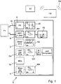
- Fig. 1 shows the assignment of the terminals A, B, C, Da, Db, E of the wireless adapter according to the invention in the case of the connection of a field device F1, which is supplied by the wireless adapter with energy through the power supply unit EE.
- the power supply unit EE also powers the wireless adapter.
- the field device F1 is thus a two-wire field device.
- Two-wire field devices are characterized in that the power supply and the transmission of the measured value, e.g. of a 4-20mA reading and / or digital communication over the same two-wire line VL.
- the first terminal A which serves as a positive pole, is the power supply terminal to which the power supply unit EE of the Wireiess adapter is connected.
- the second connection terminal B is a first communication terminal which either supports the digital communication according to the respective communication protocol, eg the HART protocol, and / or the determination of the analog current signal, in particular a 4-20 mA current signal.
- a voltage limitation UB is connected in parallel with the energy supply unit EE.
- a DC voltage is provided, which can reach a maximum of the Z voltage of the diode D (reverse direction).
- the operating voltage of the diode D in the forward direction corresponds.
- the second terminal B which represents the negative pole, has a current limit IB1 for explosion protection reasons.
- the current through the resistor R1 is limited.
- the current and voltage limitation ensures that only a power sufficient for the Ex regulations is provided at the terminals A, B.
- the analog current signal and / or the HART signal are / is about the functional unit FE to a in the Fig. 1 not shown separately transferred microprocessor.
- the functional unit FE either supports digital communication, eg HART communication or supports the measurement of the current value.
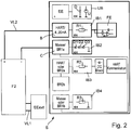
- Fig. 2 shows the assignment of the terminals A, B, C, Da, Db, E of the wireless adapter according to the invention for the case that a four-wire field device F2 is connected to the interface S of the wireless adapter.
- the field device F2 is supplied with energy by the external power supply unit EEext via the two connection lines VL1.
- the field device F2 is connected to the second connection terminal B and the third connection terminal C via the two connection lines VL2.
- the function of the terminal B and the downstream components has already been described in connection with Fig. 1 explained.
- the terminal C in this embodiment has the function of a ground terminal for the external power supply unit EEext.
- the maximum current flowing is limited by the current limit IB1.
- An additional polarity reversal protection consists of three series-connected diodes D1, D2, D3.
- the triple redundancy ensures that even if two of the three diodes fail, the protection is still working effectively.
- the diodes D1, D2, D3 furthermore have the effect that no internal capacitances or inductances act outward in the direction of the field device F2. The high safety requirements of explosion protection ex-ia are thus fulfilled.
- Fig. 3 shows occupancy of the terminals A, B, C, Da, Db, E of the wireless adapter according to the invention for the case that a two-wire field device F3 and an external power supply or an external power supply unit EEext are connected to the wireless adapter.
- the fourth terminal D is duplicated.
- the two terminals Da, Db functionally the same because they are connected to each other via a bridge Br2a, Br2b.
- the two-wire field device F3 is connected to the second connection terminal B and to the fourth connection terminal Db.
- the external power supply unit EEext is connected to the third terminal C and the fourth terminal Da.
- the wireless adapter and the field device F3 are powered by the external power supply unit EEext.
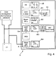
- Fig. 4 a first embodiment of the assignment of the terminals A, B, C, Da, Db, E of the wireless adapter according to the invention for the case shown that the wireless adapter works in a two-wire field device F1 in modem mode. Occupied in this embodiment, the fourth terminal Da and the fifth terminal E. The fifth terminal E, depending on the connected field installation F1, F2, EEext, BE to a high-impedance ground connection - which in the field installation of Fig. 4 the case is - or act around a bridge Br1 b, Br1a to the third terminal C.
- the wireless adapter is used in a two-wire field device F1 for modem operation
- the fourth terminal Da and the fifth terminal E are clamped on the two-wire line VL via the two communication lines KL.
- the two-wire line VL connects the two-wire field device F1 with the external power supply unit EEext and enables digital communication.
- Fig. 5 shows a second embodiment of the assignment of the terminals A, B, C, Da, Db, E of the wireless adapter according to the invention for the case that the wireless adapter works in modem mode in a four-wire field device F2.
- the power supply unit EEext which feeds the field device F2, is connected separately to the wireless adapter.
- the power supply unit EEext is connected to the third terminal C and the fourth terminal Da, in which case the third terminal C and the fifth terminal E via a bridge Br1 b, Br1 a are interconnected.
- the field device F2 is connected via the fourth connection terminal Db and the fifth connection terminal E to the wireless adapter.
- Fig. 6 the assignment of the terminals A, B, C, Da, Db, E of the wireless adapter according to the invention is shown for the case that an operating unit BE is connected to the wireless adapter.
- the operating unit BE is used, for example, for parameterizing the wireless adapter. It can also be used for commissioning or for diagnostic purposes.
- the control unit BE is connected to the wireless adapter or to the interface of the wireless adapter via the fourth terminal Da, ie the second communication terminal, and the fifth terminal E, which serves as a ground terminal.
Description
Die Erfindung betrifft eine universelle Schnittstelle für einen Wireless Adapter, der ein in der Automatisierungstechnik gebräuchliches Kommunikationsprotokoll unterstützt, wobei dem Wireless Adapter eine erste Energieversorgungseinheit zur Energieversorgung des Wireless Adapters und ein Funkmodul zur Kommunikation mit einer übergeordneten Steuereinheit über ein Funknetzwerk zugeordnet sind.The invention relates to a universal interface for a wireless adapter, which supports a communication protocol used in automation technology, wherein the wireless adapter is assigned a first power supply unit for supplying power to the wireless adapter and a radio module for communicating with a higher-level control unit via a radio network.
In der Prozessautomatisierungstechnik werden vielfach Feldgeräte eingesetzt, die zur Erfassung und/oder Beeinflussung von Prozessgrößen dienen. Zur Erfassung von Prozessgrößen dienen Sensoren, wie beispielsweise Füllstandsmessgeräte, Durchflussmessgeräte, Druck- und Temperaturmessgeräte, pH-Redoxpotentialmessgeräte, Leitfähigkeitsmessgeräte, etc., welche die entsprechenden Prozessvariablen Füllstand, Durchfluss, Druck, Temperatur, pH-Wert bzw. Leitfähigkeit erfassen. Zur Beeinflussung von Prozessgrößen dienen Aktoren, wie zum Beispiel Ventile oder Pumpen, über die der Durchfluss einer Flüssigkeit in einem Rohrleitungsabschnitt bzw. der Füllstand in einem Behälter geändert werden kann. Als Feldgeräte werden im Prinzip alle Geräte bezeichnet, die prozessnah eingesetzt werden und die prozessrelevante Informationen liefern oder verarbeiten. Neben den zuvor genannten Sensoren und Aktoren werden als Feldgeräte allgemein auch solche Einheiten bezeichnet, die direkt an einem Feldbus angeschlossen sind und zur Kommunikation mit den übergeordneten Einheiten dienen, wie z.B. Remote I/Os, Gateways, Linking Devices und Wireless Adapters. Eine Vielzahl solcher Feldgeräte wird von der Endress + Hauser-Gruppe hergestellt und vertrieben. Dokument
Neben einer drahtgebundenen Datenübertragung zwischen den Feldgeräten und der übergeordneten Einheit besteht auch die Möglichkeit einer drahtlosen (wireless) Datenübertragung. Insbesondere in den Bussystemen Profibus®, Foundation® Fieldbus und HART® ist eine drahtlose Datenübertragung über Funk spezifiziert. Ferner sind Funknetzwerke für Sensoren in dem Standard IEEE 802.15.4 näher spezifiziert. Zur Realisierung einer drahtlosen Datenübertragung sind neuere Feldgeräte, insbesondere Sensoren und Aktoren, teilweise als Funk-Feldgeräte ausgebildet. Diese weisen in der Regel eine Funkeinheit und eine Stromquelle als integrale Bestandteile auf. Dabei können die Funkeinheit und die Sromquelle in dem Feldgerät selbst oder in einem dauerhaft an dem Feldgerät angeschlossenen Funkmodul vorgesehen sein. Durch die Stromquelle wird eine autarke Energieversorgung des Feldgerätes ermöglicht.In addition to a wired data transmission between the field devices and the parent unit, there is also the possibility of wireless (wireless) data transmission. Especially in the bus systems Profibus®, Foundation® Fieldbus and HART® wireless data transmission via radio is specified. Furthermore, radio networks for sensors are further specified in the IEEE 802.15.4 standard. In order to realize a wireless data transmission, newer field devices, in particular sensors and actuators, are partly designed as radio field devices. These usually have a radio unit and a power source as integral components. In this case, the radio unit and the power source may be provided in the field device itself or in a radio module permanently connected to the field device. The power source enables a self-sufficient power supply of the field device.
Daneben besteht die Möglichkeit, Feldgeräte ohne Funkeinheiten - also die installierte Basis - durch die Kopplung mit jeweils einem Wireless Adapter, der eine Funkeinheit aufweist, zu einem Funk-Feldgerät aufzurüsten. Ein entsprechender Wireless Adapter ist beispielsweise in der Druckschrift
Bei autarken Funk-Feldgeräten und Wireless Adaptern wird die Kommunikation, beispielsweise mit einer übergeordneten Einheit, in der Regel über die drahtlose Schnittstelle des Funk-Feldgerätes bzw. des Wireless Adapters abgewickelt. Zusätzlich weisen solche Funk-Feldgeräte bzw. Wireless Adapter in der Regel eine drahtgebundene Kommunikationsschnittstelle auf. Beispielsweise ist in dem HART®-Standard vorgesehen, dass Funk-Feldgeräte neben einer drahtlosen Schnittstelle auch eine drahtgebundene Kommunikationsschnittstelle aufweisen müssen. Über solch eine drahtgebundene Kommunikationsschnittstelle ist beispielsweise vor Ort eine Konfiguration des Funk-Feldgerätes bzw. des Wireless Adapters über eine Service- und/oder Bedieneinheit, wie beispielsweise einen Handheld Communicator, die/der an der drahtgebundenen Kommunikationsschnittstelle angeschlossen wird, möglich. Ferner kann die drahtgebundene Kommunikationsschnittstelle als Feldbus-Kommunikationsschnittstelle ausgebildet sein, so dass die Kommunikation darüber entsprechend einem Bussystem, wie beispielsweise entsprechend einem der standardisierten Bussysteme Profibus®, Foundation® Fieldbus oder HART®, abgewickelt wird. Über solch eine Feldbus-Kommunikationsschnittstelle kann das Funk-Feldgerät bzw. der Wireless Adapter auch an einen entsprechenden drahtgebundenen Feldbus angeschlossen werden.In self-sufficient radio field devices and wireless adapters, the communication, for example, with a higher-level unit, usually handled by the wireless interface of the radio field device or the wireless adapter. In addition, such radio field devices or wireless adapters usually have a wired communication interface. For example, it is provided in the HART® standard that radio field devices must not only have a wireless interface but also a wired communication interface. About such a wired communication interface, for example, a configuration of the wireless field device or the wireless adapter via a service and / or operating unit, such as a handheld communicator, which is connected to the wired communication interface, for example, possible. Furthermore, the wired communication interface can be designed as a fieldbus communication interface, so that the communication about it is handled according to a bus system, such as according to one of the standard bus systems Profibus®, Foundation® Fieldbus or HART®. Via such a fieldbus communication interface, the radio field device or the wireless adapter can also be connected to a corresponding wired fieldbus.
Die Energieversorgungseinheit bzw. die Stromquelle eines Wireless Adapters oder eines Funk-Feldgerätes ist beispielsweise eine in dem Wireless Adapter bzw. dem Funk-Feldgerät vorgesehene Batterie, eine Brennstoffzelle, eine solare Energieversorgung und/oder ein Akku.The power supply unit or the power source of a wireless adapter or a radio field device, for example, one in the wireless adapter or the radio field device provided battery, a fuel cell, a solar power supply and / or a battery.
In der installierten Basis finden sich die unterschiedlichsten Typen von Feldinstallationen: Eine Vielzahl der Feldgeräte sind als 4-20mA Feldgeräte ausgestaltet. Hier repräsentiert der analoge 4-20mA-Stromwert den Messwert. Zusätzlich kann dem Stromsignal eine digitale Kommunikation überlagert sein, die üblicherweise - was jedoch keine Beschränkung darstellt - auf dem HART Protokoll basiert. Unter den Begriff der 'Feldinstallation' lassen sich neben den Zweidraht-Feldgeräten natürlich auch Vierdraht-Feldgeräte subsumieren; weiterhin fallen unter den Begriff Bediengeräte, die beispielsweise zur Parametrierung des Wireless Adapters verwendet werden, oder auch die Verwendung des Wireless Adapters im Modembetrieb.The installed base contains the most diverse types of field installations: a large number of field devices are designed as 4-20mA field devices. Here, the analog 4-20mA current value represents the measured value. In addition, the current signal may be overlaid with a digital communication, which is usually - but not limited - based on the HART protocol. Of course, four-wire field devices can also be subsumed under the term "field installation" in addition to the two-wire field devices; Furthermore, the term HMI devices, which are used, for example, to parameterize the wireless adapter, or also the use of the wireless adapter in modem operation.
Ein Wireless Adapter, der zumindest für ein in der Automatisierungstechnik gebräuchliches Protokoll zur digitalen Kommunikation ausgelegt ist, ist üblicherweise auf die spezielle Feldinstallation zugeschnitten. Bei der bekannten Lösung fehlt die notwendige Flexibilität, um den Wireless Adapter bei unterschiedlichen Feldinstallationen anzuwenden. Es liegt auf der Hand, dass die herkömmlichen Lösungen daher sehr aufwändig zu realisieren sind.A wireless adapter, which is designed at least for a commonly used in automation technology protocol for digital communication, is usually tailored to the specific field installation. The known solution lacks the necessary flexibility to use the wireless adapter in different field installations. It is obvious that the conventional solutions are therefore very complex to implement.
Der Erfindung liegt die Aufgabe zugrunde, eine universelle Schnittstelle für einen Wireless Adapter vorzuschlagen, die flexible Anschlussmöglichkeiten unterschiedlicher Feldinstallationen an einen Wireless Adapter ermöglicht.The invention has for its object to provide a universal interface for a wireless adapter that allows flexible connection options of different field installations to a wireless adapter.
Die Aufgabe wird dadurch gelöst, dass an der Schnittstelle zumindest fünf Anschlussklemmen vorgesehen sind, die so ausgestaltet sind, dass in Abhängigkeit von der jeweils anzuschließenden Feldinstallation jeweils eine Teilmenge der Anschlussklemmen entweder mit unterschiedlichen Ausgestaltungen von Feldgeräten oder mit einem Bediengerät verbindbar ist. Unter dem Begriff 'Feldinstallation' sind die unterschiedlich ausgelegte Typen von Feldgeräten zu verstehen, also Zweidraht- oder Vierdraht-Feldgeräte; erfindungsgemäß umfasst werden aber auch Bediengeräte, die beispielsweise zur Parametrierung des Wireless Adapters verwendet werden. Eine weitere wichtige Anwendung ist die Nutzung des Wireless Adapters im Modembetrieb. Durch Mehrfachnutzung von Anschlussklemmen bei unterschiedlichen Feldinstallationen lässt sich die Anzahl der Anschlussklemmen erheblich reduzieren bzw. minimieren. Insbesondere wird durch die innere Beschaltung der Anschlussklemmen erreicht, dass verschiedene Anschlussklemmen je nach Applikation unterschiedliche Funktionen aufweisen und in unterschiedlichen Kombinationen mit den Feldinstallationen verbunden werden. Es wird hier also ein flexibles Anschlusskonzept für einen Wireless Adapter beschrieben, das es erlaubt, unterschiedliche Sensoren/Messumformer einfach anzuschließen, bzw. den Wireless Adapter einfach in bestehende Applikationen einzubinden, bzw. vom Kunden gewünschte, spezielle Verschaltungen zu realisieren.The object is achieved in that at least five terminals are provided on the interface, which are designed so that depending on the respective field installation to be connected in each case a subset of the terminals is connectable either with different configurations of field devices or with an operator panel. The term 'field installation' is understood to mean the differently designed types of field devices, ie two-wire or four-wire field devices; However, according to the invention, operating devices which are used, for example, for parameterizing the wireless adapter are also included. Another important application is the use of the wireless adapter in modem mode. By multiple use of terminals in different field installations, the number of terminals can be significantly reduced or minimized. In particular, it is achieved by the internal wiring of the terminals that different terminals have different functions depending on the application and are connected in different combinations with the field installations. Thus, a flexible connection concept for a wireless adapter is described here, which makes it easy to connect different sensors / transmitters, or simply integrate the wireless adapter into existing applications, or to realize customer-specific, special interconnections.
Eine vorteilhafte Ausgestaltung der erfindungsgemäßen Schnittstelle schlägt vor, dass es sich bei der ersten Anschlussklemme um eine Energieversorgungsklemme handelt, an die die Energieversorgungseinheit angeschlossen ist.An advantageous embodiment of the interface according to the invention suggests that the first terminal is a power supply terminal to which the power supply unit is connected.
Darüber hinaus ist vorgesehen, dass es sich bei der zweiten Anschlussklemme um eine erste Kommunikationsklemme handelt, die die digitale Kommunikation entsprechend dem Kommunikationsprotokoll und/oder die Ermittlung des analogen Stromsignals unterstützt. Das Kommunikationsprotokoll unterstützt bevorzugt den HART Standard, da HART Feldgeräte in der Automatisierungstechnik die größte Verbreitung aufweisen. Es versteht sich von selbst, dass auch andere in der Automatisierungstechnik gebräuchliche Kommunikationsprotokolle unterstützt werden können. Ggf. sind dann weitere Anschlussklemmen vorzusehen. Beispielhaft sind neben dem HART-Protokoll, das Profibus Protokoll oder das Foundation Fieldbus Protokoll zu nennen.In addition, it is provided that the second connection terminal is a first communication terminal which supports the digital communication according to the communication protocol and / or the determination of the analog current signal. The communication protocol preferably supports the HART standard, since HART field devices are most widely used in automation technology. It goes without saying that other common in automation technology communication protocols can be supported. Possibly. then provide additional terminals. Examples include the HART protocol, the Profibus protocol or the Foundation Fieldbus protocol.
Erfolgt die Messwertbestimmung konventionell mittels eines analogen Stromsignals, so wird bevorzugt das 4-20mA Signal verwendet, da sich dieser Standard in der Prozessautomatisierungstechnik durchgesetzt hat.If the measured value is determined conventionally by means of an analog current signal, the 4-20 mA signal is preferably used, since this standard has prevailed in process automation technology.
Gemäß einer ersten Ausgestaltung der erfindungsgemäßen Schnittstelle wird ein von der Energieversorgungseinheit des Wireless Adapters gespeistes Zweidraht-Feldgerät, bei dem die Energieversorgung und die Bereitstellung des Messwerts über dieselbe Zweidrahtleitung erfolgen, an die erste Anschlussklemme und an die zweite Anschlussklemme angeschlossen. Die Energieversorgung des Feldgeräts erfolgt in diesem Fall über die in der Schnittstelle integrierte Energieversorgungseinheit. Bei der Energieversorgungseinheit handelt es sich beispielsweise um eine Batterie, ein Solarpanel, einen Akku oder eine Brennstoffzelle.According to a first embodiment of the interface according to the invention, a two-wire field device fed by the energy supply unit of the wireless adapter, in which the power supply and the provision of the measured value take place via the same two-wire line, is connected to the first connection terminal and to the second connection terminal. The power supply of the field device takes place in this case via the integrated power supply unit in the interface. The energy supply unit is, for example, a battery, a solar panel, a rechargeable battery or a fuel cell.
Eine vorteilhafte Ausgestaltung der erfindungsgemäßen Schnittstelle sieht eine dritten Anschlussklemme vor, bei der es sich je nach anzuschließender Feldinstallation entweder um eine Masseklemme für eine externe Energieversorgungseinheit oder um eine Brücke handelt, die die Verbindung zur fünften Anschlussklemme herstellt, die im Nachfolgenden noch näher beschrieben wird.An advantageous embodiment of the interface according to the invention provides for a third terminal, which, depending on the field installation to be connected, is either a ground terminal for an external power supply unit or a bridge which establishes the connection to the fifth terminal, which will be described in more detail below.
Gemäß einer vorteilhaften Ausgestaltung der erfindungsgemäßen Schnittstelle ist ein Vierdraht-Feldgerät, das über eine erste Zweidrahtleitung und eine externe Energieversorgungseinheit mit Energie versorgt ist, über die zweite Anschlussklemme und die dritte Anschlussklemme mit dem Wireless Adapter verbunden. Somit werden in Abhängigkeit von der jeweiligen Feldinstallation das digitale Kommunikationssignal und/oder das den Messwert repräsentierende Stromsignal über die an der zweiten Anschlussklemme und an der dritten Anschlussklemme des Wireless Adapters angeklemmte zweite Zweidrahtleitung übertragen.According to an advantageous embodiment of the interface according to the invention, a four-wire field device, which is supplied with energy via a first two-wire line and an external power supply unit, is connected to the wireless adapter via the second connection terminal and the third connection terminal. Thus, depending on the particular field installation, the digital communication signal and / or the current signal representing the measured value are transmitted via the second two-wire line clamped to the second connection terminal and to the third connection terminal of the wireless adapter.
Darüber hinaus ist vorgesehen, dass es sich bei einer vierten Anschlussklemme um eine zweite Kommunikationsklemme handelt, die die digitale Kommunikation entsprechend dem jeweiligen Kommunikationsprotokoll der Feldinstallation unterstützt.In addition, it is provided that a fourth connection terminal is a second communication terminal which supports digital communication in accordance with the respective communication protocol of the field installation.
Als vorteilhaft wird es darüber hinaus angesehen, wenn die vierte Anschlussklemme zweifach ausgeführt ist bzw. wenn die beiden Anschlussklemmen funktional gleich arbeiten, da sie über eine Brücke miteinander verbunden sind.It is also considered advantageous if the fourth terminal is made in duplicate or if the two terminals work functionally the same, since they are connected to each other via a bridge.
Gemäß einer vorteilhaften Weiterbildung der erfindungsgemäßen Schnittstelle wird vorgeschlagen, dass für den Fall, dass ein Zweidraht-Feldgerät und eine externe Energieversorgungseinheit separat an den Wireless Adapter anzuschließen sind, das Zweidraht-Feldgerät an die zweite Anschlussklemme und an die vierte Anschlussklemme angeschlossen ist und dass die externe Energieversorgungseinheit mit der dritten Anschlussklemme und der vierten Anschlussklemme verbunden ist.According to an advantageous development of the interface according to the invention, it is proposed that in the event that a two-wire field device and an external power supply unit are to be connected separately to the wireless adapter, the two-wire field device is connected to the second terminal and to the fourth terminal and that external power supply unit is connected to the third terminal and the fourth terminal.
Weiterhin ist vorgesehen, dass es sich bei einer fünften Anschlussklemme je nach angeschlossener Feldinstallation entweder um einen hochohmigen Masseanschluss oder um eine Brücke zur dritten Anschlussklemme handelt.Furthermore, it is provided that there is a fifth terminal depending on the connected field installation is either a high-impedance ground terminal or a bridge to the third terminal.
Als vorteilhaft wird es im Zusammenhang mit der vorliegenden Erfindung erachtet, wenn für den Fall, dass der Wireless Adapter bei einem Zweidraht-Feldgerät für den Modembetrieb verwendet wird, die vierte Anschlussklemme und die fünfte Anschlussklemme über die beiden Kommunikationsleitungen auf die Zweidrahtleitung, die das Zweidraht-Feldgerät mit der externen Energieversorgungseinheit verbindet und über die die digitale Kommunikation erfolgt, angeschlossen ist.It is considered advantageous in the context of the present invention if, in the case where the wireless adapter is used in a two-wire field device for modem operation, the fourth connection terminal and the fifth connection terminal via the two communication lines on the two-wire line, the two-wire Field device connects to the external power supply unit and via which the digital communication takes place.
Für den Fall, dass der Wireless Adapter bei einem über die externe Energieversorgungseinheit gespeisten Feldgerät im Modembetrieb arbeitet, ist vorgesehen, dass die externe Energieversorgungseinheit mit der dritten Anschlussklemme und der vierten Anschlussklemme verbunden ist, wobei die dritte Anschlussklemme und die fünfte Anschlussklemme über eine Brücke miteinander verbunden sind, und wobei das Feldgerät über die vierte Anschlussklemme und die fünfte Anschlussklemme an den Wireless Adapter angeschlossen ist.In the event that the wireless adapter works in modem mode with a field device powered by the external power supply unit provided that the external power supply unit is connected to the third terminal and the fourth terminal, wherein the third terminal and the fifth terminal are connected via a bridge, and wherein the field device via the fourth terminal and the fifth terminal is connected to the wireless adapter ,
Wie bereits gesagt, lässt das sich der Wireless Adapter über die Schnittstelle zwecks Parametrierung oder Diagnose auch mit einem Bediengerät verbinden. Hierbei wird das Bediengerät an die vierte Anschlussklemme und die fünfte Anschlussklemme angeschlossen.As already mentioned, the wireless adapter can also be connected to an HMI device via the interface for parameterization or diagnostics. The HMI device is connected to the fourth connection terminal and the fifth connection terminal.
Um den erfindungsgemäßen Wireless Adapter uneingeschränkt und damit auch im Explosionsgefährdeten Bereich einsetzen zu können, wird vorgeschlagen, dass jeder der Anschlussklemmen entweder eine Spannungsbegrenzung und/oder Strombegrenzung zugeordnet ist, die so ausgelegt sind, dass beim Anschluss der jeweiligen Feldinstallation an den Wireless Adapter die zur Verfügung stehende Leistung so bemessen ist, dass der Einsatz des Wireless Adapters in Verbindung mit der Feldinstallation im Explosionsgefährdeten Bereich möglich ist. insbesondere ist bei allen Applikationsmöglichkeiten der Explosionsschutz gewährleistet. Insbesondere ist auch bei fehlerhaftem Anschluss der Feldinstallation an den Wireless Adapter ausgeschlossen, dass die für den Explosionsgefährdeten Bereich maximal zulässige Leistungsübertragung überschritten wird.In order to use the wireless adapter according to the invention without restriction and thus in the hazardous area, it is proposed that each of the terminals is assigned either a voltage limit and / or current limiting, which are designed so that when connecting the respective field installation to the wireless adapter for Available power is such that the use of the wireless adapter in connection with the field installation in potentially explosive areas is possible. In particular, the explosion protection is guaranteed in all applications. In particular, even if the field installation to the wireless adapter is incorrectly connected, it is excluded that the maximum permissible power transmission for the potentially explosive area is exceeded.
Die Erfindung wird anhand der nachfolgenden Figuren näher erläutert. Es zeigt:
-
Fig. 1 : die Belegung der Anschlussklemmen des erfindungsgemäßen Wireless Adapters im Falle des Anschlusses eines Feldgeräts, das über den Wireless Adapter mit Energie versorgt wird, -
Fig. 2 : die Belegung der Anschlussklemmen des erfindungsgemäßen Wireless Adapters für den Fall, dass ein Vierdraht-Feldgerät an den Wireless Adapter angeschlossen ist, -
Fig. 3 : die Belegung der Anschlussklemmen des erfindungsgemäßen Wireless Adapters für den Fall, dass ein Zweidraht-Feldgerät und ein externes Netzteil an den Wireless Adapter angeschlossen sind, -
Fig. 4 : eine erste Ausgestaltung der Belegung der Anschlussklemmen des erfindungsgemäßen Wireless Adapters für den Fall, dass der Wireless Adapter im Modembetrieb bei einem Zweidraht-Feldgerät arbeitet, -
Fig. 5 : eine zweite Ausgestaltung der Belegung der Anschlussklemmen des erfindungsgemäßen Wireless Adapters für den Fall, dass der Wireless Adapter im Modembetrieb bei einem Vierdraht-Feldgerät arbeitet und -
Fig. 6 : die Belegung der Anschlussklemmen des erfindungsgemäßen Wireless Adapters für den Fall, dass ein Bediengerät an den Wireless Adapter angeschlossen ist.
-
Fig. 1 : the assignment of the terminals of the wireless adapter according to the invention in the case of the connection of a field device, which is powered by the wireless adapter, -
Fig. 2 : the assignment of the terminals of the wireless adapter according to the invention in the event that a four-wire field device is connected to the wireless adapter, -
Fig. 3 : the assignment of the terminals of the wireless adapter according to the invention in the event that a two-wire field device and an external power supply are connected to the wireless adapter, -
Fig. 4 a first embodiment of the assignment of the terminals of the wireless adapter according to the invention for the case that the wireless adapter works in modem operation in a two-wire field device, -
Fig. 5 a second embodiment of the assignment of the terminals of the wireless adapter according to the invention for the case that the wireless adapter works in modem operation in a four-wire field device and -
Fig. 6 : the assignment of the terminals of the wireless adapter according to the invention in the event that an HMI device is connected to the wireless adapter.
In den Figuren
Die je nach angeschlossener Feldinstallation aktiven Komponenten der Schnittstelle S sind in den Figuren
Der Wireless Adapter, der in den Figuren nicht explizit dargestellt ist, weist darüber hinaus ein Funkmodul FM auf, das die drahtlose Kommunikation mit einer übergeordneten Steuereinheit ST über das Funknetzwerk FN ermöglicht.The wireless adapter, which is not explicitly shown in the figures, moreover has a radio module FM, which enables wireless communication with a higher-level control unit ST via the radio network FN.
Bei dem Feldgerät F1 handelt es sich somit um ein Zweidraht-Feldgerät. Zweidraht-Feldgeräte zeichnen sich dadurch aus, dass die Energieversorgung und die Übermittlung des Messwerts, z.B. eines 4-20mA-Messwerts und/oder die digitale Kommunikation über dieselbe Zweidrahtleitung VL erfolgen.The field device F1 is thus a two-wire field device. Two-wire field devices are characterized in that the power supply and the transmission of the measured value, e.g. of a 4-20mA reading and / or digital communication over the same two-wire line VL.
Bei der ersten Anschlussklemmen A, die als Pluspol dient, handelt es sich um die Energieversorgungsklemme, an die die Energierversorgungseinheit EE des Wireiess Adapters angeschlossen ist. Bei der zweiten Anschlussklemme B handelt es sich um eine erste Kommunikationsklemme, die entweder die digitale Kommunikation entsprechend dem jeweiligen Kommunikationsprotokoll, z.B. dem HART-Protokoll, und/oder die die Ermittlung des analogen Stromsignals, insbesondere eines 4-20 mA-Stromsignals unterstützt.The first terminal A, which serves as a positive pole, is the power supply terminal to which the power supply unit EE of the Wireiess adapter is connected. The second connection terminal B is a first communication terminal which either supports the digital communication according to the respective communication protocol, eg the HART protocol, and / or the determination of the analog current signal, in particular a 4-20 mA current signal.
Zur Sicherstellung des Ex-Schutzes ist zu der Energieversorgungseinheit EE eine Spannungsbegrenzung UB parallel geschaltet. Durch die parallel zur Spannungsquelle U geschaltete Diode D wird eine Gleichspannung bereitgestellt, die maximal die Z-Spannung der Diode D (Sperrrichtung) erreichen kann. Der Betriebsspannung der Diode D in Durchlassrichtung entspricht. Die zweite Anschlussklemme B, die den Minuspol darstellt, weist aus Ex-Schutz-Gründen eine Strombegrenzung IB1 auf. Hier ist der Strom durch den Widerstand R1 begrenzt. Durch die Strom- und Spannungsbegrenzung wird sichergestellt, dass nur eine den Ex-Vorschriften genügende Leistung an den Anschlussklemmen A, B zur Verfügung gestellt wird.To ensure the explosion protection, a voltage limitation UB is connected in parallel with the energy supply unit EE. By the parallel to the voltage source U connected diode D, a DC voltage is provided, which can reach a maximum of the Z voltage of the diode D (reverse direction). The operating voltage of the diode D in the forward direction corresponds. The second terminal B, which represents the negative pole, has a current limit IB1 for explosion protection reasons. Here the current through the resistor R1 is limited. The current and voltage limitation ensures that only a power sufficient for the Ex regulations is provided at the terminals A, B.
Das analoge Stromsignal und/oder das HART-Signal werden/wird über die Funktionseinheit FE zu einem in der
In
Für den Fall, dass der Wireless Adapter bei einem Zweidraht-Feldgerät F1 für den Modembetrieb verwendet wird, sind die vierte Anschlussklemme Da und die fünfte Anschlussklemme E über die beiden Kommunikationsleitungen KL auf die Zweidrahtleitung VL aufgeklemmt. Die Zweidrahtleitung VL verbindet das Zweidraht-Feldgerät F1 mit der externen Energieversorgungseinheit EEext und ermöglicht die digitale Kommunikation.In the event that the wireless adapter is used in a two-wire field device F1 for modem operation, the fourth terminal Da and the fifth terminal E are clamped on the two-wire line VL via the two communication lines KL. The two-wire line VL connects the two-wire field device F1 with the external power supply unit EEext and enables digital communication.
In
Claims (15)
- Universal interface (S) for a wireless adapter which supports a communication protocol (HART) commonly used in automation engineering, wherein a first energy supply unit (2) for the provision of energy to the wireless adapter and a wireless module (FM) for communicating with a higher-level control unit (ST) via a radio network (FN) are assigned to the wireless adapter, wherein at least five terminals (A, B, C, D, E) are provided at the interface (S), said terminals being designed in such a way that, depending on the field installation to be connected (F1, F2, EEext, BE), a subset of the terminals (A, B, C, D, E) can be connected either to different embodiments of field devices (F1, F2) or to an operating unit (BE), or the wireless adapter can be used in modem mode,
and wherein the assignment of the terminals (A, B, C, D, E) changes depending on the field installation and the individual terminals (A, B, C, D, E) can be used in different combinations. - Interface as claimed in Claim 1, wherein the first terminal (A) is an energy supply terminal which is connected to an energy supply unit (EE).
- Interface as claimed in Claim 1, wherein the second terminal (B) is a first communication terminal that supports digital communication in accordance with the communication protocol (HART) and/or the determination of the analog current signal (4-20 mA).
- Interface as claimed in Claim 2 or 3, wherein a two-wire field device (F1), which is powered by the energy supply unit (EE) of the wireless adapter where energy is supplied and the measured value is provided via the same two-wire cable (VL), can be connected to the first terminal (A) and the second terminal (B).
- Interface as claimed in Claim 1, wherein, depending on the field installation to be connected (F1, F2, EEext, BE), the third terminal (C) is a ground terminal for an external energy supply unit (EEext) or a bridge (Br1 a, Br1 b) that establishes the connection to the fifth terminal (E).
- Interface as claimed in Claim 3 and 5, wherein a four-wire field device (F2) which is supplied with energy via a first two-wire cable (VL2) and an external energy supply unit (EEext) can be connected to the wireless adapter via the second (B) terminal and the third terminal (C) such that the digital communication signal and/or the current signal representing the measured value can be transmitted via the second two-wire cable (VL2) connected to the second terminal (B) and the third terminal (C).
- Interface as claimed in Claim 1, wherein the fourth terminal (D) is a second communication terminal that supports digital communication according to the communication protocol (HART).
- Interface as claimed in Claim 7, wherein the fourth terminal (D) is duplicated or wherein the two terminals (Da, Db) are identical in terms of function as they are interconnected via a bridge (Br2a, Br2b).
- Interface as claimed in Claim 3, 5 or 7, wherein if a two-wire field device (F1) and an external energy supply unit (EEext) are to be connected separately to the wireless adapter, then the two-wire field device (F1) is connected to the second terminal (B) and to the fourth terminal (Db) and the external energy supply unit (EEext) is connected to the third terminal (C) and the fourth terminal (Da).
- Interface as claimed in Claim 1, wherein, depending on the field installation connected (F1, F2, EEext, BE), the fifth terminal (E) is a high-impedance ground connection or a bridge (Br1 b, Br1 a) to the third terminal (C).
- Interface as claimed in one or more of Claims 7 or 8 and 10, wherein, if the wireless adapter is used for the modem mode in the case of a two-wire field device (F1), the fourth terminal (Da) and the fifth terminal (E) are connected via the two communication lines (KL) to the two-wire cable (VL), which connects the two-wire field device (F1) to the external energy supply unit (EEext) and via which digital communication takes place.
- Interface as claimed in Claim 5, 7 and 10, wherein, if the wireless adapter operates in modem mode in the case of a field device (F2) that is powered via the external energy supply unit (EEext), the external energy supply unit (EEext) is connected to the third terminal (C) and the fourth terminal (Da), wherein the third terminal (C) and the fifth terminal (E) are interconnected via a bridge (Br1a, Br1b), and wherein the field device (F2) is connected to the wireless adapter via the fourth terminal (Db) and the fifth terminal (E).
- Interface as claimed in Claim 7 and 10, wherein, if the wireless adapter is operated using an operating device (BE), the operating device (BE) can be connected to the fourth terminal (Da) and the fifth terminal (E).
- Interface as claimed in one or more of the previous claims, wherein each of the terminals (A, B, C, D, E) is assigned either a voltage limitation (UB) and/or a current limitation (IB), which are designed in such a way that when the field installation (F1, F2, EEext, BE) is connected to the wireless adapter the level of power provided is such that it is possible to use the wireless adapter in conjunction with the field installation (F1, F2, EEext, BE) in the explosion hazardous area.
- Interface as claimed in Claim 1, wherein the communication protocol is the HART protocol, the Profibus protocol or the Foundation Fieldbus protocol.
Applications Claiming Priority (2)
| Application Number | Priority Date | Filing Date | Title |
|---|---|---|---|
| DE200810036967 DE102008036967A1 (en) | 2008-08-08 | 2008-08-08 | Universal interface for a wireless adapter |
| PCT/EP2009/060031 WO2010015601A1 (en) | 2008-08-08 | 2009-08-03 | Universal interface for a wireless adapter |
Publications (2)
| Publication Number | Publication Date |
|---|---|
| EP2307934A1 EP2307934A1 (en) | 2011-04-13 |
| EP2307934B1 true EP2307934B1 (en) | 2018-06-20 |
Family
ID=41258305
Family Applications (1)
| Application Number | Title | Priority Date | Filing Date |
|---|---|---|---|
| EP09781421.4A Active EP2307934B1 (en) | 2008-08-08 | 2009-08-03 | Universal interface for a wireless adapter |
Country Status (6)
| Country | Link |
|---|---|
| US (1) | US8902801B2 (en) |
| EP (1) | EP2307934B1 (en) |
| CN (1) | CN102112932B (en) |
| CA (1) | CA2732935C (en) |
| DE (1) | DE102008036967A1 (en) |
| WO (1) | WO2010015601A1 (en) |
Families Citing this family (18)
| Publication number | Priority date | Publication date | Assignee | Title |
|---|---|---|---|---|
| DE102009047535B4 (en) * | 2009-12-04 | 2023-12-07 | Endress + Hauser Process Solutions Ag | Method for determining a connection configuration of a field device on a wireless adapter |
| DE102011076708A1 (en) | 2011-05-30 | 2012-12-06 | Endress + Hauser Process Solutions Ag | Radio unit with a supply circuit for power supply and method for operating such a radio unit |
| DE102011076706A1 (en) | 2011-05-30 | 2012-12-06 | Endress + Hauser Process Solutions Ag | Electrical and / or electronic power supply circuit and method for providing a supply voltage |
| DE102011086396A1 (en) * | 2011-11-15 | 2013-05-16 | Endress + Hauser Wetzer Gmbh + Co Kg | Method for transferring data between field device of process automation technology and remote data processing device, involves catching data retrieved from field device when transmitting to remote data processing device |
| DE102012012431A1 (en) * | 2012-06-25 | 2014-01-02 | Robert Bosch Gmbh | Communication apparatus e.g. smartphone for establishing communication between field and hand control devices, has changing unit to adjust received data according to protocol transfer partially supported by field or hand control device |
| DE102012111018A1 (en) * | 2012-11-15 | 2014-05-15 | Systemplan GmbH | Multichannel measurement data acquisition device for microprocessor-controlled data recording, comprises input channels operatively connected to data storage unit, and power supply unit for providing input channels with supply voltages |
| DE102012112635A1 (en) * | 2012-12-19 | 2014-06-26 | Endress+Hauser Process Solutions Ag | Radio module for a field device |
| DE102014000679A1 (en) * | 2014-01-22 | 2015-07-23 | Phoenix Contact Gmbh & Co. Kg | Connection adapter system of the control technology |
| DE102014105913A1 (en) | 2014-04-28 | 2015-10-29 | Phoenix Contact Gmbh & Co. Kg | Parameterizable power supply unit |
| CN105488977A (en) * | 2015-12-08 | 2016-04-13 | 上海工业自动化仪表研究院 | On-site meter self-powered wireless adaptive system |
| DE102017114851A1 (en) * | 2017-07-04 | 2019-01-10 | Endress+Hauser SE+Co. KG | Field device adapter for wireless data transmission |
| DE102017121923B4 (en) * | 2017-09-21 | 2019-12-19 | Vega Grieshaber Kg | Measuring arrangement with an operating device and method for operating such a measuring arrangement |
| DE102018110101A1 (en) * | 2018-04-26 | 2019-10-31 | Endress+Hauser SE+Co. KG | Plug-in radio module of automation technology |
| JP7192290B2 (en) | 2018-07-27 | 2022-12-20 | 横河電機株式会社 | Communication equipment and systems |
| DE102018122014A1 (en) | 2018-09-10 | 2020-03-12 | Endress + Hauser Flowtec Ag | Measuring system and measuring arrangement thus formed |
| DE102018131685A1 (en) * | 2018-12-11 | 2020-06-18 | Endress+Hauser SE+Co. KG | Field device adapter for wireless data transmission |
| DE102019125150A1 (en) | 2019-09-18 | 2021-03-18 | Endress + Hauser Wetzer Gmbh + Co. Kg | Field device |
| DE102020105605A1 (en) * | 2020-03-03 | 2021-09-09 | Endress+Hauser SE+Co. KG | Field device adapter for wireless data transmission |
Citations (1)
| Publication number | Priority date | Publication date | Assignee | Title |
|---|---|---|---|---|
| EP1925918A2 (en) * | 2006-11-27 | 2008-05-28 | VEGA Grieshaber KG | Connection box for transmission of a signal |
Family Cites Families (12)
| Publication number | Priority date | Publication date | Assignee | Title |
|---|---|---|---|---|
| US7228186B2 (en) * | 2000-05-12 | 2007-06-05 | Rosemount Inc. | Field-mounted process device with programmable digital/analog interface |
| DE10113676A1 (en) * | 2001-03-21 | 2002-09-26 | Abb Research Ltd | System has plug connectors enabling optional connections between sensor or actuator and configuration/diagnosis/maintenance unit or communications module and between module and unit |
| US7035773B2 (en) * | 2002-03-06 | 2006-04-25 | Fisher-Rosemount Systems, Inc. | Appendable system and devices for data acquisition, analysis and control |
| CA2433314C (en) * | 2002-08-23 | 2007-03-27 | Firemaster Oilfield Services Inc. | Apparatus system and method for gas well site monitoring |
| US7096073B2 (en) * | 2003-09-22 | 2006-08-22 | Creo Il, Ltd. | Configurable controller |
| DE602005026631D1 (en) | 2004-03-02 | 2011-04-14 | Rosemount Inc | PROCESSED DEVICE INSTALLED WITH PROGRAMMABLE DIGITAL / ANALOG INTERFACE |
| DE102004020393A1 (en) * | 2004-04-23 | 2005-11-10 | Endress + Hauser Gmbh + Co. Kg | Radio module for field devices of automation technology |
| US8538560B2 (en) * | 2004-04-29 | 2013-09-17 | Rosemount Inc. | Wireless power and communication unit for process field devices |
| JP4792851B2 (en) * | 2004-11-01 | 2011-10-12 | 横河電機株式会社 | Field equipment |
| US7421531B2 (en) * | 2005-01-12 | 2008-09-02 | Rosemount Inc. | Isolating system that couples fieldbus data to a network |
| DE102006055900B4 (en) * | 2005-12-27 | 2011-08-25 | VEGA Grieshaber KG, 77709 | Interface Adapter |
| WO2007118656A1 (en) * | 2006-04-12 | 2007-10-25 | Vega Grieshaber Kg | Transceiver for wire-free transmission of field device signals |
-
2008
- 2008-08-08 DE DE200810036967 patent/DE102008036967A1/en not_active Withdrawn
-
2009
- 2009-08-03 CA CA2732935A patent/CA2732935C/en active Active
- 2009-08-03 WO PCT/EP2009/060031 patent/WO2010015601A1/en active Application Filing
- 2009-08-03 CN CN200980130736.8A patent/CN102112932B/en active Active
- 2009-08-03 US US12/451,952 patent/US8902801B2/en active Active
- 2009-08-03 EP EP09781421.4A patent/EP2307934B1/en active Active
Patent Citations (1)
| Publication number | Priority date | Publication date | Assignee | Title |
|---|---|---|---|---|
| EP1925918A2 (en) * | 2006-11-27 | 2008-05-28 | VEGA Grieshaber KG | Connection box for transmission of a signal |
Also Published As
| Publication number | Publication date |
|---|---|
| CN102112932A (en) | 2011-06-29 |
| WO2010015601A1 (en) | 2010-02-11 |
| EP2307934A1 (en) | 2011-04-13 |
| CN102112932B (en) | 2013-12-25 |
| CA2732935A1 (en) | 2010-02-11 |
| DE102008036967A1 (en) | 2010-02-11 |
| US20110134817A1 (en) | 2011-06-09 |
| CA2732935C (en) | 2016-09-20 |
| US8902801B2 (en) | 2014-12-02 |
Similar Documents
| Publication | Publication Date | Title |
|---|---|---|
| EP2307934B1 (en) | Universal interface for a wireless adapter | |
| EP1860513B1 (en) | Connection for secure transmission of an analogue signal value | |
| DE102010037262B4 (en) | Integrated bus control and power supply device for use in a process control system | |
| EP2984530B1 (en) | Measuring transducer feed unit, system for use in automation technology, and method for operating such a system | |
| DE102012014681B4 (en) | Use of a lO link for connecting a power supply unit | |
| DE102011006590B4 (en) | Method for operating a gateway | |
| EP2307931B1 (en) | Independent field device or independent wireless adapter for a field device in automation technology | |
| CH702454A1 (en) | Arrangement with a superordinate control unit and at least one connected with the control unit intelligent field device. | |
| EP3025318B1 (en) | Measuring instrument having a switchable measuring and operating electronics system for transmitting a measurement signal | |
| WO2013178210A1 (en) | Field bus system | |
| WO2010049253A1 (en) | Self-contained field device | |
| EP3170287A1 (en) | Control and data-transfer system, gateway module, i/o module, and method for process control | |
| EP3283928B1 (en) | Method for automatically connecting or disconnecting a communication resistor of a hart device | |
| WO2011067070A2 (en) | Method for determining a connection configuration of a field device to a wireless adapter | |
| WO2017202675A1 (en) | Wireless adapter for a field device, comprising an antenna for two communication standards | |
| DE102011086054B4 (en) | System for ensuring the availability of a bus system in automation technology | |
| WO2018184766A1 (en) | Power-over-ethernet-based field device used in automation technology | |
| EP3821308A1 (en) | Terminal module, head module, and system for collecting data from an automation system | |
| DE102009054800A1 (en) | Arrangement for application-specific processing and accessing of device-specific information of e.g. pump utilized in factory automation technology, is designed such that selected parameter subgroup is made available in structure | |
| EP2316195A1 (en) | Apparatus for controlling a field device which is linked into a radio network for automation engineering | |
| EP3153938B1 (en) | Measuring apparatus | |
| WO2021239350A1 (en) | Field device for checking the quality of a network connection | |
| DE102012110999A1 (en) | Method for operating display unit for displaying process data, involves communicating display unit in terms of field bus protocol with control unit, where display unit is connected over field bus at control unit | |
| DE202013100798U1 (en) | Universal control unit with BUS and WEB connection |
Legal Events
| Date | Code | Title | Description |
|---|---|---|---|
| PUAI | Public reference made under article 153(3) epc to a published international application that has entered the european phase |
Free format text: ORIGINAL CODE: 0009012 |
|
| 17P | Request for examination filed |
Effective date: 20110113 |
|
| AK | Designated contracting states |
Kind code of ref document: A1 Designated state(s): AT BE BG CH CY CZ DE DK EE ES FI FR GB GR HR HU IE IS IT LI LT LU LV MC MK MT NL NO PL PT RO SE SI SK SM TR |
|
| AX | Request for extension of the european patent |
Extension state: AL BA RS |
|
| RIN1 | Information on inventor provided before grant (corrected) |
Inventor name: FIEDLER, MARC Inventor name: PROBST, STEFAN |
|
| DAX | Request for extension of the european patent (deleted) | ||
| 17Q | First examination report despatched |
Effective date: 20160414 |
|
| RAP1 | Party data changed (applicant data changed or rights of an application transferred) |
Owner name: ENDRESS+HAUSER PROCESS SOLUTIONS AG |
|
| GRAP | Despatch of communication of intention to grant a patent |
Free format text: ORIGINAL CODE: EPIDOSNIGR1 |
|
| INTG | Intention to grant announced |
Effective date: 20180212 |
|
| GRAS | Grant fee paid |
Free format text: ORIGINAL CODE: EPIDOSNIGR3 |
|
| GRAA | (expected) grant |
Free format text: ORIGINAL CODE: 0009210 |
|
| AK | Designated contracting states |
Kind code of ref document: B1 Designated state(s): AT BE BG CH CY CZ DE DK EE ES FI FR GB GR HR HU IE IS IT LI LT LU LV MC MK MT NL NO PL PT RO SE SI SK SM TR |
|
| REG | Reference to a national code |
Ref country code: GB Ref legal event code: FG4D Free format text: NOT ENGLISH |
|
| REG | Reference to a national code |
Ref country code: IE Ref legal event code: FG4D Free format text: LANGUAGE OF EP DOCUMENT: GERMAN |
|
| REG | Reference to a national code |
Ref country code: AT Ref legal event code: REF Ref document number: 1011043 Country of ref document: AT Kind code of ref document: T Effective date: 20180715 |
|
| REG | Reference to a national code |
Ref country code: DE Ref legal event code: R096 Ref document number: 502009015043 Country of ref document: DE |
|
| REG | Reference to a national code |
Ref country code: FR Ref legal event code: PLFP Year of fee payment: 10 |
|
| REG | Reference to a national code |
Ref country code: NL Ref legal event code: FP |
|
| PG25 | Lapsed in a contracting state [announced via postgrant information from national office to epo] |
Ref country code: NO Free format text: LAPSE BECAUSE OF FAILURE TO SUBMIT A TRANSLATION OF THE DESCRIPTION OR TO PAY THE FEE WITHIN THE PRESCRIBED TIME-LIMIT Effective date: 20180920 Ref country code: SE Free format text: LAPSE BECAUSE OF FAILURE TO SUBMIT A TRANSLATION OF THE DESCRIPTION OR TO PAY THE FEE WITHIN THE PRESCRIBED TIME-LIMIT Effective date: 20180620 Ref country code: BG Free format text: LAPSE BECAUSE OF FAILURE TO SUBMIT A TRANSLATION OF THE DESCRIPTION OR TO PAY THE FEE WITHIN THE PRESCRIBED TIME-LIMIT Effective date: 20180920 Ref country code: LT Free format text: LAPSE BECAUSE OF FAILURE TO SUBMIT A TRANSLATION OF THE DESCRIPTION OR TO PAY THE FEE WITHIN THE PRESCRIBED TIME-LIMIT Effective date: 20180620 Ref country code: FI Free format text: LAPSE BECAUSE OF FAILURE TO SUBMIT A TRANSLATION OF THE DESCRIPTION OR TO PAY THE FEE WITHIN THE PRESCRIBED TIME-LIMIT Effective date: 20180620 |
|
| REG | Reference to a national code |
Ref country code: LT Ref legal event code: MG4D |
|
| PG25 | Lapsed in a contracting state [announced via postgrant information from national office to epo] |
Ref country code: LV Free format text: LAPSE BECAUSE OF FAILURE TO SUBMIT A TRANSLATION OF THE DESCRIPTION OR TO PAY THE FEE WITHIN THE PRESCRIBED TIME-LIMIT Effective date: 20180620 Ref country code: HR Free format text: LAPSE BECAUSE OF FAILURE TO SUBMIT A TRANSLATION OF THE DESCRIPTION OR TO PAY THE FEE WITHIN THE PRESCRIBED TIME-LIMIT Effective date: 20180620 Ref country code: GR Free format text: LAPSE BECAUSE OF FAILURE TO SUBMIT A TRANSLATION OF THE DESCRIPTION OR TO PAY THE FEE WITHIN THE PRESCRIBED TIME-LIMIT Effective date: 20180921 |
|
| PG25 | Lapsed in a contracting state [announced via postgrant information from national office to epo] |
Ref country code: IS Free format text: LAPSE BECAUSE OF FAILURE TO SUBMIT A TRANSLATION OF THE DESCRIPTION OR TO PAY THE FEE WITHIN THE PRESCRIBED TIME-LIMIT Effective date: 20181020 Ref country code: EE Free format text: LAPSE BECAUSE OF FAILURE TO SUBMIT A TRANSLATION OF THE DESCRIPTION OR TO PAY THE FEE WITHIN THE PRESCRIBED TIME-LIMIT Effective date: 20180620 Ref country code: PL Free format text: LAPSE BECAUSE OF FAILURE TO SUBMIT A TRANSLATION OF THE DESCRIPTION OR TO PAY THE FEE WITHIN THE PRESCRIBED TIME-LIMIT Effective date: 20180620 Ref country code: RO Free format text: LAPSE BECAUSE OF FAILURE TO SUBMIT A TRANSLATION OF THE DESCRIPTION OR TO PAY THE FEE WITHIN THE PRESCRIBED TIME-LIMIT Effective date: 20180620 Ref country code: CZ Free format text: LAPSE BECAUSE OF FAILURE TO SUBMIT A TRANSLATION OF THE DESCRIPTION OR TO PAY THE FEE WITHIN THE PRESCRIBED TIME-LIMIT Effective date: 20180620 Ref country code: SK Free format text: LAPSE BECAUSE OF FAILURE TO SUBMIT A TRANSLATION OF THE DESCRIPTION OR TO PAY THE FEE WITHIN THE PRESCRIBED TIME-LIMIT Effective date: 20180620 |
|
| PG25 | Lapsed in a contracting state [announced via postgrant information from national office to epo] |
Ref country code: SM Free format text: LAPSE BECAUSE OF FAILURE TO SUBMIT A TRANSLATION OF THE DESCRIPTION OR TO PAY THE FEE WITHIN THE PRESCRIBED TIME-LIMIT Effective date: 20180620 Ref country code: ES Free format text: LAPSE BECAUSE OF FAILURE TO SUBMIT A TRANSLATION OF THE DESCRIPTION OR TO PAY THE FEE WITHIN THE PRESCRIBED TIME-LIMIT Effective date: 20180620 |
|
| REG | Reference to a national code |
Ref country code: DE Ref legal event code: R097 Ref document number: 502009015043 Country of ref document: DE |
|
| PG25 | Lapsed in a contracting state [announced via postgrant information from national office to epo] |
Ref country code: MC Free format text: LAPSE BECAUSE OF FAILURE TO SUBMIT A TRANSLATION OF THE DESCRIPTION OR TO PAY THE FEE WITHIN THE PRESCRIBED TIME-LIMIT Effective date: 20180620 |
|
| REG | Reference to a national code |
Ref country code: CH Ref legal event code: PL |
|
| PLBE | No opposition filed within time limit |
Free format text: ORIGINAL CODE: 0009261 |
|
| STAA | Information on the status of an ep patent application or granted ep patent |
Free format text: STATUS: NO OPPOSITION FILED WITHIN TIME LIMIT |
|
| PG25 | Lapsed in a contracting state [announced via postgrant information from national office to epo] |
Ref country code: CH Free format text: LAPSE BECAUSE OF NON-PAYMENT OF DUE FEES Effective date: 20180831 Ref country code: LI Free format text: LAPSE BECAUSE OF NON-PAYMENT OF DUE FEES Effective date: 20180831 Ref country code: LU Free format text: LAPSE BECAUSE OF NON-PAYMENT OF DUE FEES Effective date: 20180803 |
|
| REG | Reference to a national code |
Ref country code: BE Ref legal event code: MM Effective date: 20180831 |
|
| 26N | No opposition filed |
Effective date: 20190321 |
|
| REG | Reference to a national code |
Ref country code: IE Ref legal event code: MM4A |
|
| PG25 | Lapsed in a contracting state [announced via postgrant information from national office to epo] |
Ref country code: DK Free format text: LAPSE BECAUSE OF FAILURE TO SUBMIT A TRANSLATION OF THE DESCRIPTION OR TO PAY THE FEE WITHIN THE PRESCRIBED TIME-LIMIT Effective date: 20180620 |
|
| PG25 | Lapsed in a contracting state [announced via postgrant information from national office to epo] |
Ref country code: IE Free format text: LAPSE BECAUSE OF NON-PAYMENT OF DUE FEES Effective date: 20180803 |
|
| PG25 | Lapsed in a contracting state [announced via postgrant information from national office to epo] |
Ref country code: BE Free format text: LAPSE BECAUSE OF NON-PAYMENT OF DUE FEES Effective date: 20180831 Ref country code: SI Free format text: LAPSE BECAUSE OF FAILURE TO SUBMIT A TRANSLATION OF THE DESCRIPTION OR TO PAY THE FEE WITHIN THE PRESCRIBED TIME-LIMIT Effective date: 20180620 |
|
| REG | Reference to a national code |
Ref country code: AT Ref legal event code: MM01 Ref document number: 1011043 Country of ref document: AT Kind code of ref document: T Effective date: 20180803 |
|
| PG25 | Lapsed in a contracting state [announced via postgrant information from national office to epo] |
Ref country code: AT Free format text: LAPSE BECAUSE OF NON-PAYMENT OF DUE FEES Effective date: 20180803 |
|
| PG25 | Lapsed in a contracting state [announced via postgrant information from national office to epo] |
Ref country code: MT Free format text: LAPSE BECAUSE OF FAILURE TO SUBMIT A TRANSLATION OF THE DESCRIPTION OR TO PAY THE FEE WITHIN THE PRESCRIBED TIME-LIMIT Effective date: 20180620 |
|
| PG25 | Lapsed in a contracting state [announced via postgrant information from national office to epo] |
Ref country code: TR Free format text: LAPSE BECAUSE OF FAILURE TO SUBMIT A TRANSLATION OF THE DESCRIPTION OR TO PAY THE FEE WITHIN THE PRESCRIBED TIME-LIMIT Effective date: 20180620 |
|
| PG25 | Lapsed in a contracting state [announced via postgrant information from national office to epo] |
Ref country code: PT Free format text: LAPSE BECAUSE OF FAILURE TO SUBMIT A TRANSLATION OF THE DESCRIPTION OR TO PAY THE FEE WITHIN THE PRESCRIBED TIME-LIMIT Effective date: 20180620 Ref country code: HU Free format text: LAPSE BECAUSE OF FAILURE TO SUBMIT A TRANSLATION OF THE DESCRIPTION OR TO PAY THE FEE WITHIN THE PRESCRIBED TIME-LIMIT; INVALID AB INITIO Effective date: 20090803 |
|
| PG25 | Lapsed in a contracting state [announced via postgrant information from national office to epo] |
Ref country code: CY Free format text: LAPSE BECAUSE OF FAILURE TO SUBMIT A TRANSLATION OF THE DESCRIPTION OR TO PAY THE FEE WITHIN THE PRESCRIBED TIME-LIMIT Effective date: 20180620 Ref country code: MK Free format text: LAPSE BECAUSE OF NON-PAYMENT OF DUE FEES Effective date: 20180620 |
|
| P01 | Opt-out of the competence of the unified patent court (upc) registered |
Effective date: 20230601 |
|
| PGFP | Annual fee paid to national office [announced via postgrant information from national office to epo] |
Ref country code: NL Payment date: 20230821 Year of fee payment: 15 |
|
| PGFP | Annual fee paid to national office [announced via postgrant information from national office to epo] |
Ref country code: IT Payment date: 20230825 Year of fee payment: 15 Ref country code: GB Payment date: 20230822 Year of fee payment: 15 |
|
| PGFP | Annual fee paid to national office [announced via postgrant information from national office to epo] |
Ref country code: FR Payment date: 20230824 Year of fee payment: 15 Ref country code: DE Payment date: 20230821 Year of fee payment: 15 |