EP2242029A1 - Device for singulating and testing coins - Google Patents
Device for singulating and testing coins Download PDFInfo
- Publication number
- EP2242029A1 EP2242029A1 EP09005508A EP09005508A EP2242029A1 EP 2242029 A1 EP2242029 A1 EP 2242029A1 EP 09005508 A EP09005508 A EP 09005508A EP 09005508 A EP09005508 A EP 09005508A EP 2242029 A1 EP2242029 A1 EP 2242029A1
- Authority
- EP
- European Patent Office
- Prior art keywords
- rotor
- coins
- coin
- flap
- opening
- Prior art date
- Legal status (The legal status is an assumption and is not a legal conclusion. Google has not performed a legal analysis and makes no representation as to the accuracy of the status listed.)
- Granted
Links
Images


Classifications
-
- G—PHYSICS
- G07—CHECKING-DEVICES
- G07D—HANDLING OF COINS OR VALUABLE PAPERS, e.g. TESTING, SORTING BY DENOMINATIONS, COUNTING, DISPENSING, CHANGING OR DEPOSITING
- G07D9/00—Counting coins; Handling of coins not provided for in the other groups of this subclass
- G07D9/008—Feeding coins from bulk
-
- G—PHYSICS
- G07—CHECKING-DEVICES
- G07D—HANDLING OF COINS OR VALUABLE PAPERS, e.g. TESTING, SORTING BY DENOMINATIONS, COUNTING, DISPENSING, CHANGING OR DEPOSITING
- G07D3/00—Sorting a mixed bulk of coins into denominations
- G07D3/14—Apparatus driven under control of coin-sensing elements
Definitions
- the invention relates to a device for separating and testing of coins, comprising a housing with a collecting container which can accommodate a plurality of different coins unsorted, arranged in the housing and in an inclined plane rotatably driven rotor with at least one coin receiving, wherein the rotor Collecting container passes through a rotation with its at least one coin holder, so that coins located in the container individually taken from the at least one coin holder and guided along a circular path, and at least one characteristic properties of the coin-testing sensor device, on the at least one coin holder recorded Coins are passed by the rotation of the rotor.
- Such devices are increasingly placed at cash registers of supermarkets or the like. But they are also used, for example, at toll stations or in buses. A customer can then conveniently pay at the payment machine equipped with the device by displaying his coin money, e.g. a handful of coins, as a loose amount in a throw-in tank there. After inserting a quantity of coins into the collection container, the device starts automatically or externally and separates the quantity of coins. It then feeds the coins to a sensor device to identify their type and value. This saves time and simplifies the payment process.
- a device which represents a complete coin deposit and coin payout system.
- the coins are first separated in a separating device and then fed from the separating device of a test device in which the coins are checked for their authenticity and their value.
- Out GB 2 356 966 A Furthermore, a device for separating and checking coins is known, in which coins located in a collecting container are picked up individually by a rotating disc having a corresponding coin receptacle and, in the course of its rotation with the disc, are guided past a sensor device for checking the coins. In the direction of rotation of the coins, the sensor device is followed by an output opening. This has a controllable ramp.
- the known devices have in common that the coins are led out after their isolation in each case by a first or second discharge opening from the device. As misrecognized or unrecognized coins are then directly to returned to the customer. If a denied coin is genuine, the customer must reinsert this coin one or more times. Nevertheless, in order to ensure a comfortable use of the device for the customer, the strigsensorik must be adjusted accordingly wide to prevent that too large a quantity of genuine coins is judged to be wrong. This often leads to misjudgments where false coins are judged genuine.
- the present invention seeks to provide a device of the type mentioned above, which allows in a simple, compact and convenient for the customer to check coins more precisely and to minimize misjudgments.
- the invention solves the problem in that a selection device is provided which is controlled by a control device in response to a test result of the sensor device for a coin so that this coin is either fed to a dispensing opening or that this coin is again passed by the rotor to the sensor device.
- the rotor plane is inclined relative to the vertical in the mounted state of the device.
- the rotor may, for example, be disc-shaped, for example in the form of a pay-out disc. In particular, it has a plurality of coin holders. These can be arranged one behind the other, for example, in the direction of rotation of the rotor. The rotor passes through the unsorted in the collecting container unsorted amount of coins and reaches out with the coins coins.
- the sensor device may comprise one or more sensors and also be arranged in the housing.
- the sensors can eg detect physical properties of the coins, eg material, thickness, diameter, etc.
- the controller can determine the authenticity and type of the coins.
- Such sensors are known per se.
- a coin or an object to be tested can rotate and be tested within the device until meaningful decision criteria have been found on the coin.
- the tests run concealed for the customer in particular.
- a precise coin check is possible, whereby misjudgments are minimized.
- the device works more reliably and has a higher customer friendliness.
- Such coins must be collected separately and then withdrawn from circulation. This is also possible with the device according to the invention.
- the dispensing opening may branch into at least a first dispensing line for accepted coins and at least one second dispensing line for unaccepted coins, wherein a guide element which can also be activated by the control device in response to a check result of the coin sensor means is provided which either opens the dispensing opening connects to the first output line or to the second output line.
- the dispensing opening thus opens into at least two output lines, eg output shafts. Due to the guide element as a switch, the coins dispensed from the coin holders are separated into acceptable and unacceptable coins.
- the guide member may also be a flap.
- the second output line for unaccepted coins may, for example, result in a return in which the coins are returned to the customer.
- the first output line can branch further into several lines or containers in which the accepted For example, coins may be sorted by their recognized value or fitness.
- the output lines may include sensors (eg, optical sensors or metal sensors) that monitor whether the coins have been fed into the correct output line.
- the selection device can have a flap which can be opened and closed by the control device as a function of the test result of the sensor device, wherein the flap closes the dispensing opening in the closed state and releases the dispensing opening in the opened state, so that one of the Rotor can slide over the dispensing opening guided coin by gravity into the dispensing opening.
- the flap and the output opening closed or released by the latter are thus arranged so that coins held in the coin holders are guided over the flap or the discharge opening during the rotation of the rotor. In the closed state of the flap they can slide over the flap, while they fall in the open state of the flap in the discharge opening.
- the activation of the valves provided according to the invention can be effected, for example, magnetically, in particular by spring-loaded tension magnets. It may further be provided that the flap of the selection device and / or the guide element of the discharge opening in the resting state, that is, e.g. in a non-energized state of a driving magnet, e.g. be kept open by a spring preload. In this way, in the event of a defect of a driver, it is ensured that the container is emptied and coins contained therein are returned to the customer. The closing of the flaps then takes place by actuation of a control element against the bias.
- an inclined base plate can be arranged in the housing, on which the rotor rotates, wherein the discharge opening is provided in the base plate, and the outlet opening occlusive or releasing flap is pivotally mounted on the base plate. It may also be provided a second, identical to the first flap of the selector except for their position flap. The two flaps may, for example, be arranged mirror-symmetrically to the vertical running through the rotor center. Devices, such as are provided according to the invention, are followed by other devices during operation, eg return devices for returning coins as change to a customer.
- the devices in this case may have to be arranged on different sides, for example a cashier station, a corresponding space is often also available for the devices connected to them only on one or the other side of the device. Therefore, it may be necessary to rotate the rotor in a clockwise or counterclockwise direction, depending on the arrangement of the device. Therefore, the flap must be arranged either on one or the other side of the device. During operation, the unneeded flap can be kept permanently closed.
- Other components of the device such as the dispensing opening and output lines, can be provided twice and each on one side of the device. In fact, all devices can be arranged mirrored except for the drive motor of the rotor. In this way, the device is flexibly prepared for a wide variety of operational uses. However, it is also possible, for example, to arrange the dispensing opening and dispensing lines centrally on the device, so that only one dispensing opening is suitable for any use of the device.
- the at least one coin holder of the rotor can be at least one pocket-shaped recess.
- the pockets may have a circular shape open on one side. They are formed passing through the rotor plane, so that the coins held in them on an example can slide under the rotor provided base plate.
- the rotor may have a plurality of pocket-shaped recesses of different sizes, wherein at least one of the larger recesses in its region facing the rotor center has an opening which has a smaller size than the respective larger recess.
- the additional opening may in particular have a smaller cross-section than the diameter of a respective larger, substantially circular recess.
- the additional opening may be, for example, slit-shaped.
- the different bag sizes are provided for coins of different sizes.
- the larger coins can not be held in the small pockets.
- the smaller coins may initially be picked up in the large pockets, they will fall out again through a suitable opening in these pockets. This opening is smaller than the diameter of the recess, so that larger held in the recesses coins can not fall out.
- the recess can continue to run in its center facing the rotor center V-shaped.
- V-shaped configuration By such a V-shaped configuration, the coins are held securely in the recording during their rotation, wherein movements of the coins are minimized. This increases the measurement accuracy by the sensor device.
- an imaginary, emanating from the top of the V-shape and extending through the center of the circular basic shape of the recess line at an angle to a likewise imaginary, extending from the rotor center in the radial direction of the rotor plane through the center of the circular basic shape Line runs.
- the angle can be, for example, about 7.5 °.
- the sensor device can also be arranged starting from the rotor center in the radial direction of the rotor, the radial connecting the rotor center to the sensor device at an angle to the direction of the rotor Gravity acting on the coins is that coins carried by the rotor first pass through the highest point of their circular path and are then guided past the sensor device.
- the angle can be for example 12.5 °.
- the pockets are thus aligned obliquely in this embodiment with respect to the radial direction.
- the sensor device is arranged in an example counter-clockwise rotating rotor in the range between the 9 and 12 o'clock position. By contrast, in the case of a clockwise rotating rotor, the sensor device is provided between the 12 o'clock and the 3 o'clock position.
- the sensor device can be arranged in the region of the 11 o'clock position or in the region of the 1 o'clock position.
- the center of the sensor module is thus slightly rotated relative to the vertical. This has the advantage that coins that are located twice in the pockets, first pass through the highest point of their orbit and thereby have sufficient time to fall back due to the inclination of the rotor level in the sump. This ensures that the coins pass through the sensor device sporadically. It is also conceivable to arrange the sensor device at 12 o'clock position, but with the disadvantage that the coins located twice in the pockets have less time to fall back.
- the pockets themselves are inclined relative to the vertical.
- a measuring range of an optical sensor for example a light barrier
- an exit from this measuring range for example a second light barrier
- both small and large coins are stable in position in the coin holders.
- a diameter measurement with optical detection by means of light barriers is subject to errors. Especially when with the device different coins in a large diameter range must be processed, this is of great importance.
- the rotor may have a thickening in at least one region delimiting the opening of a pocket-shaped recess, in particular its peripheral region.
- the thickening may be triangular in cross-section, for example.
- the thickening is thus provided at the edge of the opening of at least one, in particular all Münztaschen. It may in particular be provided on the trailing edge in the direction of rotation of the rotor of the pocket opening. But it is also possible to additionally or alternatively provide at the opening leading edge such a thickening.
- the thickening causes, with only a few coins in the collecting container, especially in the case of the last coin still contained in the container, a faster picking up of the coin into the pocket.
- the thickening when passing through the collecting container causes a stirring effect, which improves the coin receiving especially for a few coins contained in the collecting container.
- a further improvement of the positional stability of the coins in the coin holders is achieved if the control device is designed to drive the rotor in a continuously rotating manner.
- a sensor may be provided which detects when coins are in the sump.
- Such a sensor may e.g. be an optical or metal sensor.
- the control device can then set the rotor in rotation for operation. The rotor is rotated continuously. This results in less vibration and thus to a minimization of the sensor measurements falsifying coin movements.
- the closable dispensing opening also has the advantage that the disc without Start / Stop operation can be operated to ensure a continuous and thus more precise measurement of the coins. If the rotor disc rotates continuously, the next following coin recognized as genuine may not yet be sorted into the dispensing opening, because a pre-paid coin previously accepted may still be in the processing area and cause system obstruction. In this case, the dispensing opening is closed by means of the movable flap and the next coin is returned to the container. The rotor disk therefore does not need to stop if another coin is not to be sorted into the acceptance area. Only when it is certain that a next coin can be reliably processed, the discharge opening is released again.
- the collecting container may have on its underside a waste flap which can be opened and closed manually and / or actuated by a motor, so that objects located in the collecting container fall by gravity into a waste opening.
- the waste flap allows unwanted items to be removed from the sump. They can then be directed eg into a separate waste container or returned to the customer. If the opening and closing of the flap takes place by motor, for example, after each completed transaction, the waste flap can be opened in order to remove foreign objects still present in the container. Alternatively or additionally, a manual actuation of the flap, for example by a customer possible.
- the waste flap can have an end position detection device with which a waste opening completely closing the final position of the waste flap is detectable.
- the end position detection may include, for example, a device for monitoring the rotation of a flap closing motor, with which in particular the number of rotations of the engine is counted. It is also possible to count with a suitable device, the rotations of other when closing the flap rotating components, such as a Exzenterrades. On the basis of the counted revolutions can be determined in each case, whether the flap is completely closed or not. Also, it can be determined on the basis of the counted revolutions, whether the waste flap has reached the maximum opening.
- the end position of the waste flap can be detected by an optical light barrier in that only in this end position, the flap itself or a suitable, for example, in the position firmly connected lever activates a sensor.
- the sensor can be a light barrier, reed contact, Hall sensor, etc.
- a groove may further be provided on the housing, into which a waste opening closing edge of the waste flap is inserted in the closed state of the waste flap.
- the waste flap may be locked in its closed position against accidental opening. The lock is then automatically released by a manual or motorized opening of the flap.
- the sensor device can have any sensors for testing the coins.
- optical sensors for example, optical sensors, metal sensors, electromagnetic sensors, etc.
- Such sensors are known per se.
- the sensor device can have two optical sensors, each time points of entering and leaving a coin in and out of a measuring range of the optical sensors.
- the optical sensors may, for example, have lasers or other suitable light sources which form light barriers which are respectively opened and closed by the coins as they pass through the sensor device. In each case, the opening and closing of the light barriers is detected, the diameter of the respective coin can be determined with knowledge of the rotational speed of the rotor. If two optical sensors are provided, which each time the entry and exit of a coin, four times are recorded.
- Devices such as are provided according to the invention, are fastened to carriers during operation. It may therefore be provided according to a further embodiment, that the device is locked or latched with its housing on a mounting plate.
- the mounting plate may have previously been screwed in a simple manner on the carrier.
- a lock e.g. Locking lever, in particular two locking levers, be provided which lock when placing the device on the mounting plate.
- latching locking elements e.g. Snap hook, in question, which lock on reaching the end position of the device on the mounting plate.
- the advantage of this embodiment is that the device can be mounted in a simple manner and can also be dismantled in a simple manner for maintenance and service purposes again.
- a device according to the invention for separating and checking coins is shown in various representations.
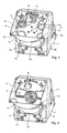
- a housing 12 of the device is shown with a collection container 14 provided at the lower end of the housing 12 into which a plurality of different coins are inserted unsorted.
- the housing 12 is at its in Fig. 1 to be recognized front 16 inclined relative to the vertical.
- Within the housing 12 is a likewise inclined relative to the vertical base plate 18 which in Fig. 1 is partially covered by a disposed in the housing 12 and in the predetermined by the base plate 18 inclined plane rotatably driven rotor 20 is covered.
- the rotor 20 is thus driven in rotation about a rotation axis 22 inclined to the horizontal.
- Fig. 10 For the drive is an example in Fig. 10 to be recognized electric motor 24 is provided.
- Fig. 2 For example, the rotor 20 is not shown.
- the example in the FIGS. 1, 2 and 10 The device shown is fastened with its underside 26 on a support, as will be explained in more detail below.
- the rotor 20 has a plurality of, in the illustrated example six coin holders 28 in the form of pocket-shaped recesses 28.
- the pockets 28 have a circular basic shape and are formed at its the outer periphery of the rotor disc 20 remote end V-shaped tapered into a tip 30.
- 18 two flaps 32 are pivotally articulated in the base plate.
- the flaps 32 are located above each of a dispensing opening which branches into a first dispensing line for accepted coins and a second dispensing line for unaccepted coins. This will be explained below by means of Fig. 3 explained in more detail. In operation, only one of the two flaps 32 and correspondingly only one of the two discharge openings and output lines is used.
- the other flap 32 is permanently closed.
- the rotor 20 is rotated counterclockwise, so that in the Figures 1 and 2 right flap 32 is permanently closed.
- the rotor 20 passes through the coins contained in the collecting container 14 unsorted and takes them individually in the coin holders 28.
- Fig. 1 two coins 34 are shown in the receptacles 28.
- the sensor device 36 is arranged in the direction of rotation of the coins 34 following the vertex of the circular path described by the coins 34, so that the coins 34 first pass through the vertex of the circular path and then the sensor device 36.
- the sensor device has a size such that the sensor device 36 fits through the receptacle 28 of the rotor 20, so that the rotor disk 20 can be easily removed from the device for maintenance purposes.
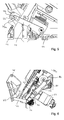
- the in the Figures 1 and 2 left flap 32 may by an example in Fig. 4 shown control device 38 (CPU-PCB) can be selectively opened and closed. This is an example in Fig. 3 to be detected magnetic drive element 40 is provided, which is controlled by the control device 38.
- CPU-PCB CPU-PCB
- the flap 32 can thereby from the in Fig. 3 shown open position are switched to the closed position, for example, not shown.
- a guided over the flap coin 34 falls into the released through the open flap 32 discharge opening 42, as shown in Fig. 3 can be seen.
- a further flap 46 which is mounted so as to be pivotable about a pivot axis 44, is arranged.
- the flap 46 is in particular in the region of a branch of the discharge opening 42 in a first output line 48 for accepted coins and a second output line 50 for unaccepted coins.
- a further magnetic drive element 52 is provided, which is also controlled by the control device 38.
- the flap 46 By driving the control element 52, the flap 46 can be pivoted about the pivot axis 44 and thus optionally the output port 42 with the first output line 48 or 50 are connected to the second output line.
- Two optical sensors 54, 56 are provided in the region of the output lines 48, 50, which each interact with a prism 58, 60.
- the optical sensors 54, 56 respectively direct a light beam 55, 57 onto the prism 58, 60 associated therewith.
- the light beam 55, 57 is deflected and guided again to a corresponding optical sensor of the sensor devices 54, 56 , In this way, transmitter and receiver of the sensors 54, 56 can sit on an electronic circuit board.
- the corresponding light beam is interrupted. In this way it can be checked whether the coin 34 has actually fallen into the correct output 48, 50.
- the receiving shaft 48 is traversed by both light beams.
- the return shaft 50 is traversed only by one of the light beams. As a result, a direction detection can also be carried out for the acceptance shaft.
- the device further has a waste flap 62 at the bottom of the Collection container 14.
- the waste flap 62 is shown in the closed state.
- items can be emptied from the sump 14, as will be explained in more detail below.
- Fig. 3 shown opened state of the waste flap 62 still in the sump 14 located residual items by gravity down from the device.
- the flap 62 is pivotally mounted on the collecting container 14 via a pivot axis 78.
- the waste flap 62 according to the invention can be operated both manually and manually.
- For the motor actuation is an example in Fig. 3 to be recognized electric motor 68 is provided.
- a hand lever 70 is provided for manual operation.
- an associated with this motor lever 72 is actuated.
- a pivotally connected to the motor lever 72 transfer lever 74 is actuated, which in turn is pivotally connected to the waste flap 62.
- the waste flap 62 in the example in Fig. 6 shown open position moves.
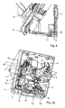
- the end position detection device 80 By an example in Fig. 8 shown end position detection device 80, the fully closed position of the waste flap 62 is monitored.
- the end position detection device has an optical sensor device which generates a light path which, when fully closed Flap 62 is interrupted, so that the end position can be determined.
- other types of end position detection devices are also conceivable, for example microswitches or inductively operating Hall sensors.
- the waste flap 62 is locked in its closed position against inadvertent opening by articles located in the collection container. This is an in Fig. 5 to be recognized locking 79 is provided, which cooperates with a bearing block 79 a, which is automatically unlocked at a motor or manual opening of the waste flap 62.
- the waste flap 62 can be actuated by the electric motor 68 by motor.
- the waste door 62 may then be automatically opened after each transaction to remove any debris still remaining in the sump 14.
- the motor 68 is connected via a gear 81 with an eccentric 82.
- the motor lever 72 is deflected as in a manual operation and the transfer door 74, the waste flap 62 is opened.
- the completely closed end position of the flap 62 can additionally or alternatively be effected by monitoring the eccentric wheel position, for example by a time loop in a microcontroller.
- the time is assumed in which the motor 68, the eccentric wheel 82 rotates once through 360 °. This time is dependent on the applied supply voltage of the motor 68. From this, the complete opening of the flap 62 can be derived, which should be reached after about 180 °. If the end position can not be found because, for example, foreign objects prevent the flap 62 from closing, the motor 24 for the rotor 20 can additionally be put into operation in order to remove the foreign bodies from the flap opening.
- the motor 68 itself is equipped with a position detection. For this purpose, for example, each revolution of a gear can be detected and counted. Such a procedure is very precise and independent of the applied supply voltage and any load conditions. Disadvantages are the higher costs associated with such a motor. Alternatively, a stepper motor can be used.
- the device is arranged with its underside 26 on a mounting plate 64. This can be screwed for example on a support for the device.
- the attachment of the housing 12 on the mounting plate 64 can be done in a particularly simple manner by locking or latching.
- a suitable locking element 66 is shown.
- Fig. 10 can also be constructed to a solution in which the rotor 20 rotates in the clockwise direction. All components of the device with the exception of the motor 24 for the rotor 20 can be mounted mirrored.
- Fig. 10 can also be seen that the pull magnets 40 and 52 are snapped for actuation of the flaps 32 and 46 in a simple manner via latching hooks 86 and can be correspondingly simply mirrored mounted in corresponding latching hooks 86.
- a turn-on sensor 84 can be seen.
- the turn-on sensor 84 may be, for example, an optical sensor or a metal sensor. It recognizes when objects, such as coins, are filled into the collection container 14.
- the power-on sensor 84 is connected to the controller 38 and signals the presence of coins. Thereafter, the controller 38 sets the motor 24 for the payout disc 20 in the counterclockwise direction in motion.
- the rotor 20 now fishes with the pockets 28 individual coins from the collecting container 14 and transports them past the sensor device 36.
- the control device 38 When passing through the sensor device 36 of these physical properties of the coins, such as material, thickness, diameter, etc., are detected. On this basis, the authenticity and the type of the coin 34 are determined by the control device 38. This sensor recognition is known per se to the person skilled in the art and will therefore not be explained further.
- the sensor device 36 can also be combined with other measuring devices in a manner known per se, if special features of the coin 34 are to be tested.
- the control device 38 does not actuate the actuation element 40 and thus the flap 32.
- the drive element 40 and the flap 32 thus remain in their rest position.
- the flap 32 In this rest position, the flap 32 is in the in Fig. 3 shown opened position in which it releases the discharge opening 42.
- the coin 34 therefore falls by gravity into the dispensing opening 42, as in Fig. 3 is shown.
- the control device 38 would have activated the actuation element 40 and thus the flap 32 closed.
- the coin 34 would have slipped over the flap 32 and again fed by the rotor 20 to the sensor device 36 for a second inspection. This can be repeated until a sufficient measurement basis for a decision on the authenticity of the coin is available.
- the controllable output flap 32 allows for continuous rotation of the pay-out disc motor 24 and thus the rotor 20. The continuous rotation of the motor 24 makes the sensor measurement more precise.
- the flap 32 remain closed.
- non-transportable residual items or slices that have not been sorted out are removed by opening the waste door 62.
- the waste cap 62 can be opened in the manner explained above, as in Fig. 3 is shown.
- the remaining in the sump 14 parts now fall by gravity down out of the device.
- the rotor 20 may be actuated by the motor 24 to remove any objects still in the pockets 28 of the rotor 20 or to release jammed objects in the device.
- the waste flap 62 is then closed again.
- the final position of the waste door 62 is detected via the end position sensor 80 to signal the proper operation of the device for the transaction.
- the waste flap 62 may also be operated via the manual hand lever 70.
- the rotor 20 has six pocket-shaped recesses 28 distributed uniformly around its circumference. It is also possible to provide a rotor 20 with pockets 28, 29 of different sizes, as shown in FIG FIG. 13 is shown by way of example. In the example shown, the rotor 20 has four smaller pockets 28 and two larger pockets 29. The number and size distribution of the pockets 28, 29 can of course also be chosen differently in a suitable manner. The pocket sizes are tuned so that larger coins in the smaller pockets 28 can not be accommodated.
- the larger pockets 29, on the other hand, are designed so that no two of the smallest coins of the currency to be tested can be held in one of the larger pockets 29.
- the larger pockets 29 each have a slot-shaped opening 29a, for example, on their side facing away from the rotor outer circumference.
- the openings 29 a are adapted in size to the diameter of the smaller pockets 28, that in the larger pockets 29 recorded coins to checking currency, which also fit into the smaller pockets 28 from their perimeter, through which openings 29a pass out of the larger pockets 29.
- larger coins do not fit through the openings 29a and are securely held in the larger pockets 29. *** " In this way, it is ensured that only the coin sizes intended for these pockets 28, 29 are received in the pockets 28, 29.
- the rotor 20 has in its the openings 28a of the recesses 28, 29 each bounding areas a thickening.
- a thickening for one of the recesses 28 at the reference numeral 108 shown hatched.
- the thickening 108 is provided at the edge of the opening 28 a of the coin pockets 28, 29.
- the rotor 20 rotates counterclockwise, so that the thickening 108 is provided on the trailing edge in the direction of rotation of the rotor 20 of the pocket opening 28a.
- each leading edges of the rotor 20 may be provided a thickening.
- Fig. 12 Based on Fig. 12 the arrangement of the sensor device will be explained in more detail. Of course, the sensor arrangement described below could also in the in Fig. 13 rotor 20 are provided. Exemplary are in Fig. 12 two optical sensors 88, 90 and a center of the sensor device 36 forming, for example, inductively operating material sensor 92 shown. First, it can be seen that the center of the sensor device 36 formed by the sensor 92, starting from the rotor center 94 along a radial 96 is arranged. The radial 96 extends at an angle ⁇ to the vertical 98 which simultaneously forms the direction of the force acting on the coins 34 gravity.
- the center of the sensor device 36 is rotated in the example shown by about 12.5 ° to the left, so that the coins located in the pockets 28 34 in a counterclockwise rotation of the rotor 20 first pass through the apex of their orbit and then the sensor device ,
- an imaginary line 102 extending from the apex 30 of the V-shape of the recesses 28 and through the center 100 of the circular basic shape of the pockets 28 is imaginary with respect to one passing radially from the rotor center 94 through the center 100 of the circular recess 28
- Line 104 is at an angle ⁇ .
- the angle ⁇ is about 7.5 °.
- the optical sensors 88, 90 each generate one perpendicular to the plane of the drawing Fig. 12 extending photocell. As they move, the coins 34 pass through both light barriers of the sensors 88 and 90 and also the centrally arranged material sensor 92. During this passage, the coins 34 in the openings 28 should as far as possible not move.
- the beginning of the diameter measurement of a coin 34 is shown.
- the end of the diameter measurement is shown.
- the optical sensors 88, 90 each measure the times at which the light barrier is interrupted and reopened.
- this measurement is plotted against the time t for the light barriers L1 and L2 of the optical sensors 88 and 90, respectively.
- the time offset between the respective measuring points t1 and t3 of the first measuring device 88 and t2 and t4 of the second measuring device 90 can be recognized.
- the curve L3 with the measuring points t1 and t2 can be determined from the curves L1 and L2. In this way, the diameter of the coins 34 can be determined in a conventional manner.
- the measuring signal of the material sensor is in Fig. 14 represented by the curve M.
- the highest accuracy is achieved when all four measurement points t1, t2, t3 and t4 are recorded. Then, a jerking of the rotor disk 20 is compensated in the course of the rotation.
- the measuring point t4 can be dispensed with. As a result, the measurement accuracy is only slightly reduced.
- control device 38 for evaluating the sensor results and for controlling the components of the device, in particular the rotor 20 and the flaps 32 and 46
- two control devices in the form of microprocessors are also provided in the figures with one device controlling the coin check and a second controlling the control flow and an external interface of the device.
Landscapes
- Physics & Mathematics (AREA)
- General Physics & Mathematics (AREA)
- Control Of Vending Devices And Auxiliary Devices For Vending Devices (AREA)
Abstract
Description
Die Erfindung betrifft eine Vorrichtung zum Vereinzeln und Prüfen von Münzen, umfassend ein Gehäuse mit einem Sammelbehälter, der eine Mehrzahl unterschiedlicher Münzen unsortiert aufnehmen kann, ein in dem Gehäuse angeordneter und in einer geneigten Ebene drehend antreibbarer Rotor mit mindestens einer Münzaufnahme, wobei der Rotor den Sammelbehälter bei einer Rotation mit seiner mindestens einen Münzaufnahme durchläuft, so dass in dem Sammelbehälter befindliche Münzen einzeln von der mindestens einen Münzaufnahme aufgenommen und entlang einer Kreisbahn geführt werden, und mindestens eine charakteristische Eigenschaften der Münzen prüfende Sensoreinrichtung, an der von der mindestens einen Münzaufnahme aufgenommene Münzen durch die Rotation des Rotors vorbeigeführt werden.The invention relates to a device for separating and testing of coins, comprising a housing with a collecting container which can accommodate a plurality of different coins unsorted, arranged in the housing and in an inclined plane rotatably driven rotor with at least one coin receiving, wherein the rotor Collecting container passes through a rotation with its at least one coin holder, so that coins located in the container individually taken from the at least one coin holder and guided along a circular path, and at least one characteristic properties of the coin-testing sensor device, on the at least one coin holder recorded Coins are passed by the rotation of the rotor.
Solche Vorrichtungen werden vermehrt an Kassen von Supermärkten oder dergleichen aufgestellt. Sie kommen aber beispielsweise auch an Mautstellen oder in Omnibussen zum Einsatz. Ein Kunde kann dann an dem mit der Vorrichtung ausgestatteten Bezahlautomaten komfortabel bezahlen, indem er sein Münzgeld, z.B. eine handvoll Münzen, als lose Menge in einen Einwurfbehälter gibt. Das Gerät startet nach dem Einwerfen einer Münzmenge in den Sammelbehälter automatisch oder extern geschaltet und vereinzelt die Menge von Münzen. Anschließend führt es die Münzen einer Sensoreinrichtung zu, um deren Typ und Wert zu identifizieren. Dies erspart Zeit und vereinfacht den Bezahlvorgang.Such devices are increasingly placed at cash registers of supermarkets or the like. But they are also used, for example, at toll stations or in buses. A customer can then conveniently pay at the payment machine equipped with the device by displaying his coin money, e.g. a handful of coins, as a loose amount in a throw-in tank there. After inserting a quantity of coins into the collection container, the device starts automatically or externally and separates the quantity of coins. It then feeds the coins to a sensor device to identify their type and value. This saves time and simplifies the payment process.
Aus
Aus
Den bekannten Vorrichtungen ist gemein, dass die Münzen nach ihrer Vereinzelung jeweils durch eine erste oder zweite Ausgabeöffnung aus der Vorrichtung herausgeführt werden. Als falsch erkannte oder nicht erkannte Münzen werden dann direkt an den Kunden zurückgegeben. Sofern eine abgewiesene Münze echt ist, muss der Kunde diese Münze also ein- oder mehrmals erneut einwerfen. Um dennoch eine für den Kunden komfortable Benutzung der Vorrichtung zu gewährleisten, muss die Prüfsensorik entsprechend breit eingestellt werden, um zu verhindern, dass eine zu große Menge echter Münzen als falsch beurteilt wird. Dadurch kommt es häufiger zu Fehlbeurteilungen, bei denen falsche Münzen als echt beurteilt werden.The known devices have in common that the coins are led out after their isolation in each case by a first or second discharge opening from the device. As misrecognized or unrecognized coins are then directly to returned to the customer. If a denied coin is genuine, the customer must reinsert this coin one or more times. Nevertheless, in order to ensure a comfortable use of the device for the customer, the Prüfsensorik must be adjusted accordingly wide to prevent that too large a quantity of genuine coins is judged to be wrong. This often leads to misjudgments where false coins are judged genuine.
Ausgehend von dem erläuterten Stand der Technik liegt der Erfindung die Aufgabe zugrunde, eine Vorrichtung der eingangs genannten Art bereitzustellen, die es in einfacher, kompakter und für den Kunden komfortabler Weise erlaubt, Münzen präziser zu prüfen und Fehlbeurteilungen zu minimieren.Based on the explained prior art, the present invention seeks to provide a device of the type mentioned above, which allows in a simple, compact and convenient for the customer to check coins more precisely and to minimize misjudgments.
Die Erfindung löst diese Aufgabe durch den Gegenstand von Anspruch 1. Vorteilhafte Ausgestaltungen finden sich in den abhängigen Ansprüchen, der Beschreibung und den Figuren.The invention solves this problem by the subject matter of claim 1. Advantageous embodiments can be found in the dependent claims, the description and the figures.
Für eine Vorrichtung der eingangs genannten Art löst die Erfindung die Aufgabe dadurch, dass eine Auswahleinrichtung vorgesehen ist, die von einer Steuereinrichtung in Abhängigkeit von einem Prüfergebnis der Sensoreinrichtung für eine Münze so ansteuerbar ist, dass diese Münze entweder einer Ausgabeöffnung zugeführt wird oder dass diese Münze durch den Rotor erneut an der Sensoreinrichtung vorbeigeführt wird. Die Rotorebene ist gegenüber der im montierten Zustand der Vorrichtung Vertikalen geneigt. Der Rotor kann z.B. scheibenförmig sein, beispielsweise in Form einer Auszahlscheibe. Er weist insbesondere eine Mehrzahl von Münzaufnahmen auf. Diese können z.B. in Drehrichtung des Rotors hintereinander angeordnet sein. Der Rotor durchläuft die in dem Sammelbehälter befindliche unsortierte Münzmenge und greift mit den Münzaufnahmen Münzen heraus. In den Aufnahmen gehaltene Münzen werden dann durch den Rotor an der Sensoreinrichtung vorbeigedreht. Die Sensoreinrichtung kann einen oder mehrere Sensoren umfassen und ebenfalls in dem Gehäuse angeordnet sein. Die Sensoren können z.B. physikalische Eigenschaften der Münzen, z.B. Material, Dicke, Durchmesser, etc. erfassen. Auf dieser Grundlage kann von der Steuereinrichtung die Echtheit und der Typ der Münzen ermittelt werden. Derartige Sensoren sind an sich bekannt.For a device of the type mentioned, the invention solves the problem in that a selection device is provided which is controlled by a control device in response to a test result of the sensor device for a coin so that this coin is either fed to a dispensing opening or that this coin is again passed by the rotor to the sensor device. The rotor plane is inclined relative to the vertical in the mounted state of the device. The rotor may, for example, be disc-shaped, for example in the form of a pay-out disc. In particular, it has a plurality of coin holders. These can be arranged one behind the other, for example, in the direction of rotation of the rotor. The rotor passes through the unsorted in the collecting container unsorted amount of coins and reaches out with the coins coins. Coins held in the receptacles are then rotated past the sensor device by the rotor. The sensor device may comprise one or more sensors and also be arranged in the housing. The sensors can eg detect physical properties of the coins, eg material, thickness, diameter, etc. On this basis, the controller can determine the authenticity and type of the coins. Such sensors are known per se.
Erfindungsgemäß ist vorgesehen, dass beispielsweise nicht erkannte oder als falsch erkannte Münzen in der Münzaufnahme des Rotors nach einer ersten Prüfung weiter rotieren können, so dass sie erneut der Sensoreinrichtung zugeführt werden und entsprechend eine oder mehrere weitere Prüfungen der Münzen erfolgen können. Insbesondere können die Münzen so lange in der Vorrichtung rotieren und geprüft werden, bis vorgegebene Entscheidungskriterien über die Echtheit und den Typ erfüllt sind. Beispielhaft seien die folgenden Entscheidungskriterien genannt:
- Die geprüfte Münze liefert wiederholt gleiche, falsche Messwerte. Die Münze ist dann mit hoher Wahrscheinlichkeit falsch und kann an den Kunden zurückgegeben werden.
- Eine bei einer ersten Prüfung nicht oder als falsch erkannte Münze wird bei nachfolgenden Prüfungen, beispielsweise bei einer zweiten und dritten Prüfung, als echt erkannt und kann entsprechend normal weiterverarbeitet werden.
- Eine Münze wird nach einer ersten Prüfung nicht oder als falsch erkannt und bei nachfolgenden Prüfungen, beispielsweise einer zweiten und dritten Prüfung, zwar als echt, jedoch im Grenzbereich von für die Echtheit der Münzen vorgegebenen zulässigen Messwerten erkannt. Eine solche Münze kann anschließend beispielsweise als nicht mehr umlauffähig in einen separaten Behälter aussortiert werden oder nach anderen Kriterien behandelt werden.
- Eine Münze liefert wiederholt undefinierte Messsignale, die nicht auf eine metallische Münze schließen lassen. In diesem Fall kann die Münze bzw. Scheibe beispielsweise als Abfall behandelt oder als anderer Gegenstand an den Kunden zurückgegeben werden.
- The tested coin repeatedly delivers the same, incorrect measured values. The coin is then most likely wrong and can be returned to the customer.
- A coin which is not recognized or recognized as wrong in a first test is recognized as genuine in subsequent tests, for example in a second and third test, and can be further processed as normal.
- A coin is not recognized as false after a first test or recognized as false and recognized in subsequent tests, such as a second and third test, as true, but in the limit of permissible measured values given for the authenticity of the coins. Such a coin can then be sorted out, for example, as no longer fit for circulation in a separate container or treated according to other criteria.
- A coin provides repeatedly undefined measurement signals that do not suggest a metallic coin. In this case, the coin or disc for example, treated as waste or returned to the customer as another item.
Wesentlich ist, dass mit der erfindungsgemäßen Vorrichtung eine Münze bzw. ein zu prüfender Gegenstand innerhalb der Vorrichtung so lange rotieren und geprüft werden kann, bis aussagekräftige Entscheidungskriterien über die Münze gefunden sind. Die Prüfungen laufen für den Kunden dabei insbesondere verdeckt ab. Erfindungsgemäß ist somit eine präzise Münzprüfung möglich, wobei Fehlbeurteilungen minimiert werden. Die Vorrichtung arbeitet zuverlässiger und besitzt eine höhere Kundenfreundlichkeit. Hinzukommt, dass zukünftig zwar echtes, jedoch beispielsweise aufgrund Verschleißes oder Beschädigungen nicht mehr umlauffähiges Geld, auszusortieren ist und nicht mehr an den Kunden zurückgegeben werden soll. Solche Münzen müssen entsprechend separat gesammelt und dann aus dem Verkehr gezogen werden. Dies ist mit der erfindungsgemäßen Vorrichtung ebenfalls möglich.It is essential that with the device according to the invention, a coin or an object to be tested can rotate and be tested within the device until meaningful decision criteria have been found on the coin. The tests run concealed for the customer in particular. Thus, according to the invention, a precise coin check is possible, whereby misjudgments are minimized. The device works more reliably and has a higher customer friendliness. In addition, it is true that future, but for example due to wear or damage no longer executable money, sort out and should no longer be returned to the customer. Such coins must be collected separately and then withdrawn from circulation. This is also possible with the device according to the invention.
Gemäß einer Ausgestaltung kann die Ausgabeöffnung in mindestens eine erste Ausgabeleitung für akzeptierte Münzen und mindestens eine zweite Ausgabeleitung für nicht akzeptierte Münzen verzweigen, wobei ein ebenfalls von der Steuereinrichtung in Abhängigkeit von einem Prüfergebnis der Sensoreinrichtung für eine Münze ansteuerbares Führungselement vorgesehen ist, das die Ausgabeöffnung entweder mit der ersten Ausgabeleitung oder mit der zweiten Ausgabeleitung verbindet. Die Ausgabeöffnung mündet also in mindestens zwei Ausgabeleitungen, z.B. Ausgabeschächte. Durch das Führungselement als Weiche werden die aus den Münzaufnahmen abgegebenen Münzen in akzeptable und nicht akzeptable Münzen getrennt. Das Führungselement kann ebenfalls eine Klappe sein. Die zweite Ausgabeleitung für nicht akzeptierte Münzen kann beispielsweise in eine Rückgabe münden, in der die Münzen dem Kunden zurückgegeben werden. Die erste Ausgabeleitung kann weiter verzweigen in mehrere Leitungen bzw. Behälter, in denen die akzeptierten Münzen beispielsweise nach ihrem erkannten Wert oder ihrer Umlauffähigkeit sortiert werden. Die Ausgabeleitungen können Sensoren (z.B. optische Sensoren oder Metallsensoren) aufweisen, mit denen überwacht wird, ob die Münzen in die korrekte Ausgabeleitung geführt wurden.According to one embodiment, the dispensing opening may branch into at least a first dispensing line for accepted coins and at least one second dispensing line for unaccepted coins, wherein a guide element which can also be activated by the control device in response to a check result of the coin sensor means is provided which either opens the dispensing opening connects to the first output line or to the second output line. The dispensing opening thus opens into at least two output lines, eg output shafts. Due to the guide element as a switch, the coins dispensed from the coin holders are separated into acceptable and unacceptable coins. The guide member may also be a flap. The second output line for unaccepted coins may, for example, result in a return in which the coins are returned to the customer. The first output line can branch further into several lines or containers in which the accepted For example, coins may be sorted by their recognized value or fitness. The output lines may include sensors (eg, optical sensors or metal sensors) that monitor whether the coins have been fed into the correct output line.
Nach einer weiteren Ausgestaltung kann die Auswahleinrichtung eine Klappe aufweisen, die von der Steuereinrichtung in Abhängigkeit von dem Prüfergebnis der Sensoreinrichtung geöffnet und geschlossen werden kann, wobei die Klappe in geschlossenem Zustand die Ausgabeöffnung verschließt und in geöffnetem Zustand die Ausgabeöffnung freigibt, so dass eine von dem Rotor über die Ausgabeöffnung geführte Münze durch die Schwerkraft in die Ausgabeöffnung fallen kann. Die Klappe und die von dieser verschlossene oder freigegebene Ausgabeöffnung sind also so angeordnet, dass in den Münzaufnahmen gehaltene Münzen im Zuge der Drehung des Rotors über die Klappe bzw. die Ausgabeöffnung geführt werden. Im geschlossenen Zustand der Klappe können sie über die Klappe gleiten, während sie im geöffneten Zustand der Klappe in die Ausgabeöffnung fallen. Die Ansteuerung der erfindungsgemäß vorgesehenen Klappen kann beispielsweise magnetisch erfolgen, insbesondere durch federbelastete Zugmagnete. Es kann weiterhin vorgesehen sein, dass die Klappe der Auswahleinrichtung und/oder das Führungselement der Ausgabeöffnung im Ruhezustand, also z.B. in einem nicht mit Strom beaufschlagten Zustand eines Ansteuermagneten, z.B. durch eine Federvorspannung geöffnet gehalten werden. Auf diese Weise wird bei einem Defekt eines Ansteuerelements sichergestellt, dass der Behälter geleert wird und darin enthaltene Münzen an den Kunden zurückgegeben werden. Das Schließen der Klappen erfolgt dann durch Betätigung eines Ansteuerelements gegen die Vorspannung.According to a further embodiment, the selection device can have a flap which can be opened and closed by the control device as a function of the test result of the sensor device, wherein the flap closes the dispensing opening in the closed state and releases the dispensing opening in the opened state, so that one of the Rotor can slide over the dispensing opening guided coin by gravity into the dispensing opening. The flap and the output opening closed or released by the latter are thus arranged so that coins held in the coin holders are guided over the flap or the discharge opening during the rotation of the rotor. In the closed state of the flap they can slide over the flap, while they fall in the open state of the flap in the discharge opening. The activation of the valves provided according to the invention can be effected, for example, magnetically, in particular by spring-loaded tension magnets. It may further be provided that the flap of the selection device and / or the guide element of the discharge opening in the resting state, that is, e.g. in a non-energized state of a driving magnet, e.g. be kept open by a spring preload. In this way, in the event of a defect of a driver, it is ensured that the container is emptied and coins contained therein are returned to the customer. The closing of the flaps then takes place by actuation of a control element against the bias.
Nach einer besonders praxisgemäßen Ausgestaltung kann in dem Gehäuse eine geneigte Grundplatte angeordnet sein, auf der der Rotor rotiert, wobei die Ausgabeöffnung in der Grundplatte vorgesehen ist, und die die Ausgabeöffnung verschließende oder freigebende Klappe schwenkbar an der Grundplatte gelagert ist. Es kann auch eine zweite, zu der ersten Klappe der Auswahleinrichtung bis auf ihre Position identische Klappe vorgesehen sein. Die beiden Klappen können z.B. spiegelsymmetrisch zu der durch das Rotorzentrum verlaufenden Vertikalen angeordnet sein. An Vorrichtungen, wie sie erfindungsgemäß vorgesehen sind, schließen sich im Betrieb weitere Einrichtungen an, z.B. Rückgeldeinrichtungen zur Rückgabe von Münzen als Wechselgeld an einen Kunden. Da die Vorrichtungen dabei möglicherweise auf unterschiedlichen Seiten z.B. einer Kassierstation angeordnet werden müssen, steht oftmals auch für die mit ihnen verbundenen Einrichtungen nur auf der einen oder der anderen Seite der Vorrichtung ein entsprechender Raum zu Verfügung. Daher kann es erforderlich sein, den Rotor je nach Anordnung der Vorrichtung im Uhrzeigersinn oder gegen den Uhrzeigersinn zu drehen. Daher muss auch die Klappe entweder auf der einen oder der anderen Seite der Vorrichtung angeordnet sein. Im Betrieb kann die nicht benötigte Klappe dauerhaft geschlossen gehalten werden. Auch andere Bauteile der Vorrichtung, z.B. die Ausgabeöffnung und Ausgabeleitungen, können zweifach und jeweils auf einer Seite der Vorrichtung vorgesehen sein. In der Tat können sämtliche Einrichtungen bis auf den Antriebsmotor des Rotors auch gespiegelt angeordnet werden. Auf diese Weise ist die Vorrichtung flexibel auf unterschiedlichste Betriebseinsätze vorbereitet. Es ist aber beispielsweise auch möglich, z.B. die Ausgabeöffnung und Ausgabeleitungen zentral an der Vorrichtung anzuordnen, so dass nur eine Ausgabeöffnung für jegliche Benutzung der Vorrichtung geeignet ist.According to a particularly practical embodiment, an inclined base plate can be arranged in the housing, on which the rotor rotates, wherein the discharge opening is provided in the base plate, and the outlet opening occlusive or releasing flap is pivotally mounted on the base plate. It may also be provided a second, identical to the first flap of the selector except for their position flap. The two flaps may, for example, be arranged mirror-symmetrically to the vertical running through the rotor center. Devices, such as are provided according to the invention, are followed by other devices during operation, eg return devices for returning coins as change to a customer. Since the devices in this case may have to be arranged on different sides, for example a cashier station, a corresponding space is often also available for the devices connected to them only on one or the other side of the device. Therefore, it may be necessary to rotate the rotor in a clockwise or counterclockwise direction, depending on the arrangement of the device. Therefore, the flap must be arranged either on one or the other side of the device. During operation, the unneeded flap can be kept permanently closed. Other components of the device, such as the dispensing opening and output lines, can be provided twice and each on one side of the device. In fact, all devices can be arranged mirrored except for the drive motor of the rotor. In this way, the device is flexibly prepared for a wide variety of operational uses. However, it is also possible, for example, to arrange the dispensing opening and dispensing lines centrally on the device, so that only one dispensing opening is suitable for any use of the device.
Nach einer weiteren Ausgestaltung kann die mindestens eine Münzaufnahme des Rotors mindestens eine taschenförmige Ausnehmung sein. Die Taschen können z.B. eine an einer Seite offene Kreisform besitzen. Sie sind durch die Rotorebene hindurchgehend ausgebildet, so dass die in ihnen gehaltenen Münzen auf einer beispielsweise unter dem Rotor vorgesehenen Grundplatte gleiten können. Der Rotor kann mehrere taschenförmige Ausnehmungen unterschiedlicher Größe aufweisen, wobei zumindest eine der größeren Ausnehmungen in ihrem dem Rotorzentrum zugewandten Bereich eine Öffnung aufweist, die eine geringere Größe besitzt als die jeweilige größere Ausnehmung. Die zusätzliche Öffnung kann insbesondere einen geringeren Querschnitt besitzen als der Durchmesser einer jeweiligen größeren, im Wesentlichen kreisförmigen Ausnehmung. Die zusätzliche Öffnung kann beispielsweise schlitzförmig sein. Die unterschiedlichen Taschengrößen sind dabei für unterschiedlich große Münzen vorgesehen. Sie werden je nach für den Einsatz der Vorrichtung vorgesehener Währung so gewählt, dass in den kleinen Taschen die größeren Münzen gerade nicht gehalten werden können. In den großen Taschen können die kleineren Münzen zwar zunächst aufgenommen werden, sie fallen dann jedoch durch eine geeignete Öffnung dieser Taschen wieder heraus. Diese Öffnung ist kleiner als der Durchmesser der Ausnehmung, so dass größere in den Ausnehmungen gehaltene Münzen nicht herausfallen können.According to a further embodiment, the at least one coin holder of the rotor can be at least one pocket-shaped recess. For example, the pockets may have a circular shape open on one side. They are formed passing through the rotor plane, so that the coins held in them on an example can slide under the rotor provided base plate. The rotor may have a plurality of pocket-shaped recesses of different sizes, wherein at least one of the larger recesses in its region facing the rotor center has an opening which has a smaller size than the respective larger recess. The additional opening may in particular have a smaller cross-section than the diameter of a respective larger, substantially circular recess. The additional opening may be, for example, slit-shaped. The different bag sizes are provided for coins of different sizes. Depending on the currency provided for the use of the device, they are selected so that the larger coins can not be held in the small pockets. Although the smaller coins may initially be picked up in the large pockets, they will fall out again through a suitable opening in these pockets. This opening is smaller than the diameter of the recess, so that larger held in the recesses coins can not fall out.
Die Ausnehmung kann weiterhin in ihrem dem Rotorzentrum zugewandten Bereich V-förmig zulaufen. Durch eine solche V-förmige Ausgestaltung werden die Münzen bei ihrer Rotation sicher in der Aufnahme gehalten, wobei Bewegungen der Münzen minimiert werden. Dies erhöht die Messgenauigkeit durch die Sensoreinrichtung. Es kann dann weiter vorgesehen sein, dass eine gedachte, von der Spitze der V-Form ausgehende und durch den Mittelpunkt der Kreisgrundform der Ausnehmung verlaufende Linie unter einem Winkel gegenüber einer ebenfalls gedachten, von dem Rotorzentrum in Radialrichtung der Rotorebene durch den Mittelpunkt der Kreisgrundform verlaufenden Linie verläuft. Der Winkel kann beispielsweise etwa 7,5° betragen. Auch kann die Sensoreinrichtung ausgehend von dem Rotorzentrum in radialer Richtung des Rotors angeordnet sein, wobei die das Rotorzentrum mit der Sensoreinrichtung verbindenden Radiale derart unter einem Winkel zur Richtung der auf die Münzen wirkenden Schwerkraft verläuft, dass von dem Rotor mitgeführte Münzen zunächst den höchsten Punkt ihrer Kreisbahn durchlaufen und anschließend an der Sensoreinrichtung vorbeigeführt werden. Der Winkel kann beispielsweise 12,5° betragen. Die Taschen sind bei dieser Ausgestaltung also gegenüber der Radialrichtung schräg ausgerichtet. Außerdem ist die Sensoreinrichtung bei einem beispielsweise gegen den Uhrzeigersinn drehenden Rotor in dem Bereich zwischen der 9- und 12-Uhr-Position angeordnet. Bei einem mit dem Uhrzeigersinn drehenden Rotor dagegen ist die Sensoreinrichtung entsprechend zwischen der 12- und der 3-Uhr-Position vorgesehen. So kann die Sensoreinrichtung beispielsweise im Bereich der 11-Uhr-Position bzw. im Bereich der 1-Uhr-Position angeordnet sein. Der Mittelpunkt des Sensorsmoduls ist also gegenüber der Vertikalen etwas gedreht. Dies hat den Vorteil, dass Münzen, die sich doppelt in den Taschen befinden, zunächst den höchsten Punkt ihrer Kreisbahn durchlaufen und dadurch ausreichend Zeit haben, aufgrund der Neigung der Rotorebene in den Sammelbehälter zurückzufallen. So ist sichergestellt, dass die Münzen die Sensoreinrichtung vereinzelt durchlaufen. Denkbar ist auch die Sensoreinrichtung auf 12-Uhr-Position anzuordnen, allerdings mit dem Nachteil, dass die doppelt in den Taschen befindlichen Münzen weniger Zeit zum Zurückfallen haben.The recess can continue to run in its center facing the rotor center V-shaped. By such a V-shaped configuration, the coins are held securely in the recording during their rotation, wherein movements of the coins are minimized. This increases the measurement accuracy by the sensor device. It can then be further provided that an imaginary, emanating from the top of the V-shape and extending through the center of the circular basic shape of the recess line at an angle to a likewise imaginary, extending from the rotor center in the radial direction of the rotor plane through the center of the circular basic shape Line runs. The angle can be, for example, about 7.5 °. The sensor device can also be arranged starting from the rotor center in the radial direction of the rotor, the radial connecting the rotor center to the sensor device at an angle to the direction of the rotor Gravity acting on the coins is that coins carried by the rotor first pass through the highest point of their circular path and are then guided past the sensor device. The angle can be for example 12.5 °. The pockets are thus aligned obliquely in this embodiment with respect to the radial direction. In addition, the sensor device is arranged in an example counter-clockwise rotating rotor in the range between the 9 and 12 o'clock position. By contrast, in the case of a clockwise rotating rotor, the sensor device is provided between the 12 o'clock and the 3 o'clock position. For example, the sensor device can be arranged in the region of the 11 o'clock position or in the region of the 1 o'clock position. The center of the sensor module is thus slightly rotated relative to the vertical. This has the advantage that coins that are located twice in the pockets, first pass through the highest point of their orbit and thereby have sufficient time to fall back due to the inclination of the rotor level in the sump. This ensures that the coins pass through the sensor device sporadically. It is also conceivable to arrange the sensor device at 12 o'clock position, but with the disadvantage that the coins located twice in the pockets have less time to fall back.
Um gleichzeitig eine stabile Lage der Münzen in den Münzaufnahmen während des Vorbeilaufens an der Sensoreinrichtung zu gewährleisten, sind auch die Taschen selber gegenüber der Vertikalen geneigt ausgerichtet. Auf diese Weise befinden sich zwischen einem Eintreten in einen Messbereich eines optischen Sensors, beispielsweise einer Lichtschranke, und einem Austreten aus diesem Messbereich, beispielsweise einer zweiten Lichtschranke, sowohl kleine als auch große Münzen lagestabil in den Münzaufnahmen. Anderenfalls ist beispielsweise eine Durchmessermessung bei optischer Erfassung mittels Lichtschranken fehlerbehaftet. Gerade wenn mit der Vorrichtung unterschiedliche Münzen in einem großen Durchmesserbereich verarbeitet werden müssen, ist dies von großer Bedeutung.In order to simultaneously ensure a stable position of the coins in the coin holders while passing by the sensor device, the pockets themselves are inclined relative to the vertical. In this way, between an entry into a measuring range of an optical sensor, for example a light barrier, and an exit from this measuring range, for example a second light barrier, both small and large coins are stable in position in the coin holders. Otherwise, for example, a diameter measurement with optical detection by means of light barriers is subject to errors. Especially when with the device different coins in a large diameter range must be processed, this is of great importance.
Nach einer weiteren Ausgestaltung kann der Rotor in mindestens einem die Öffnung einer taschenförmigen Ausnehmung begrenzenden Bereich, insbesondere seinem Umfangsbereich, eine Verdickung aufweisen. Die Verdickung kann im Querschnitt beispielsweise dreieckig sein. Die Verdickung ist also am Rand der Öffnung mindestens einer, insbesondere sämtlicher Münztaschen vorgesehen. Sie kann insbesondere an dem in Drehrichtung des Rotors der Taschenöffnung nachlaufenden Rand vorgesehen sein. Es ist aber auch möglich, zusätzlich oder alternativ an dem der Öffnung vorlaufenden Rand eine solche Verdickung vorzusehen. Die Aufdickung bewirkt, dass bei nur noch wenigen in dem Sammelbehälter befindlichen Münzen, speziell bei der letzten in dem Behälter noch enthaltenen Münze, ein schnelleres Aufnehmen der Münze in die Tasche erfolgt. So bewirkt die Aufdickung beim Durchlaufen des Sammelbehälters einen Rühreffekt, der die Münzaufnahme insbesondere bei wenigen in dem Sammelbehälter enthaltenen Münzen verbessert.According to a further embodiment, the rotor may have a thickening in at least one region delimiting the opening of a pocket-shaped recess, in particular its peripheral region. The thickening may be triangular in cross-section, for example. The thickening is thus provided at the edge of the opening of at least one, in particular all Münztaschen. It may in particular be provided on the trailing edge in the direction of rotation of the rotor of the pocket opening. But it is also possible to additionally or alternatively provide at the opening leading edge such a thickening. The thickening causes, with only a few coins in the collecting container, especially in the case of the last coin still contained in the container, a faster picking up of the coin into the pocket. Thus, the thickening when passing through the collecting container causes a stirring effect, which improves the coin receiving especially for a few coins contained in the collecting container.
Eine weitere Verbesserung der Lagestabilität der Münzen in den Münzaufnahmen wird erreicht, wenn die Steuereinrichtung dazu ausgebildet ist, den Rotor kontinuierlich drehend anzutreiben. Es kann beispielsweise ein Sensor vorgesehen sein, der erkennt, wenn sich Münzen in dem Sammelbehälter befinden. Ein solcher Sensor kann z.B. ein optischer oder Metallsensor sein. Bei einem entsprechenden Sensorsignal kann die Steuereinrichtung dann den Rotor für den Betrieb in Drehung versetzen. Der Rotor wird dabei kontinuierlich gedreht. Es kommt dadurch zu weniger Vibrationen und damit zu einer Minimierung von die Sensormessungen verfälschenden Münzbewegungen.A further improvement of the positional stability of the coins in the coin holders is achieved if the control device is designed to drive the rotor in a continuously rotating manner. For example, a sensor may be provided which detects when coins are in the sump. Such a sensor may e.g. be an optical or metal sensor. With a corresponding sensor signal, the control device can then set the rotor in rotation for operation. The rotor is rotated continuously. This results in less vibration and thus to a minimization of the sensor measurements falsifying coin movements.
Die verschließbare Ausgabeöffnung hat auch den Vorteil, dass die Scheibe ohne Start/Stop-Betrieb betrieben werden kann, um eine kontinuierliche und damit präzisere Messung der Münzen zu gewährleisten. Wenn die Rotorscheibe sich kontinuierlich dreht, könnte es sein, dass die nächste folgende als echt erkannte Münze noch nicht in die Ausgabeöffnung einsortiert werden darf, weil eine vorauslaufende zuvor angenommene Münze sich noch im Verarbeitungsbereich befinden kann und eine Verstopfung des Systems verursachen kann. In diesem Fall wird die Ausgabeöffnung mittels der beweglichen Klappe verschlossen und die nächste Münze wird in den Behälter zurückgeführt. Die Rotorscheibe braucht also nicht zu stoppen, wenn eine weitere Münze nicht in den Annahmebereich einsortiert werden soll. Erst wenn sichergestellt ist, dass eine nächste Münze zuverlässig verarbeitet werden kann wird die Ausgabeöffnung wieder freigegeben.The closable dispensing opening also has the advantage that the disc without Start / Stop operation can be operated to ensure a continuous and thus more precise measurement of the coins. If the rotor disc rotates continuously, the next following coin recognized as genuine may not yet be sorted into the dispensing opening, because a pre-paid coin previously accepted may still be in the processing area and cause system obstruction. In this case, the dispensing opening is closed by means of the movable flap and the next coin is returned to the container. The rotor disk therefore does not need to stop if another coin is not to be sorted into the acceptance area. Only when it is certain that a next coin can be reliably processed, the discharge opening is released again.
Nach einer weiteren Ausgestaltung kann der Sammelbehälter an seiner Unterseite eine Abfallklappe aufweisen, die manuell und/oder durch einen Motor betätigt geöffnet und geschlossen werden kann, so dass in dem Sammelbehälter befindliche Gegenstände durch die Schwerkraft in eine Abfallöffnung fallen. Durch die Abfallklappe können unerwünschte Gegenstände aus dem Sammelbehälter entfernt werden. Sie können dann z.B. in einen separaten Abfallbehälter gelenkt werden oder an den Kunden zurückgegeben werden. Sofern das Öffnen und Schließen der Klappe motorisch erfolgt, kann z.B. nach jeder abgeschlossenen Transaktion die Abfallklappe geöffnet werden, um noch in dem Behälter befindliche Fremdkörper zu entfernen. Alternativ oder zusätzlich ist auch eine manuelle Betätigung der Klappe, z.B. durch einen Kunden, möglich. Die Abfallklappe kann eine Endpositionserkennungseinrichtung aufweisen, mit der eine die Abfallöffnung vollständig verschließende Endposition der Abfallklappe detektierbar ist. Zwischen der Klappe und einer Anlagefläche des Gehäuses können sich Gegenstände sammeln, die ein vollständiges Schließen der Klappe verhindern. Die Erkennung der Endposition ist von entscheidender Bedeutung, um sicherzustellen, dass in den Sammelbehälter eingeworfene Münzen nicht sofort in die Abfallöffnung fallen. Die Endpositionserkennung kann z.B. eine Einrichtung zur Überwachung der Drehung eines die Klappe schließenden Motors umfassen, mit der insbesondere die Anzahl der Drehungen des Motors gezählt wird. Auch möglich ist es, mit einer geeigneten Einrichtung die Drehungen anderer sich beim Schließen der Klappe drehender Komponenten, z.B. eines Exzenterrades, zu zählen. Auf Grundlage der gezählten Umdrehungen kann jeweils festgestellt werden, ob die Klappe vollständig verschlossen ist oder nicht. Auch kann auf Grundlage der gezählten Umdrehungen festgestellt werden, ob die Abfallklappe die maximale Öffnung erreicht hat. Alternativ kann die Endposition der Abfallklappe durch eine optische Lichtschranke erfasst werden, indem nur in dieser Endposition die Klappe selber oder ein geeigneter, beispielsweise in der Position festverbundener, Hebel einen Sensor aktiviert. Der Sensor kann eine Lichtschranke, Reedkontakt, Hallsensor etc. sein.According to a further embodiment, the collecting container may have on its underside a waste flap which can be opened and closed manually and / or actuated by a motor, so that objects located in the collecting container fall by gravity into a waste opening. The waste flap allows unwanted items to be removed from the sump. They can then be directed eg into a separate waste container or returned to the customer. If the opening and closing of the flap takes place by motor, for example, after each completed transaction, the waste flap can be opened in order to remove foreign objects still present in the container. Alternatively or additionally, a manual actuation of the flap, for example by a customer possible. The waste flap can have an end position detection device with which a waste opening completely closing the final position of the waste flap is detectable. Between the flap and a contact surface of the housing can collect objects that prevent complete closure of the flap. The detection of the final position is crucial to ensure that in the collection container Thrown coins do not fall immediately into the waste opening. The end position detection may include, for example, a device for monitoring the rotation of a flap closing motor, with which in particular the number of rotations of the engine is counted. It is also possible to count with a suitable device, the rotations of other when closing the flap rotating components, such as a Exzenterrades. On the basis of the counted revolutions can be determined in each case, whether the flap is completely closed or not. Also, it can be determined on the basis of the counted revolutions, whether the waste flap has reached the maximum opening. Alternatively, the end position of the waste flap can be detected by an optical light barrier in that only in this end position, the flap itself or a suitable, for example, in the position firmly connected lever activates a sensor. The sensor can be a light barrier, reed contact, Hall sensor, etc.
Um ein Durchtreten von kleinen Fremdkörpern oder Münzen sicher zu verhindern, kann an dem Gehäuse weiterhin eine Nut vorgesehen sein, in die eine die Abfallöffnung verschließende Kante der Abfallklappe im geschlossenen Zustand der Abfallklappe eintaucht. Um ein versehentliches Öffnen der Klappe durch in dem Sammelbehälter befindliche Gegenstände zu verhindern, kann die Abfallklappe in ihrer geschlossenen Position gegen ein unbeabsichtigtes Öffnen verriegelt sein. Die Verriegelung wird dann durch ein motorisches oder manuelles Öffnen der Klappe automatisch gelöst.In order to reliably prevent a passage of small foreign bodies or coins, a groove may further be provided on the housing, into which a waste opening closing edge of the waste flap is inserted in the closed state of the waste flap. In order to prevent inadvertent opening of the flap by objects located in the collecting container, the waste flap may be locked in its closed position against accidental opening. The lock is then automatically released by a manual or motorized opening of the flap.
Die Sensoreinrichtung kann beliebige Sensoren zur Prüfung der Münzen aufweisen. In Frage kommen beispielsweise optische Sensoren, Metallsensoren, elektromagnetische Sensoren, etc. Solche Sensoren sind an sich bekannt. Für eine besonders genaue Messung, insbesondere eine besonders präzise Durchmessermessung, kann die Sensoreinrichtung zwei optische Sensoren aufweisen, die jeweils Zeitpunkte eines Eintretens und eines Austretens einer Münze in bzw. aus einem Messbereich der optischen Sensoren messen. Die optischen Sensoren können beispielsweise Laser oder andere geeignete Lichtquellen besitzen, die Lichtschranken bilden, die von den Münzen beim Durchlaufen der Sensoreinrichtung jeweils geöffnet und geschlossen werden. Indem jeweils das Öffnen und Schließen der Lichtschranken erfasst wird, kann in Kenntnis der Rotationsgeschwindigkeit des Rotors der Durchmesser der jeweiligen Münze bestimmt werden. Sofern zwei optische Sensoren vorgesehen sind, die jeweils das Ein- und Austreten einer Münze zeitlich erfassen, werden vier Zeitpunkte aufgenommen. Auf diese Weise kann ein mit der Drehung des Rotors verbundenes, praktisch nicht zu vermeidendes Ruckeln kompensiert werden. So kommt es auch bei einem kontinuierlichen Betrieb des Rotors mit einer Beschleunigung Null und einer konstanten Motorgeschwindigkeit durch Laständerungen zu negativen und positiven Beschleunigungen auf die Münzen, die durch eine Erfassung von vier Zeitpunkten kompensiert werden können.The sensor device can have any sensors for testing the coins. In question, for example, optical sensors, metal sensors, electromagnetic sensors, etc. Such sensors are known per se. For a particularly accurate measurement, in particular a particularly precise diameter measurement, the sensor device can have two optical sensors, each time points of entering and leaving a coin in and out of a measuring range of the optical sensors. The optical sensors may, for example, have lasers or other suitable light sources which form light barriers which are respectively opened and closed by the coins as they pass through the sensor device. In each case, the opening and closing of the light barriers is detected, the diameter of the respective coin can be determined with knowledge of the rotational speed of the rotor. If two optical sensors are provided, which each time the entry and exit of a coin, four times are recorded. In this way, it is possible to compensate for jerking which is virtually unavoidable and which is associated with the rotation of the rotor. Thus, continuous operation of the rotor with zero acceleration and constant engine speed due to load changes leads to negative and positive accelerations on the coins, which can be compensated by detecting four times.
Um den Messaufwand zu verringern, kann bei entsprechender Verringerung der Messpräzision beispielsweise auf einen Messpunkt verzichtet werden. Um die Messung weiter zu vereinfachen, kann auch nur ein optischer Sensor vorgesehen sein, so dass nur zwei Messpunkte gemessen werden. In diesem Fall wird die Geschwindigkeit des Motors also als gleichbleibend vorausgesetzt und ein Ruckeln des Rotors in Kauf genommen. Damit verbundene Einbußen bei der Messgenauigkeit können durch eine etwas breitere Einstellung des akzeptablen Durchmesserfensters kompensiert werden. In dem Rotor können weiterhin z.B. in den Rotorflügeln Öffnungen vorgesehen sein, um auch bei den größten zu prüfenden Münzen, die eine Münzaufnahme im Wesentlichen vollständig ausfüllen, noch die jeweiligen Messpunkte sicher erfassen zu können. Die Öffnungen durchlaufen die Lichtschranke bzw. Lichtschranken dann jeweils direkt vor und nach der Münze.In order to reduce the measuring effort, it is possible, for example, to dispense with a measuring point with a corresponding reduction in the measuring precision. In order to further simplify the measurement, only one optical sensor can be provided, so that only two measuring points are measured. In this case, the speed of the engine is therefore assumed to be consistent and a jerking of the rotor is accepted. Associated losses in measurement accuracy can be compensated by a slightly wider setting of the acceptable diameter window. In the rotor further openings may be provided, for example in the rotor blades, in order to be able to reliably detect the respective measuring points even with the largest coins to be tested, which substantially completely fill a coin holder. The openings then pass through the light barrier or light barriers directly before and after the coin.
Vorrichtungen, wie sie erfindungsgemäß vorgesehen sind, werden im Betrieb auf Trägern befestigt. Es kann daher nach einer weiteren Ausgestaltung vorgesehen sein, dass die Vorrichtung mit ihrem Gehäuse auf einer Montageplatte verriegelt oder verrastet wird. Die Montageplatte kann zuvor in einfacher Weise auf dem Träger aufgeschraubt worden sein. Als Verriegelung können z.B. Verriegelungshebel, insbesondere zwei Verriegelungshebel, vorgesehen sein, die bei einem Aufsetzen der Vorrichtung auf die Montageplatte verriegeln. Als Verrastung kommen Rastelemente, z.B. Schnapphaken, in Frage, die bei Erreichen der Endposition der Vorrichtung auf der Montageplatte verrasten. Der Vorteil dieser Ausgestaltung ist, dass die Vorrichtung in einfacher Weise montiert und ebenfalls in einfacher Weise für Wartungs- und Servicezwecke wieder demontiert werden kann.Devices, such as are provided according to the invention, are fastened to carriers during operation. It may therefore be provided according to a further embodiment, that the device is locked or latched with its housing on a mounting plate. The mounting plate may have previously been screwed in a simple manner on the carrier. As a lock, e.g. Locking lever, in particular two locking levers, be provided which lock when placing the device on the mounting plate. As latching locking elements, e.g. Snap hook, in question, which lock on reaching the end position of the device on the mounting plate. The advantage of this embodiment is that the device can be mounted in a simple manner and can also be dismantled in a simple manner for maintenance and service purposes again.
Ein Ausführungsbeispiel der Erfindung wird nachfolgend anhand von Figuren näher erläutert. Es zeigen schematisch:
- Fig. 1
- eine erfindungsgemäße Vorrichtung in einer perspektivischen Ansicht von ihrer Vorderseite,
- Fig. 2
- die Ansicht aus
Fig. 1 ohne den Rotor, - Fig. 3
- eine erste vertikale Schnittansicht der Vorrichtung aus
Fig. 1 , - Fig. 4
- eine zweite vertikale Schnittansicht der Vorrichtung aus
Fig. 1 , - Fig. 5
- ein vergrößertes Detail der Darstellung aus
Fig. 4 , - Fig. 6
- einen vergrößerten Ausschnitt einer weiteren vertikalen Schnittansicht der Vorrichtung aus
Fig. 1 in einem ersten Betriebszustand, - Fig. 7
- den Ausschnitt aus
Fig. 6 in einem zweiten Betriebszustand, - Fig. 8
- eine weitere vertikale Schnittansicht des in
Fig. 7 gezeigten Ausschnitts, - Fig. 9
- einen Ausschnitt einer perspektivisch geschnittenen Ansicht der in
Fig. 4 gezeigten Vorrichtung, - Fig. 10
- die Vorrichtung aus
Fig. 1 in einer perspektivischen Ansicht von ihrer Rückseite mit geöffnetem Gehäuse, - Fig. 11
- eine weitere vertikale Schnittansicht der Darstellung aus
Fig. 4 in einem Ausschnitt, - Fig. 12
- zwei erfindungsgemäß vorgesehene Rotorscheiben,
- Fig. 13
- eine erfindungsgemäß vorgesehene Rotorscheibe gemäß einem weiteren Ausführungsbeispiel, und
- Fig. 14
- ein Diagramm zur Veranschaulichung der Funktion der erfindungsgemäßen Sensoreinrichtung.
- Fig. 1
- a device according to the invention in a perspective view from its front,
- Fig. 2
- the view
Fig. 1 without the rotor, - Fig. 3
- a first vertical sectional view of the device
Fig. 1 . - Fig. 4
- a second vertical sectional view of the device
Fig. 1 . - Fig. 5
- an enlarged detail of the presentation
Fig. 4 . - Fig. 6
- an enlarged section of a further vertical sectional view of the device
Fig. 1 in a first operating state, - Fig. 7
- the cutout
Fig. 6 in a second operating state, - Fig. 8
- another vertical sectional view of the in
Fig. 7 shown detail, - Fig. 9
- a section of a perspective cut view of in
Fig. 4 shown device, - Fig. 10
- the device off
Fig. 1 in a perspective view of hers Rear with opened case, - Fig. 11
- another vertical sectional view of the illustration
Fig. 4 in a section, - Fig. 12
- two rotor disks provided according to the invention,
- Fig. 13
- an inventively provided rotor disk according to another embodiment, and
- Fig. 14
- a diagram illustrating the function of the sensor device according to the invention.
Soweit nichts anderes angegeben ist, bezeichnen in den Figuren gleiche Bezugszeichen gleiche Gegenstände. In den Figuren ist eine erfindungsgemäße Vorrichtung zum Vereinzeln und Prüfen von Münzen in verschiedenen Darstellungen gezeigt. In
Der Rotor 20 besitzt mehrere, in dem dargestellten Beispiel sechs Münzaufnahmen 28 in Form von taschenförmigen Ausnehmungen 28. Die Taschen 28 besitzen eine kreisförmige Grundform und sind an ihrem dem äußeren Umfang der Rotorscheibe 20 abgewandten Ende V-förmig in eine Spitze 30 zulaufend ausgebildet. Wie insbesondere in
Die in den
Die Klappe 32 kann dadurch aus der in
Die Vorrichtung besitzt weiterhin eine Abfallklappe 62 an der Unterseite des Sammelbehälters 14. In den
Im Folgenden soll anhand der
Durch eine beispielsweise in
Alternativ oder zusätzlich kann die Abfallklappe 62 durch den Elektromotor 68 motorisch betätigt werden. Beispielsweise gesteuert durch die Steuereinrichtung 38 kann die Abfallklappe 62 dann nach jeder Transaktion automatisch geöffnet werden, um noch in dem Sammelbehälter 14 befindliche Fremdkörper (Abfall) zu entfernen. Dazu ist der Motor 68 über ein Getriebe 81 mit einem Exzenterrad 82 verbunden. Durch eine durch den Motor 68 bewirkte Drehung des Exzenterrades, beispielsweise um 360°, wird der Motorhebel 72 wie bei einer manuellen Betätigung ausgelenkt und über den Übertragungshebel 74 die Abfallklappe 62 geöffnet.Alternatively or additionally, the
Bei einer motorischen Betätigung kann die vollständig geschlossene Endposition der Klappe 62 zusätzlich oder alternativ durch Überwachung der Exzenterradposition, z.B. durch eine Zeitschleife in einem Mikrocontroller, erfolgen. Dabei wird die Zeit vorausgesetzt, in der der Motor 68 das Exzenterrad 82 einmal um 360° dreht. Diese Zeit ist abhängig von der angelegten Versorgungsspannung des Motors 68. Daraus lässt sich die vollständige Öffnung der Klappe 62 ableiten, die nach ca. 180° erreicht sein sollte. Lässt sich die Endposition nicht finden, weil beispielsweise Fremdkörper das Schließen der Klappe 62 verhindern, kann zusätzlich der Motor 24 für den Rotor 20 in Betrieb gesetzt werden, um die Fremdkörper aus der Klappenöffnung zu entfernen. Lässt sich dann immer noch keine Endposition der Klappe 62 erreichen, muss das System außer Betrieb gesetzt werden, da nun nicht sichergestellt ist, dass neu eingeworfene Münzen nicht sofort durch die geöffnete Abfallklappe 62 aus der Vorrichtung fallen. Es kann auch vorgesehen sein, dass der Motor 68 selbst mit einer Positionserkennung ausgerüstet ist. Hierzu kann beispielsweise jede Umdrehung eines Getrieberades detektiert und gezählt werden. Eine solche Vorgehensweise ist sehr präzise und unabhängig von der angelegten Versorgungsspannung und etwaigen Lastzuständen. Nachteilig sind die mit einem solchen Motor verbundenen höheren Kosten. Alternativ kann auch ein Schrittmotor eingesetzt werden.In the case of a motor actuation, the completely closed end position of the
Beispielsweise in den
Wie in den Figuren und insbesondere in der Darstellung in
Nachfolgend soll die Funktion der erfindungsgemäßen Vorrichtung erläutert werden.The function of the device according to the invention will be explained below.
Im Betrieb der Vorrichtung werden zunächst von einem Kunden mehrere Münzen unsortiert in die Aufnahme des Sammelbehälters 14 gegeben. In der Ausschnittsdarstellung in
Sofern eine Münze von der Sensoreinrichtung 36 als eindeutig echt oder als eindeutig falsch erkannt wird, betätigt die Steuereinrichtung 38 das Ansteuerelement 40 und damit die Klappe 32 nicht. Das Ansteuerelement 40 und die Klappe 32 verbleiben somit in ihrer Ruhestellung. In dieser Ruhestellung befindet sich die Klappe 32 in der in
Die als eindeutig echt oder eindeutig falsch erkannte und in die Ausgabeöffnung 42 gefallene Münze 34 fällt nun durch die Schwerkraft weiter entlang der schachtförmigen Ausgabeöffnung 42 nach unten. Sofern diese Münze 34 als falsch erkannt wurde, wird von der Steuereinrichtung 38 das Ansteuerelement 52 nicht betätigt, so dass die Klappe 46 in ihrer Ruhestellung in der in
Nach Abschluss einer Transaktion, also insbesondere wenn sämtliche in den Sammelbehälter 14 eingeworfenen Münzen aus der Vorrichtung sortiert wurden, können nicht transportable Restgegenstände oder Scheiben, die nicht aussortiert worden sind, durch Öffnen der Abfallklappe 62 entfernt werden. Dazu kann beispielsweise durch den Motor 68 die Abfallkappe 62 in der oben erläuterten Weise geöffnet werden, wie dies in
Anhand der
Anhand von
Im linken Teilbild in
Es wird darauf hingewiesen, dass obgleich in den Figuren nur eine Steuereinrichtung 38 zur Auswertung der Sensorergebnisse und zur Ansteuerung der Bauteile der Vorrichtung, insbesondere des Rotors 20 und der Klappen 32 und 46 vorgesehen ist, auch zwei Steuereinrichtungen in Form von Mikroprozessoren vorgesehen sein könnten, wobei eine Einrichtung die Münzprüfung steuert und eine zweite den Steuerungsablauf und eine externe Schnittstelle der Vorrichtung.It should be noted that although only one
Claims (16)
Priority Applications (3)
| Application Number | Priority Date | Filing Date | Title |
|---|---|---|---|
| EP09005508A EP2242029B1 (en) | 2009-04-17 | 2009-04-17 | Device for singulating and testing coins |
| ES09005508T ES2401405T3 (en) | 2009-04-17 | 2009-04-17 | Device to separate and verify coins |
| US12/761,684 US20100273409A1 (en) | 2009-04-17 | 2010-04-16 | Apparatus for individualising and examining coins |
Applications Claiming Priority (1)
| Application Number | Priority Date | Filing Date | Title |
|---|---|---|---|
| EP09005508A EP2242029B1 (en) | 2009-04-17 | 2009-04-17 | Device for singulating and testing coins |
Publications (2)
| Publication Number | Publication Date |
|---|---|
| EP2242029A1 true EP2242029A1 (en) | 2010-10-20 |
| EP2242029B1 EP2242029B1 (en) | 2012-12-19 |
Family
ID=41055086
Family Applications (1)
| Application Number | Title | Priority Date | Filing Date |
|---|---|---|---|
| EP09005508A Active EP2242029B1 (en) | 2009-04-17 | 2009-04-17 | Device for singulating and testing coins |
Country Status (3)
| Country | Link |
|---|---|
| US (1) | US20100273409A1 (en) |
| EP (1) | EP2242029B1 (en) |
| ES (1) | ES2401405T3 (en) |
Cited By (5)
| Publication number | Priority date | Publication date | Assignee | Title |
|---|---|---|---|---|
| EP2790158A1 (en) * | 2013-04-08 | 2014-10-15 | Innovative Technology Limited | Coin validation apparatus |
| EP2819105A1 (en) * | 2013-06-26 | 2014-12-31 | Innovative Technology Limited | A coin transport mechanism |
| US9672680B2 (en) | 2013-09-05 | 2017-06-06 | Wincor Nixdorf International Gmbh | Coin separating device |
| IT202000004489A1 (en) * | 2020-03-03 | 2020-06-03 | Exo System Italia Srl | DEVICE TO SELECT AND ORDER TOKENS |
| DE102018132638A1 (en) | 2018-12-18 | 2020-06-18 | Bayerische Motoren Werke Aktiengesellschaft | Machining tool, in particular press, for machining workpieces and method for operating such a machining tool |
Families Citing this family (3)
| Publication number | Priority date | Publication date | Assignee | Title |
|---|---|---|---|---|
| GB2528281A (en) | 2014-07-16 | 2016-01-20 | Crane Payment Solutions Ltd | Singulating and validating money items |
| DE102016217432A1 (en) * | 2016-09-13 | 2018-03-15 | Mühlbauer Gmbh & Co. Kg | Method and device for sorting disc-shaped objects |
| DK179209B9 (en) * | 2016-10-17 | 2018-04-16 | Ctcoin As | Compact automatic coin counter |
Citations (10)
| Publication number | Priority date | Publication date | Assignee | Title |
|---|---|---|---|---|
| US4147175A (en) * | 1977-10-12 | 1979-04-03 | Webb Roy E G | Coin handling apparatus |
| DE3144327A1 (en) * | 1981-11-07 | 1983-05-19 | Arthur 6490 Schlüchtern Jahn | Coin-sorting and -counting machine |
| US5232399A (en) * | 1992-03-11 | 1993-08-03 | Atoll Technology | Devices for the separation of coins, token and the like |
| DE4335648C1 (en) * | 1993-10-14 | 1995-03-30 | Ngz Geldzaehlmasch Gmbh | Coin separating device |
| EP0657855A1 (en) * | 1993-12-13 | 1995-06-14 | Rudolf Stöckli | Method and device for identifying coins |
| EP0678835A1 (en) * | 1994-04-22 | 1995-10-25 | CSEE-Péage | Coin checker |
| US6050388A (en) | 1996-01-19 | 2000-04-18 | Schlumberger Systemes | Device for selecting objects, particularly coins |
| GB2356966A (en) | 1996-06-28 | 2001-06-06 | Coinstar Inc | Apparatus for coin discrimination |
| DE102005056191A1 (en) * | 2005-11-21 | 2007-05-24 | Walter Hanke Mechanische Werkstätten GmbH & Co. KG | Device for separating coins |
| DE602006000526T2 (en) | 2005-06-14 | 2008-06-12 | Asahi Seiko Co., Ltd. | Device for distinguishing coin values |
Family Cites Families (7)
| Publication number | Priority date | Publication date | Assignee | Title |
|---|---|---|---|---|
| US4561457A (en) * | 1984-03-01 | 1985-12-31 | Billcon Co., Ltd. | Coin sorter and counter |
| US4586522A (en) * | 1984-04-03 | 1986-05-06 | Brandt, Inc. | Coin handling and sorting |
| US5240099A (en) * | 1990-04-05 | 1993-08-31 | Tst International Pty. Ltd. | Coin receiving and validation apparatus |
| US5443179A (en) * | 1994-02-24 | 1995-08-22 | Processed Plastic Company | Gumball banks |
| US6736250B2 (en) * | 2001-09-28 | 2004-05-18 | Harold E. Mattice | Method and apparatus for fraud detection |
| US7255639B2 (en) * | 2004-07-15 | 2007-08-14 | Asahi Seiko Kabushiki Kaisha | Coin delivery device and separator device for a coin processing apparatus |
| US7926638B2 (en) * | 2008-09-25 | 2011-04-19 | Transtoll Pty Ltd | Coin mechanism and validator improvements |
-
2009
- 2009-04-17 ES ES09005508T patent/ES2401405T3/en active Active
- 2009-04-17 EP EP09005508A patent/EP2242029B1/en active Active
-
2010
- 2010-04-16 US US12/761,684 patent/US20100273409A1/en not_active Abandoned
Patent Citations (11)
| Publication number | Priority date | Publication date | Assignee | Title |
|---|---|---|---|---|
| US4147175A (en) * | 1977-10-12 | 1979-04-03 | Webb Roy E G | Coin handling apparatus |
| DE3144327A1 (en) * | 1981-11-07 | 1983-05-19 | Arthur 6490 Schlüchtern Jahn | Coin-sorting and -counting machine |
| US5232399A (en) * | 1992-03-11 | 1993-08-03 | Atoll Technology | Devices for the separation of coins, token and the like |
| DE4335648C1 (en) * | 1993-10-14 | 1995-03-30 | Ngz Geldzaehlmasch Gmbh | Coin separating device |
| EP0657855A1 (en) * | 1993-12-13 | 1995-06-14 | Rudolf Stöckli | Method and device for identifying coins |
| EP0678835A1 (en) * | 1994-04-22 | 1995-10-25 | CSEE-Péage | Coin checker |
| US6050388A (en) | 1996-01-19 | 2000-04-18 | Schlumberger Systemes | Device for selecting objects, particularly coins |
| GB2356966A (en) | 1996-06-28 | 2001-06-06 | Coinstar Inc | Apparatus for coin discrimination |
| DE602006000526T2 (en) | 2005-06-14 | 2008-06-12 | Asahi Seiko Co., Ltd. | Device for distinguishing coin values |
| DE102005056191A1 (en) * | 2005-11-21 | 2007-05-24 | Walter Hanke Mechanische Werkstätten GmbH & Co. KG | Device for separating coins |
| DE102005056191B4 (en) | 2005-11-21 | 2007-08-16 | Walter Hanke Mechanische Werkstätten GmbH & Co. KG | Device for separating coins |
Cited By (6)
| Publication number | Priority date | Publication date | Assignee | Title |
|---|---|---|---|---|
| EP2790158A1 (en) * | 2013-04-08 | 2014-10-15 | Innovative Technology Limited | Coin validation apparatus |
| EP2819105A1 (en) * | 2013-06-26 | 2014-12-31 | Innovative Technology Limited | A coin transport mechanism |
| US9672680B2 (en) | 2013-09-05 | 2017-06-06 | Wincor Nixdorf International Gmbh | Coin separating device |
| DE102018132638A1 (en) | 2018-12-18 | 2020-06-18 | Bayerische Motoren Werke Aktiengesellschaft | Machining tool, in particular press, for machining workpieces and method for operating such a machining tool |
| IT202000004489A1 (en) * | 2020-03-03 | 2020-06-03 | Exo System Italia Srl | DEVICE TO SELECT AND ORDER TOKENS |
| WO2021176485A1 (en) * | 2020-03-03 | 2021-09-10 | Exo System Italia S.R.L. | Device for selecting and ordering tokens |
Also Published As
| Publication number | Publication date |
|---|---|
| EP2242029B1 (en) | 2012-12-19 |
| US20100273409A1 (en) | 2010-10-28 |
| ES2401405T3 (en) | 2013-04-19 |
Similar Documents
| Publication | Publication Date | Title |
|---|---|---|
| EP2242029B1 (en) | Device for singulating and testing coins | |
| EP1238375B2 (en) | Device for sorting bills | |
| DE4123887C2 (en) | Device for checking the authenticity of a means of payment | |
| DE2437994C3 (en) | Device for depositing deposits, such as bills, checks or the like | |
| DE68919733T3 (en) | Bundle processing device. | |
| DE112008002384T5 (en) | coin mechanism | |
| DE3429797A1 (en) | Automatic money-handling apparatus | |
| WO2007147608A2 (en) | Processing device for value documents | |
| EP2897104B1 (en) | Coin separation system | |
| WO2008028581A1 (en) | Method for destroying banknotes | |
| EP2908294B1 (en) | Coin-sorting device with overflow catchment device | |
| EP2068284A1 (en) | Device for separating coins of defined types and method for removing foreign bodies when separating coins of defined types | |
| EP0038911A1 (en) | Coin validating method and apparatus | |
| DE102013114569A1 (en) | coin processing | |
| DE3045734C2 (en) | Coin validator for different coins | |
| EP2966626B1 (en) | Device for separating and dispensing coins | |
| DE3942549C1 (en) | Coin level indicator for stacking tubes - assigns spindle to each channel extending to mechanical probe | |
| EP3654301A1 (en) | Device for separating, testing and dispensing coins | |
| DE4025328C2 (en) | ||
| DE102018208575B4 (en) | Bottle display, return machine and sorting system | |
| EP2851875B1 (en) | Return machine for empty bottles | |
| EP1471469B1 (en) | Apparatus for accepting coins | |
| DE102017131156A1 (en) | Coin unit and coin operated unit with a coin unit | |
| EP2315183A1 (en) | Device and method for dispensing coins from a coin store | |
| DE19740168C2 (en) | Vending machine with prepayment |
Legal Events
| Date | Code | Title | Description |
|---|---|---|---|
| PUAI | Public reference made under article 153(3) epc to a published international application that has entered the european phase |
Free format text: ORIGINAL CODE: 0009012 |
|
| AK | Designated contracting states |
Kind code of ref document: A1 Designated state(s): AT BE BG CH CY CZ DE DK EE ES FI FR GB GR HR HU IE IS IT LI LT LU LV MC MK MT NL NO PL PT RO SE SI SK TR |
|
| AX | Request for extension of the european patent |
Extension state: AL BA RS |
|
| 17P | Request for examination filed |
Effective date: 20110420 |
|
| 17Q | First examination report despatched |
Effective date: 20110606 |
|
| RAP1 | Party data changed (applicant data changed or rights of an application transferred) |
Owner name: CRANE PAYMENT SOLUTIONS GMBH |
|
| GRAP | Despatch of communication of intention to grant a patent |
Free format text: ORIGINAL CODE: EPIDOSNIGR1 |
|
| GRAS | Grant fee paid |
Free format text: ORIGINAL CODE: EPIDOSNIGR3 |
|
| GRAA | (expected) grant |
Free format text: ORIGINAL CODE: 0009210 |
|
| AK | Designated contracting states |
Kind code of ref document: B1 Designated state(s): AT BE BG CH CY CZ DE DK EE ES FI FR GB GR HR HU IE IS IT LI LT LU LV MC MK MT NL NO PL PT RO SE SI SK TR |
|
| REG | Reference to a national code |
Ref country code: GB Ref legal event code: FG4D Free format text: NOT ENGLISH |
|
| REG | Reference to a national code |
Ref country code: CH Ref legal event code: EP |
|
| REG | Reference to a national code |
Ref country code: AT Ref legal event code: REF Ref document number: 589729 Country of ref document: AT Kind code of ref document: T Effective date: 20130115 |
|
| REG | Reference to a national code |
Ref country code: DE Ref legal event code: R096 Ref document number: 502009005707 Country of ref document: DE Effective date: 20130228 |
|
| REG | Reference to a national code |
Ref country code: ES Ref legal event code: FG2A Ref document number: 2401405 Country of ref document: ES Kind code of ref document: T3 Effective date: 20130419 |
|
| PG25 | Lapsed in a contracting state [announced via postgrant information from national office to epo] |
Ref country code: NO Free format text: LAPSE BECAUSE OF FAILURE TO SUBMIT A TRANSLATION OF THE DESCRIPTION OR TO PAY THE FEE WITHIN THE PRESCRIBED TIME-LIMIT Effective date: 20130319 Ref country code: SE Free format text: LAPSE BECAUSE OF FAILURE TO SUBMIT A TRANSLATION OF THE DESCRIPTION OR TO PAY THE FEE WITHIN THE PRESCRIBED TIME-LIMIT Effective date: 20121219 Ref country code: LT Free format text: LAPSE BECAUSE OF FAILURE TO SUBMIT A TRANSLATION OF THE DESCRIPTION OR TO PAY THE FEE WITHIN THE PRESCRIBED TIME-LIMIT Effective date: 20121219 Ref country code: HR Free format text: LAPSE BECAUSE OF FAILURE TO SUBMIT A TRANSLATION OF THE DESCRIPTION OR TO PAY THE FEE WITHIN THE PRESCRIBED TIME-LIMIT Effective date: 20121219 Ref country code: FI Free format text: LAPSE BECAUSE OF FAILURE TO SUBMIT A TRANSLATION OF THE DESCRIPTION OR TO PAY THE FEE WITHIN THE PRESCRIBED TIME-LIMIT Effective date: 20121219 |
|
| REG | Reference to a national code |
Ref country code: NL Ref legal event code: VDEP Effective date: 20121219 |
|
| REG | Reference to a national code |
Ref country code: LT Ref legal event code: MG4D |
|
| PG25 | Lapsed in a contracting state [announced via postgrant information from national office to epo] |
Ref country code: GR Free format text: LAPSE BECAUSE OF FAILURE TO SUBMIT A TRANSLATION OF THE DESCRIPTION OR TO PAY THE FEE WITHIN THE PRESCRIBED TIME-LIMIT Effective date: 20130320 Ref country code: LV Free format text: LAPSE BECAUSE OF FAILURE TO SUBMIT A TRANSLATION OF THE DESCRIPTION OR TO PAY THE FEE WITHIN THE PRESCRIBED TIME-LIMIT Effective date: 20121219 Ref country code: SI Free format text: LAPSE BECAUSE OF FAILURE TO SUBMIT A TRANSLATION OF THE DESCRIPTION OR TO PAY THE FEE WITHIN THE PRESCRIBED TIME-LIMIT Effective date: 20121219 |
|
| PG25 | Lapsed in a contracting state [announced via postgrant information from national office to epo] |
Ref country code: CZ Free format text: LAPSE BECAUSE OF FAILURE TO SUBMIT A TRANSLATION OF THE DESCRIPTION OR TO PAY THE FEE WITHIN THE PRESCRIBED TIME-LIMIT Effective date: 20121219 Ref country code: IS Free format text: LAPSE BECAUSE OF FAILURE TO SUBMIT A TRANSLATION OF THE DESCRIPTION OR TO PAY THE FEE WITHIN THE PRESCRIBED TIME-LIMIT Effective date: 20130419 Ref country code: SK Free format text: LAPSE BECAUSE OF FAILURE TO SUBMIT A TRANSLATION OF THE DESCRIPTION OR TO PAY THE FEE WITHIN THE PRESCRIBED TIME-LIMIT Effective date: 20121219 Ref country code: EE Free format text: LAPSE BECAUSE OF FAILURE TO SUBMIT A TRANSLATION OF THE DESCRIPTION OR TO PAY THE FEE WITHIN THE PRESCRIBED TIME-LIMIT Effective date: 20121219 Ref country code: BG Free format text: LAPSE BECAUSE OF FAILURE TO SUBMIT A TRANSLATION OF THE DESCRIPTION OR TO PAY THE FEE WITHIN THE PRESCRIBED TIME-LIMIT Effective date: 20130319 |
|
| PG25 | Lapsed in a contracting state [announced via postgrant information from national office to epo] |
Ref country code: NL Free format text: LAPSE BECAUSE OF FAILURE TO SUBMIT A TRANSLATION OF THE DESCRIPTION OR TO PAY THE FEE WITHIN THE PRESCRIBED TIME-LIMIT Effective date: 20121219 Ref country code: RO Free format text: LAPSE BECAUSE OF FAILURE TO SUBMIT A TRANSLATION OF THE DESCRIPTION OR TO PAY THE FEE WITHIN THE PRESCRIBED TIME-LIMIT Effective date: 20121219 Ref country code: PL Free format text: LAPSE BECAUSE OF FAILURE TO SUBMIT A TRANSLATION OF THE DESCRIPTION OR TO PAY THE FEE WITHIN THE PRESCRIBED TIME-LIMIT Effective date: 20121219 Ref country code: PT Free format text: LAPSE BECAUSE OF FAILURE TO SUBMIT A TRANSLATION OF THE DESCRIPTION OR TO PAY THE FEE WITHIN THE PRESCRIBED TIME-LIMIT Effective date: 20130419 |
|
| PLBE | No opposition filed within time limit |
Free format text: ORIGINAL CODE: 0009261 |
|
| STAA | Information on the status of an ep patent application or granted ep patent |
Free format text: STATUS: NO OPPOSITION FILED WITHIN TIME LIMIT |
|
| BERE | Be: lapsed |
Owner name: CRANE PAYMENT SOLUTIONS G.M.B.H. Effective date: 20130430 |
|
| PG25 | Lapsed in a contracting state [announced via postgrant information from national office to epo] |
Ref country code: DK Free format text: LAPSE BECAUSE OF FAILURE TO SUBMIT A TRANSLATION OF THE DESCRIPTION OR TO PAY THE FEE WITHIN THE PRESCRIBED TIME-LIMIT Effective date: 20121219 |
|
| 26N | No opposition filed |
Effective date: 20130920 |
|
| PG25 | Lapsed in a contracting state [announced via postgrant information from national office to epo] |
Ref country code: CY Free format text: LAPSE BECAUSE OF FAILURE TO SUBMIT A TRANSLATION OF THE DESCRIPTION OR TO PAY THE FEE WITHIN THE PRESCRIBED TIME-LIMIT Effective date: 20121219 Ref country code: MC Free format text: LAPSE BECAUSE OF FAILURE TO SUBMIT A TRANSLATION OF THE DESCRIPTION OR TO PAY THE FEE WITHIN THE PRESCRIBED TIME-LIMIT Effective date: 20121219 |
|
| REG | Reference to a national code |
Ref country code: CH Ref legal event code: PL |
|
| GBPC | Gb: european patent ceased through non-payment of renewal fee |
Effective date: 20130417 |
|
| REG | Reference to a national code |
Ref country code: DE Ref legal event code: R097 Ref document number: 502009005707 Country of ref document: DE Effective date: 20130920 |
|
| REG | Reference to a national code |
Ref country code: IE Ref legal event code: MM4A |
|
| PG25 | Lapsed in a contracting state [announced via postgrant information from national office to epo] |
Ref country code: GB Free format text: LAPSE BECAUSE OF NON-PAYMENT OF DUE FEES Effective date: 20130417 Ref country code: CH Free format text: LAPSE BECAUSE OF NON-PAYMENT OF DUE FEES Effective date: 20130430 Ref country code: BE Free format text: LAPSE BECAUSE OF NON-PAYMENT OF DUE FEES Effective date: 20130430 Ref country code: LI Free format text: LAPSE BECAUSE OF NON-PAYMENT OF DUE FEES Effective date: 20130430 |
|
| REG | Reference to a national code |
Ref country code: FR Ref legal event code: ST Effective date: 20131231 |
|
| PG25 | Lapsed in a contracting state [announced via postgrant information from national office to epo] |
Ref country code: FR Free format text: LAPSE BECAUSE OF NON-PAYMENT OF DUE FEES Effective date: 20130430 |
|
| PG25 | Lapsed in a contracting state [announced via postgrant information from national office to epo] |
Ref country code: IE Free format text: LAPSE BECAUSE OF NON-PAYMENT OF DUE FEES Effective date: 20130417 |
|
| PG25 | Lapsed in a contracting state [announced via postgrant information from national office to epo] |
Ref country code: MT Free format text: LAPSE BECAUSE OF FAILURE TO SUBMIT A TRANSLATION OF THE DESCRIPTION OR TO PAY THE FEE WITHIN THE PRESCRIBED TIME-LIMIT Effective date: 20121219 |
|
| REG | Reference to a national code |
Ref country code: AT Ref legal event code: MM01 Ref document number: 589729 Country of ref document: AT Kind code of ref document: T Effective date: 20140417 |
|
| PG25 | Lapsed in a contracting state [announced via postgrant information from national office to epo] |
Ref country code: TR Free format text: LAPSE BECAUSE OF FAILURE TO SUBMIT A TRANSLATION OF THE DESCRIPTION OR TO PAY THE FEE WITHIN THE PRESCRIBED TIME-LIMIT Effective date: 20121219 |
|
| PG25 | Lapsed in a contracting state [announced via postgrant information from national office to epo] |
Ref country code: LU Free format text: LAPSE BECAUSE OF NON-PAYMENT OF DUE FEES Effective date: 20130417 Ref country code: HU Free format text: LAPSE BECAUSE OF FAILURE TO SUBMIT A TRANSLATION OF THE DESCRIPTION OR TO PAY THE FEE WITHIN THE PRESCRIBED TIME-LIMIT; INVALID AB INITIO Effective date: 20090417 Ref country code: MK Free format text: LAPSE BECAUSE OF FAILURE TO SUBMIT A TRANSLATION OF THE DESCRIPTION OR TO PAY THE FEE WITHIN THE PRESCRIBED TIME-LIMIT Effective date: 20121219 |
|
| PG25 | Lapsed in a contracting state [announced via postgrant information from national office to epo] |
Ref country code: AT Free format text: LAPSE BECAUSE OF NON-PAYMENT OF DUE FEES Effective date: 20140417 |
|
| REG | Reference to a national code |
Ref country code: DE Ref legal event code: R082 Ref document number: 502009005707 Country of ref document: DE Representative=s name: PETERREINS SCHLEY PATENT- UND RECHTSANWAELTE, DE Ref country code: DE Ref legal event code: R082 Ref document number: 502009005707 Country of ref document: DE Representative=s name: PETERREINS SCHLEY PATENT- UND RECHTSANWAELTE P, DE |
|
| PGFP | Annual fee paid to national office [announced via postgrant information from national office to epo] |
Ref country code: IT Payment date: 20230310 Year of fee payment: 15 |
|
| P01 | Opt-out of the competence of the unified patent court (upc) registered |
Effective date: 20230420 |
|
| PGFP | Annual fee paid to national office [announced via postgrant information from national office to epo] |
Ref country code: ES Payment date: 20230511 Year of fee payment: 15 Ref country code: DE Payment date: 20230307 Year of fee payment: 15 |
|
| REG | Reference to a national code |
Ref country code: DE Ref legal event code: R082 Ref document number: 502009005707 Country of ref document: DE Representative=s name: VENNER SHIPLEY GERMANY LLP, DE |