EP2237123A1 - Method, apparatus and computer program for local compatibility-check between components in an automation system - Google Patents
Method, apparatus and computer program for local compatibility-check between components in an automation system Download PDFInfo
- Publication number
- EP2237123A1 EP2237123A1 EP09004523A EP09004523A EP2237123A1 EP 2237123 A1 EP2237123 A1 EP 2237123A1 EP 09004523 A EP09004523 A EP 09004523A EP 09004523 A EP09004523 A EP 09004523A EP 2237123 A1 EP2237123 A1 EP 2237123A1
- Authority
- EP
- European Patent Office
- Prior art keywords
- module
- firmware version
- basic
- message
- version
- Prior art date
- Legal status (The legal status is an assumption and is not a legal conclusion. Google has not performed a legal analysis and makes no representation as to the accuracy of the status listed.)
- Withdrawn
Links
- 238000000034 method Methods 0.000 title claims abstract description 23
- 238000004590 computer program Methods 0.000 title 1
- 230000015654 memory Effects 0.000 claims abstract description 21
- 238000012806 monitoring device Methods 0.000 claims abstract description 18
- 230000003936 working memory Effects 0.000 claims abstract 2
- 238000012360 testing method Methods 0.000 claims description 17
- 230000005540 biological transmission Effects 0.000 claims description 15
- 238000012544 monitoring process Methods 0.000 claims description 5
- 230000006870 function Effects 0.000 claims description 4
- 230000001419 dependent effect Effects 0.000 claims description 2
- 230000002265 prevention Effects 0.000 claims description 2
- 230000007704 transition Effects 0.000 claims description 2
- 230000008859 change Effects 0.000 description 4
- 230000008569 process Effects 0.000 description 3
- 238000011161 development Methods 0.000 description 2
- 230000018109 developmental process Effects 0.000 description 2
- 230000008030 elimination Effects 0.000 description 2
- 238000003379 elimination reaction Methods 0.000 description 2
- 230000008901 benefit Effects 0.000 description 1
- 238000001514 detection method Methods 0.000 description 1
- 238000010586 diagram Methods 0.000 description 1
- 230000000694 effects Effects 0.000 description 1
- 238000012423 maintenance Methods 0.000 description 1
- 230000014759 maintenance of location Effects 0.000 description 1
- 238000004519 manufacturing process Methods 0.000 description 1
- 230000008439 repair process Effects 0.000 description 1
Images
Classifications
-
- G—PHYSICS
- G05—CONTROLLING; REGULATING
- G05B—CONTROL OR REGULATING SYSTEMS IN GENERAL; FUNCTIONAL ELEMENTS OF SUCH SYSTEMS; MONITORING OR TESTING ARRANGEMENTS FOR SUCH SYSTEMS OR ELEMENTS
- G05B19/00—Programme-control systems
- G05B19/02—Programme-control systems electric
- G05B19/418—Total factory control, i.e. centrally controlling a plurality of machines, e.g. direct or distributed numerical control [DNC], flexible manufacturing systems [FMS], integrated manufacturing systems [IMS] or computer integrated manufacturing [CIM]
- G05B19/41845—Total factory control, i.e. centrally controlling a plurality of machines, e.g. direct or distributed numerical control [DNC], flexible manufacturing systems [FMS], integrated manufacturing systems [IMS] or computer integrated manufacturing [CIM] characterised by system universality, reconfigurability, modularity
-
- G—PHYSICS
- G05—CONTROLLING; REGULATING
- G05B—CONTROL OR REGULATING SYSTEMS IN GENERAL; FUNCTIONAL ELEMENTS OF SUCH SYSTEMS; MONITORING OR TESTING ARRANGEMENTS FOR SUCH SYSTEMS OR ELEMENTS
- G05B19/00—Programme-control systems
- G05B19/02—Programme-control systems electric
- G05B19/04—Programme control other than numerical control, i.e. in sequence controllers or logic controllers
- G05B19/042—Programme control other than numerical control, i.e. in sequence controllers or logic controllers using digital processors
- G05B19/0423—Input/output
- G05B19/0425—Safety, monitoring
-
- G—PHYSICS
- G06—COMPUTING; CALCULATING OR COUNTING
- G06F—ELECTRIC DIGITAL DATA PROCESSING
- G06F8/00—Arrangements for software engineering
- G06F8/60—Software deployment
- G06F8/65—Updates
-
- G—PHYSICS
- G06—COMPUTING; CALCULATING OR COUNTING
- G06F—ELECTRIC DIGITAL DATA PROCESSING
- G06F9/00—Arrangements for program control, e.g. control units
- G06F9/06—Arrangements for program control, e.g. control units using stored programs, i.e. using an internal store of processing equipment to receive or retain programs
- G06F9/44—Arrangements for executing specific programs
- G06F9/445—Program loading or initiating
- G06F9/44552—Conflict resolution, i.e. enabling coexistence of conflicting executables
-
- Y—GENERAL TAGGING OF NEW TECHNOLOGICAL DEVELOPMENTS; GENERAL TAGGING OF CROSS-SECTIONAL TECHNOLOGIES SPANNING OVER SEVERAL SECTIONS OF THE IPC; TECHNICAL SUBJECTS COVERED BY FORMER USPC CROSS-REFERENCE ART COLLECTIONS [XRACs] AND DIGESTS
- Y02—TECHNOLOGIES OR APPLICATIONS FOR MITIGATION OR ADAPTATION AGAINST CLIMATE CHANGE
- Y02P—CLIMATE CHANGE MITIGATION TECHNOLOGIES IN THE PRODUCTION OR PROCESSING OF GOODS
- Y02P90/00—Enabling technologies with a potential contribution to greenhouse gas [GHG] emissions mitigation
- Y02P90/02—Total factory control, e.g. smart factories, flexible manufacturing systems [FMS] or integrated manufacturing systems [IMS]
Definitions
- modules i.a. replaced by replacement modules for maintenance or repair, or new modules are added in addition to existing ones. It must be ensured that replacement or supplementary modules are compatible with existing modules and that their parameters are initialized correctly.
- parameterization data for connected modules for backup are usually transmitted manually to an external device such as a PC and stored there. In error cases, it is problematic that either there is no backup of parameterization data or this can be outdated. As a result, for a replacement module, a complex reparameterization and initialization may be required. In industrial automation systems, this is particularly problematic if this causes costly plant downtime, for example, in a factory automation process.
- each system component is assigned a version information.
- the version information is stored accessible to other system components.
- each system component reads version information about other system components that it must interact with and compares the version information to a reference value. In this way it can be determined if compatibility requirements are met. If a system component detects an incompatibility with another system component, it signals a system error.
- the present invention has for its object to provide an efficient method for the reliable operation of a modular control, measuring and / or monitoring device and to provide suitable means for performing the method.
- a memory unit which is assigned to a basic module of a control, measuring and / or monitoring device for connected to the base module first modules at least one module identifier and an indication of a firmware version of a first module.
- the control, measuring and / or monitoring device can be assigned, for example, to an industrial automation system for production, process or building automation.
- a second module when connected to the base module, transmits a first message to the base module that includes a module identifier and an indication of a firmware version of the second module.
- the transmitted module identifier and the firmware version of the second module are automatically displayed in the Memory unit stored.
- the base module transmits a second message to modules connected to the base module that includes module identifiers stored in the memory unit and associated firmware version information.
- modules connected to the basic module independently carry out a check for compatibility of their own firmware version with the firmware version of other modules connected to the basic module.
- a module Upon a detected incompatibility, a module communicates a status message to the base module that includes at least the module identifier of a module incompatible due to the firmware version and an indication of an incompatibility level required for the incompatible module. In this way, an automated incompatibility elimination can be caused by the basic module.
- the base module provides a selection of conflict resolution options upon a detected incompatibility on a user interface.
- the base module causes a compatible firmware to be loaded by modules affected by the detected incompatibility according to a selected conflict resolution option.
- risks of misconfiguration in a conflict resolution attempt can be minimized.
- the base module in an existing incompatibility preventing a system start of the control, measuring and / or monitoring device.
- configuration parameters of modules connected to the basic module are stored in the memory unit and continuously updated. This way you can be sure In the case of module failure and replacement module replacement, no configuration parameters will be lost, thereby reducing any downtime.
- an automatic transmission of configuration parameters of the module to the replacement module takes place.
- the transmission of the configuration parameters to the replacement module takes place only after user approval. This will allow operators to control the acquisition of configuration parameters as needed.
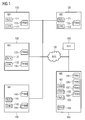
- measuring and monitoring device comprises a base module 100 and a plurality of arranged in the base module 100 modules 110, 120, 130, 140 for control, measuring and / or monitoring functions, which are connected to the base module 100 via a bus system 150 are.
- the control, measuring and monitoring device may be, for example, a gas analyzer.
- the following statements are generally applicable to any modular control, measuring and / or monitoring devices that can be used in an industrial automation system.
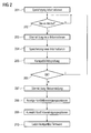
- the flowchart shown in FIG. 1 initially stores information 105-108 (step 201) in a memory unit assigned to the basic module 100 for modules 110, 120, 130, 140 connected to the basic module 100, which contains a module identifier for each module, an indication of a firmware version of the module and include a copy of configuration parameters.
- the configuration parameters stored in the basic module 100 of modules connected to the basic module 100 are continuously updated.
- Originals of the configuration parameters 113, 123, 133, 143 are also stored in memory units of the respective modules 110, 120, 130, 140.
- an automatic transmission of configuration parameters of the module to the replacement module takes place, preferably only after user approval.
- a message is signaled at a user interface 160 connected to the basic module 100, so that a configuration change can be confirmed or a system restart can be initiated with renewed module recognition.
- An affirmative by a user release transmission of configuration parameters offers the advantage that in addition to an automatic transmission and a retention of existing configuration parameters on the replacement module is possible.
- copies of configuration parameters 134, 144 of the basic module are stored in addition to own configuration parameters.
- the originals of the configuration parameters 104 of the basic module are stored in the basic module 100 itself.
- the configuration parameters of the basic module can be changed by restoring the copies stored in the selected modules 130, 140.
- step 202 it is continuously checked whether a new module is connected to the basic module 100 (step 202).
- the new module transmits a registration message to the base module that includes a module identifier and an indication of a firmware version of the new module (step 203).
- the transmitted module identifier and the firmware version of the new module are stored in the basic module 100 (step 204).
- the base module 100 also communicates a collective message to the modules 110, 120, 130, 140 connected to the base module 100, which includes module identifiers stored in the base module 100 and associated information about firmware versions.
- the modules 110, 120, 130, 140 connected to the basic module 100 independently perform a check of compatibility of their own firmware version with the firmware version of other modules connected to the basic module 100 (step 205). Subsequently, within the basis of FIG. 2 In accordance with step 206, the method illustrated in FIG. 2 illustrates a branch as a function of a detected incompatibility. If there are no incompatibilities, a positive acknowledgment message is transmitted to the basic module 100 and, in accordance with step 202, it is checked again whether a new module is connected to the basic module 100.
- the respective module transmits a status message to the basic module 100 (step 207).
- the status message includes the module identifier of a module incompatible due to the firmware version and an indication of incompatible one Module required version version for incompatibility elimination.
- the modules 110, 120, 130, 140 each include a transmitting and receiving unit 111, 121, 131, 141 for the transmission of registration messages and status messages to the basic module 100.
- a respective testing unit 112, 122, 132, 142 for performing the independent Compatibility check provided.
- the basic module 100 comprises a main memory 101 and a processor 102.
- the main memory 101 can load a processor program that can be processed by the processor 102, which comprises at least one code section. When this code section is executed, the method steps described above are initiated when the control program in the basic module 100 expires.
- a transmission and reception unit 103 is provided in the basic module 100 for the transmission of collective messages and for the reception of registration messages and status messages.
- the compatibility check of the firmware version of a testing module with the firmware version of other modules is preferably carried out only for interdependent modules.
- a detected incompatibility by a testing module advantageously a transition of the testing module or a module incompatible with the module to be tested in a defined operating state to be caused.
- the base module 100 provides a variety of conflict resolution options upon detection of incompatibility at the user interface 160 connected to the base module 100.
- a conflict resolution option step 209
- mutually compatible firmware loading is caused by modules affected by the detected incompatibility according to a selected conflict resolution option (step 210).
- the basic module in the present embodiment a prevention of system start of the control, measuring and monitoring device.
- the basic module 100 in addition to the module identifier and for indicating the firmware version for modules connected to the basic module, in each case a connection address of a module is stored on the basic module. In this way, a change of position of modules within the basic module 100 can be detected. This may be of interest, for example, in devices that are integrated in an analysis process, especially if this has an effect on a mechanical structure of a plant.
- parameters of successor firmware are compatible with parameters of previous versions. If new parameters are introduced during a firmware change, they should be appended in a parameter structure at the back. No longer required parameters of a previous version, renamed by adding a pre- or postfix. In this way it is recognizable for developers that such parameters should basically no longer be used, since they are no longer supported, for example, in future versions. If a previous parameter at If a new format is to be obtained for a version change, a new parameter is preferably created and the previous parameter is renamed as described above.
- the modules check, based on the module type and parameter block version identification, whether parameter blocks are compatible with the existing firmware. If a parameter block is newer than specified for the existing firmware, an error message should be signaled at the user interface 160.
Landscapes
- Engineering & Computer Science (AREA)
- Software Systems (AREA)
- Physics & Mathematics (AREA)
- General Engineering & Computer Science (AREA)
- General Physics & Mathematics (AREA)
- Theoretical Computer Science (AREA)
- Automation & Control Theory (AREA)
- Computer Security & Cryptography (AREA)
- Manufacturing & Machinery (AREA)
- Quality & Reliability (AREA)
- Stored Programmes (AREA)
Abstract
Description
In modular aufgebauten Steuerungs-, Meß- oder Analysegeräten für industrielle Automatisierungssysteme werden Module u.a. zu Wartungs- oder Reparaturzwecken durch Ersatzmodule ausgetauscht, oder es werden neue Module zusätzlich zu bereits vorhandenen ergänzt. Dabei ist sicherzustellen, daß Ersatz- oder Ergänzungsmodule kompatibel zu vorhandenen Modulen sind und ihre Parameter korrekt initialisiert werden. Bei konventionellen Steuerungs-, Meß- oder Analysegeräten werden Parametrierungsdaten für angeschlossene Module zur Sicherung üblicherweise manuell auf ein externes Gerät wie einen PC übertragen und dort gespeichert. In Fehlerfällen ist dabei problematisch, daß entweder keine Sicherung von Parametrierungsdaten vorliegt oder diese veraltet sein kann. Infolge dessen kann für ein Ersatzmodul eine aufwendige Neuparametrierung und Initialisierung erforderlich werden. In industriellen Automatisierungssystemen ist dies besonders problematisch, wenn hierdurch kostspielige Anlagenstillstandszeiten beispielsweise in einem Fertigungsautomatisierungsprozeß verursacht werden.In modular control, measuring or analysis devices for industrial automation systems, modules i.a. replaced by replacement modules for maintenance or repair, or new modules are added in addition to existing ones. It must be ensured that replacement or supplementary modules are compatible with existing modules and that their parameters are initialized correctly. In conventional control, measuring or analysis devices, parameterization data for connected modules for backup are usually transmitted manually to an external device such as a PC and stored there. In error cases, it is problematic that either there is no backup of parameterization data or this can be outdated. As a result, for a replacement module, a complex reparameterization and initialization may be required. In industrial automation systems, this is particularly problematic if this causes costly plant downtime, for example, in a factory automation process.
Aus
Der vorliegenden Erfindung liegt die Aufgabe zugrunde, ein effizientes Verfahren zum zuverlässigen Betrieb einer modularen Steuerungs-, Meß- und/oder Überwachungseinrichtung zu schaffen und geeignete Mittel zur Durchführung des Verfahrens anzugeben.The present invention has for its object to provide an efficient method for the reliable operation of a modular control, measuring and / or monitoring device and to provide suitable means for performing the method.
Diese Aufgabe wird erfindungsgemäß durch ein Verfahren mit den in Anspruch 1 angegebenen Merkmalen, eine Steuerungs-, Meß- und/oder Überwachungseinrichtung mit den in Anspruch 11 angegebenen Merkmalen, ein Steuerungs-, Meß- und/oder Überwachungsmodul mit den in Anspruch 12 angegebenen Merkmalen und ein Steuerungsprogramm mit den in Anspruch 13 angegebenen Merkmalen gelöst. Vorteilhafte Weiterbildungen der vorliegenden Erfindung sind in den abhängigen Ansprüchen angegeben.This object is achieved by a method with the features specified in claim 1, a control, measuring and / or monitoring device with the features specified in claim 11, a control, measuring and / or monitoring module with the features specified in claim 12 and a control program having the features specified in claim 13. Advantageous developments of the present invention are specified in the dependent claims.
Entsprechend dem erfindungsgemäßen Verfahren sind in einer Speichereinheit, die einem Grundmodul einer Steuerungs-, Meß- und/oder Überwachungseinrichtung zugeordnet ist, für mit dem Grundmodul verbundene erste Module zumindest jeweils ein Modulidentifikator und eine Angabe über eine Firmwareversion eines ersten Moduls gespeichert. Die Steuerungs-, Meß- und/oder Überwachungseinrichtung kann beispielsweise einem industriellen Automatisierungssystem zur Fertigungs-, Prozeß- oder Gebäudeautomatisierung zugeordnet sein. Ein zweites Modul übermittelt bei Verbindung mit dem Grundmodul eine erste Meldung an das Grundmodul, die einen Modulidentifikator und eine Angabe über eine Firmwareversion des zweiten Moduls umfaßt. Der übermittelte Modulidentifikator und die Angabe der Firmwareversion des zweiten Moduls werden automatisch in der Speichereinheit gespeichert. Das Grundmodul übermittelt eine zweite Meldung an mit dem Grundmodul verbundene Module, die in der Speichereinheit gespeicherte Modulidentifikatoren und zugeordnete Angaben über Firmwareversionen umfaßt. Anhand der zweiten Meldung führen mit dem Grundmodul verbundene Module jeweils eigenständig eine Prüfung einer Kompatibilität ihrer eigenen Firmwareversion mit der Firmwareversion anderer mit dem Grundmodul verbundener Module durch. Bei einer erkannten Inkompatibilität übermittelt ein Modul eine Statusmeldung an das Grundmodul, die zumindest den Modulidentifikator eines aufgrund der Firmwareversion inkompatiblen Moduls und eine Angabe eines für das inkompatible Modul erforderlichen Versionsstandes zur Inkompatibilitätsbeseitigung umfaßt. Auf diese Weise kann durch das Grundmodul eine automatisierte Inkompatibilitätsbeseitigung veranlaßt werden.According to the inventive method are stored in a memory unit which is assigned to a basic module of a control, measuring and / or monitoring device for connected to the base module first modules at least one module identifier and an indication of a firmware version of a first module. The control, measuring and / or monitoring device can be assigned, for example, to an industrial automation system for production, process or building automation. A second module, when connected to the base module, transmits a first message to the base module that includes a module identifier and an indication of a firmware version of the second module. The transmitted module identifier and the firmware version of the second module are automatically displayed in the Memory unit stored. The base module transmits a second message to modules connected to the base module that includes module identifiers stored in the memory unit and associated firmware version information. On the basis of the second message, modules connected to the basic module independently carry out a check for compatibility of their own firmware version with the firmware version of other modules connected to the basic module. Upon a detected incompatibility, a module communicates a status message to the base module that includes at least the module identifier of a module incompatible due to the firmware version and an indication of an incompatibility level required for the incompatible module. In this way, an automated incompatibility elimination can be caused by the basic module.
Vorzugsweise stellt das Grundmodul bei einer erkannten Inkompatibilität an einer Benutzerschnittstelle eine Auswahl an Konfliktbereinigungsoptionen bereit. Auf eine Benutzerauswahl veranlaßt das Grundmodul ein Laden zueinander kompatibler Firmware durch von der erkannten Inkompatibilität betroffene Module entsprechend einer ausgewählten Konfliktbereinigungsoption. Auf diese Weise lassen sich Risiken einer Fehlkonfigurierung bei einem Konfliktbereinigungsversuch minimieren. Entsprechend einer weiteren vorteilhaften Ausgestaltung der vorliegenden Erfindung veranlaßt das Grundmodul bei einer bestehenden Inkompatibilität eine Verhinderung eines Systemstarts der Steuerungs-, Meß- und/oder Überwachungseinrichtung.Preferably, the base module provides a selection of conflict resolution options upon a detected incompatibility on a user interface. Upon user selection, the base module causes a compatible firmware to be loaded by modules affected by the detected incompatibility according to a selected conflict resolution option. In this way, risks of misconfiguration in a conflict resolution attempt can be minimized. According to a further advantageous embodiment of the present invention causes the base module in an existing incompatibility preventing a system start of the control, measuring and / or monitoring device.
Entsprechend einer besonders bevorzugten Weiterbildung der vorliegenden Erfindung werden Konfigurationsparameter von mit dem Grundmodul verbundenen Modulen in der Speichereinheit gespeichert und laufend aktualisiert. Auf diese Weise kann sichergestellt werden, daß im Fall eines Modulfehlers und Austauschs durch ein Ersatzmodul keine Konfigurationsparameter verloren gehen, wodurch etwaige Ausfallzeiten reduziert werden. Bei einem Austausch eines mit dem Grundmodul verbundenen Moduls durch ein Ersatzmodul erfolgt vorzugsweise eine automatische Übertragung von Konfigurationsparametern des Moduls auf das Ersatzmodul. Entsprechend einer weiteren Ausgestaltung der vorliegenden Erfindung erfolgt die Übertragung der Konfigurationsparameter auf das Ersatzmodul erst nach Benutzerfreigabe. Hierdurch wird Bedienpersonal die Möglichkeit eröffnet, eine Übernahme von Konfigurationsparametern bedarfsgerecht zu steuern.According to a particularly preferred development of the present invention, configuration parameters of modules connected to the basic module are stored in the memory unit and continuously updated. This way you can be sure In the case of module failure and replacement module replacement, no configuration parameters will be lost, thereby reducing any downtime. When replacing a module connected to the base module by a replacement module, preferably an automatic transmission of configuration parameters of the module to the replacement module takes place. According to a further embodiment of the present invention, the transmission of the configuration parameters to the replacement module takes place only after user approval. This will allow operators to control the acquisition of configuration parameters as needed.
Die Erfindung wird nachfolgend an einem Ausführungsbeispiel anhand der Zeichnung näher erläutert. Es zeigt
- Figur 1
- eine Strukturdarstellung einer modularen Steuerungs-, Meß- und Überwachungseinrichtung,
- Figur 2
- ein Ablaufdiagramm für ein Verfahren zum Betrieb einer Steuerungs-, Meß- und Überwachungseinrichtung.
- FIG. 1
- a structural representation of a modular control, measuring and monitoring device,
- FIG. 2
- a flowchart for a method for operating a control, measuring and monitoring device.
Die in
Entsprechend dem in
Bei einem Austausch eines mit dem Grundmodul 100 verbundenen Moduls durch ein Ersatzmodul erfolgt eine automatische Übertragung von Konfigurationsparametern des Moduls auf das Ersatzmodul, vorzugsweise erst nach Benutzerfreigabe. Zur Benutzerfreigabe wird eine Meldung an einer mit dem Grundmodul 100 verbundenen Benutzerschnittstelle 160 signalisiert, so daß eine Konfigurationsänderung bestätigt oder ein Systemneuanlauf mit erneuter Modulerkennung veranlaßt werden kann. Eine durch eine Benutzerfreigabe zu bestätigende Übertragung von Konfigurationsparametern bietet als Vorteil, daß neben einer automatischen Übertragung auch eine Beibehaltung von bestehenden Konfigurationsparametern auf dem Ersatzmodul möglich ist.When replacing a module connected to the
In ausgewählten Modulen 130, 140 sind zusätzlich zu eigenen Konfigurationsparametern auch Kopien von Konfigurationsparametern 134, 144 des Grundmoduls gespeichert. Die Originale der Konfigurationsparameter 104 des Grundmoduls sind im Grundgrundmodul 100 selbst gespeichert. Bei einem Austausch des Grundmoduls können die Konfigurationsparameter des Grundmoduls durch Rückgriff auf die in den ausgewählten Modulen 130, 140 gespeicherten Kopien wiederhergestellt werden.In
Darüber hinaus wird fortlaufend überprüft, ob ein neues Modul mit dem Grundmodul 100 verbunden wird (Schritt 202). Wird ein neues Modul mit dem Grundmodul 100 verbunden, übermittelt das neue Modul eine Registrierungsmeldung an das Grundmodul, die einen Modulidentifikator und eine Angabe über eine Firmwareversion des neuen Moduls umfaßt (Schritt 203). Anschließend werden der übermittelte Modulidentifikator und die Angabe der Firmwareversion des neuen Moduls im Grundmodul 100 gespeichert (Schritt 204). Das Grundmodul 100 übermittelt außerdem eine Sammelmeldung an die mit dem Grundmodul 100 verbundene Module 110, 120, 130, 140, die im Grundmodul 100 gespeicherte Modulidentifikatoren und zugeordnete Angaben über Firmwareversionen umfaßt. Anhand dieser Meldung führen die mit dem Grundmodul 100 verbundenen Module 110, 120, 130, 140 jeweils eigenständig eine Prüfung einer Kompatibilität ihrer eigenen Firmwareversion mit der Firmwareversion anderer mit dem Grundmodul 100 verbundener Module durch (Schritt 205). Anschließend erfolgt innerhalb des anhand von
Bei einer durch eines der Module erkannten Inkompatibilität übermittelt das jeweilige Modul eine Statusmeldung an das Grundmodul 100 (Schritt 207). Die Statusmeldung umfaßt den Modulidentifikator eines aufgrund der Firmwareversion inkompatiblen Moduls und eine Angabe eines für das inkompatible Modul erforderlichen Versionsstandes zur Inkompatibilitätsbeseitigung.In case of an incompatibility detected by one of the modules, the respective module transmits a status message to the basic module 100 (step 207). The status message includes the module identifier of a module incompatible due to the firmware version and an indication of incompatible one Module required version version for incompatibility elimination.
Die Module 110, 120, 130, 140 umfassen jeweils eine Sende- und Empfangseinheit 111, 121, 131, 141 zur Übermittlung von Registrierungsmeldungen und Statusmeldungen an das Grundmodul 100. Außerdem ist jeweils eine Prüfeinheit 112, 122, 132, 142 zur Durchführung der eigenständigen Prüfung der Kompatibilität vorgesehen.The
Das Grundmodul 100 umfaßt einen Arbeitsspeicher 101 und einen Prozessor 102. In den Arbeitsspeicher 101 ist ein durch den Prozessor 102 verarbeitbares Steuerungsprogramm ladbar, das zumindest einen Codeabschnitt umfaßt. Bei Ausführung dieses Codeabschnitts werden vorangehend beschriebene Verfahrensschritte veranlaßt, wenn das Steuerungsprogramm im Grundmodul 100 abläuft. Außerdem ist im Grundmodul 100 eine Sende- und Empfangseinheit 103 zur Übermittlung von Sammelmeldungen und zum Empfang von Registrierungsmeldungen und Statusmeldungen vorgesehen.The
Bei der Prüfung der Kompatibilität der Firmwareversion eines prüfenden Moduls mit der Firmwareversion anderer Module wird ermittelt, ob der Versionsstand eines jeweils anderen Moduls mindestens einem durch das prüfende Modul für das jeweils andere Modul geforderten Versionsstand entspricht. Aus Effizienzgründen wird die Prüfung der Kompatibilität der Firmwareversion eines prüfenden Moduls mit der Firmwareversion anderer Module vorzugsweise nur für voneinander abhängige Module durchgeführt. Außerdem sollte bei einer erkannten Inkompatibilität durch ein prüfendes Modul vorteilhafterweise ein Übergang des prüfenden Moduls bzw. eines mit dem prüfenden Modul inkompatiblen Moduls in einen definierten Betriebszustand veranlaßt werden.When verifying the compatibility of the firmware version of a test module with the firmware version of other modules, it is determined whether the version level of any other module is equal to or greater than the level required by the test module for the other module. For efficiency reasons, the compatibility check of the firmware version of a testing module with the firmware version of other modules is preferably carried out only for interdependent modules. In addition, should a detected incompatibility by a testing module advantageously a transition of the testing module or a module incompatible with the module to be tested in a defined operating state to be caused.
Entsprechend Schritt 208 des in
Bei einer bestehenden Inkompatibilität veranlaßt das Grundmodul im vorliegenden Ausführungsbeispiel eine Verhinderung eines Systemstarts der Steuerungs-, Meß- und Überwachungseinrichtung. Zudem wird im Grundmodul 100 zusätzlich zum Modulidentifikator und zur Angabe der Firmwareversion für mit dem Grundmodul verbundene Module jeweils eine Anschlußadresse eines Moduls am Grundmodul gespeichert. Auf diese Weise kann ein Positionswechsel von Modulen innerhalb des Grundmoduls 100 erkannt werden. Dies kann beispielsweise bei Geräten, die in einen Analyseprozeß integriert sind, von Interesse sein, insbesondere wenn dies Auswirkungen auf einen mechanischen Aufbau einer Anlage hat.In an existing incompatibility causes the basic module in the present embodiment, a prevention of system start of the control, measuring and monitoring device. In addition, in the
Grundsätzlich sollte sichergestellt werden, daß Parameter von Nachfolgefirmware kompatibel zu Parametern von Vorgängerversionen sind. Falls bei einer Firmwareänderung neue Parameter eingeführt werden, sollten diese in einer Parameterstruktur hinten angehängt werden. Nicht mehr benötigte Parameter einer Vorgängerversion, durch Ergänzung eines Prä- oder Postfixes umbenannt. Auf diese Weise ist für Entwickler erkennbar, daß derartige Parameter grundsätzlich nicht mehr verwendet werden sollen, da sie beispielsweise in zukünftigen Versionen nicht mehr unterstützt werden. Falls ein bisheriger Parameter bei einem Versionswechsel ein neues Format erhalten soll, wird vorzugsweise ein neuer Parameter angelegt und der bisherige Parameter wie oben beschrieben umbenannt.Basically, it should be ensured that parameters of successor firmware are compatible with parameters of previous versions. If new parameters are introduced during a firmware change, they should be appended in a parameter structure at the back. No longer required parameters of a previous version, renamed by adding a pre- or postfix. In this way it is recognizable for developers that such parameters should basically no longer be used, since they are no longer supported, for example, in future versions. If a previous parameter at If a new format is to be obtained for a version change, a new parameter is preferably created and the previous parameter is renamed as described above.
Die Parameter eines Moduls sind im vorliegenden Ausführungsbeispiel blockweise in einer Struktur organisiert, die zur Identifikation folgende Informationen umfassen:
- Modultyp,
- Parameterblocklänge,
- Parameterblockversionskennung.
- Module type,
- Parameter block length,
- Parameter block version ID.
Beim Hochlauf prüfen die Module anhand von Modultyp und Parameterblockversionskennung, ob Parameterblöcke kompatibel zur vorhandenen Firmware sind. Ist ein Parameterblock neuer als für die vorhandene Firmware spezifiziert, sollte eine Fehlermeldung an der Benutzerschnittstelle 160 signalisiert werden.During startup, the modules check, based on the module type and parameter block version identification, whether parameter blocks are compatible with the existing firmware. If a parameter block is newer than specified for the existing firmware, an error message should be signaled at the
Ist die Parameterblockversionskennung kleiner als für die vorhandene Firmware spezifiziert, sollte eine Warnmeldung an der Benutzerschnittstelle 160 signalisiert werden, da neu hinzugefügte Parameter in diesem Fall mit Standardwerten belegt werden, die anwenderseitig neu eingestellt werden können.If the parameter block version identifier is smaller than specified for the existing firmware, a warning message should be signaled at the
Die Anwendung der vorliegenden Erfindung ist nicht auf das beschriebene Ausführungsbeispiel beschränkt.The application of the present invention is not limited to the described embodiment.
Claims (13)
bei dem bei der Prüfung der Kompatibilität der Firmwareversion eines prüfenden Moduls mit der Firmwareversion anderer Module ermittelt wird, ob der Versionsstand eines jeweils anderen Moduls mindestens einem durch das prüfende Modul für das jeweils andere Modul geforderten Versionsstand entspricht.Method according to claim 1,
Determining the compatibility of the firmware version of a test module with the firmware version of other modules to determine if the version level of any other module is at least equal to a version required by the test module for the other module.
bei dem die Prüfung der Kompatibilität der Firmwareversion eines prüfenden Moduls mit der Firmwareversion anderer Module nur für voneinander abhängige Module durchgeführt wird.Method according to one of claims 1 or 2,
where the compatibility check of the firmware version of a test module with the firmware version of other modules is only done for mutually dependent modules.
bei dem bei einer erkannten Inkompatibilität durch ein prüfendes Modul ein Übergang des prüfenden Moduls und/oder eines mit dem prüfenden Modul inkompatiblen Moduls in einen definierten Betriebszustand veranlaßt wird.Method according to one of claims 1 to 3,
in which, in the event of a detected incompatibility by a testing module, a transition of the testing module and / or a module incompatible with the testing module into a defined operating state is initiated.
bei dem das Grundmodul bei einer erkannten Inkompatibilität an einer Benutzerschnittstelle eine Auswahl an Konfliktbereinigungsoptionen bereitstellt und auf eine Benutzerauswahl ein Laden zueinander kompatibler Firmware durch von der erkannten Inkompatibilität betroffene Module entsprechend einer ausgewählten Konfliktbereinigungsoption veranlaßt.Method according to one of claims 1 to 4,
wherein the base module, upon a recognized incompatibility on a user interface, provides a selection of conflict resolution options and causes a user selection to load compatible firmware by modules affected by the detected incompatibility according to a selected conflict resolution option.
bei dem das Grundmodul bei einer bestehenden Inkompatibilität eine Verhinderung eines Systemstarts der Steuerungs-, Meß- und/oder Überwachungseinrichtung veranlaßt.Method according to one of claims 1 to 5,
in which the basic module, in the case of an existing incompatibility, causes a prevention of a system start of the control, measuring and / or monitoring device.
bei dem in der Speichereinheit zusätzlich zum Modulidentifikator und zur Angabe der Firmwareversion für mit dem Grundmodul verbundene Module jeweils eine Anschlußadresse eines Moduls am Grundmodul gespeichert wird.Method according to one of claims 1 to 6,
in which in each case a connection address of a module is stored on the basic module in the memory unit in addition to the module identifier and for indicating the firmware version for modules connected to the basic module.
bei dem Konfigurationsparameter von mit dem Grundmodul verbundenen Modulen in der Speichereinheit gespeichert und laufend aktualisiert werden.Method according to one of claims 1 to 7,
in the configuration parameter of modules connected to the basic module are stored in the memory unit and updated continuously.
bei dem bei einem Austausch eines mit dem Grundmodul verbundenen Moduls durch ein Ersatzmodul eine automatische Übertragung von Konfigurationsparametern des Moduls auf das Ersatzmodul erfolgt.Method according to claim 8,
in which, when replacing a module connected to the base module by a replacement module, an automatic transmission of configuration parameters of the module to the replacement module takes place.
bei dem die Übertragung der Konfigurationsparameter auf das Ersatzmodul erst nach Benutzerfreigabe erfolgt.Method according to claim 9,
in which the transmission of the configuration parameters to the replacement module takes place only after user approval.
Priority Applications (1)
| Application Number | Priority Date | Filing Date | Title |
|---|---|---|---|
| EP09004523A EP2237123A1 (en) | 2009-03-30 | 2009-03-30 | Method, apparatus and computer program for local compatibility-check between components in an automation system |
Applications Claiming Priority (1)
| Application Number | Priority Date | Filing Date | Title |
|---|---|---|---|
| EP09004523A EP2237123A1 (en) | 2009-03-30 | 2009-03-30 | Method, apparatus and computer program for local compatibility-check between components in an automation system |
Publications (1)
| Publication Number | Publication Date |
|---|---|
| EP2237123A1 true EP2237123A1 (en) | 2010-10-06 |
Family
ID=40910013
Family Applications (1)
| Application Number | Title | Priority Date | Filing Date |
|---|---|---|---|
| EP09004523A Withdrawn EP2237123A1 (en) | 2009-03-30 | 2009-03-30 | Method, apparatus and computer program for local compatibility-check between components in an automation system |
Country Status (1)
| Country | Link |
|---|---|
| EP (1) | EP2237123A1 (en) |
Cited By (10)
| Publication number | Priority date | Publication date | Assignee | Title |
|---|---|---|---|---|
| WO2012089429A1 (en) * | 2010-12-28 | 2012-07-05 | Endress+Hauser Flowtec Ag | Field device having long-term firmware compatibility |
| EP2541397A1 (en) * | 2011-06-30 | 2013-01-02 | Siemens Aktiengesellschaft | Method for compatibility checking when installing a software component |
| EP2811173A1 (en) | 2013-06-04 | 2014-12-10 | Danfoss Power Solutions Aps | A hydraulic system and a method for operating a hydraulic system |
| WO2016095993A1 (en) * | 2014-12-17 | 2016-06-23 | Siemens Aktiengesellschaft | Checking a functional module of an automation system |
| EP3128383A1 (en) * | 2015-08-03 | 2017-02-08 | Schneider Electric Industries SAS | Field device |
| DE102016204395A1 (en) * | 2016-03-16 | 2017-09-21 | Siemens Schweiz Ag | Tool-free device replacement of bus devices |
| WO2020064443A1 (en) * | 2018-09-25 | 2020-04-02 | Innogy Se | Firmware update by central control module of a charging station |
| EP3671379A1 (en) * | 2018-12-19 | 2020-06-24 | Francotyp-Postalia GmbH | Authentication system and authentication method for performing a work process on an object |
| WO2021008893A1 (en) * | 2019-07-12 | 2021-01-21 | Turck Holding Gmbh | Field device |
| EP3839670A1 (en) * | 2019-12-18 | 2021-06-23 | Eppendorf AG | Method for controlling functional elements and device for use in bioprocessing technology and / or medical technology |
Citations (3)
| Publication number | Priority date | Publication date | Assignee | Title |
|---|---|---|---|---|
| EP0498130A2 (en) | 1991-02-08 | 1992-08-12 | International Business Machines Corporation | Apparatus and method for verifying compatibility of system components |
| WO2005047992A2 (en) * | 2003-11-13 | 2005-05-26 | Siemens Aktiengesellschaft | Automation system with intercommunicating components |
| WO2005106605A1 (en) * | 2004-04-01 | 2005-11-10 | Bayerische Motoren Werke Aktiengesellschaft | Method for identifying incompatibilities in a bus system comprising several control devices |
-
2009
- 2009-03-30 EP EP09004523A patent/EP2237123A1/en not_active Withdrawn
Patent Citations (3)
| Publication number | Priority date | Publication date | Assignee | Title |
|---|---|---|---|---|
| EP0498130A2 (en) | 1991-02-08 | 1992-08-12 | International Business Machines Corporation | Apparatus and method for verifying compatibility of system components |
| WO2005047992A2 (en) * | 2003-11-13 | 2005-05-26 | Siemens Aktiengesellschaft | Automation system with intercommunicating components |
| WO2005106605A1 (en) * | 2004-04-01 | 2005-11-10 | Bayerische Motoren Werke Aktiengesellschaft | Method for identifying incompatibilities in a bus system comprising several control devices |
Cited By (19)
| Publication number | Priority date | Publication date | Assignee | Title |
|---|---|---|---|---|
| WO2012089429A1 (en) * | 2010-12-28 | 2012-07-05 | Endress+Hauser Flowtec Ag | Field device having long-term firmware compatibility |
| CN103282843A (en) * | 2010-12-28 | 2013-09-04 | 恩德斯+豪斯流量技术股份有限公司 | Field device having long-erm firmware compatibility |
| EP2541397A1 (en) * | 2011-06-30 | 2013-01-02 | Siemens Aktiengesellschaft | Method for compatibility checking when installing a software component |
| EP2811173A1 (en) | 2013-06-04 | 2014-12-10 | Danfoss Power Solutions Aps | A hydraulic system and a method for operating a hydraulic system |
| US20170351238A1 (en) * | 2014-12-17 | 2017-12-07 | Siemens Aktiengesellschaft | Checking a functional module of an automation installation |
| US10955804B2 (en) * | 2014-12-17 | 2021-03-23 | Siemens Aktiengesellchaft | Checking a functional module of an automation installation |
| CN107003648A (en) * | 2014-12-17 | 2017-08-01 | 西门子公司 | The inspection of the functional module of automation equipment |
| CN107003648B (en) * | 2014-12-17 | 2019-06-11 | 西门子公司 | The method of inspection and project planning system of the functional module of automation equipment |
| WO2016095993A1 (en) * | 2014-12-17 | 2016-06-23 | Siemens Aktiengesellschaft | Checking a functional module of an automation system |
| EP3128383A1 (en) * | 2015-08-03 | 2017-02-08 | Schneider Electric Industries SAS | Field device |
| DE102016204395A1 (en) * | 2016-03-16 | 2017-09-21 | Siemens Schweiz Ag | Tool-free device replacement of bus devices |
| DE102016204395B4 (en) | 2016-03-16 | 2024-02-08 | Siemens Schweiz Ag | Tool-free device replacement of bus devices |
| WO2020064443A1 (en) * | 2018-09-25 | 2020-04-02 | Innogy Se | Firmware update by central control module of a charging station |
| EP3671379A1 (en) * | 2018-12-19 | 2020-06-24 | Francotyp-Postalia GmbH | Authentication system and authentication method for performing a work process on an object |
| US11334050B2 (en) | 2018-12-19 | 2022-05-17 | Francotyp-Postalia Gmbh | Authentication system and authentication method for executing a work process on an object |
| WO2021008893A1 (en) * | 2019-07-12 | 2021-01-21 | Turck Holding Gmbh | Field device |
| WO2021008894A1 (en) * | 2019-07-12 | 2021-01-21 | Turck Holding Gmbh | Field device |
| EP3839670A1 (en) * | 2019-12-18 | 2021-06-23 | Eppendorf AG | Method for controlling functional elements and device for use in bioprocessing technology and / or medical technology |
| WO2021122333A1 (en) * | 2019-12-18 | 2021-06-24 | Eppendorf Ag | Method for controlling functional elements and device for use in bioprocess engineering and/or medical technology |
Similar Documents
| Publication | Publication Date | Title |
|---|---|---|
| EP2237123A1 (en) | Method, apparatus and computer program for local compatibility-check between components in an automation system | |
| EP3017371B1 (en) | Method for error monitoring, control and data transmission installation and control device | |
| DE102007026678A1 (en) | Method for exchanging a defective field device for a new field device in a system communicating via a digital field bus, in particular an automation system | |
| WO2005054965A1 (en) | Method for the supplying and installation of device-specific functionalities and/or data for the field devices of a distributed system | |
| WO2005033934A2 (en) | Flexible software update for automation systems via internet | |
| EP2062105A1 (en) | System and method for functionalization in line with demand, for control and regulatory devices | |
| DE102012102506A1 (en) | Method for diagnosing e.g. fully automatic coffee machine using smartphone, involves transferring apparatus data and/or error code data of automation system to smartphone, and displaying transferred data on display device of smartphone | |
| DE102006005365A1 (en) | Updating method for firmware of field devices e.g. measuring devices, involves connecting field devices to control unit by common data bus, where firmware is transmitted between all connected field devices by connecting one field device | |
| EP3001310B1 (en) | Method and apparatus for updating firmware for components of an industrial automation system | |
| EP1903436A2 (en) | Computer system and method for updating program code | |
| EP1710647A2 (en) | Integration of field devices in an automation system | |
| WO2015150164A1 (en) | Method for automatic processing of a number of protocol files of an automation system | |
| DE102006035890A1 (en) | System and method for automatically installing and maintaining hardware and software in a distributed computer system | |
| DE102004062432A1 (en) | System and method for automatically creating, installing, and configuring enhancements to the functionalities in the distributed network nodes | |
| EP3353650A1 (en) | System and method for distributing and/or updating software in interconnected control devices of a vehicle | |
| WO2011000367A1 (en) | Method and device for the simplified error processing in a machine tool | |
| DE102010038458A1 (en) | System for operating field devices utilized for acquisition and/or influence of process sensors in process plant in automatic control engineering, has field devices operated by utilization of device drivers that run below computing units | |
| EP2483775A1 (en) | Method and arrangement for installing and configuring a computer system | |
| EP3361341A1 (en) | Method for monitoring the conditions of the devices of an automation system and operator system | |
| EP2399176A1 (en) | Method and system for engineering an automation of at least part of a technical installation | |
| WO2005047992A2 (en) | Automation system with intercommunicating components | |
| EP3056955A1 (en) | Planning and engineering method, software tool and system for a processing assembly | |
| DE102018204734A1 (en) | Security instrumented control apparatus and method, and security instrumented system | |
| DE19927985B4 (en) | Communication device, method for physically and logically installing a packet in the communication device and storage medium | |
| EP2109020B1 (en) | Automation system and method for diagnosis, customisation and optimisation of automation device |
Legal Events
| Date | Code | Title | Description |
|---|---|---|---|
| PUAI | Public reference made under article 153(3) epc to a published international application that has entered the european phase |
Free format text: ORIGINAL CODE: 0009012 |
|
| AK | Designated contracting states |
Kind code of ref document: A1 Designated state(s): AT BE BG CH CY CZ DE DK EE ES FI FR GB GR HR HU IE IS IT LI LT LU LV MC MK MT NL NO PL PT RO SE SI SK TR |
|
| AX | Request for extension of the european patent |
Extension state: AL BA RS |
|
| AKY | No designation fees paid | ||
| REG | Reference to a national code |
Ref country code: DE Ref legal event code: R108 Effective date: 20110526 |
|
| STAA | Information on the status of an ep patent application or granted ep patent |
Free format text: STATUS: THE APPLICATION IS DEEMED TO BE WITHDRAWN |
|
| 18D | Application deemed to be withdrawn |
Effective date: 20110407 |