EP2179317B1 - A mini-scope for multi-directional imaging - Google Patents
A mini-scope for multi-directional imaging Download PDFInfo
- Publication number
- EP2179317B1 EP2179317B1 EP08770221.3A EP08770221A EP2179317B1 EP 2179317 B1 EP2179317 B1 EP 2179317B1 EP 08770221 A EP08770221 A EP 08770221A EP 2179317 B1 EP2179317 B1 EP 2179317B1
- Authority
- EP
- European Patent Office
- Prior art keywords
- optical energy
- mini
- optical
- scope
- selective
- Prior art date
- Legal status (The legal status is an assumption and is not a legal conclusion. Google has not performed a legal analysis and makes no representation as to the accuracy of the status listed.)
- Active
Links
- 238000003384 imaging method Methods 0.000 title claims description 45
- 230000003287 optical effect Effects 0.000 claims description 131
- 238000005286 illumination Methods 0.000 claims description 29
- 230000004044 response Effects 0.000 claims description 16
- 239000004020 conductor Substances 0.000 claims description 14
- 230000010287 polarization Effects 0.000 claims description 14
- 238000012545 processing Methods 0.000 claims description 12
- 238000001454 recorded image Methods 0.000 claims description 10
- 238000000034 method Methods 0.000 claims description 9
- 239000007787 solid Substances 0.000 claims description 7
- 239000013307 optical fiber Substances 0.000 claims description 5
- 238000004891 communication Methods 0.000 claims description 3
- 238000000060 site-specific infrared dichroism spectroscopy Methods 0.000 description 17
- 230000003319 supportive effect Effects 0.000 description 7
- 230000006870 function Effects 0.000 description 4
- 239000000463 material Substances 0.000 description 3
- 239000004065 semiconductor Substances 0.000 description 2
- 229910000530 Gallium indium arsenide Inorganic materials 0.000 description 1
- 239000000919 ceramic Substances 0.000 description 1
- 238000006243 chemical reaction Methods 0.000 description 1
- 230000000295 complement effect Effects 0.000 description 1
- 150000001875 compounds Chemical class 0.000 description 1
- 238000013461 design Methods 0.000 description 1
- 238000009472 formulation Methods 0.000 description 1
- 239000011521 glass Substances 0.000 description 1
- 238000002347 injection Methods 0.000 description 1
- 239000007924 injection Substances 0.000 description 1
- 238000005259 measurement Methods 0.000 description 1
- 229910044991 metal oxide Inorganic materials 0.000 description 1
- 150000004706 metal oxides Chemical class 0.000 description 1
- 239000000203 mixture Substances 0.000 description 1
- 238000012986 modification Methods 0.000 description 1
- 230000004048 modification Effects 0.000 description 1
- 239000004033 plastic Substances 0.000 description 1
- 229920003023 plastic Polymers 0.000 description 1
- 230000008569 process Effects 0.000 description 1
- 230000001902 propagating effect Effects 0.000 description 1
- 238000001228 spectrum Methods 0.000 description 1
Images

Classifications
-
- G—PHYSICS
- G02—OPTICS
- G02B—OPTICAL ELEMENTS, SYSTEMS OR APPARATUS
- G02B23/00—Telescopes, e.g. binoculars; Periscopes; Instruments for viewing the inside of hollow bodies; Viewfinders; Optical aiming or sighting devices
- G02B23/24—Instruments or systems for viewing the inside of hollow bodies, e.g. fibrescopes
- G02B23/2407—Optical details
- G02B23/2423—Optical details of the distal end
-
- A—HUMAN NECESSITIES
- A61—MEDICAL OR VETERINARY SCIENCE; HYGIENE
- A61B—DIAGNOSIS; SURGERY; IDENTIFICATION
- A61B1/00—Instruments for performing medical examinations of the interior of cavities or tubes of the body by visual or photographical inspection, e.g. endoscopes; Illuminating arrangements therefor
- A61B1/00163—Optical arrangements
- A61B1/00174—Optical arrangements characterised by the viewing angles
- A61B1/00181—Optical arrangements characterised by the viewing angles for multiple fixed viewing angles
-
- A—HUMAN NECESSITIES
- A61—MEDICAL OR VETERINARY SCIENCE; HYGIENE
- A61B—DIAGNOSIS; SURGERY; IDENTIFICATION
- A61B1/00—Instruments for performing medical examinations of the interior of cavities or tubes of the body by visual or photographical inspection, e.g. endoscopes; Illuminating arrangements therefor
- A61B1/00163—Optical arrangements
- A61B1/00174—Optical arrangements characterised by the viewing angles
- A61B1/00183—Optical arrangements characterised by the viewing angles for variable viewing angles
-
- A—HUMAN NECESSITIES
- A61—MEDICAL OR VETERINARY SCIENCE; HYGIENE
- A61B—DIAGNOSIS; SURGERY; IDENTIFICATION
- A61B1/00—Instruments for performing medical examinations of the interior of cavities or tubes of the body by visual or photographical inspection, e.g. endoscopes; Illuminating arrangements therefor
- A61B1/04—Instruments for performing medical examinations of the interior of cavities or tubes of the body by visual or photographical inspection, e.g. endoscopes; Illuminating arrangements therefor combined with photographic or television appliances
- A61B1/05—Instruments for performing medical examinations of the interior of cavities or tubes of the body by visual or photographical inspection, e.g. endoscopes; Illuminating arrangements therefor combined with photographic or television appliances characterised by the image sensor, e.g. camera, being in the distal end portion
-
- G—PHYSICS
- G02—OPTICS
- G02B—OPTICAL ELEMENTS, SYSTEMS OR APPARATUS
- G02B23/00—Telescopes, e.g. binoculars; Periscopes; Instruments for viewing the inside of hollow bodies; Viewfinders; Optical aiming or sighting devices
- G02B23/24—Instruments or systems for viewing the inside of hollow bodies, e.g. fibrescopes
- G02B23/2476—Non-optical details, e.g. housings, mountings, supports
- G02B23/2484—Arrangements in relation to a camera or imaging device
-
- G—PHYSICS
- G02—OPTICS
- G02B—OPTICAL ELEMENTS, SYSTEMS OR APPARATUS
- G02B27/00—Optical systems or apparatus not provided for by any of the groups G02B1/00 - G02B26/00, G02B30/00
- G02B27/10—Beam splitting or combining systems
- G02B27/14—Beam splitting or combining systems operating by reflection only
- G02B27/141—Beam splitting or combining systems operating by reflection only using dichroic mirrors
-
- G—PHYSICS
- G02—OPTICS
- G02B—OPTICAL ELEMENTS, SYSTEMS OR APPARATUS
- G02B27/00—Optical systems or apparatus not provided for by any of the groups G02B1/00 - G02B26/00, G02B30/00
- G02B27/28—Optical systems or apparatus not provided for by any of the groups G02B1/00 - G02B26/00, G02B30/00 for polarising
- G02B27/283—Optical systems or apparatus not provided for by any of the groups G02B1/00 - G02B26/00, G02B30/00 for polarising used for beam splitting or combining
-
- H—ELECTRICITY
- H04—ELECTRIC COMMUNICATION TECHNIQUE
- H04N—PICTORIAL COMMUNICATION, e.g. TELEVISION
- H04N23/00—Cameras or camera modules comprising electronic image sensors; Control thereof
- H04N23/50—Constructional details
- H04N23/555—Constructional details for picking-up images in sites, inaccessible due to their dimensions or hazardous conditions, e.g. endoscopes or borescopes
Landscapes
- Health & Medical Sciences (AREA)
- Life Sciences & Earth Sciences (AREA)
- Physics & Mathematics (AREA)
- Surgery (AREA)
- Optics & Photonics (AREA)
- Engineering & Computer Science (AREA)
- Medical Informatics (AREA)
- General Health & Medical Sciences (AREA)
- Pathology (AREA)
- Nuclear Medicine, Radiotherapy & Molecular Imaging (AREA)
- Biomedical Technology (AREA)
- Heart & Thoracic Surgery (AREA)
- Biophysics (AREA)
- Molecular Biology (AREA)
- Animal Behavior & Ethology (AREA)
- Radiology & Medical Imaging (AREA)
- Public Health (AREA)
- Veterinary Medicine (AREA)
- Astronomy & Astrophysics (AREA)
- General Physics & Mathematics (AREA)
- Multimedia (AREA)
- Signal Processing (AREA)
- Endoscopes (AREA)
- Studio Devices (AREA)
- Instruments For Viewing The Inside Of Hollow Bodies (AREA)
Description
-
JP2001 314365A -
JP60104470 - The features of the preambles of claim 1 and 11 are known from
JP2001 314365A - The present invention provides a mini-scope for multi-directional imaging according to claim 1. The present invention also provides a method for multi-directional imaging according to claim 11.
- The scope of the present invention is defined by the claims. Any information provided herein that does not fall within the claims is presented for information purposes only.
-
-
FIG. 1 is a side view of a mini -scope with a single mirror; -
FIG. 2a-2b is a side view of another mini -scope with a single mirror; -
FIG. 3 is a side view of a mini-scope with a single mirror emitting and imaging multiple beams of optical energy; -
FIG. 4 is a side view of a mini-scope having a prism member; -
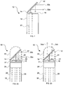
FIG. 5 is a side view of a mini-scope having a plurality of selective mirrors, in accordance with the present invention; -
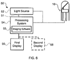
FIG. 6 is a process flow chart illustrating one embodiment of the present invention with multiple displays; and -
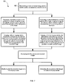
FIG. 7 is a flow chart of a method for multidirectional imaging, in accordance with another embodiment of the present invention. - Reference will now be made to the exemplary embodiments illustrated, and specific language will be used herein to describe the same. It will nevertheless be understood that no limitation of the scope of the invention is thereby intended.
- The following detailed description of exemplary embodiments of the invention makes reference to the accompanying drawings, which form a part hereof, and in which are shown, by way of illustration, exemplary embodiments in which the invention may be practiced. While these exemplary embodiments are described in sufficient detail to enable those skilled in the art to practice the invention, it should be understood that other embodiments may be realized and that various changes to the invention may be made without departing from the spirit and scope of the present invention. Thus, the following more detailed description of the embodiments of the present invention, as represented in
FIGS. 1 through 7 , is not intended to limit the scope of the invention, as claimed, but is presented for purposes of illustration and to sufficiently enable one skilled in the art to practice the invention. Accordingly, the scope of the present invention is to be defined solely by the appended claims. - The following detailed description and exemplary embodiments of the invention will be best understood by referencing the accompanying drawings, wherein the elements and features of the invention are designated by numerals throughout.
- In describing and claiming the present invention, the following terminology will be used:
- The singular forms "a," "an," and "the" include plural referents unless the context clearly dictates otherwise. Thus, for example, reference to "a beam of optical energy" includes reference to one or more of such beams, and reference to "an emitter" includes reference to one or more of such emitters.
- As used herein, "mini-scope" refers to a miniature optical instrument for examining the inner parts of the body as well as for other optical applications.
- As used herein, "SSID," Solid State Imaging Device, refers to a camera or imaging device having a size approximately equal to or less than the diameter of a bundle of optical fibers. SSIDs include, for example, charge-injection devices (CID), charge-coupled devices (CCD), complementary metal oxide semiconductor (CMOS) devices, and other miniature-sized imaging devices, including those made from compound semiconductors such as InGaAs, capable of imaging reflected illumination of visible and/or non-visible light.
- As used herein, "selective mirror" refers to a surface, having selective reflection properties, based on various characteristics of the incident optical energy. These characteristics can include, for example: wavelength, polarization, intensity, direction, angle, frequency, and other like characteristics. The surface can be planar or nonplanar as suits a particular configuration.
- As used herein, a plurality of items, structural elements, compositional elements, and/or materials may be presented in a common list for convenience. However, these lists should be construed as though each member of the list is individually identified as a separate and unique member. Thus, no individual member of such a list should be construed as a de facto equivalent of any other member of the same list solely based on their presentation in a common group without indications to the contrary.
- Concentrations, amounts, and other numerical data may be expressed or presented herein in a range format. It is to be understood that such a range format is used merely for convenience and brevity and thus should be interpreted flexibly to include not only the numerical values explicitly recited as the limits of the range, but also to include all the individual numerical values or sub-ranges encompassed within that range as if each numerical value and sub-range were explicitly recited.
- As an illustration, a numerical range of "about 1 micrometer to about 5 micrometers" should be interpreted to include not only the explicitly recited values of about 1 micrometer to about 5 micrometers, but also include individual values and sub-ranges within the indicated range. Thus, included in this numerical range are individual values such as 2, 3, and 4 and sub-ranges such as from 1-3, from 2-4, and from 3-5, etc. This same principle applies to ranges reciting only one numerical value and should apply regardless of the breadth of the range or the characteristics being described.
- As used herein, the term "about" means that dimensions, sizes, formulations, parameters, shapes and other quantities and characteristics are not and need not be exact, but may be approximated and/or larger or smaller, as desired, reflecting tolerances, conversion factors, rounding off, measurement error, and the like, and other factors known to those of skill in the art.
- Method steps, as described herein, can be performed without regard to order, unless specifically stated.
- As illustrated in
FIG. 1 , a mini-scope 10, i includes a means for optically conducting a beam of optical energy. This means for optically conducting can include an elongatedmini-scope body 18 having a flexibleoptical conductor 20, a single optical fiber having a jacket, and the like. The flexible optical conductor can be a flexible optical fiber having a substantially small diameter and being configured to transmit optical energy from one end of the mini-scope 10 to an opposite end. The elongated mini-scope body has, for example, a distal end and a proximal end, and a length of approximately 0.1 m to 3 m, with 0.5 m being an exemplary length, and a diameter of approximately 0.5 mm to 5 mm, with 1 mm being an exemplary diameter. In another aspect, a mini-scope 10, includes a source of optical energy (no shown) disposed on a distal end of the mini-scope 10 for generating a beam of optical energy at the distal end of the mini-scope 10. - This elongated mini-scope body is configured to be inserted into or in contact with a patient or device. The mini-scope can further include a means for emitting a beam of optical energy, such as an
emissions aperture 14, an emissions aperture with a lens, or the like. An emissions aperture can be disposed on the distal end of the elongated mini-scope body for emitting the beam of optical energy propagating through the flexible optical conductor. A means for selectively directing a beam of optical energy can be positioned above the emissions aperture to selectively pass and reflect the beam ofoptical energy 32a based on the optical characteristics of the beam, as described in greater detail below. A means for imaging can also be disposed on the distal end of the elongated mini-scope body. This means for imaging can include aSSID 16, such as a mini charge coupled device (CCD) camera, a mini CMOS camera, or another optical energy detector designed to operate at other wavelengths. The means for imaging can image the illumination reflected by an external object in response to the beam ofoptical energy 32b, wherein the illumination is directed to pass through or reflect from the selective mirror to the means for imaging. - A means for selectively directing the beam of optical energy can selectively direct a beam or multiple beams of optical energy based on various optical characteristics of the beam. This means for selectively directing can include a
selective mirror 12. For example, the selective mirror can be a dichroic mirror, a polarization dependant beam splitting plate, a polarization dependant beam splitting cube, a prism, a diffraction grating, or other optical devices that can be configured to selectively pass and reflect a beam or portion of a beam of optical energy based on the properties of the optical energy. In this way, the mini-scope 10 can provide both a forward and a lateral image to a user, without the need for turning, rotating, or redirecting the scope head and without substantially increasing the size of the scope. - The
selective mirror 12 can be a dichroic mirror or a mirror which reflects or passes a beam of optical energy based on the frequency characteristics of the beam of optical energy. Dichroic mirrors can be designed to reflect a specific wavelength region of optical energy. For example, a dichroic mirror can be designed to reflect blue light (e.g., light with an optical wavelength of about 440-550 nm), but pass red light (e.g., light with an optical wavelength of about 625-740 nm). As another example, a filter can be designed to reflect all light having a wavelength of about 450 ± 10 nm, thus reflecting most blue light, while passing light with an optical frequency outside of this range. Similarly, a dichroic mirror can be designed to pass and reflect other frequency regions, such as red light, or all near ultraviolet wavelength of about 380-200 nm. - The
selective mirror 12 can be a polarizing beam splitter cube or other optical element configured to pass or reflect a beam of optical energy based on the polarization characteristics of the beam. Typically, polarization beam splitter plates are designed to separate optical energy into the P- and S- components by passing one component and reflecting the other. This type of selective mirror can pass or reflect a spectrum of light frequencies, given constant P- or S- polarization. - The width of the selective mirror can be approximately the diameter of the elongated mini-scope body, and the length can vary according to the desired angular orientation of the mirror. This selective mirror can have a variety of shapes including an ellipse, a circle, a square, a rectangle, and the like. The selective mirror can be positioned at a fixed or movable angle. For example, this angle can be a 45 degree, 15 degree angle, facing in the reverse direction, or any other angular orientations relative to the plane of the
supportive end structure 28, according to the design, usage, and type of the selective mirror. - As illustrated in
FIG. 2a and 2b for information purposes only, a mini-scope 10, similar to that ofFIG. 1 , further includes aSSID 16, such as a charged coupled device (CCD) camera, having a gradient refractive index (GRIN) lens
22. The SSID is configured to transmit recorded images to a processing system (not shown) via anelectrical connection 26, disposed within the elongatedmini-scope body 18. In another aspect, the images could be sent via a wireless connection to a processing system. The elongated mini-scope body can further include asupportive end structure 28, disposed at its distal end. This supportive end structure can position theemissions aperture 14 and theSSID 16 in a forward direction. This structure can further be coupled to amirror supporting structure 24, which holds theselective mirror 12 in position. The mirror supporting structure can be configured to support and control the structure in a fixed or movable position, according to a variety of suitable structural configurations and embodiments. - The mini-scope 10 can include a rotating device (not shown) for rotating the
selective mirror 12. The rotating device can be coupled to the supportive end structure and be configured to both support, rotate and/or pivot the selective mirror, theemissions aperture 14, and/or theSSID 16 about the center axis of the elongatedmini-scope body 18. The rotating device can also rotate the supportive end structure and/or the selective mirror in other directions, as desired. Alternatively, thesupportive end structure 28 andmirror supporting structure 24 can include rotational means. For example, a mirror supporting structure that serves as a rotating device can rotate the mirror so as to increase or decrease the direction of reflection. This mirror supporting structure can be made of a piezoelectric material that is configured to rotate the mirror in response to a predefined electrical condition. The rotating device can also rotate via a variety of other rotational means, including a mechanical device, electromechanical device, electromagnetic device, or other suitable device. Power for this device can be supplied through theelectrical connection 26, or through a similar connection. - The mini-scope can also include a
transparent shield 30, for protecting the patient and mini-scope elements. The shield may be coupled to thesupportive end structure 28 and can be fabricated from various materials such as plastics, glass, ceramics, etc. - As illustrated in
FIG. 2a , a first beam ofoptical energy 32a can be transmitted down the flexibleoptical conductor 20 and emitted towards theselective mirror 12, via theemissions aperture 14. Upon incidence with the selective mirror, the first beam can be reflected in a lateral direction, based on the optical characteristics of the first beam. According to one embodiment of the invention, the selective mirror can be a dichroic mirror, as described above. The dichroic mirror can be positioned at a 45 degree angle relative to the emissions apertures and can be configured to reflect all light having a wavelength of approximately 450 ± 10 nm (blue light). By way of example, thefirst beam 32a has a wavelength of approximately 450 nm, the beam can be reflected by the dichroic mirror in a lateral direction, based on the optical characteristics of the first beam, as shown. Theillumination 32b reflected by an external object (not shown) in a reverse-lateral direction, in response to the first beam ofoptical energy 32a, can also be directed by the selective mirror to the SSID. The external object is subsequently imaged by the SSID. - Alternatively, as illustrated in
FIG. 2b , if a second beam ofoptical energy 34a, having a wavelength outside of the range 450 ± 10 nm (e.g., approximately 650 nm), is transmitted down the flexibleoptical conductor 20 towards the same dichroic mirror, the second beam can be passed through the dichroic mirror in the forward direction based on the frequency properties of the second beam. Theillumination 34b reflected by an external object (not shown) in a reverse direction, in response to the beam ofoptical energy 34a, can also be reflected by the selective mirror to the SSID, The external object is then imaged by the camera or other means for imaging. - Referring now to
FIG. 3 , a first beam ofoptical energy 32a and a second beam ofoptical energy 34a can be simultaneously transmitted down a flexibleoptical conductor 20, wherein the first and second beams form first and second portions of a single beam of optical energy. In this manner, a first portion of the beam of optical energy can be passed through the selective mirror in a forward direction, while a second portion of the beam of optical energy can be concurrently reflected in a lateral direction. Similarly, the illumination reflected by an external object in a reverse direction, in response to the first portion of the beam, can be passed through the selective mirror to theimaging device 16 to produce a first recorded image. Whereas, the illumination reflected by an external object in a reverse-lateral direction, in response to the second portion of the beam of optical energy can be reflected by the selective mirror to the imaging device, to concurrently produce a second recorded image. - The
selective mirror 12 ofFIG. 2a and 2b can be a polarizing beam splitter plate. The flexibleoptical conductor 20 can be a polarization maintaining optical fiber to maintain the polarization of a transmitted
beam of optical energy. The polarizing beam splitter plate can function similarly to that of the dichroic mirror described above, passing P-polarized beams of optical energy and reflecting S-polarized beams of optical energy, or vice a versa, according to the type and orientation of the polarizing beam splitter. In one aspect of the invention, the function of the polarization beam splitter plate will differ from the function of the dichroic mirror in that the polarization beam splitter will primarily direct illumination reflected by an external object in response to the first or second beam of optical energy that is S-polarized or P-polarized, respectively. In the case that illumination reflected by an external object changes polarization, the polarization beam plate will mostly misdirect this illumination away from the means for imaging orSSID 16. - To decrease the loss of the reflected illumination that has changed polarity, the
selective mirror 12 can further include a non-selective portion, such as a halfsilvered mirror portion 38, as shown inFIG. 3 . The half silvered mirrors reflect half of the incident light and transmit the other half so half of the illuminating light is incident on the SSID array. - The means for selectively directing a beam of optical energy can be a
prism 41, as illustrated inFIG. 4 . The beam of optical energy can include multiple portions, such as frequency portions, including afirst beam portion 32a andsecond beam portion 34a. The prism can selectively direct the beam portions, based on their respective optical characteristics. The reflected illumination of the first and second beam portions (32b and 34b respectively) can be further selectively directed by the prism to theSSID 16 for imaging to produce a recorded image. The recorded image can later be filtered and processed in order to separate the reflected illumination beam portions for display, as will be described below. - As illustrated in
FIG. 5 , in the preferred embodiment, the mini-scope 10 includes a plurality of selective mirrors. By using a plurality of mirrors, the mini-scope can be configured to image multiple directions without the need for rotating the mini-scope device. Two or more cameras can be used according to the selective qualities and ranges of the selective mirrors. Each of the selective mirrors can be configured to selectively pass or reflect the beam of optical energy, based on optical characteristics of the beam. The mini-scope 10 can include a firstselective mirror 12 and a secondselective mirror 12a. This second selective mirror can have a different directional orientation to reflect a beam of optical energy in a second direction, based on the optical characteristics of the beam. Themirror supporting structure 24 can extend from the first selective mirror to the secondselective mirror 12a to control both the positioning and directional orientation of the selective mirrors. Alternatively, a second mirror supporting structure can be included. - According to one embodiment of the present invention, the first and second
selective mirrors selective mirror 12 is configured to reflect optical energy having a wavelength of approximately 450 ± 10 nm, while the second selective mirror is configured to reflect optical energy having a wavelength of approximately 550 ± 10 nm. In order to obtain multi-directional images, a first beam ofoptical energy 32a, having a wavelength of 450 nm, can be transmitted down the flexible optical conductor. This first beam can be reflected by the first selective mirror, illuminating objects in the lateral direction. Simultaneously or alternatively, a second beam ofoptical energy 34a, having a wavelength of 550 nm can be transmitted down the flexible optical conductor. This second beam can pass through the first selective mirror and be reflected off the second selective mirror, illuminating objects in a reverse-lateral direction. Further, a third beam ofoptical energy 40a, having a wavelength of 650 nm (red light) can be either simultaneously or alternatively transmitted down the flexible optical conductor. This third beam can pass through the first and second selective mirrors, illuminating objects in a forward direction. The reflected illumination of the first, second, andthird beams GRIN lens 22 andSSID 16 for producing a recorded image. - Referring now to
FIGS. 5 and6 , when multiple beam portions or multiple beams of reflected illumination are recorded by the SSID, the images can be filtered and seperated by aprocessing system 54, havingimaging software 55 for processing and displaying these images on seperated display screens 56 and 58, representing the various directional views. The proximal end of the elongatedmini-scope body 18 can be coupled to alight source 52 or plurality of light sources, for transmitting a beam or beams of optical energy down the flexibleoptical conductor 20. The light source(s) can include a light-emitting diode (LED), laser, or other suitable source. The SSID can be in communication with theprocessing system 54, as described above. The processing system can control the light source or plurality of light sources, as represented in the figure bycommunication line 51. - According to another embodiment of the present invention, the
light source 52 can alternatively transmit a first beam of optical energy, having a first predefined optical characteristic, for a predetermined amount of time. The light source can then transmit a second beam of optical energy, having a second predefined optical characteristic, for a predetermined amount of time (e.g., as shown inFIGS. 2a and 2b ). For example, the selective mirror can be a dichroic mirror configured to reflect blue light. The light source can alternatively transmit blue followed by red light. The blue light can be reflected by the dichroic mirror and the red light can be passed through the dichroic mirror. The reflected illumination of these alternating light beams can be recorded by the SSID and communicated to theprocessing system 54. Theimaging software 55 of the processing system can display the images recorded during the approximate time that the red light was transmitted on afirst display screen 56, and the images recorded during the approximate time that the blue light was trasmitted on asecond display screen 58. In this manner the first display screen will display a front view from the distal end of the mini-scope 10, while the second display screen will display a lateral view from the distal end of the mini-scope. If the predetermined amount of time for alternatively transmitting a first beam is substantially short, such as approximately 0.050 seconds, the images displayed on the first and second displays will appear nearly continuous to the human eye. When multipleselective mirrors 12 are included with the mini-scope, multiple beams of light can be alternatively transmitted, recorded, processed, and displayed to show multiple directional views from the distal end of the mini-scope. - According to another embodiment of the present invention, a plurality of beams of optical energy, each having a distinct optical characteristic, can be transmitted and recorded simultaneously, as previously mentioned.
Imaging software 55 of aprocessing system 54 can then selectively filter and display the recorded image according to the predefined characteristics of the plurality of beams of optical energy. Thus it can display multiple directional views of the distal end of the mini-scope 10 onmultiple displays - As illustrated in
FIG. 7 , amethod 60, according to one embodiment of the present invention, for multi-directional imaging with a mini-scope includes, thestep 62 of transmitting a beam of optical energy down a flexible optical conductor to a selective mirror. A first portion of the beam of optical energy is passed in a forward direction through the selective mirror, while a second portion of the beam is concurrently reflected by the selective mirror, based on optical characteristics of the beam. The illumination reflected by an external object in response to the first and second portions of the beam is then imaged with an imaging device to produce first and second images. These images are then processed by the processing system having imaging software. The imaging software can be configured to selectively filter the images based on various optical charcteristics, including frequency charateristics. The processed images are then displayed on first and second display screens. - The first and second portions of the beam can be transmitted alternatively, sequentially, or simultaneously, or in any combination of these. The first and second portions can further include a plurality of other beams, each having varied intensities. Because the beam can be passed through the selective mirror either simultaneously or alternatively with a second beam, it will be understood that the step of passing and the step of reflection can be performed simultaneously or sequentially.
- Summarizing and reiterating to some extent, benefits of the present invention include a mini-scope with multi-directional imaging functionality. Various embodiments of the mini-scope are suitable for use with different types of medical and other applications. The multi-directional imaging is achieved by positioning a means for selectively directing a beam of optical energy in the optical path of the optical energy emitted by the elongated mini-scope body. This allows light to be directed and recorded from a forward and an angled direction, or multiple angled directions. This function can reduce the need for rotation of the mini-scope and bulky and/or complex directional devices.
- While the foregoing examples are illustrative of the principles of the present invention in one or more particular applications, it will be apparent to those of ordinary skill in the art that numerous modifications in form, usage, and details of implementation can be made without the exercise of inventive faculty, and without departing from the principles and concepts of the invention. Accordingly, it is not intended that the invention be limited, except as by the claims set forth below.
Claims (13)
- A mini-scope (10) for multi-directional imaging, comprising:an elongated mini-scope body (18) having a distal end, a proximal end and a center axis;an emissions aperture (14), disposed at the distal end of the elongated mini-scope body and configured to emit a beam of optical energy (32a, 34a, 40a) for illuminating an object;a plurality of selective mirrors (12, 12a), each disposed at the distal end of the elongated mini-scope body and along an optical path of the beam, and configured to selectively and differentially pass and reflect the beam of optical energy (32a, 34a, 40a);wherein said plurality of selective mirrors (12, 12a) includes at least two mirrors having different directional orientations relative to the center axis of the elongated mini-scope body, to reflect the beam of optical energy (32a, 34a, 40a) in at least two different directions;a solid state imaging device (SSID) (16), disposed at the distal end of the elongated mini-scope body, for imaging illumination (32b, 34b, 40b) reflected by an external object in response to the beam of optical energy (32a, 34a, 40a), the illumination having passed through and reflected from the selective mirror to the solid state imaging device (SSID); andcharacterized in that the at least two mirrors selectively and differentially pass and reflect the beam of optical energy (32a, 34a, 40a) and the illumination (32b, 34b, 40b) from the external object based on the optical characteristics of the beam.
- The mini-scope of claim 1, wherein the selective mirrors (12, 12a) are wavelength selective.
- The mini-scope of claim 1, wherein the selective mirrors (12, 12a) are polarization selective.
- The mini-scope of claim 3, further comprising a flexible optical conductor (20) which comprises a polarization maintaining optical fiber.
- The mini-scope of claim 3, wherein the selective mirrors further comprise:a one-way mirror portion, having opposing reflecting and nonreflecting faces, configured to pass or reflect the illumination towards the solid state imaging device (SSID) (16), based on directional characteristics of the illumination.
- The mini-scope of claim 1, further comprising:at least one light source (52) disposed at the proximal end of the elongated mini-scope body for transmitting the beam of optical energy (32a, 34a, 40a) down a flexible optical conductor (20);a processing system (54), in communication with the solid state imaging device (SSID) (16), having imaging software (55) for processing and displaying images recorded by the solid state imaging device (SSID); andat least one display (56, 58) for displaying the images recorded by the solid state imaging device (SSID) (16).
- The mini-scope of claim 6, wherein:the at least one light source (52) is configured to alternately transmit a first beam of optical energy (32a) having a first predefined optical characteristic, and a second beam of optical energy (34a) having a second predefined optical characteristic, wherein the second predefined optical characteristic is different from the first predefined optical characteristic; andthe imaging software (55) being configured to display images illuminated with the first beam of optical energy on a first display (56) and to display images illuminated with the second beam of optical energy on a second display (58).
- The mini-scope of claim 6, wherein the at least one light source (52) is configured to simultaneously transmit a first beam of optical energy (32a) having a first predefined optical characteristic and a second beam of optical energy (34a) having a second predefined optical characteristic, wherein the second predefined optical characteristic is different from the first predefined optical characteristic.
- The mini-scope of claim 8, wherein the imaging software is configured to selectively filter and display images illuminated with the first beam of optical energy on a first display (56) and images illuminated with the second beam of optical energy on a second display (58).
- The mini-scope of claim 1, further comprising a rotating device (24) coupled to the elongated mini-scope body and the selective mirrors (12, 12a), wherein the rotating device is configured to rotate and/or pivot said selective mirrors about the center axis of the elongated mini-scope body.
- A method for multi-directional imaging with a mini-scope (10), the method comprising:transmitting a beam of optical energy (32a, 34a, 40a) to a plurality of selective mirrors (12, 12a);passing in a first direction a first beam of optical energy (34a) through a first (12) and a second (12a) selective mirror;reflecting in a second direction a second beam of optical energy (32a) by the first selective mirror (12);passing in a first direction a third beam of optical energy (40a) through the first selective mirror (12) and then reflecting in a third direction the third beam of optical energy by the second selective mirror (12a) ;imaging, with an imaging device (16), illumination (34b) reflected by an external object, in response to the first beam passed through the first (12) and second (12a) selective mirrors to the imaging device in a forward and reverse direction, to produce a first recorded image;imaging, with the imaging device (16), the illumination (32b) reflected by an external object, in response to the second beam of optical energy reflected by the first selective mirror (12) to the external object and imaging device, to produce a second recorded image;imaging, with the imaging device (16), the illumination (40b) reflected by an external object, in response to the third beam of optical energy reflected by the second selective mirror (12a) and passed through the first selective mirror (12) to the external object and imaging device, to produce a third recorded image; andcharacterized in that the direction taken through the mini-scope by each beam of optical energy and reflected illumination from the external object is based on the optical characteristics of such beam, and wherein the optical characteristics of the first, second and third beams are all different.
- The method of claim 11, wherein the step of transmitting further includes alternatively transmitting the first beam of optical energy (34a) having the first predefined optical characteristic, the second beam of optical energy (32a) having the second predefined optical characteristic, and the third beam of optical energy (40a) having the second predefined optical characteristic.
- The method of claim 11, wherein the step of passing in a first direction and the step of reflecting in a lateral direction can be concurrent for both the first and the second selective mirrors (12, 12a), and wherein the step of imaging the illumination (34b) reflected by an external object in a reverse direction in response to the first beam of optical energy 34a) passed through the first and second selective mirrors, the step of imaging the illumination (32b) reflected by an external object in a reverse direction in response to the second beam of optical energy (32a) reflected by the first selective mirror (12) and the step of imaging the illumination (40b) reflected by an external object in a reverse direction in response to the third beam of optical energy (40a) reflected by the second selective mirror (12a) can be concurrent.
Applications Claiming Priority (2)
| Application Number | Priority Date | Filing Date | Title |
|---|---|---|---|
| US11/810,702 US7835074B2 (en) | 2007-06-05 | 2007-06-05 | Mini-scope for multi-directional imaging |
| PCT/US2008/065947 WO2008151287A1 (en) | 2007-06-05 | 2008-06-05 | A mini-scope for multi-directional imaging |
Publications (3)
| Publication Number | Publication Date |
|---|---|
| EP2179317A1 EP2179317A1 (en) | 2010-04-28 |
| EP2179317A4 EP2179317A4 (en) | 2012-11-07 |
| EP2179317B1 true EP2179317B1 (en) | 2018-02-28 |
Family
ID=40094200
Family Applications (1)
| Application Number | Title | Priority Date | Filing Date |
|---|---|---|---|
| EP08770221.3A Active EP2179317B1 (en) | 2007-06-05 | 2008-06-05 | A mini-scope for multi-directional imaging |
Country Status (5)
| Country | Link |
|---|---|
| US (2) | US7835074B2 (en) |
| EP (1) | EP2179317B1 (en) |
| JP (1) | JP5383672B2 (en) |
| CN (1) | CN101809480B (en) |
| WO (1) | WO2008151287A1 (en) |
Families Citing this family (32)
| Publication number | Priority date | Publication date | Assignee | Title |
|---|---|---|---|---|
| US8614768B2 (en) | 2002-03-18 | 2013-12-24 | Raytheon Company | Miniaturized imaging device including GRIN lens optically coupled to SSID |
| US8888470B2 (en) * | 2007-02-27 | 2014-11-18 | Deka Products Limited Partnership | Pumping cassette |
| US7835074B2 (en) * | 2007-06-05 | 2010-11-16 | Sterling Lc | Mini-scope for multi-directional imaging |
| US8690762B2 (en) | 2008-06-18 | 2014-04-08 | Raytheon Company | Transparent endoscope head defining a focal length |
| US8486735B2 (en) | 2008-07-30 | 2013-07-16 | Raytheon Company | Method and device for incremental wavelength variation to analyze tissue |
| US9060704B2 (en) | 2008-11-04 | 2015-06-23 | Sarcos Lc | Method and device for wavelength shifted imaging |
| JP5210823B2 (en) * | 2008-11-19 | 2013-06-12 | Hoya株式会社 | Optical scanning endoscope, optical scanning endoscope processor, and optical scanning endoscope apparatus |
| CA2773984C (en) * | 2009-09-14 | 2018-08-21 | Memorial Sloan-Kettering Cancer Center | Apparatus, system and method for providing laser steering and focusing for incision, excision and ablation of tissue in minimally-invasive surgery |
| US9144664B2 (en) | 2009-10-01 | 2015-09-29 | Sarcos Lc | Method and apparatus for manipulating movement of a micro-catheter |
| US9661996B2 (en) | 2009-10-01 | 2017-05-30 | Sarcos Lc | Needle delivered imaging device |
| WO2011041730A2 (en) | 2009-10-01 | 2011-04-07 | Jacobsen Stephen C | Light diffusion apparatus |
| US8828028B2 (en) | 2009-11-03 | 2014-09-09 | Raytheon Company | Suture device and method for closing a planar opening |
| JP5438550B2 (en) * | 2010-02-26 | 2014-03-12 | 富士フイルム株式会社 | Imaging optical system for endoscope and endoscope system |
| JP5561677B2 (en) * | 2010-08-09 | 2014-07-30 | 国立大学法人 東京大学 | Endoscope |
| JP5279863B2 (en) * | 2011-03-31 | 2013-09-04 | 富士フイルム株式会社 | Electronic endoscope and electronic endoscope system |
| WO2013001540A1 (en) * | 2011-06-30 | 2013-01-03 | Dvp Technologies Ltd. | System and method for multidirectional imaging |
| WO2013148306A1 (en) * | 2012-03-30 | 2013-10-03 | The General Hospital Corporation | Imaging system, method and distal attachment for multidirectional field of view endoscopy |
| KR20140005418A (en) * | 2012-07-03 | 2014-01-15 | 삼성전자주식회사 | Endoscope and endoscope system |
| WO2014020895A1 (en) * | 2012-08-02 | 2014-02-06 | 日本電気株式会社 | Projection-type display device and method for generating projection light |
| JP6237627B2 (en) * | 2012-08-02 | 2017-11-29 | 日本電気株式会社 | Projection type display device and projection light generation method |
| DE102012220578A1 (en) * | 2012-11-12 | 2014-05-15 | Olympus Winter & Ibe Gmbh | Endoscope with swiveling optics |
| TWI481853B (en) * | 2012-12-19 | 2015-04-21 | Univ China Medical | Fiber-type image capture method and apparatus |
| CN105073186B (en) | 2013-01-31 | 2018-07-10 | 迪格玛医疗有限公司 | For reducing the method and system of the neural activity in the organ of subject |
| US20160299170A1 (en) * | 2013-03-29 | 2016-10-13 | Sony Corporation | Laser scanning observation device and laser scanning method |
| WO2015009932A1 (en) * | 2013-07-19 | 2015-01-22 | The General Hospital Corporation | Imaging apparatus and method which utilizes multidirectional field of view endoscopy |
| US10537387B2 (en) | 2014-04-17 | 2020-01-21 | Digma Medical Ltd. | Methods and systems for blocking neural activity in an organ of a subject, preferably in the small intestine or the duodenum |
| EP3133976A4 (en) * | 2014-04-25 | 2017-12-27 | The General Hospital Corporation | Imaging system, method and distal attachment for multidirectional field of view endoscopy |
| US9880447B2 (en) * | 2016-06-27 | 2018-01-30 | Google Llc | Camera module assembly with movable reflective elements |
| US11109913B2 (en) | 2016-08-14 | 2021-09-07 | Digma Medical Ltd. | Apparatus and method for nerve ablation in the wall of the gastointestinal tract |
| US10575904B1 (en) | 2016-08-14 | 2020-03-03 | Digma Medical Ltd. | Apparatus and method for selective submucosal ablation |
| US11471027B2 (en) * | 2017-08-29 | 2022-10-18 | Omnivision Technologies, Inc. | Endoscope having large field of view resulted from two field of views |
| EP4062818A1 (en) * | 2021-03-22 | 2022-09-28 | BHS Technologies GmbH | Medical imaging system, deflection unit and method for calibrating a medical imaging system |
Citations (1)
| Publication number | Priority date | Publication date | Assignee | Title |
|---|---|---|---|---|
| JPS61261713A (en) * | 1985-05-16 | 1986-11-19 | Olympus Optical Co Ltd | Electornic endoscope device |
Family Cites Families (323)
| Publication number | Priority date | Publication date | Assignee | Title |
|---|---|---|---|---|
| US3817635A (en) * | 1967-08-08 | 1974-06-18 | Olumpus Co Ltd | Device for measuring the actual dimension of an object at the forward end portion of an endoscope |
| JPS4932484U (en) | 1972-06-19 | 1974-03-20 | ||
| JPS49130235A (en) | 1973-04-16 | 1974-12-13 | ||
| US3886933A (en) | 1973-10-10 | 1975-06-03 | Olympus Optical Co | Ureteral catheter device |
| US3971065A (en) * | 1975-03-05 | 1976-07-20 | Eastman Kodak Company | Color imaging array |
| JPS54154759U (en) | 1978-04-20 | 1979-10-27 | ||
| CH641945A5 (en) | 1978-07-28 | 1984-03-30 | Wolf Gmbh Richard | Beam splitter for an endoscope with a monitoring system. |
| JPS58140156A (en) * | 1982-02-16 | 1983-08-19 | Canon Inc | Solid-state image pickup device |
| US4641927A (en) | 1982-03-24 | 1987-02-10 | Dyonics, Inc. | Chromatic aberration corrected gradient index lens system |
| US4491865A (en) * | 1982-09-29 | 1985-01-01 | Welch Allyn, Inc. | Image sensor assembly |
| US4487206A (en) | 1982-10-13 | 1984-12-11 | Honeywell Inc. | Fiber optic pressure sensor with temperature compensation and reference |
| DE3337455A1 (en) * | 1982-10-15 | 1984-04-19 | Olympus Optical Co., Ltd., Tokio/Tokyo | ENDOSCOPIC PHOTOGRAPHER |
| DE3372235D1 (en) * | 1982-12-07 | 1987-07-30 | Secretary Trade Ind Brit | Improvements in or relating to apparatus to focus light on a surface |
| US4515444A (en) * | 1983-06-30 | 1985-05-07 | Dyonics, Inc. | Optical system |
| JPH0785135B2 (en) | 1983-09-05 | 1995-09-13 | オリンパス光学工業株式会社 | Endoscope device |
| CH663466A5 (en) | 1983-09-12 | 1987-12-15 | Battelle Memorial Institute | METHOD AND DEVICE FOR DETERMINING THE POSITION OF AN OBJECT IN RELATION TO A REFERENCE. |
| JPS60104470A (en) | 1983-11-10 | 1985-06-08 | Iseki & Co Ltd | Agricultural tractor for passenger use |
| JPS60104915A (en) * | 1983-11-11 | 1985-06-10 | Fuji Photo Optical Co Ltd | Endoscope |
| JPS60137342A (en) | 1983-12-27 | 1985-07-20 | オリンパス光学工業株式会社 | Electronic scope |
| US4622954A (en) | 1984-05-15 | 1986-11-18 | Fuji Photo Optical Co., Ltd. | Endoscope having a plate-like image sensor for forming images |
| JPH0646977B2 (en) | 1984-06-09 | 1994-06-22 | オリンパス光学工業株式会社 | Measuring endoscope |
| US4588294A (en) | 1984-06-27 | 1986-05-13 | Warner-Lambert Technologies, Inc. | Searching and measuring endoscope |
| JPH0762913B2 (en) * | 1984-08-17 | 1995-07-05 | 株式会社日立製作所 | Automatic focus control method |
| US4620534A (en) | 1984-11-01 | 1986-11-04 | New Mexico State University Foundation | Apparatus for insertion of an intravaginal article |
| JPH0644105B2 (en) * | 1985-01-14 | 1994-06-08 | オリンパス光学工業株式会社 | Endoscope |
| US5693043A (en) | 1985-03-22 | 1997-12-02 | Massachusetts Institute Of Technology | Catheter for laser angiosurgery |
| US5106387A (en) * | 1985-03-22 | 1992-04-21 | Massachusetts Institute Of Technology | Method for spectroscopic diagnosis of tissue |
| US5318024A (en) * | 1985-03-22 | 1994-06-07 | Massachusetts Institute Of Technology | Laser endoscope for spectroscopic imaging |
| DE3527393A1 (en) * | 1985-07-31 | 1987-02-05 | Wolf Gmbh Richard | ENDOSCOPE OPTICS |
| JPH0711630B2 (en) | 1985-08-07 | 1995-02-08 | オリンパス光学工業株式会社 | Microscope objective lens |
| US4706118A (en) | 1985-10-09 | 1987-11-10 | Olympus Optical Co., Ltd. | Control circuit for video endoscope |
| US4785815A (en) | 1985-10-23 | 1988-11-22 | Cordis Corporation | Apparatus for locating and ablating cardiac conduction pathways |
| JPS62153909A (en) | 1985-12-27 | 1987-07-08 | Canon Inc | Optical system |
| US5000185A (en) | 1986-02-28 | 1991-03-19 | Cardiovascular Imaging Systems, Inc. | Method for intravascular two-dimensional ultrasonography and recanalization |
| JPS6365840A (en) * | 1986-04-04 | 1988-03-24 | オリンパス光学工業株式会社 | Endoscope |
| DE3715417A1 (en) * | 1986-05-13 | 1987-11-19 | Olympus Optical Co | SEMICONDUCTOR IMAGE GENERATION DEVICE, AND ENDOSCOPE HERE EQUIPPED WITH IT |
| US4791479A (en) | 1986-06-04 | 1988-12-13 | Olympus Optical Co., Ltd. | Color-image sensing apparatus |
| US4803562A (en) * | 1986-06-20 | 1989-02-07 | Olympus Optical Co., Ltd. | Image sensing apparatus |
| US4832003A (en) * | 1986-09-12 | 1989-05-23 | Olympus Optical Co., Ltd. | Electronic endoscope tip |
| US4790624A (en) | 1986-10-31 | 1988-12-13 | Identechs Corporation | Method and apparatus for spatially orienting movable members using shape memory effect alloy actuator |
| DE3740318A1 (en) | 1986-11-29 | 1988-07-28 | Olympus Optical Co | IMAGING DEVICE AND AN ENDOSCOPE USING THIS DEVICE |
| JPS63155115A (en) * | 1986-12-19 | 1988-06-28 | Olympus Optical Co Ltd | Stereoscopic observing electronic endoscope |
| FR2609885B1 (en) * | 1987-01-22 | 1989-04-14 | Cassou Robert | INSTRUMENT FOR ARTIFICIAL INSEMINATION, TRANSFER OF EMBRYOS OR COLLECTION OF FOLLICULAR LIQUIDS FROM MAMMALS |
| JPS63209288A (en) | 1987-02-25 | 1988-08-30 | Olympus Optical Co Ltd | Image pickup device |
| JP2572394B2 (en) | 1987-03-19 | 1997-01-16 | オリンパス光学工業株式会社 | Electronic endoscope |
| US4802487A (en) * | 1987-03-26 | 1989-02-07 | Washington Research Foundation | Endoscopically deliverable ultrasound imaging system |
| US4916534A (en) | 1987-04-28 | 1990-04-10 | Olympus Optical Co., Ltd. | Endoscope |
| US4867138A (en) | 1987-05-13 | 1989-09-19 | Olympus Optical Co., Ltd. | Rigid electronic endoscope |
| CH671828A5 (en) | 1987-06-26 | 1989-09-29 | Battelle Memorial Institute | |
| JPS6443226A (en) * | 1987-08-10 | 1989-02-15 | Toshiba Corp | Endoscopic apparatus |
| US4783591A (en) | 1987-11-09 | 1988-11-08 | Honeywell Inc. | Color mark sensor |
| US4867174A (en) | 1987-11-18 | 1989-09-19 | Baxter Travenol Laboratories, Inc. | Guidewire for medical use |
| US5021888A (en) * | 1987-12-18 | 1991-06-04 | Kabushiki Kaisha Toshiba | Miniaturized solid state imaging device |
| US4843416A (en) | 1988-03-02 | 1989-06-27 | W. Haking Enterprises Limited | Autofocus camera system |
| JPH0256515A (en) * | 1988-08-23 | 1990-02-26 | Olympus Optical Co Ltd | Variable power lens |
| JP2639983B2 (en) | 1988-10-11 | 1997-08-13 | オリンパス光学工業株式会社 | Refractive index distribution type lens |
| US5006928A (en) * | 1988-12-05 | 1991-04-09 | Fuji Photo Film Co., Ltd. | Image processing method in an electronic video endoscopy system |
| US5400072A (en) | 1988-12-23 | 1995-03-21 | Hitachi, Ltd. | Video camera unit having an airtight mounting arrangement for an image sensor chip |
| JPH0617942B2 (en) * | 1989-02-15 | 1994-03-09 | 株式会社東芝 | Electronic endoscopic device |
| US5032913A (en) | 1989-02-28 | 1991-07-16 | Olympus Optical Co., Ltd. | Electronic endoscope system equipped with color smear reducing means |
| JP2559510B2 (en) * | 1989-04-06 | 1996-12-04 | オリンパス光学工業株式会社 | Electronic endoscopic device |
| US5009483A (en) * | 1989-04-12 | 1991-04-23 | Rockwell Iii Marshall A | Optical waveguide display system |
| US4934340A (en) | 1989-06-08 | 1990-06-19 | Hemo Laser Corporation | Device for guiding medical catheters and scopes |
| US5040069A (en) | 1989-06-16 | 1991-08-13 | Fuji Photo Optical Co., Ltd. | Electronic endoscope with a mask bump bonded to an image pick-up device |
| JP2991299B2 (en) * | 1989-08-04 | 1999-12-20 | 株式会社東芝 | Endoscope device |
| US4941457A (en) | 1989-08-17 | 1990-07-17 | Olympus Optical Co., Ltd. | Endoscope using an optical guide twisted on the tip side to have the visual field direction and curvature axis coincide with each other |
| US5109859A (en) * | 1989-10-04 | 1992-05-05 | Beth Israel Hospital Association | Ultrasound guided laser angioplasty |
| US5093719A (en) * | 1989-10-23 | 1992-03-03 | Manx Optical Corporation | Endoscopic gradient index optical systems |
| JP3035784B2 (en) * | 1990-01-09 | 2000-04-24 | コニカ株式会社 | Image recording device |
| US5061036A (en) | 1990-04-17 | 1991-10-29 | Photon Imaging Corp. | Color page scanner using fiber optic bundle and a photosensor array |
| US5430475A (en) * | 1990-06-29 | 1995-07-04 | Olympus Optical Co., Ltd. | Electronic endoscope apparatus having micro array on photoelectric conversion surface |
| US5182672A (en) | 1990-07-17 | 1993-01-26 | Minolta Camera Co., Ltd. | Finder optical system |
| JP3216650B2 (en) * | 1990-08-27 | 2001-10-09 | オリンパス光学工業株式会社 | Solid-state imaging device |
| JP3003944B2 (en) * | 1990-10-04 | 2000-01-31 | オリンパス光学工業株式会社 | Solid-state imaging device |
| JPH04158314A (en) | 1990-10-23 | 1992-06-01 | Sony Corp | Lens barrel |
| US5531664A (en) | 1990-12-26 | 1996-07-02 | Olympus Optical Co., Ltd. | Bending actuator having a coil sheath with a fixed distal end and a free proximal end |
| US5188093A (en) | 1991-02-04 | 1993-02-23 | Citation Medical Corporation | Portable arthroscope with periscope optics |
| US5258834A (en) | 1991-02-13 | 1993-11-02 | Olympus Optical Co., Ltd. | Electronic endoscope for producing a color image by extracting a plurality of field picture images in one field period without changing a horizontal clock rate |
| JPH0595900A (en) * | 1991-04-11 | 1993-04-20 | Olympus Optical Co Ltd | Endoscope image processing device |
| US5191203A (en) * | 1991-04-18 | 1993-03-02 | Mckinley Optics, Inc. | Stereo video endoscope objective lens system |
| JP3065378B2 (en) | 1991-04-26 | 2000-07-17 | 富士写真光機株式会社 | Circuit board for solid-state imaging device for electronic endoscope |
| US6485413B1 (en) | 1991-04-29 | 2002-11-26 | The General Hospital Corporation | Methods and apparatus for forward-directed optical scanning instruments |
| JP3479069B2 (en) | 1991-04-29 | 2003-12-15 | マサチューセッツ・インステチュート・オブ・テクノロジー | Method and apparatus for optical imaging and measurement |
| US6134003A (en) | 1991-04-29 | 2000-10-17 | Massachusetts Institute Of Technology | Method and apparatus for performing optical measurements using a fiber optic imaging guidewire, catheter or endoscope |
| US5126639A (en) | 1991-06-04 | 1992-06-30 | Zenith Electronics Corporation | Sequential scan system changes for multiple frequency range oscillator and control |
| US5769792A (en) * | 1991-07-03 | 1998-06-23 | Xillix Technologies Corp. | Endoscopic imaging system for diseased tissue |
| US5440669A (en) | 1991-07-26 | 1995-08-08 | Accuwave Corporation | Photorefractive systems and methods |
| US5436655A (en) | 1991-08-09 | 1995-07-25 | Olympus Optical Co., Ltd. | Endoscope apparatus for three dimensional measurement for scanning spot light to execute three dimensional measurement |
| DE4129961C2 (en) | 1991-09-10 | 1996-02-15 | Wolf Gmbh Richard | Video endoscope with solid-state imaging device |
| US5198894A (en) * | 1991-09-24 | 1993-03-30 | Hicks John W | Drape for endoscope |
| US5222477A (en) * | 1991-09-30 | 1993-06-29 | Welch Allyn, Inc. | Endoscope or borescope stereo viewing system |
| JPH05164687A (en) * | 1991-12-18 | 1993-06-29 | Hamamatsu Photonics Kk | Ratio imaging apparatus |
| US5398685A (en) * | 1992-01-10 | 1995-03-21 | Wilk; Peter J. | Endoscopic diagnostic system and associated method |
| EP1356781A3 (en) | 1992-01-21 | 2013-07-24 | SRI International | Teleoperation surgical system |
| US5166656A (en) | 1992-02-28 | 1992-11-24 | Avx Corporation | Thin film surface mount fuses |
| US5377047A (en) | 1992-04-13 | 1994-12-27 | Linvatec Corporation | Disposable endoscope employing positive and negative gradient index of refraction optical materials |
| JP3302074B2 (en) * | 1992-04-23 | 2002-07-15 | オリンパス光学工業株式会社 | Endoscope device |
| US5704892A (en) * | 1992-09-01 | 1998-01-06 | Adair; Edwin L. | Endoscope with reusable core and disposable sheath with passageways |
| US5772597A (en) * | 1992-09-14 | 1998-06-30 | Sextant Medical Corporation | Surgical tool end effector |
| KR100310220B1 (en) | 1992-09-14 | 2001-12-17 | 엘란 티본 | Apparatus for manufacturing integrated circuit device and its manufacturing method |
| US5289434A (en) * | 1992-09-18 | 1994-02-22 | Shell Oil Company | Retroreflector apparatus for remote seismic sensing |
| JP2790948B2 (en) * | 1992-09-25 | 1998-08-27 | 富士写真光機株式会社 | Signal processing circuit of electronic endoscope device |
| US5381784A (en) * | 1992-09-30 | 1995-01-17 | Adair; Edwin L. | Stereoscopic endoscope |
| US5603687A (en) * | 1992-10-28 | 1997-02-18 | Oktas General Partnership | Asymmetric stereo-optic endoscope |
| US5469841A (en) | 1992-10-29 | 1995-11-28 | Olympus Optical Co., Ltd. | Endoscope apparatus provided with liquid removing mechanism for the electric connector |
| US6450950B2 (en) * | 1992-11-12 | 2002-09-17 | Karl Storz Gmbh & Co. Kg | Endoscope having stereo-lateral-view optics |
| JP3220538B2 (en) | 1992-12-24 | 2001-10-22 | オリンパス光学工業株式会社 | Stereoscopic endoscope and stereoscopic endoscope device |
| US5298741A (en) | 1993-01-13 | 1994-03-29 | Trustees Of Tufts College | Thin film fiber optic sensor array and apparatus for concurrent viewing and chemical sensing of a sample |
| US5361166A (en) | 1993-01-28 | 1994-11-01 | Gradient Lens Corporation | Negative abbe number radial gradient index relay and use of same |
| US5396366A (en) * | 1993-03-04 | 1995-03-07 | Sigma Dynamics Corporation | Endoscope apparatus |
| US5512940A (en) * | 1993-03-19 | 1996-04-30 | Olympus Optical Co., Ltd. | Image processing apparatus, endoscope image sensing and processing apparatus, and image processing method for performing different displays depending upon subject quantity |
| US5438975A (en) | 1993-03-24 | 1995-08-08 | Machida Endoscope Co., Ltd. | Distal tip of endoscope having spirally coiled control wires |
| DE69416829D1 (en) * | 1993-04-07 | 1999-04-08 | Ahern John M | ENDOSCOPE WITH A CCD COLOR SENSOR AT ITS TIP |
| EP0639043A1 (en) | 1993-08-10 | 1995-02-15 | Siemens Nixdorf Informationssysteme AG | Process for manufacturing plated through-hole printed circuit boards having very small solder lands |
| IL106892A0 (en) * | 1993-09-02 | 1993-12-28 | Pierre Badehi | Methods and apparatus for producing integrated circuit devices |
| US5458612A (en) | 1994-01-06 | 1995-10-17 | Origin Medsystems, Inc. | Prostatic ablation method and apparatus for perineal approach |
| IL108359A (en) * | 1994-01-17 | 2001-04-30 | Shellcase Ltd | Method and apparatus for producing integrated circuit devices |
| US5547455A (en) | 1994-03-30 | 1996-08-20 | Medical Media Systems | Electronically steerable endoscope |
| CA2118260A1 (en) | 1994-05-09 | 1995-11-10 | Robert J. Wood | Stereo imaging assembly for endoscopic probe |
| IL110261A0 (en) * | 1994-07-10 | 1994-10-21 | Schellcase Ltd | Packaged integrated circuit |
| US6117707A (en) | 1994-07-13 | 2000-09-12 | Shellcase Ltd. | Methods of producing integrated circuit devices |
| US5630788A (en) * | 1994-08-12 | 1997-05-20 | Imagyn Medical, Inc. | Endoscope with curved end image guide |
| US5517997A (en) | 1994-09-15 | 1996-05-21 | Gabriel Medical, Inc. | Transillumination of body members for protection during body invasive procedures |
| DE19535114B4 (en) * | 1994-09-21 | 2013-09-05 | Hoya Corp. | Endoscope system with fluorescence diagnosis |
| US5740808A (en) * | 1996-10-28 | 1998-04-21 | Ep Technologies, Inc | Systems and methods for guilding diagnostic or therapeutic devices in interior tissue regions |
| JP3487981B2 (en) | 1994-10-20 | 2004-01-19 | オリンパス株式会社 | Ultrasonic probe |
| US5940126A (en) | 1994-10-25 | 1999-08-17 | Kabushiki Kaisha Toshiba | Multiple image video camera apparatus |
| US5873816A (en) * | 1994-11-02 | 1999-02-23 | Olympus Optical Co., Ltd. | Electronic endoscope having an insertional portion a part of which is a conductive armor |
| US6184923B1 (en) * | 1994-11-25 | 2001-02-06 | Olympus Optical Co., Ltd. | Endoscope with an interchangeable distal end optical adapter |
| US6618614B1 (en) | 1995-01-03 | 2003-09-09 | Non-Invasive Technology, Inc. | Optical examination device, system and method |
| JPH08243078A (en) * | 1995-03-07 | 1996-09-24 | Fuji Photo Optical Co Ltd | Image pickup element assembly body of electronic endoscope |
| US5621574A (en) | 1995-03-29 | 1997-04-15 | Nikon Corporation | Objective lens system utilizing axial gradient index (grin) lens elements |
| US5716323A (en) * | 1995-04-05 | 1998-02-10 | Karl Storz Imaging | Electrical isolation of endoscopic video camera |
| US5913817A (en) * | 1995-04-05 | 1999-06-22 | Karl Storz Imaging | Electrical isolation of endoscopic video camera |
| IL113739A (en) | 1995-05-15 | 1998-03-10 | Shellcase Ltd | Bonding machine |
| KR100454834B1 (en) | 1995-06-26 | 2005-06-17 | 미네소타 마이닝 앤드 매뉴팩춰링 캄파니 | Light Diffusing Adhesive |
| US5662621A (en) | 1995-07-06 | 1997-09-02 | Scimed Life Systems, Inc. | Guide catheter with shape memory retention |
| EP0753893B1 (en) | 1995-07-13 | 2004-04-21 | Eastman Kodak Company | An image sensor assembly and packaging method |
| US5840017A (en) | 1995-08-03 | 1998-11-24 | Asahi Kogaku Kogyo Kabushiki Kaisha | Endoscope system |
| JP3485685B2 (en) * | 1995-08-04 | 2004-01-13 | オリンパス株式会社 | Refractive index single lens |
| JPH0961132A (en) | 1995-08-28 | 1997-03-07 | Olympus Optical Co Ltd | Three-dimensional-shape measuring apparatus |
| JP3585297B2 (en) | 1995-09-12 | 2004-11-04 | オリンパス株式会社 | Objective lens |
| US5732150A (en) | 1995-09-19 | 1998-03-24 | Ihc Health Services, Inc. | Method and system for multiple wavelength microscopy image analysis |
| JP3863583B2 (en) * | 1995-09-28 | 2006-12-27 | オリンパス株式会社 | Imaging device |
| JP3396118B2 (en) | 1995-11-02 | 2003-04-14 | オリンパス光学工業株式会社 | Graded-index optical element and optical apparatus using the graded-index optical element |
| US5783829A (en) | 1995-11-06 | 1998-07-21 | The University Of Virginia | Energy and position sensitive radiation detectors |
| US6174424B1 (en) * | 1995-11-20 | 2001-01-16 | Cirrex Corp. | Couplers for optical fibers |
| US5647368A (en) | 1996-02-28 | 1997-07-15 | Xillix Technologies Corp. | Imaging system for detecting diseased tissue using native fluorsecence in the gastrointestinal and respiratory tract |
| US5973779A (en) | 1996-03-29 | 1999-10-26 | Ansari; Rafat R. | Fiber-optic imaging probe |
| US6850279B1 (en) | 1996-06-18 | 2005-02-01 | Sony Corporation | Optical image recording system, and associated processing system |
| US5792984A (en) | 1996-07-01 | 1998-08-11 | Cts Corporation | Molded aluminum nitride packages |
| US5916155A (en) * | 1996-07-30 | 1999-06-29 | Nellcor Puritan Bennett Incorporated | Fetal sensor with securing balloons remote from optics |
| US5751340A (en) * | 1996-08-21 | 1998-05-12 | Karl Storz Gmbh & Co. | Method and apparatus for reducing the inherently dark grid pattern from the video display of images from fiber optic bundles |
| US6014919A (en) | 1996-09-16 | 2000-01-18 | Precision Vascular Systems, Inc. | Method and apparatus for forming cuts in catheters, guidewires, and the like |
| US5846185A (en) | 1996-09-17 | 1998-12-08 | Carollo; Jerome T. | High resolution, wide field of view endoscopic viewing system |
| JPH1099268A (en) | 1996-09-30 | 1998-04-21 | Fuji Photo Optical Co Ltd | Optical device of electronic endoscope |
| US6322498B1 (en) | 1996-10-04 | 2001-11-27 | University Of Florida | Imaging scope |
| US5904651A (en) * | 1996-10-28 | 1999-05-18 | Ep Technologies, Inc. | Systems and methods for visualizing tissue during diagnostic or therapeutic procedures |
| US5722403A (en) * | 1996-10-28 | 1998-03-03 | Ep Technologies, Inc. | Systems and methods using a porous electrode for ablating and visualizing interior tissue regions |
| US5848969A (en) | 1996-10-28 | 1998-12-15 | Ep Technologies, Inc. | Systems and methods for visualizing interior tissue regions using expandable imaging structures |
| US5908445A (en) * | 1996-10-28 | 1999-06-01 | Ep Technologies, Inc. | Systems for visualizing interior tissue regions including an actuator to move imaging element |
| US5752518A (en) * | 1996-10-28 | 1998-05-19 | Ep Technologies, Inc. | Systems and methods for visualizing interior regions of the body |
| JP3448169B2 (en) | 1996-11-14 | 2003-09-16 | 富士写真光機株式会社 | All-pixel readout electronic endoscope |
| US6142930A (en) | 1997-01-13 | 2000-11-07 | Asahi Kogaku Kogyo Kabushiki Kaisha | Electronic endoscope having compact construction |
| US6826422B1 (en) | 1997-01-13 | 2004-11-30 | Medispectra, Inc. | Spectral volume microprobe arrays |
| US6133637A (en) | 1997-01-24 | 2000-10-17 | Rohm Co., Ltd. | Semiconductor device having a plurality of semiconductor chips |
| US5881644A (en) * | 1997-01-30 | 1999-03-16 | Corporative Association "Printechno" | Device for removing ink applied to non-printing parts on waterless planographic printing plate and planographic printing machine and method using the same |
| JPH10211162A (en) * | 1997-01-31 | 1998-08-11 | Union Optical Co Ltd | Visual field direction selection type endoscope |
| US6379334B1 (en) | 1997-02-10 | 2002-04-30 | Essex Technology, Inc. | Rotate advance catheterization system |
| US6095970A (en) | 1997-02-19 | 2000-08-01 | Asahi Kogaku Kogyo Kabushiki Kaisha | Endoscope |
| JPH10300903A (en) | 1997-04-30 | 1998-11-13 | Olympus Optical Co Ltd | Lens system |
| JP3417795B2 (en) | 1997-04-30 | 2003-06-16 | ペンタックス株式会社 | Fluorescence diagnostic equipment |
| JP4093503B2 (en) | 1997-06-13 | 2008-06-04 | フジノン株式会社 | Stereoscopic endoscope |
| US5957849A (en) | 1997-06-30 | 1999-09-28 | The Regents Of The University Of California | Endoluminal ultrasound-guided resectoscope |
| US7030904B2 (en) * | 1997-10-06 | 2006-04-18 | Micro-Medical Devices, Inc. | Reduced area imaging device incorporated within wireless endoscopic devices |
| US5865729A (en) * | 1997-10-10 | 1999-02-02 | Olympus America, Inc. | Apparatus for facilitating gynecological examinations and procedures |
| US6008123A (en) | 1997-11-04 | 1999-12-28 | Lucent Technologies Inc. | Method for using a hardmask to form an opening in a semiconductor substrate |
| JPH11137512A (en) * | 1997-11-07 | 1999-05-25 | Toshiba Corp | Endoscopic equipment |
| US5947894A (en) | 1997-11-21 | 1999-09-07 | Endolap, Inc. | Disposable endoscope shield and method |
| US6982740B2 (en) * | 1997-11-24 | 2006-01-03 | Micro-Medical Devices, Inc. | Reduced area imaging devices utilizing selected charge integration periods |
| JP3370916B2 (en) | 1997-12-11 | 2003-01-27 | 富士写真光機株式会社 | An electronic endoscope device that displays a display without a scope |
| US6622367B1 (en) | 1998-02-03 | 2003-09-23 | Salient Interventional Systems, Inc. | Intravascular device and method of manufacture and use |
| JPH11281970A (en) | 1998-03-30 | 1999-10-15 | Toshiba Corp | Reflection type liquid crystal display element |
| JP4053653B2 (en) | 1998-04-21 | 2008-02-27 | 株式会社モリテックス | CCD microscope |
| US6352503B1 (en) * | 1998-07-17 | 2002-03-05 | Olympus Optical Co., Ltd. | Endoscopic surgery apparatus |
| US7098871B1 (en) | 1998-08-05 | 2006-08-29 | Microvision, Inc. | Optical scanning system with correction |
| US6262855B1 (en) | 1998-11-23 | 2001-07-17 | Seh America | Infrared laser beam viewing apparatus |
| JP3401215B2 (en) | 1998-12-15 | 2003-04-28 | オリンパス光学工業株式会社 | Optical adapter for endoscope and endoscope device |
| JP3551058B2 (en) | 1999-01-21 | 2004-08-04 | 株式会社日立製作所 | Projection type image display device |
| US6249341B1 (en) * | 1999-01-25 | 2001-06-19 | Amnis Corporation | Imaging and analyzing parameters of small moving objects such as cells |
| JP2000221417A (en) * | 1999-02-04 | 2000-08-11 | Olympus Optical Co Ltd | Endoscope image pickup device |
| US6628385B1 (en) | 1999-02-05 | 2003-09-30 | Axon Instruments, Inc. | High efficiency, large field scanning microscope |
| US6585717B1 (en) | 1999-06-15 | 2003-07-01 | Cryocath Technologies Inc. | Deflection structure |
| US8540704B2 (en) | 1999-07-14 | 2013-09-24 | Cardiofocus, Inc. | Guided cardiac ablation catheters |
| US6445939B1 (en) | 1999-08-09 | 2002-09-03 | Lightlab Imaging, Llc | Ultra-small optical probes, imaging optics, and methods for using same |
| JP4343341B2 (en) | 1999-09-01 | 2009-10-14 | オリンパス株式会社 | Endoscope device |
| US6139489A (en) | 1999-10-05 | 2000-10-31 | Ethicon Endo-Surgery, Inc. | Surgical device with integrally mounted image sensor |
| US6537205B1 (en) * | 1999-10-14 | 2003-03-25 | Scimed Life Systems, Inc. | Endoscopic instrument system having reduced backlash control wire action |
| US6456423B1 (en) | 1999-10-22 | 2002-09-24 | The Board Of Trustees Of The University Of Illinois | Silicon nanoparticle microcrystal nonlinear optical devices |
| JP2001191025A (en) | 1999-11-04 | 2001-07-17 | Dainippon Printing Co Ltd | Method for manufacturing high molecular fine particle composite body |
| GB9928025D0 (en) | 1999-11-27 | 2000-01-26 | Vlsi Vision Ltd | Improvements in or relating to image sensor devices and endoscopes incorporationg improved image sensor devices |
| DE10059661B4 (en) * | 1999-12-03 | 2016-01-28 | Hoya Corp. | Electronic endoscope |
| JP4450297B2 (en) | 2000-01-12 | 2010-04-14 | 富士フイルム株式会社 | Endoscope objective lens |
| US6396116B1 (en) * | 2000-02-25 | 2002-05-28 | Agilent Technologies, Inc. | Integrated circuit packaging for optical sensor devices |
| US6527753B2 (en) | 2000-02-29 | 2003-03-04 | Olympus Optical Co., Ltd. | Endoscopic treatment system |
| JP3494948B2 (en) | 2000-03-22 | 2004-02-09 | シャープ株式会社 | Solid-state imaging device and method of manufacturing the same |
| JP2001275964A (en) * | 2000-03-29 | 2001-10-09 | Matsushita Electric Ind Co Ltd | Video scope |
| US6610007B2 (en) * | 2000-04-03 | 2003-08-26 | Neoguide Systems, Inc. | Steerable segmented endoscope and method of insertion |
| JP2001314365A (en) * | 2000-05-02 | 2001-11-13 | Nobuyuki Suzuki | Endoscopic device |
| US6384397B1 (en) * | 2000-05-10 | 2002-05-07 | National Semiconductor Corporation | Low cost die sized module for imaging application having a lens housing assembly |
| US6319745B1 (en) | 2000-05-31 | 2001-11-20 | International Business Machines Corporation | Formation of charge-coupled-device with image pick-up array |
| US6921361B2 (en) | 2000-07-24 | 2005-07-26 | Olympus Corporation | Endoscopic instrument for forming an artificial valve |
| US6761684B1 (en) | 2000-08-10 | 2004-07-13 | Linvatec Corporation | Endoscope tip protection system |
| WO2002096278A1 (en) * | 2000-08-25 | 2002-12-05 | Neoseed Technology Llc | Prostate visualization device and methods of use |
| US6719686B2 (en) * | 2000-08-30 | 2004-04-13 | Mallinckrodt, Inc. | Fetal probe having an optical imaging device |
| US6665118B2 (en) | 2000-08-30 | 2003-12-16 | Matsushita Electric Industrial Co., Ltd. | Rear-projection screen and rear-projection image display |
| US6595913B2 (en) | 2000-09-07 | 2003-07-22 | Fuji Photo Optical Co., Ltd. | Cable structure in electronic endoscope |
| US6834158B1 (en) | 2000-09-22 | 2004-12-21 | Advanced Micro Devices, Inc. | Pinhole defect repair by resist flow |
| EP1199886B1 (en) | 2000-10-13 | 2004-03-10 | Applied Scintillation Technologies Ltd. | Infrared camera with phosphor coated CCD |
| US6632175B1 (en) * | 2000-11-08 | 2003-10-14 | Hewlett-Packard Development Company, L.P. | Swallowable data recorder capsule medical device |
| US6930705B2 (en) * | 2000-11-14 | 2005-08-16 | Pentax Corporation | Image search device |
| US6826424B1 (en) * | 2000-12-19 | 2004-11-30 | Haishan Zeng | Methods and apparatus for fluorescence and reflectance imaging and spectroscopy and for contemporaneous measurements of electromagnetic radiation with multiple measuring devices |
| WO2002054932A2 (en) | 2001-01-16 | 2002-07-18 | Given Imaging Ltd. | System and method for wide field imaging of body lumens |
| US6727313B2 (en) | 2001-01-17 | 2004-04-27 | 3M Innovative Properties Company | Polymeric compositions and articles with anisotropic light scattering and methods of making and using |
| US6900913B2 (en) | 2001-01-23 | 2005-05-31 | Wen-Ching Chen | Image pickup module |
| US6798031B2 (en) * | 2001-02-28 | 2004-09-28 | Fujitsu Limited | Semiconductor device and method for making the same |
| JP2002263055A (en) | 2001-03-12 | 2002-09-17 | Olympus Optical Co Ltd | Tip hood for endoscope |
| US6570659B2 (en) | 2001-03-16 | 2003-05-27 | Lightlab Imaging, Llc | Broadband light source system and method and light source combiner |
| DE10116056B4 (en) | 2001-03-30 | 2005-09-08 | Karl Storz Gmbh & Co. Kg | Endoscopic visualization device with different image systems |
| US6552796B2 (en) | 2001-04-06 | 2003-04-22 | Lightlab Imaging, Llc | Apparatus and method for selective data collection and signal to noise ratio enhancement using optical coherence tomography |
| DE60228165D1 (en) * | 2001-05-16 | 2008-09-25 | Olympus Corp | Endoscope with image processing device |
| US6850659B2 (en) | 2001-06-04 | 2005-02-01 | Agility Communicatioins, Inc. | Grin lens based astigmatism correcting optical coupler |
| US6879851B2 (en) * | 2001-06-07 | 2005-04-12 | Lightlab Imaging, Llc | Fiber optic endoscopic gastrointestinal probe |
| GB2376562B (en) | 2001-06-14 | 2003-06-04 | Dynatronics Ltd | Mass spectrometers and methods of ion separation and detection |
| US6659941B2 (en) | 2001-06-19 | 2003-12-09 | Mallinckrodt, Inc. | Balloon assisted endoscope for viewing a fetus during delivery |
| JP2003021704A (en) | 2001-07-10 | 2003-01-24 | Nippon Sheet Glass Co Ltd | A pair of refractive index distributed rod lenses and microchemical system equipped with the lenses |
| JP3772107B2 (en) | 2001-10-12 | 2006-05-10 | オリンパス株式会社 | Endoscope system |
| EP1441215B1 (en) | 2001-10-31 | 2012-08-01 | Olympus Corporation | Optical scanning type observation device |
| US20030092995A1 (en) | 2001-11-13 | 2003-05-15 | Medtronic, Inc. | System and method of positioning implantable medical devices |
| US6643071B2 (en) | 2001-12-21 | 2003-11-04 | Lucent Technologies Inc. | Graded-index lens microscopes |
| EP1332710B1 (en) * | 2002-02-05 | 2008-12-03 | Kersten Zaar | Endoscope with side-view optics |
| US7591780B2 (en) | 2002-03-18 | 2009-09-22 | Sterling Lc | Miniaturized imaging device with integrated circuit connector system |
| EP1626588A3 (en) | 2002-03-18 | 2008-03-26 | Sarcos Investment LC | Miniaturized imaging device |
| US7787939B2 (en) | 2002-03-18 | 2010-08-31 | Sterling Lc | Miniaturized imaging device including utility aperture and SSID |
| US20060146172A1 (en) | 2002-03-18 | 2006-07-06 | Jacobsen Stephen C | Miniaturized utility device having integrated optical capabilities |
| JP4210070B2 (en) * | 2002-03-29 | 2009-01-14 | シャープ株式会社 | Manufacturing method of microlens substrate |
| US6891984B2 (en) * | 2002-07-25 | 2005-05-10 | Lightlab Imaging, Llc | Scanning miniature optical probes with optical distortion correction and rotational control |
| GB0219248D0 (en) | 2002-08-17 | 2002-09-25 | Univ York | OPtical assembly and method for detection of light transmission |
| US9149602B2 (en) | 2005-04-22 | 2015-10-06 | Advanced Cardiovascular Systems, Inc. | Dual needle delivery system |
| US7881769B2 (en) | 2002-11-18 | 2011-02-01 | Mediguide Ltd. | Method and system for mounting an MPS sensor on a catheter |
| US20050154277A1 (en) | 2002-12-31 | 2005-07-14 | Jing Tang | Apparatus and methods of using built-in micro-spectroscopy micro-biosensors and specimen collection system for a wireless capsule in a biological body in vivo |
| US6944204B2 (en) | 2003-01-29 | 2005-09-13 | Lambda Solutions, Inc. | Laser-induced breakdown spectroscopy with second harmonic guide light |
| US7153299B1 (en) | 2003-02-24 | 2006-12-26 | Maxwell Sensors Inc. | Optical apparatus for detecting and treating vulnerable plaque |
| US7165552B2 (en) | 2003-03-27 | 2007-01-23 | Cierra, Inc. | Methods and apparatus for treatment of patent foramen ovale |
| US7186251B2 (en) | 2003-03-27 | 2007-03-06 | Cierra, Inc. | Energy based devices and methods for treatment of patent foramen ovale |
| US6939348B2 (en) | 2003-03-27 | 2005-09-06 | Cierra, Inc. | Energy based devices and methods for treatment of patent foramen ovale |
| JP4324402B2 (en) | 2003-04-08 | 2009-09-02 | Hoya株式会社 | Camera autofocus device |
| CN1199607C (en) | 2003-04-11 | 2005-05-04 | 清华大学 | Bidirectional digital radio introscope system and method for operating the same |
| CN1777828A (en) | 2003-04-25 | 2006-05-24 | 康宁股份有限公司 | Multi-bandwidth collimator |
| US20040225222A1 (en) | 2003-05-08 | 2004-11-11 | Haishan Zeng | Real-time contemporaneous multimodal imaging and spectroscopy uses thereof |
| JP4394373B2 (en) * | 2003-05-09 | 2010-01-06 | Hoya株式会社 | Sidescope |
| US7615005B2 (en) | 2003-05-16 | 2009-11-10 | Ethicon Endo-Surgery, Inc. | Medical apparatus for use with an endoscope |
| US6953432B2 (en) | 2003-05-20 | 2005-10-11 | Everest Vit, Inc. | Imager cover-glass mounting |
| US7033317B2 (en) * | 2003-06-05 | 2006-04-25 | Hydrocision, Inc. | Disposable endoscope and method of making a disposable endoscope |
| JP2005006856A (en) | 2003-06-18 | 2005-01-13 | Olympus Corp | Endoscope apparatus |
| KR100624410B1 (en) | 2003-06-20 | 2006-09-18 | 삼성전자주식회사 | Objective optical system employing GRIN lens |
| US7091500B2 (en) | 2003-06-20 | 2006-08-15 | Lucent Technologies Inc. | Multi-photon endoscopic imaging system |
| US7420675B2 (en) | 2003-06-25 | 2008-09-02 | The University Of Akron | Multi-wavelength imaging system |
| JP4128504B2 (en) * | 2003-09-05 | 2008-07-30 | オリンパス株式会社 | Capsule endoscope |
| US20050124875A1 (en) | 2003-10-01 | 2005-06-09 | Olympus Corporation | Vivo observation device |
| US6842288B1 (en) | 2003-10-30 | 2005-01-11 | 3M Innovative Properties Company | Multilayer optical adhesives and articles |
| JP4784966B2 (en) | 2003-11-18 | 2011-10-05 | シャープ株式会社 | Semiconductor laser device and illumination device |
| US7304310B1 (en) | 2003-11-21 | 2007-12-04 | Kla-Tencor Technologies Corp. | Methods and systems for inspecting a specimen using light scattered in different wavelength ranges |
| US7234816B2 (en) | 2004-02-03 | 2007-06-26 | 3M Innovative Properties Company | Polarizing beam splitter assembly adhesive |
| US20050187568A1 (en) | 2004-02-20 | 2005-08-25 | Klenk Alan R. | Devices and methods for closing a patent foramen ovale with a coil-shaped closure device |
| US7273452B2 (en) | 2004-03-04 | 2007-09-25 | Scimed Life Systems, Inc. | Vision catheter system including movable scanning plate |
| JP2005261557A (en) * | 2004-03-17 | 2005-09-29 | Olympus Corp | Endoscope of variable visual field direction and endoscope system |
| WO2005094449A2 (en) | 2004-03-23 | 2005-10-13 | California Institute Of Technology | Forward scanning imaging optical fiber probe |
| US8060172B2 (en) | 2004-03-29 | 2011-11-15 | Olympus Corporation | In-vivo information measurement apparatus |
| US20070167682A1 (en) | 2004-04-21 | 2007-07-19 | Acclarent, Inc. | Endoscopic methods and devices for transnasal procedures |
| US20070208252A1 (en) | 2004-04-21 | 2007-09-06 | Acclarent, Inc. | Systems and methods for performing image guided procedures within the ear, nose, throat and paranasal sinuses |
| US7901870B1 (en) | 2004-05-12 | 2011-03-08 | Cirrex Systems Llc | Adjusting optical properties of optical thin films |
| JP2005334462A (en) | 2004-05-28 | 2005-12-08 | Olympus Corp | Stereoscopic vision endoscope system |
| US20050288555A1 (en) | 2004-06-28 | 2005-12-29 | Binmoeller Kenneth E | Methods and devices for illuminating, vievwing and monitoring a body cavity |
| JP4481098B2 (en) | 2004-07-06 | 2010-06-16 | オリンパス株式会社 | Living body observation device |
| US7394543B2 (en) | 2004-07-12 | 2008-07-01 | Utah State University Research Foundation | Spectral selection and image conveyance using micro filters and optical fibers |
| JP2006030542A (en) | 2004-07-15 | 2006-02-02 | Noritsu Koki Co Ltd | Light intensity modulation element, intensity modulation light generator, laser exposing device, and photography processing device |
| US7218822B2 (en) * | 2004-09-03 | 2007-05-15 | Chemimage Corporation | Method and apparatus for fiberscope |
| US20060069312A1 (en) * | 2004-09-30 | 2006-03-30 | Scimed Life Systems, Inc. | System for retaining optical clarity in a medical imaging system |
| US7621869B2 (en) | 2005-05-06 | 2009-11-24 | Nitesh Ratnakar | Next generation colonoscope |
| JP2006162418A (en) | 2004-12-07 | 2006-06-22 | Hitachi Medical Corp | Cars three-dimensional image system |
| JP4438641B2 (en) * | 2005-02-25 | 2010-03-24 | 三菱電機株式会社 | Endoscope |
| WO2006124572A2 (en) | 2005-05-12 | 2006-11-23 | The University Of Akron | Dual wavelength polarized near-field imaging apparatus |
| EP1898801B1 (en) | 2005-07-07 | 2011-12-21 | Cordis Corporation | Patent foramen ovale closure device with steerable delivery system |
| DE102005032369A1 (en) | 2005-07-08 | 2007-01-11 | Siemens Ag | endoscopy capsule |
| IL169641A0 (en) | 2005-07-12 | 2009-02-11 | Sialo Lite Ltd | Device and system for root canal treatment |
| US7572236B2 (en) | 2005-08-05 | 2009-08-11 | Senorx, Inc. | Biopsy device with fluid delivery to tissue specimens |
| JP4653172B2 (en) | 2005-08-12 | 2011-03-16 | オリンパス株式会社 | Endoscopic treatment tool and biological tissue analysis processing system |
| JP2009507617A (en) | 2005-09-14 | 2009-02-26 | ネオガイド システムズ, インコーポレイテッド | Method and apparatus for performing transluminal and other operations |
| US7875041B2 (en) | 2005-09-28 | 2011-01-25 | Olympus Medical Systems Corp. | Suturing method for penetrating hole |
| US20070083232A1 (en) | 2005-10-07 | 2007-04-12 | Innovasive, Inc. | Vascular closure device |
| US8038595B2 (en) | 2006-01-25 | 2011-10-18 | Beth Israel Deaconess Medical Center | Devices and methods for tissue transplant and regeneration |
| US20070233187A1 (en) | 2006-04-04 | 2007-10-04 | Medtronic Vascular, Inc. | Self-closing medical staple |
| US9155646B2 (en) | 2006-04-27 | 2015-10-13 | Brs Holdings, Llc | Composite stent with bioremovable ceramic flakes |
| JP2007312290A (en) * | 2006-05-22 | 2007-11-29 | Nidec Sankyo Corp | Observation unit |
| JP2007319396A (en) | 2006-05-31 | 2007-12-13 | Olympus Medical Systems Corp | Endoscope and endoscopic system |
| DE102006046555B4 (en) | 2006-09-28 | 2010-12-16 | Grintech Gmbh | Miniaturized optical imaging system with high lateral and axial resolution |
| US8147413B2 (en) | 2006-10-12 | 2012-04-03 | Innoscion, Llc | Image guided catheter having deployable balloons and pericardial access procedure |
| WO2008065955A1 (en) * | 2006-11-28 | 2008-06-05 | Olympus Corporation | Endoscope device |
| JP5049602B2 (en) | 2007-01-18 | 2012-10-17 | 株式会社東芝 | Electric vacuum cleaner |
| US20080177141A1 (en) | 2007-01-24 | 2008-07-24 | Hsien-Ming Wu | Memory-type two-section endoscopic system |
| WO2009011954A2 (en) | 2007-04-27 | 2009-01-22 | Alaka'i Consulting & Engineering, Inc. | Laser spectroscopy system |
| WO2008144575A2 (en) | 2007-05-18 | 2008-11-27 | Optiscan Biomedical Corporation | Fluid injection and safety system |
| US7835074B2 (en) * | 2007-06-05 | 2010-11-16 | Sterling Lc | Mini-scope for multi-directional imaging |
| US9411149B2 (en) | 2007-07-17 | 2016-08-09 | The Board Of Trustees Of The Leland Stanford Junior University | Microendoscopy with corrective optics |
| JP4416018B2 (en) | 2007-07-27 | 2010-02-17 | セイコーエプソン株式会社 | Wavelength conversion element, light source device, illumination device, monitor device, and projector |
| US8139911B2 (en) | 2007-08-29 | 2012-03-20 | Namiki Seimitsu Houseki Kabushiki Kaisha | Light-illuminating probe and fundus observing apparatus, fundus surgery apparatus, endoscope, and catheter using the light-illuminating probe |
| JP5376783B2 (en) | 2007-09-14 | 2013-12-25 | 積水化成品工業株式会社 | Single hollow particle, method for producing the same, resin composition, and light diffusion plate |
| US10182712B2 (en) | 2007-10-12 | 2019-01-22 | Beth Israel Deaconess Medical Center, Inc. | Catheter guided endotracheal intubation |
| US7969659B2 (en) | 2008-01-11 | 2011-06-28 | Sterling Lc | Grin lens microscope system |
| US20090234325A1 (en) | 2008-03-17 | 2009-09-17 | Allan Rozenberg | Methods and devices for non-invasive cerebral and systemic cooling |
| US20090287048A1 (en) | 2008-05-16 | 2009-11-19 | Sterling Lc | Method and apparatus for imaging within a living body |
| US9060704B2 (en) | 2008-11-04 | 2015-06-23 | Sarcos Lc | Method and device for wavelength shifted imaging |
-
2007
- 2007-06-05 US US11/810,702 patent/US7835074B2/en active Active
-
2008
- 2008-06-05 JP JP2010511330A patent/JP5383672B2/en active Active
- 2008-06-05 EP EP08770221.3A patent/EP2179317B1/en active Active
- 2008-06-05 CN CN2008800234454A patent/CN101809480B/en not_active Expired - Fee Related
- 2008-06-05 WO PCT/US2008/065947 patent/WO2008151287A1/en active Application Filing
-
2010
- 2010-11-15 US US12/946,442 patent/US8358462B2/en active Active
Patent Citations (1)
| Publication number | Priority date | Publication date | Assignee | Title |
|---|---|---|---|---|
| JPS61261713A (en) * | 1985-05-16 | 1986-11-19 | Olympus Optical Co Ltd | Electornic endoscope device |
Also Published As
| Publication number | Publication date |
|---|---|
| US20110286089A1 (en) | 2011-11-24 |
| WO2008151287A1 (en) | 2008-12-11 |
| CN101809480B (en) | 2012-07-04 |
| CN101809480A (en) | 2010-08-18 |
| JP2010530768A (en) | 2010-09-16 |
| US8358462B2 (en) | 2013-01-22 |
| EP2179317A1 (en) | 2010-04-28 |
| US7835074B2 (en) | 2010-11-16 |
| JP5383672B2 (en) | 2014-01-08 |
| EP2179317A4 (en) | 2012-11-07 |
| US20080304143A1 (en) | 2008-12-11 |
Similar Documents
| Publication | Publication Date | Title |
|---|---|---|
| EP2179317B1 (en) | A mini-scope for multi-directional imaging | |
| US7448995B2 (en) | Scanning endoscope | |
| US7783133B2 (en) | Rotation compensation and image stabilization system | |
| EP2587982B1 (en) | Dual optical path prism and camera in a minimally invasive surgical system | |
| JP3984018B2 (en) | 3D image detection apparatus and 3D image detection adapter | |
| US6094241A (en) | Composite display apparatus using an LCD, optical path separator, and CCD | |
| EP3254606B1 (en) | Endoscope and imaging arrangement providing depth of field | |
| US10353209B2 (en) | Optical assembly | |
| US7252634B2 (en) | Confocal probe having scanning mirrors mounted to a transparent substrate in an optical path of the probe | |
| JP2008000155A (en) | Handheld type fundus imaging device | |
| JP2015135511A (en) | Camera adaptor for medical-optical observation instrument and camera-adaptor combination | |
| JP5944156B2 (en) | Optical system in which illumination optical system and imaging optical system are integrated, and three-dimensional image acquisition apparatus including the same | |
| WO2009002467A2 (en) | Panoramic endoscopic visualization system | |
| JP2011125598A (en) | Endoscope apparatus | |
| KR102011488B1 (en) | Endoscope for monitoring the thermal distribution | |
| JP7040729B2 (en) | Fiberscope fittings and fiberscope system | |
| JP2004347690A (en) | Surgical microscope | |
| US20230116679A1 (en) | Vision Sensor Apparatus | |
| WO2014054742A1 (en) | Endoscope system and control method therefor | |
| JP2003157430A (en) | Photographing device |
Legal Events
| Date | Code | Title | Description |
|---|---|---|---|
| PUAI | Public reference made under article 153(3) epc to a published international application that has entered the european phase |
Free format text: ORIGINAL CODE: 0009012 |
|
| 17P | Request for examination filed |
Effective date: 20091215 |
|
| AK | Designated contracting states |
Kind code of ref document: A1 Designated state(s): AT BE BG CH CY CZ DE DK EE ES FI FR GB GR HR HU IE IS IT LI LT LU LV MC MT NL NO PL PT RO SE SI SK TR |
|
| AX | Request for extension of the european patent |
Extension state: AL BA MK RS |
|
| DAX | Request for extension of the european patent (deleted) | ||
| A4 | Supplementary search report drawn up and despatched |
Effective date: 20121008 |
|
| RIC1 | Information provided on ipc code assigned before grant |
Ipc: A61B 1/00 20060101AFI20121001BHEP Ipc: A61B 1/05 20060101ALI20121001BHEP Ipc: G02B 23/24 20060101ALI20121001BHEP Ipc: G01N 21/954 20060101ALI20121001BHEP |
|
| RAP1 | Party data changed (applicant data changed or rights of an application transferred) |
Owner name: RAYTHEON COMPANY |
|
| RAP1 | Party data changed (applicant data changed or rights of an application transferred) |
Owner name: SARCOS LC |
|
| 17Q | First examination report despatched |
Effective date: 20151006 |
|
| REG | Reference to a national code |
Ref country code: DE Ref legal event code: R079 Ref document number: 602008054225 Country of ref document: DE Free format text: PREVIOUS MAIN CLASS: G02B0026080000 Ipc: A61B0001050000 |
|
| RIC1 | Information provided on ipc code assigned before grant |
Ipc: H04N 5/225 20060101ALN20170727BHEP Ipc: G02B 23/24 20060101ALI20170727BHEP Ipc: G02B 27/14 20060101ALN20170727BHEP Ipc: A61B 1/05 20060101AFI20170727BHEP Ipc: A61B 1/00 20060101ALI20170727BHEP Ipc: G02B 27/28 20060101ALN20170727BHEP |
|
| GRAP | Despatch of communication of intention to grant a patent |
Free format text: ORIGINAL CODE: EPIDOSNIGR1 |
|
| INTG | Intention to grant announced |
Effective date: 20170907 |
|
| GRAS | Grant fee paid |
Free format text: ORIGINAL CODE: EPIDOSNIGR3 |
|
| GRAA | (expected) grant |
Free format text: ORIGINAL CODE: 0009210 |
|
| AK | Designated contracting states |
Kind code of ref document: B1 Designated state(s): AT BE BG CH CY CZ DE DK EE ES FI FR GB GR HR HU IE IS IT LI LT LU LV MC MT NL NO PL PT RO SE SI SK TR |
|
| REG | Reference to a national code |
Ref country code: GB Ref legal event code: FG4D Ref country code: CH Ref legal event code: EP |
|
| REG | Reference to a national code |
Ref country code: AT Ref legal event code: REF Ref document number: 973219 Country of ref document: AT Kind code of ref document: T Effective date: 20180315 |
|
| REG | Reference to a national code |
Ref country code: IE Ref legal event code: FG4D |
|
| REG | Reference to a national code |
Ref country code: DE Ref legal event code: R096 Ref document number: 602008054225 Country of ref document: DE |
|
| REG | Reference to a national code |
Ref country code: FR Ref legal event code: PLFP Year of fee payment: 11 |
|
| REG | Reference to a national code |
Ref country code: NL Ref legal event code: MP Effective date: 20180228 |
|
| REG | Reference to a national code |
Ref country code: LT Ref legal event code: MG4D |
|
| REG | Reference to a national code |
Ref country code: AT Ref legal event code: MK05 Ref document number: 973219 Country of ref document: AT Kind code of ref document: T Effective date: 20180228 |
|
| PG25 | Lapsed in a contracting state [announced via postgrant information from national office to epo] |
Ref country code: HR Free format text: LAPSE BECAUSE OF FAILURE TO SUBMIT A TRANSLATION OF THE DESCRIPTION OR TO PAY THE FEE WITHIN THE PRESCRIBED TIME-LIMIT Effective date: 20180228 Ref country code: NO Free format text: LAPSE BECAUSE OF FAILURE TO SUBMIT A TRANSLATION OF THE DESCRIPTION OR TO PAY THE FEE WITHIN THE PRESCRIBED TIME-LIMIT Effective date: 20180528 Ref country code: CY Free format text: LAPSE BECAUSE OF FAILURE TO SUBMIT A TRANSLATION OF THE DESCRIPTION OR TO PAY THE FEE WITHIN THE PRESCRIBED TIME-LIMIT Effective date: 20180228 Ref country code: NL Free format text: LAPSE BECAUSE OF FAILURE TO SUBMIT A TRANSLATION OF THE DESCRIPTION OR TO PAY THE FEE WITHIN THE PRESCRIBED TIME-LIMIT Effective date: 20180228 Ref country code: ES Free format text: LAPSE BECAUSE OF FAILURE TO SUBMIT A TRANSLATION OF THE DESCRIPTION OR TO PAY THE FEE WITHIN THE PRESCRIBED TIME-LIMIT Effective date: 20180228 Ref country code: LT Free format text: LAPSE BECAUSE OF FAILURE TO SUBMIT A TRANSLATION OF THE DESCRIPTION OR TO PAY THE FEE WITHIN THE PRESCRIBED TIME-LIMIT Effective date: 20180228 Ref country code: FI Free format text: LAPSE BECAUSE OF FAILURE TO SUBMIT A TRANSLATION OF THE DESCRIPTION OR TO PAY THE FEE WITHIN THE PRESCRIBED TIME-LIMIT Effective date: 20180228 |
|
| PG25 | Lapsed in a contracting state [announced via postgrant information from national office to epo] |
Ref country code: AT Free format text: LAPSE BECAUSE OF FAILURE TO SUBMIT A TRANSLATION OF THE DESCRIPTION OR TO PAY THE FEE WITHIN THE PRESCRIBED TIME-LIMIT Effective date: 20180228 Ref country code: SE Free format text: LAPSE BECAUSE OF FAILURE TO SUBMIT A TRANSLATION OF THE DESCRIPTION OR TO PAY THE FEE WITHIN THE PRESCRIBED TIME-LIMIT Effective date: 20180228 Ref country code: LV Free format text: LAPSE BECAUSE OF FAILURE TO SUBMIT A TRANSLATION OF THE DESCRIPTION OR TO PAY THE FEE WITHIN THE PRESCRIBED TIME-LIMIT Effective date: 20180228 Ref country code: GR Free format text: LAPSE BECAUSE OF FAILURE TO SUBMIT A TRANSLATION OF THE DESCRIPTION OR TO PAY THE FEE WITHIN THE PRESCRIBED TIME-LIMIT Effective date: 20180529 Ref country code: BG Free format text: LAPSE BECAUSE OF FAILURE TO SUBMIT A TRANSLATION OF THE DESCRIPTION OR TO PAY THE FEE WITHIN THE PRESCRIBED TIME-LIMIT Effective date: 20180528 |
|
| PG25 | Lapsed in a contracting state [announced via postgrant information from national office to epo] |
Ref country code: PL Free format text: LAPSE BECAUSE OF FAILURE TO SUBMIT A TRANSLATION OF THE DESCRIPTION OR TO PAY THE FEE WITHIN THE PRESCRIBED TIME-LIMIT Effective date: 20180228 Ref country code: RO Free format text: LAPSE BECAUSE OF FAILURE TO SUBMIT A TRANSLATION OF THE DESCRIPTION OR TO PAY THE FEE WITHIN THE PRESCRIBED TIME-LIMIT Effective date: 20180228 Ref country code: IT Free format text: LAPSE BECAUSE OF FAILURE TO SUBMIT A TRANSLATION OF THE DESCRIPTION OR TO PAY THE FEE WITHIN THE PRESCRIBED TIME-LIMIT Effective date: 20180228 Ref country code: EE Free format text: LAPSE BECAUSE OF FAILURE TO SUBMIT A TRANSLATION OF THE DESCRIPTION OR TO PAY THE FEE WITHIN THE PRESCRIBED TIME-LIMIT Effective date: 20180228 |
|
| REG | Reference to a national code |
Ref country code: DE Ref legal event code: R097 Ref document number: 602008054225 Country of ref document: DE |
|
| PG25 | Lapsed in a contracting state [announced via postgrant information from national office to epo] |
Ref country code: CZ Free format text: LAPSE BECAUSE OF FAILURE TO SUBMIT A TRANSLATION OF THE DESCRIPTION OR TO PAY THE FEE WITHIN THE PRESCRIBED TIME-LIMIT Effective date: 20180228 Ref country code: DK Free format text: LAPSE BECAUSE OF FAILURE TO SUBMIT A TRANSLATION OF THE DESCRIPTION OR TO PAY THE FEE WITHIN THE PRESCRIBED TIME-LIMIT Effective date: 20180228 Ref country code: SK Free format text: LAPSE BECAUSE OF FAILURE TO SUBMIT A TRANSLATION OF THE DESCRIPTION OR TO PAY THE FEE WITHIN THE PRESCRIBED TIME-LIMIT Effective date: 20180228 |
|
| PLBE | No opposition filed within time limit |
Free format text: ORIGINAL CODE: 0009261 |
|
| STAA | Information on the status of an ep patent application or granted ep patent |
Free format text: STATUS: NO OPPOSITION FILED WITHIN TIME LIMIT |
|
| REG | Reference to a national code |
Ref country code: CH Ref legal event code: PL |
|
| 26N | No opposition filed |
Effective date: 20181129 |
|
| PG25 | Lapsed in a contracting state [announced via postgrant information from national office to epo] |
Ref country code: SI Free format text: LAPSE BECAUSE OF FAILURE TO SUBMIT A TRANSLATION OF THE DESCRIPTION OR TO PAY THE FEE WITHIN THE PRESCRIBED TIME-LIMIT Effective date: 20180228 |
|
| REG | Reference to a national code |
Ref country code: BE Ref legal event code: MM Effective date: 20180630 |
|
| REG | Reference to a national code |
Ref country code: IE Ref legal event code: MM4A |
|
| PG25 | Lapsed in a contracting state [announced via postgrant information from national office to epo] |
Ref country code: MC Free format text: LAPSE BECAUSE OF FAILURE TO SUBMIT A TRANSLATION OF THE DESCRIPTION OR TO PAY THE FEE WITHIN THE PRESCRIBED TIME-LIMIT Effective date: 20180228 Ref country code: LU Free format text: LAPSE BECAUSE OF NON-PAYMENT OF DUE FEES Effective date: 20180605 |
|
| PG25 | Lapsed in a contracting state [announced via postgrant information from national office to epo] |
Ref country code: IE Free format text: LAPSE BECAUSE OF NON-PAYMENT OF DUE FEES Effective date: 20180605 Ref country code: CH Free format text: LAPSE BECAUSE OF NON-PAYMENT OF DUE FEES Effective date: 20180630 Ref country code: LI Free format text: LAPSE BECAUSE OF NON-PAYMENT OF DUE FEES Effective date: 20180630 |
|
| PG25 | Lapsed in a contracting state [announced via postgrant information from national office to epo] |
Ref country code: BE Free format text: LAPSE BECAUSE OF NON-PAYMENT OF DUE FEES Effective date: 20180630 |
|
| PG25 | Lapsed in a contracting state [announced via postgrant information from national office to epo] |
Ref country code: MT Free format text: LAPSE BECAUSE OF NON-PAYMENT OF DUE FEES Effective date: 20180605 |
|
| PG25 | Lapsed in a contracting state [announced via postgrant information from national office to epo] |
Ref country code: TR Free format text: LAPSE BECAUSE OF FAILURE TO SUBMIT A TRANSLATION OF THE DESCRIPTION OR TO PAY THE FEE WITHIN THE PRESCRIBED TIME-LIMIT Effective date: 20180228 |
|
| PG25 | Lapsed in a contracting state [announced via postgrant information from national office to epo] |
Ref country code: PT Free format text: LAPSE BECAUSE OF FAILURE TO SUBMIT A TRANSLATION OF THE DESCRIPTION OR TO PAY THE FEE WITHIN THE PRESCRIBED TIME-LIMIT Effective date: 20180228 Ref country code: HU Free format text: LAPSE BECAUSE OF FAILURE TO SUBMIT A TRANSLATION OF THE DESCRIPTION OR TO PAY THE FEE WITHIN THE PRESCRIBED TIME-LIMIT; INVALID AB INITIO Effective date: 20080605 |
|
| PG25 | Lapsed in a contracting state [announced via postgrant information from national office to epo] |
Ref country code: IS Free format text: LAPSE BECAUSE OF FAILURE TO SUBMIT A TRANSLATION OF THE DESCRIPTION OR TO PAY THE FEE WITHIN THE PRESCRIBED TIME-LIMIT Effective date: 20180628 |
|
| PGFP | Annual fee paid to national office [announced via postgrant information from national office to epo] |
Ref country code: GB Payment date: 20220628 Year of fee payment: 15 |
|
| PGFP | Annual fee paid to national office [announced via postgrant information from national office to epo] |
Ref country code: FR Payment date: 20220627 Year of fee payment: 15 |
|
| PGFP | Annual fee paid to national office [announced via postgrant information from national office to epo] |
Ref country code: DE Payment date: 20220629 Year of fee payment: 15 |
|
| REG | Reference to a national code |
Ref country code: DE Ref legal event code: R119 Ref document number: 602008054225 Country of ref document: DE |
|
| GBPC | Gb: european patent ceased through non-payment of renewal fee |
Effective date: 20230605 |
|
| PG25 | Lapsed in a contracting state [announced via postgrant information from national office to epo] |
Ref country code: DE Free format text: LAPSE BECAUSE OF NON-PAYMENT OF DUE FEES Effective date: 20240103 Ref country code: GB Free format text: LAPSE BECAUSE OF NON-PAYMENT OF DUE FEES Effective date: 20230605 |