EP2148613B9 - Monitoring system and probe - Google Patents
Monitoring system and probe Download PDFInfo
- Publication number
- EP2148613B9 EP2148613B9 EP08733366.2A EP08733366A EP2148613B9 EP 2148613 B9 EP2148613 B9 EP 2148613B9 EP 08733366 A EP08733366 A EP 08733366A EP 2148613 B9 EP2148613 B9 EP 2148613B9
- Authority
- EP
- European Patent Office
- Prior art keywords
- subject
- impedance
- probe
- measuring device
- segment
- Prior art date
- Legal status (The legal status is an assumption and is not a legal conclusion. Google has not performed a legal analysis and makes no representation as to the accuracy of the status listed.)
- Active
Links
- 239000000523 sample Substances 0.000 title claims description 64
- 238000012544 monitoring process Methods 0.000 title description 3
- 238000000034 method Methods 0.000 claims description 45
- 238000012545 processing Methods 0.000 claims description 30
- 238000002847 impedance measurement Methods 0.000 claims description 24
- 230000033001 locomotion Effects 0.000 claims description 17
- 229920005439 Perspex® Polymers 0.000 claims description 4
- 239000011810 insulating material Substances 0.000 claims description 4
- 239000004926 polymethyl methacrylate Substances 0.000 claims description 4
- 210000003414 extremity Anatomy 0.000 description 89
- 238000005259 measurement Methods 0.000 description 48
- 206010030113 Oedema Diseases 0.000 description 21
- 206010025282 Lymphoedema Diseases 0.000 description 18
- 208000002502 lymphedema Diseases 0.000 description 18
- 238000004458 analytical method Methods 0.000 description 10
- 230000008569 process Effects 0.000 description 9
- 239000012530 fluid Substances 0.000 description 8
- 210000000707 wrist Anatomy 0.000 description 7
- 238000010586 diagram Methods 0.000 description 6
- 210000001519 tissue Anatomy 0.000 description 6
- 230000004044 response Effects 0.000 description 5
- 239000000758 substrate Substances 0.000 description 5
- 210000000746 body region Anatomy 0.000 description 4
- 238000002595 magnetic resonance imaging Methods 0.000 description 4
- 239000000463 material Substances 0.000 description 4
- 230000002093 peripheral effect Effects 0.000 description 4
- 241001465754 Metazoa Species 0.000 description 3
- 210000003423 ankle Anatomy 0.000 description 3
- 230000008901 benefit Effects 0.000 description 3
- 238000011871 bio-impedance analysis Methods 0.000 description 3
- 238000004070 electrodeposition Methods 0.000 description 3
- 210000002414 leg Anatomy 0.000 description 3
- 230000007246 mechanism Effects 0.000 description 3
- 230000003287 optical effect Effects 0.000 description 3
- 230000003071 parasitic effect Effects 0.000 description 3
- 230000005855 radiation Effects 0.000 description 3
- 238000005070 sampling Methods 0.000 description 3
- 229910001220 stainless steel Inorganic materials 0.000 description 3
- 239000010935 stainless steel Substances 0.000 description 3
- 238000001356 surgical procedure Methods 0.000 description 3
- 206010006187 Breast cancer Diseases 0.000 description 2
- 208000026310 Breast neoplasm Diseases 0.000 description 2
- 206010048961 Localised oedema Diseases 0.000 description 2
- 210000002659 acromion Anatomy 0.000 description 2
- 239000000872 buffer Substances 0.000 description 2
- 230000008859 change Effects 0.000 description 2
- 238000004891 communication Methods 0.000 description 2
- 230000001186 cumulative effect Effects 0.000 description 2
- 230000007423 decrease Effects 0.000 description 2
- 238000001514 detection method Methods 0.000 description 2
- 238000009826 distribution Methods 0.000 description 2
- 229940079593 drug Drugs 0.000 description 2
- 239000003814 drug Substances 0.000 description 2
- 210000000245 forearm Anatomy 0.000 description 2
- 210000003127 knee Anatomy 0.000 description 2
- 230000001926 lymphatic effect Effects 0.000 description 2
- 229920003023 plastic Polymers 0.000 description 2
- 239000004033 plastic Substances 0.000 description 2
- 229920000642 polymer Polymers 0.000 description 2
- 238000012360 testing method Methods 0.000 description 2
- 241000777300 Congiopodidae Species 0.000 description 1
- 241000143252 Idaea infirmaria Species 0.000 description 1
- 206010028980 Neoplasm Diseases 0.000 description 1
- 241000288906 Primates Species 0.000 description 1
- 239000000853 adhesive Substances 0.000 description 1
- 230000001070 adhesive effect Effects 0.000 description 1
- 210000003484 anatomy Anatomy 0.000 description 1
- 230000009286 beneficial effect Effects 0.000 description 1
- 230000005540 biological transmission Effects 0.000 description 1
- 238000004364 calculation method Methods 0.000 description 1
- 201000011510 cancer Diseases 0.000 description 1
- 239000003990 capacitor Substances 0.000 description 1
- 230000000747 cardiac effect Effects 0.000 description 1
- 210000000170 cell membrane Anatomy 0.000 description 1
- 230000006835 compression Effects 0.000 description 1
- 238000007906 compression Methods 0.000 description 1
- 239000004020 conductor Substances 0.000 description 1
- 238000010276 construction Methods 0.000 description 1
- 238000000151 deposition Methods 0.000 description 1
- 230000008021 deposition Effects 0.000 description 1
- 238000003745 diagnosis Methods 0.000 description 1
- 238000000502 dialysis Methods 0.000 description 1
- 230000009977 dual effect Effects 0.000 description 1
- 230000000694 effects Effects 0.000 description 1
- 210000002310 elbow joint Anatomy 0.000 description 1
- 239000012777 electrically insulating material Substances 0.000 description 1
- 230000002996 emotional effect Effects 0.000 description 1
- 238000005516 engineering process Methods 0.000 description 1
- 210000003722 extracellular fluid Anatomy 0.000 description 1
- 238000013213 extrapolation Methods 0.000 description 1
- 210000002683 foot Anatomy 0.000 description 1
- 230000003862 health status Effects 0.000 description 1
- 238000003384 imaging method Methods 0.000 description 1
- 230000036512 infertility Effects 0.000 description 1
- 238000007641 inkjet printing Methods 0.000 description 1
- 210000000629 knee joint Anatomy 0.000 description 1
- 244000144972 livestock Species 0.000 description 1
- 210000003141 lower extremity Anatomy 0.000 description 1
- 210000001365 lymphatic vessel Anatomy 0.000 description 1
- 238000004377 microelectronic Methods 0.000 description 1
- 239000000203 mixture Substances 0.000 description 1
- 238000000554 physical therapy Methods 0.000 description 1
- 102000004169 proteins and genes Human genes 0.000 description 1
- 108090000623 proteins and genes Proteins 0.000 description 1
- 230000002797 proteolythic effect Effects 0.000 description 1
- 238000001959 radiotherapy Methods 0.000 description 1
- 238000009877 rendering Methods 0.000 description 1
- 238000012552 review Methods 0.000 description 1
- 238000007650 screen-printing Methods 0.000 description 1
- 238000012216 screening Methods 0.000 description 1
- 238000004904 shortening Methods 0.000 description 1
- 229910052709 silver Inorganic materials 0.000 description 1
- 239000004332 silver Substances 0.000 description 1
- 238000004611 spectroscopical analysis Methods 0.000 description 1
- 239000000126 substance Substances 0.000 description 1
- 238000002636 symptomatic treatment Methods 0.000 description 1
- 238000002560 therapeutic procedure Methods 0.000 description 1
- 210000003371 toe Anatomy 0.000 description 1
- 210000001364 upper extremity Anatomy 0.000 description 1
- XLYOFNOQVPJJNP-UHFFFAOYSA-N water Substances O XLYOFNOQVPJJNP-UHFFFAOYSA-N 0.000 description 1
Images


Classifications
-
- A—HUMAN NECESSITIES
- A61—MEDICAL OR VETERINARY SCIENCE; HYGIENE
- A61B—DIAGNOSIS; SURGERY; IDENTIFICATION
- A61B5/00—Measuring for diagnostic purposes; Identification of persons
- A61B5/05—Detecting, measuring or recording for diagnosis by means of electric currents or magnetic fields; Measuring using microwaves or radio waves
- A61B5/053—Measuring electrical impedance or conductance of a portion of the body
- A61B5/0537—Measuring body composition by impedance, e.g. tissue hydration or fat content
-
- A—HUMAN NECESSITIES
- A61—MEDICAL OR VETERINARY SCIENCE; HYGIENE
- A61B—DIAGNOSIS; SURGERY; IDENTIFICATION
- A61B5/00—Measuring for diagnostic purposes; Identification of persons
- A61B5/48—Other medical applications
- A61B5/4869—Determining body composition
- A61B5/4875—Hydration status, fluid retention of the body
- A61B5/4878—Evaluating oedema
-
- A—HUMAN NECESSITIES
- A61—MEDICAL OR VETERINARY SCIENCE; HYGIENE
- A61B—DIAGNOSIS; SURGERY; IDENTIFICATION
- A61B2562/00—Details of sensors; Constructional details of sensor housings or probes; Accessories for sensors
- A61B2562/02—Details of sensors specially adapted for in-vivo measurements
- A61B2562/0209—Special features of electrodes classified in A61B5/24, A61B5/25, A61B5/283, A61B5/291, A61B5/296, A61B5/053
- A61B2562/0215—Silver or silver chloride containing
-
- A—HUMAN NECESSITIES
- A61—MEDICAL OR VETERINARY SCIENCE; HYGIENE
- A61B—DIAGNOSIS; SURGERY; IDENTIFICATION
- A61B2562/00—Details of sensors; Constructional details of sensor housings or probes; Accessories for sensors
- A61B2562/02—Details of sensors specially adapted for in-vivo measurements
- A61B2562/0209—Special features of electrodes classified in A61B5/24, A61B5/25, A61B5/283, A61B5/291, A61B5/296, A61B5/053
- A61B2562/0217—Electrolyte containing
-
- A—HUMAN NECESSITIES
- A61—MEDICAL OR VETERINARY SCIENCE; HYGIENE
- A61B—DIAGNOSIS; SURGERY; IDENTIFICATION
- A61B2562/00—Details of sensors; Constructional details of sensor housings or probes; Accessories for sensors
- A61B2562/04—Arrangements of multiple sensors of the same type
- A61B2562/043—Arrangements of multiple sensors of the same type in a linear array
Definitions
- the present invention relates to a method and apparatus for use in analysing impedance measurements performed on a subject, and in particular to a probe that can be used in determining a limb impedance profile, which can in turn be used in determining the presence, absence or degree of oedema in a subject's limb.
- Lymphoedema is a condition characterised by excess protein and oedema in the tissues as a result of reduced lymphatic transport capacity and/or reduced tissue proteolytic capacity in the presence of a normal lymphatic load. Acquired, or secondary lymphoedema, is caused by damaged or blocked lymphatic vessels. The commonest inciting events are surgery and/or radiotherapy.
- lymphoedema is a common sequela of treatment for breast cancer.
- estimates of the incidence of breast cancer lymphedoema vary in the medical literature from low values in the range of 9%-10% to those that exceed 50%. Lymphoedema is associated with a reduced quality of life, particularly emotional, social and physical function, as well as body image and lifestyle.
- lymphoedema The condition is incurable and has been found difficult to treat with drugs or surgery but symptomatic treatment by complex physical therapy has been shown to benefit patients.
- Critical to patient management is that the extent of lymphoedema be measured regularly to assess patient's progress. A decrease in limb size not only indicates that treatment is beneficial but also helps encourage patient compliance with a demanding treatment programme. Additionally, onset of lymphoedema is unpredictable and may develop within days of its cause or at any time during a period of many years after that cause.
- bioelectrical impedance This involves measuring the electrical impedance of a subject's body using a series of electrodes placed on the skin surface. Changes in electrical impedance at the body's surface are used to determine parameters, such as changes in fluid levels, associated with the cardiac cycle or oedema.
- WO00/79255 describes a method of detection of oedema, such as lymphoedema by measuring bioelectrical impedance at two different anatomical regions in the same subject at a single low frequency alternating current. The two measurements are analysed to obtain an indication of the presence of tissue oedema by comparing with data obtained from a normal population.
- lymphoedema can be highly localised, and as the resolution of such techniques can be limited, this makes the detection of such localised oedema difficult.
- US 2007/106342 describes an electronic pain treatment device delivering electrical energy to the tissue of a patient in pain, which includes a variable wave generator, an impedance measurement circuit, and at least one electrode probe. Associated methods for treating pain are also disclosed.
- GB 2,426,824 describes a probe for measuring the electrical impedance of human or animal body tissue comprising a housing and at least two electrodes mounted on the surface of the housing. Contained within the housing are a current source coupled to the electrodes, a controller to control the current source to drive a current between the electrodes, a voltmeter to measure potential difference between the electrodes, and a communication circuit for wirelessly transmitting the measured potential difference to a remote device.
- the probe may also include a processor to calculate tissue impedance from the measured potential difference, in which case the communication circuit transmits the calculated impedance.
- Wireless telemetry may be via an optical or radio frequency (RF) connection, for example using an infra red transmitter.
- the transmission of data without the use of a wired connection improves measurement accuracy due to the removal of the parasitic capacitances arising from cable connections.
- the probe may be used for cancer screening.
- a method of measuring impedance is also disclosed.
- US 6,714,814 describes an impedance measuring apparatus which is easy to use, and which is guaranteed to be free of incorrect measurement caused by some joints appearing in the current flowing passage intervening between two selected body parts and by the indefinite length between two selected body parts.
- the measuring apparatus of the present invention limits the place of the body under measurement to "one body region", i.e.
- a selected joint-to-joint body portion or joint-free body portion such as the forearm extending from the wrist to the elbow or the portion extending from the ankle to the knee, and comprises a housing having a contact surface to be applied to one selected body region; a first pair of measurement current supplying electrodes so placed on the contact surface that the one selected body region may be put in contact with the current electrodes; and a first pair of voltage measuring electrodes so placed on the contact surface between the pair of current electrodes that the one selected body region may be put in contact with the voltage electrodes.
- DE 2912349 describes a probe for measuring water content of the human skin.
- the system operates by measuring the resistance of the skin between two electrodes provided a set distance apart on the probe.
- the present invention provides apparatus as defined by claim 1 for use in performing impedance measurements on a subject.
- the housing is an elongate housing
- the contact surface is provided at a first end of the housing and the connector is provided at a second opposing end of the housing.
- the housing is formed from an insulating material.
- the housing is formed from a perspex tube.
- the contact surface has a convex shape.
- the contact surface includes a moving member for moving relative to the subject.
- the moving member is a roller ball
- the housing includes a shaped mounting for receiving the roller ball
- the moving member is a cylindrical roller mounted on an axle.
- the probe typically includes a contact for electrically connecting the moving member to the connecter.
- the contact is a spring.
- the probe includes a sensor for sensing movement of the moving member.
- the senor includes at least one of:
- the connector is for connecting to a lead of the measuring device.
- the probe is moved along a segment of the subject to thereby allow an impedance profile representing variations in impedance along the segment to be determined.
- the measuring device includes a processing system for:
- the present invention provides a method of performing impedance measurements on a subject using a probe as defined by claim 9.
- the method includes, in the measuring device, displaying a representation of the impedance profile to thereby allow the impedance profile to be used in determining a presence, absence, degree or location of oedema in the subject.
- the method includes, in the measuring device:
- the method includes, in the measuring device: using an indication of the first and second signals to determine an impedance profile, the impedance profile representing variations in measured impedance along the segment.
- the broad forms of the invention may be used individually or in combination, and may be used for diagnosis of the presence, absence or degree of a range of conditions and illnesses, including, but not limited to oedema, lymphoedema, body composition and the like.
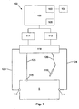
- the apparatus includes a measuring device 100 including a processing system 102 coupled to a signal generator 111 and a sensor 112.
- the signal generator 111 and the sensor 112 are coupled to first electrodes 113, 114, and second electrodes 115, 116, provided on a subject S, via respective first leads 123, 124, and second leads 125, 126.
- the second electrode 116 is in the form of a probe electrode 116 that can be moved over the subject S, during the impedance measurement procedure, as will be described in more detail below.
- connection may be via a switching device 118, such as a multiplexer, allowing the leads 123, 124, 125, 126 to be selectively interconnected to signal generator 111 and the sensor 112, although this is not essential, and connections may be made directly between the signal generator 111 and the first electrodes 113, 114, and the sensor 112 and the second electrodes 115, 116.
- a switching device 118 such as a multiplexer
- An optional external interface 103 can be used to couple the measuring device 100, via wired, wireless or network connections, to one or more peripheral devices 104, such as an external database or computer system, barcode scanner, or the like.
- the processing system 102 will also typically include an I/O device 105, which may be of any suitable form such as a touch screen, a keypad and display, or the like.
- the processing system 102 is adapted to generate control signals, which causes the signal generator 111 to generate one or more alternating signals, such as voltage or current signals, which can be applied to a subject S, via the first electrodes 113,114.
- the sensor 112 determines the voltage across or current through the subject S, using the second electrodes 115, 116 and transfers appropriate signals to the processing system 102.
- the processing system 102 may be any form of processing system which is suitable for generating appropriate control signals and interpreting an indication of the measured signals to thereby determine the subject's bioelectrical impedance, and optionally determine other information such as the presence, absence or degree of oedema, or the like.
- the processing system 102 may therefore be a suitably programmed computer system, such as a laptop, desktop, PDA, smart phone or the like.
- the processing system 102 may be formed from specialised hardware, such as an FPGA (field programmable gate array), or a combination of a programmed computer system and specialised hardware, or the like.
- the processing system 102, the signal generator 111 and the sensor 112 may be integrated into a common housing and therefore form an integrated device.
- the processing system 102 may be connected to the signal generator 111 and the sensor 112 via wired or wireless connections. This allows the processing system 102 to be provided remotely to the signal generator 111 and the sensor 112.
- the signal generator 111 and the sensor 112 may be provided in a unit near, or worn by the subject S, whilst the processing system 102 is situated remotely to the subject S.
- the first electrodes 113, 114 are positioned on the subject to act as drive electrodes allowing one or more signals to be injected into the subject S.
- the location of the first electrodes 113, 114 will depend on the segment of the subject S under study, and can include for example, positioning electrodes on the wrist and ankles of a subject, to allow the impedance of limbs to be determined.
- one or more alternating signals are applied to the subject S, via the first leads 123, 124 and the first electrodes 113, 114.
- the nature of the alternating signal will vary depending on the nature of the measuring device and the subsequent analysis being performed.
- the system can use Bioimpedance Analysis (BIA) in which a single low frequency current is injected into the subject S, with the measured impedance being used directly in the assessment of oedema.
- Bioimpedance Spectroscopy (BIS) devices utilise frequencies ranging from very low frequencies (4 kHz) to higher frequencies (1000 kHz), and can use 256 or more different frequencies within this range, to allow multiple impedance measurements to be made within this range.
- the measuring device 100 may either apply an alternating signal at a single frequency, at a plurality of frequencies simultaneously, or by apply a number of alternating signals at different frequencies sequentially, depending on the preferred implementation.
- the frequency or frequency range of the applied signals may also depend on the analysis being performed.
- the applied signal is a frequency rich current from a current source clamped, or otherwise limited, so it does not exceed a maximum allowable subject auxiliary current.
- voltage signals may be applied, with a current induced in the subject being measured.
- the signal can either be constant current, impulse function or a constant voltage signal where the current is measured so it does not exceed the maximum allowable subject auxiliary current.
- a potential difference and/or current are measured between the second electrodes 115, 116.
- the acquired signal and the measured signal will be a superposition of potentials generated by the human body, such as the ECG, and potentials generated by the applied current.
- the distance between the second electrodes is measured and recorded.
- other parameters relating to the subject such as the height, weight, age, sex, health status, any interventions and the date and time on which they occurred.
- Other information, such as current medication, may also be recorded.
- buffer circuits may be placed in connectors that are used to connect the second electrodes 115, 116 to the second leads 125, 126, as will be described in more detail below. This ensures accurate sensing of the voltage response of the subject S, and in particular helps eliminate contributions to the measured voltage due to the response of the second leads 125, 126, and reduce signal loss.
- a further option is for the voltage to be measured differentially, meaning that the sensor used to measure the potential at each second electrode 115, 116 only needs to measure half of the potential as compared to a single ended system.
- the measurement system may also have buffers placed in the connectors between the first electrodes 113, 114 and the first leads 123, 124.
- current can also be driven or sourced through the subject S differentially, which again greatly reduced the parasitic capacitances by halving the common-mode current.
- Another particular advantage of using a differential system is that the micro-electronics built into the connectors for each first electrode 113, 114 also removes parasitic capacitances that arise when the subject S, and hence the leads first 123, 124, move.
- the acquired signal is demodulated to obtain the impedance of the system at the applied frequencies.
- One suitable method for demodulation of superposed frequencies is to use a Fast Fourier Transform (FFT) algorithm to transform the time domain data to the frequency domain. This is typically used when the applied current signal is a superposition of applied frequencies.
- FFT Fast Fourier Transform
- Another technique not requiring windowing of the measured signal is a sliding window FFT.
- the applied current signals are formed from a sweep of different frequencies, then it is more typical to use a processing technique such as multiplying the measured signal with a reference sine wave and cosine wave derived from the signal generator, or with measured sine and cosine waves, and integrating over a whole number of cycles. This process rejects any harmonic responses and significantly reduces random noise.
- impedance or admittance measurements are determined from the signals at each frequency by comparing the recorded voltage and current signal.
- the demodulation algorithm will produce an amplitude and phase signal at each frequency.
- the processing system 102 causes a current signal to be applied to the subject S, with the induced voltage across the subject S being measured at step 210, with signals representing the measured voltage and the applied current being returned to the processing system 102 for analysis.
- This is typically performed for at least a segment of the subject S that is suspected of being susceptible to oedema, and may also be repeated for a separate healthy segment of the subject.
- this is typically performed on the affected or "at risk” limb (hereinafter generally referred to as the "affected” limb), and may also be performed on the contra-lateral limb.
- the probe electrode 116 will be moved along the length of the respective limb or limb segment, so that a number of measurements are taken over the entire limb or segment length.
- the measurements for a single limb or segment are taken over a time period such as 20 seconds, with measurements being made at a sampling rate of 1ms, thereby providing a total of 20,000 readings for the limb, with the readings being distributed along the limb length.
- any suitable number of readings may be used, although it will be appreciated that the greater the number of measurements made, the higher the resolution of the impedance profile.
- measured voltage and current signals are used by the processing system 102 to determine a sequence of measured impedance values.
- this includes first impedance values representing the impedance profile of the unaffected limb or limb segment and second impedance values representing the impedance profile of the affected limb or limb segment, although this is not essential, and in one example, impedance measurements are only made for the affected limb or limb segment.
- impedance values are determined, these are used by the processing system 102, to derive an impedance profile. This may be achieved in any one of a number of ways depending on the preferred implementation.
- the impedance profile is in the form of a graphical representation showing the variation in the measured impedance values along the length of the limb or limb segment. It will be appreciated that in one example, this involves measuring the position of the probe along the limb or limb segment, allowing the impedance value to be plotted against position. However, a number of variations on this are possible.
- the position can be derived from the impedance values themselves, as some portions of limbs, such as elbow or knee joints, have different impedance values to other portions of the limb, allowing the elbow or knee to be easily identified.
- the impedance profile can be based on parameters derived from measured impedance values, such as the impedance at zero, characteristic or infinite frequencies ( R 0 , Z c , R ⁇ ).
- the impedance profile can be based solely on the impedance measured for the "affected" limb or limb segment. However, alternatively, the impedance profile can also include an indication of the impedances measured for the unaffected limb or limb segment, thereby allowing comparison between the limbs or segments. It will be appreciated that in a healthy person, the impedance of both limbs or corresponding limb segments will be similar, and consequently, differences in the impedance profiles can be used to help identify the presence, absence, degree and/or location of any oedema.
- the impedance profile can include a baseline or other reference.
- the baseline is typically a previous impedance profile measured for the same limb, or limb segment of the subject S, whereas the reference is typically determined from a reference population of healthy individuals, as will be described in more detail below.
- a representation of the impedance profile can be displayed to an operator at step 230, as will be described in more detail below.
- the probe electrode 116 is formed from a housing 300 and a contact surface 301.
- the contact surface 301 is connected via an electrical connection 302 to a connector 303 which allows onward connection to the lead 126 shown in Figure 1 .
- the contact surface 301 is designed to be placed against the subject S, in contact with the subject's skin surface.
- the contact surface 301 is typically formed from an electrically conductive material, such as stainless steel or the like, and may also be coated with an electro-conductive gel.
- the contact surface 301 is formed from a convex curved smooth surface, to assist with smooth transit across the subject's skin, as the probe 116 is moved along the length of the subject's limb, as well as to maximise contact between the contact surface and the subject's skin, thereby ensuring good electrical connection.
- the housing is configured to allow an operator to hold the probe electrode whilst it is placed in contact with the subject. To ensure that this does not interfere with measurements, the housing is typically formed from an electrically insulating material such as a Perspex tube, or the like, although a wide variety of probe arrangements may be used.
- an electrically insulating material such as a Perspex tube, or the like, although a wide variety of probe arrangements may be used.
- the contact surface 301 is provided by a moving member, such as a roller ball arrangement.
- the probe 116 is formed from a housing 310, such as a Perspex tube or the like.
- the housing 310 includes a shaped end portion, shown generally at 311, which forms a mounting adapted to receive a roller ball 312.
- the roller ball 312 is positioned in the shaped portion 311 to allow rotational movement of the roller ball in any direction, whilst constraining translational movement.
- the roller ball 312 is generally formed from an electrically conducted substance such as stainless steel or the like, and may again be coated with an electrically conductive gel.
- a compression spring 313 is mounted in the housing using a mounting (not shown), so that the spring is urged into contact with the roller ball 312 thereby ensuring good electrical contact between the roller ball 312 and the spring 313.
- the spring 313 is then connected via an electrical connection 314 to a connector 315 which in turn allows the probe to be connected to the lead 126.
- any suitable method of electrically connecting the roller ball 312 and the lead 126 may be used, such as brushes, or the like.
- the probe 116 also includes a motion sensing system 316 configured to sense motion of the roller ball 312 and return an indication of the motion via an electrical connection 317. This would typically involve transferring signals indicative of movement of the roller ball 312, via the lead 126, or an appropriate other connection, to the measuring device 100.
- the mechanism for sensing motion of the roller ball 312 may be any appropriate mechanism.
- the sensor 316 can include optical sensors adapted to optically detect movement of the roller ball.
- one or more moving elements, such as wheels, can be placed in contact with the roller ball 312 such that movement of the moving element can be detected.
- the ability to detect motion of a roller ball 312 is technology known from computer mouse or trackball peripheral devices, or the like, and accordingly this will not be described in any further detail.
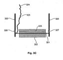
- FIG. 3C A second probe arrangement forming part of the invention is shown at Figure 3C .
- the probe 116 includes two supports 320 which operate to support an axle 321.
- An electrically conductive roller 322, such as a stainless steel roller, is mounted to the axle with the roller 322 being positioned against the subject in use.
- the axle 321, which is also conductive, is connected via an electrical connection 323 to a connector 324 to allow onward connectivity to the lead 126.
- the roller 322 includes an aperture 325 extending therethrough.
- the aperture 325 is positioned so that once per revolution of the roller 322 the aperture 325 aligns with a radiation source 326, such as an LED (light emitting diode) and a corresponding detector 327. Accordingly, when the aperture 325 aligns with the radiation source 326 and detector 327, the detector 327 will detect radiation emitted by the source by allowing revolutions of the roller 322 to be counted. Again information regarding this can be transferred back to the measuring device utilising appropriate connections (not shown).
- subject details are optionally determined and provided to the processing system 102.
- the subject details will typically include information such as limb dominance, details of any medical interventions, as well as information regarding the subject as the subject's age, weight, height, sex, ethnicity or the like.
- the subject details can be used in referencing previous measurements made for the subject, for selecting other baselines or reference normal population values, as well as for generating reports, or the like.
- the subject details may be supplied to the processing system 102 via appropriate input means, such as the I/O device 105.
- appropriate input means such as the I/O device 105.
- the information is input a single time and stored in an appropriate database, or the like, which may be connected as a peripheral device 104 via the external interface 103.
- the database can include subject data representing the subject details, together with information regarding previous impedance profiles, baseline measurements or impedance measurements recorded for the subject.
- the operator can use the processing system 102 to select a search database option allowing the subject details to be retrieved.
- a search database option allowing the subject details to be retrieved.
- This is typically performed on the basis of a subject identifier, such as a unique number assigned to the individual upon admission to a medical institution, or may alternatively be performed on the basis of name or the like.
- a database is generally in the form of an HL7 compliant remote database, although any suitable database may be used.
- the subject can be provided with a wristband or other device, which includes coded data indicative of the subject identifier.
- the measuring device 100 can be coupled to a peripheral device 104, such as a barcode or RFID (Radio Frequency Identification) reader allowing the subject identifier to be detected and provided to the processing system 102, which in turn allows the subject details to be retrieved from the database.
- the processing system 102 can then display an indication of the subject details retrieved from the database, allowing the operator to review these and confirm their accuracy before proceeding further.
- an affected limb may be determined. This may be achieved in any one of a number of ways depending on the preferred implementation.
- the affected limb can be indicated through the use of appropriate input means, such as the I/O device 105.
- this information can be derived directly from the subject details, which may include an indication of the affected limb, or details of any medical interventions performed, which are in turn indicative of the affected limb.
- an operator positions the first electrodes 113, 114, and the second electrode 115 on the subject S, and connects these electrodes to the corresponding leads 123, 124, 125.
- the probe is also connected to the lead 126, if required.
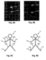
- the general arrangement is to provide electrodes on the hand at the base of the knuckles and between the bony protuberances of the wrist, as shown in Figure 5A , and on the feet at the base of the toes and at the front of the ankle, as shown in Figure 5B .
- the configurations shown in Figures 5C and 5D allow impedance profiles of the right arm 631 and the right leg 633 to be measured respectively, and it will be appreciated that equivalent arrangements can be used to derive impedance profiles for the left leg and left arm.
- the value of the measured impedance will tend to drop, as the theory of equal potentials, indicates that the potential measured at the electrode 115 will be similar to the potential at the shoulder of the right arm 631.
- Electrodes 115 could be placed anywhere along the left arm 632, since the whole arm is at an equal potential, equivalent to if the electrode were positioned at the shoulder.
- the impedance probe is positioned at a start measuring point.
- the start measuring point may vary depending on the particular measurements being made.
- the probe 116 is initially located at the ulnar styloid process.
- the monitoring process is activated at step 430, typically using an appropriate input command provided to the measuring device 100, for example, via the I/O device 105.
- the measuring device 100 applies a current signal to the subject via the first electrodes 113, 114 and concurrently measures the voltage induced across the subject using the second electrode 115 and the probe 116. It will be appreciated that in practice the signal generator 111, and the sensor 112, return signals to the processing system 102 indicative of the applied current and the measured voltage, allowing impedances to be determined.
- the measuring device 100 will determine positional information from the probe. This may be achieved for example by having either the position sensor 316, or signals from the detector 327 transferred to the measuring device 100 and interpreted appropriately.
- step 460 the measuring device 100 determines if the process is complete and if not returns to step 440 to allow further measurements to be performed.
- the operator will slide or roll the probe 116 along the dorsal skin surface towards the acromion, allowing an impedance profile of the entire limb to be determined.
- the probe is held stationery at the beginning and end points for 5 seconds to allow stable end point readings to be determined.
- the measurement of an impedance profile typically takes approximately 20 seconds, although this of course depends on the preferred implementation.
- the user can select an appropriate input command utilising the I/O device 105, allowing the measuring device 100 to determine the process is complete at step 460.
- the measuring device 100 will determine appropriate impedance parameter values, using these to generate impedance profiles at step 480. The manner in which this is achieved will depend on the nature of the impedance measurements performed.
- the value of the impedance parameters R 0 and R ⁇ may be determined in any one of a number of manners such as by:
- the impedance profile is based on the actual measured impedance values, or parameters derived therefrom using suitable techniques.
- measuring devices can take up to 800 msec to complete a frequency scan, in which case the probe may have to be moved at a rate that is too slow for practical purposes to prevent the probe moving a significant distance along the limb during a frequency scan. This in turn effects the usability of the process. Accordingly, in many cases it is preferred to perform measurements at a single selected frequency in the range 5 kHz to 1 MHz at a sampling rate of 1 reading per msec. Using this arrangement, with a twenty second measurement protocol allows 20,000 readings to be established along the length of the arm, thereby allowing a suitable profile to be established. It will be appreciated however that a greater or lesser number of measurements made be used depending for example on the intended use of the measurements.
- derived profiles will now be described.
- the profiles are compared to limb volumes, which are currently a preferred mechanism for determining the presence, absence or degree of oedema.
- ⁇ may be obtained from regression of the impedance quotient, L 2 /Z, against limb volume, measured by a reference technique, such as DEXA (Dual Energy X-ray Absortiometry), MRI (Magnetic Resonance Imaging), perometry, or the like, in an independent group of subjects.
- DEXA Direct Energy X-ray Absortiometry
- MRI Magnetic Resonance Imaging
- Example profiles are shown in Figure 6A .
- This shows example impedance profiles, along both the left and right arms, of a number of test subjects.
- the figure presents the impedances at zero and infinite frequency calculated from BIS measurements for sequential 2.5 cm segments, as well as perometer volume measurements for equivalent segment volumes.
- a limited number of readings can be collected using the probe, or alternatively, the probe could be replaced by a number of second electrodes positioned along the limb.
- the impedance profile along the arm is the inverse of that seen for segment volume as expected from Equation (3), with a high correlation between the impedance and volume measurements being demonstrated.
- the position of the elbow, indicated by a change in volume and impedance is clearly discernable.
- Figure 6B shows the correlation of arm segment volume measured by perometer with that predicted by impedance according to Equation (3).
- limits of agreement between the two methods are variable depending upon the limb region being measured. For example, agreement was closest for the predominantly cylindrical regions of the forearm and biceps/triceps region and worse for the joint regions of the elbow and shoulder.
- FIG. 6D An example of the impedance profile of the arms of a subject with unilateral lymphoedema is shown in Figure 6D .
- the impedance decreases as the electrode is moved from the wrist towards the shoulder reflecting the shortening inter-electrode distance between the second electrode 115 and the probe 116.
- the impedance is higher in the unaffected limb compared to that of the affected limb, highlighting the presence and magnitude of oedema.
- the measuring device 100 when the measuring device 100 presents a measured impedance profile, it can include a reference or baseline measurement.
- a baseline is typically a previous impedance profile created from an impedance profile measurement that has significance in the treatment history of the subject.
- a common baseline in use might be an impedance profile measurement made on a patient suffering from lymphoedema before they start a course of management therapy. This measurement allows the practitioner to gauge accurately how much the patient has improved from the start of their treatment to the present measurement.
- Baseline measurements may also be made pre-surgery and hence pre-lymphoedema, in which case the baseline impedance profile establishes the "normal" healthy impedance profile for the individual patient and can be used thereafter as a benchmark from which to monitor progress of the patient.
- Baselines can also be set using a single measurement or be created from the average of a number of measurements specified by the user.
- the reference is typically formed from an impedance profile derived from a normal population (subject's not suffering from oedema) that is relevant to the subject under study.
- the normal population is typically selected taking into account factors such as medical interventions performed, ethnicity, sex, height, weight, limb dominance, the affected limb, or the like.
- test subject has unilateral lymphoedema of the dominant arm and is female then the normalised data drawn from the normal population database will be calculated from the dominant arm measurements from female subjects that are present in the in the normal population database.
- the processing system 102 typically accesses reference populations stored in the database, or the like. This may be performed automatically by the processing system 102 using the subject details.
- the database may include a look-up table that specifies the normal population that should be used given a particular set of subject details. Alternatively selection may be achieved in accordance with predetermined rules that can be derived using heuristic algorithms based on selections made by medically qualified operators during previous procedures. Alternatively, this may achieved under control of the operator, depending on the preferred implementation.
- Operators may also have their own reference normal populations stored locally. However, in the event that suitable populations are not available, the processing system 102 can be used to retrieve a reference from a central repository, for example via an appropriate server arrangement. In one example, this may be performed on a pay per use basis.
- the reference may also need to be scaled to take into account differing limb lengths of subjects measured, which can be determined from probe positional information if this is present.
- the measured impedance profile can be displayed concurrently with reference impedance profiles representing healthy limbs and representing subjects with oedema, to thereby highlight to the operator whether oedema is likely, and if so, where on the limb this has occurred, or is most severe.
- impedance profiles can be displayed for each limb, thereby allowing comparison between contra-lateral limbs.
- the impedance profile of a healthy limb acts as a baseline or reference against which the profile of the affected limb can be compared.
- Display of the representation may be achieved in a number of ways, such as by presenting the representation on a suitable display, for example, using the I/O device 105, or alternatively by providing the representation in a hard copy form using an appropriate printer, although any suitable technique may be used.
- impedance analysis in the above described manner can be used to focus on the levels of extracellular fluid in the limb, this tends to provide a more accurate assessment of fluid distributions within the limb than volume measurements alone.
- the impedance profiles of Figure 6D include a number of bumps and troughs, particularly in the lymphoedematous limb.
- the impedance profile of Figure 6D indicates not only that there is a difference in fluid levels between the limbs, and hence that there is the presence of lymphoedema, but also can be used to determine in which area of the arm fluid concentrations are highest and/or lowest, thereby allowing highly localised oedema to be diagnosed.
- impedance measurements along the limb or other body segment are achieved by moving a probe along the respective body segment.
- this is not essential, and as an alternative, a sequence of second electrodes not forming part of the invention may be placed along the subject's limb, to allow impedance measurements to be recorded at a number of different locations along the limb.
- Electrodes can be standard electrodes, positioned as required by the operator, an alternative electrode configuration suitable for performing this will now be described with reference to Figures 7A to 7F .
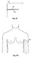
- the electrode is a band electrode 700, which includes a number of separate electrodes.
- the electrode is formed from an elongate substrate 710 such as a plastic polymer coated with shielding material and an overlaying insulating material.
- a number of electrically conductive tracks 720 are provided on the substrate extending from an end of the substrate 711 to respective conductive contact pads 730, spaced apart along the length of the substrate in sequence. This allows a connector to be electrically coupled to the tracks 720 and provide onward connectivity to leads, such as leads 126.
- the tracks 720 and the contact pads 730 may be provided on the substrate 710 in any one of a number of manners, including for example, screen printing, inkjet printing, vapour deposition, or the like, and are typically formed from silver or another similar material. It will be appreciated however that the tracks and contact pads should be formed from similar materials to prevent signal drift. Furthermore, whilst circular contact pads 730 are shown, in practice these could be of any suitable shape.
- an insulating layer 740 is provided having a number of apertures 750 aligned with the electrode contact pads 730.
- the insulating layer is typically formed from a plastic polymer coated with shielding material and an overlaying insulating material.
- a conductive gel 760 to the contact pads 730. It will be appreciated that in this instance gel can be provided into each of the apertures 750 as shown.
- a removable covering 770 is then applied to the electrode, to maintain the electrode's sterility and/or moisture level in the gel.
- This may be in the form of a peel off strip or the like which when removed exposes the conductive gel 760, allowing the electrode to be attached to the subject S.
- each of the tracks 720 comprises a shield track 721, and a signal track 722, as shown. This allows a shield on the leads 126 to be connected to the shield track 721, with the lead core being coupled to the signal track 722. This allows shielding to be provided on the electrode, to help reduce interference between applied and measured signals.
- the band electrode may be attached to a limb segment of the subject, such as the subject's arm, as shown in Figure 7G .
- the electrode will typically include an adhesive surface, allowing it to stick to the subject. This provides an electrode that is easy to attach and position on the subject, and yet can be worn for an extended period if necessary.
- the band electrode 700 may also be positioned on the subject at other locations, such as on the side of the subject's torso, or laterally above the naval, on the leg, or the like.
- the band electrode can be connected to the switching device 118 via respective leads 126, with a separate lead being provided for each contact pad 730.
- the measuring device 100 can control the switching device 118 so that readings are taken from each of the contact pads 730 in turn. This allows readings along the entire body segment to be taken automatically by the measuring device 100, without requiring operator intervention, for example, by requiring the operator move the probe 116 along the subject's body segment.
- the band electrode 700 provides sufficient electrodes to allow an impedance profile to be measured.
- the band electrode includes six electrodes, however any suitable number may be used depending on the preferred implementation.
- the contact pads are provided at definite positions on the band electrode, thereby allowing for easy and accurate determination of the position at which each impedance measurement is made.
Landscapes
- Health & Medical Sciences (AREA)
- Life Sciences & Earth Sciences (AREA)
- Biomedical Technology (AREA)
- Molecular Biology (AREA)
- Veterinary Medicine (AREA)
- Biophysics (AREA)
- Pathology (AREA)
- Engineering & Computer Science (AREA)
- Public Health (AREA)
- Heart & Thoracic Surgery (AREA)
- Medical Informatics (AREA)
- Physics & Mathematics (AREA)
- Surgery (AREA)
- Animal Behavior & Ethology (AREA)
- General Health & Medical Sciences (AREA)
- Nuclear Medicine, Radiotherapy & Molecular Imaging (AREA)
- Radiology & Medical Imaging (AREA)
- Measurement And Recording Of Electrical Phenomena And Electrical Characteristics Of The Living Body (AREA)
- Investigating Or Analyzing Materials By The Use Of Electric Means (AREA)
Description
- The present invention relates to a method and apparatus for use in analysing impedance measurements performed on a subject, and in particular to a probe that can be used in determining a limb impedance profile, which can in turn be used in determining the presence, absence or degree of oedema in a subject's limb.
- The reference in this specification to any prior publication (or information derived from it), or to any matter which is known, is not, and should not be taken as an acknowledgment or admission or any form of suggestion that the prior publication (or information derived from it) or known matter forms part of the common general knowledge in the field of endeavour to which this specification relates.
- Lymphoedema is a condition characterised by excess protein and oedema in the tissues as a result of reduced lymphatic transport capacity and/or reduced tissue proteolytic capacity in the presence of a normal lymphatic load. Acquired, or secondary lymphoedema, is caused by damaged or blocked lymphatic vessels. The commonest inciting events are surgery and/or radiotherapy.
- For example, upper limb lymphoedema is a common sequela of treatment for breast cancer. Estimates of the incidence of breast cancer lymphedoema vary in the medical literature from low values in the range of 9%-10% to those that exceed 50%. Lymphoedema is associated with a reduced quality of life, particularly emotional, social and physical function, as well as body image and lifestyle.
- The condition is incurable and has been found difficult to treat with drugs or surgery but symptomatic treatment by complex physical therapy has been shown to benefit patients. Critical to patient management is that the extent of lymphoedema be measured regularly to assess patient's progress. A decrease in limb size not only indicates that treatment is beneficial but also helps encourage patient compliance with a demanding treatment programme. Additionally, onset of lymphoedema is unpredictable and may develop within days of its cause or at any time during a period of many years after that cause.
- Accordingly, there is a need to be able to easily monitor for and diagnose the presence or degree of lymphodema. A variety of methods have been used ranging in complexity from sophisticated imaging techniques such as MRI to simple geometrical volume calculations from limb circumference measurements. However, these techniques are either too costly, in the case of MRI, or insufficiently accurate in the case of limb circumference.
- One existing technique for determining biological parameters relating to a subject, such as fluid levels, involves the use of bioelectrical impedance. This involves measuring the electrical impedance of a subject's body using a series of electrodes placed on the skin surface. Changes in electrical impedance at the body's surface are used to determine parameters, such as changes in fluid levels, associated with the cardiac cycle or oedema.
-
WO00/79255 - However, whilst such techniques can be used to determine the presence of oedema over an entire limb, lymphoedema can be highly localised, and as the resolution of such techniques can be limited, this makes the detection of such localised oedema difficult.
-
US 2007/106342 describes an electronic pain treatment device delivering electrical energy to the tissue of a patient in pain, which includes a variable wave generator, an impedance measurement circuit, and at least one electrode probe. Associated methods for treating pain are also disclosed. -
GB 2,426,824 -
US 6,714,814 describes an impedance measuring apparatus which is easy to use, and which is guaranteed to be free of incorrect measurement caused by some joints appearing in the current flowing passage intervening between two selected body parts and by the indefinite length between two selected body parts. The measuring apparatus of the present invention limits the place of the body under measurement to "one body region", i.e. a selected joint-to-joint body portion or joint-free body portion such as the forearm extending from the wrist to the elbow or the portion extending from the ankle to the knee, and comprises a housing having a contact surface to be applied to one selected body region; a first pair of measurement current supplying electrodes so placed on the contact surface that the one selected body region may be put in contact with the current electrodes; and a first pair of voltage measuring electrodes so placed on the contact surface between the pair of current electrodes that the one selected body region may be put in contact with the voltage electrodes. -
DE 2912349 describes a probe for measuring water content of the human skin. The system operates by measuring the resistance of the skin between two electrodes provided a set distance apart on the probe. - In a first broad form the present invention provides apparatus as defined by
claim 1 for use in performing impedance measurements on a subject. - Typically the housing is an elongate housing, the contact surface is provided at a first end of the housing and the connector is provided at a second opposing end of the housing.
- Typically the housing is formed from an insulating material.
- Typically the housing is formed from a perspex tube.
- Typically the contact surface has a convex shape.
- The contact surface includes a moving member for moving relative to the subject.
- Typically the moving member is a roller ball, and wherein the housing includes a shaped mounting for receiving the roller ball.
- Typically the moving member is a cylindrical roller mounted on an axle.
- Typically the probe includes a contact for electrically connecting the moving member to the connecter.
- Typically the contact is a spring.
- The probe includes a sensor for sensing movement of the moving member.
- Typically the sensor includes at least one of:
- a) an optical sensor; and,
- b) moving elements in contact with the moving member.
- Typically the connector is for connecting to a lead of the measuring device.
- Typically, in use, the probe is moved along a segment of the subject to thereby allow an impedance profile representing variations in impedance along the segment to be determined.
- Typically, the measuring device includes a processing system for:
- a) causing at least one electrical signal to be applied to the subject via first electrodes provided on the subject; and,
- b) determining an indication indicative of at least one second electrical signal measured via a second electrode positioned on the subject, and via the probe.
- In a second broad form the present invention provides a method of performing impedance measurements on a subject using a probe as defined by claim 9.
- Typically the method includes, in the measuring device, displaying a representation of the impedance profile to thereby allow the impedance profile to be used in determining a presence, absence, degree or location of oedema in the subject.
- Typically the method includes, in the measuring device:
- a) causing a sequence of first electrical signals to be applied to the subject via first electrodes provided on the subject; and,
- b) determining an indication of a sequence of second electrical signals measured via a second electrode positioned on the subject, and via the probe.
- Typically the method includes, in the measuring device: using an indication of the first and second signals to determine an impedance profile, the impedance profile representing variations in measured impedance along the segment.
- It will be appreciated that the broad forms of the invention may be used individually or in combination, and may be used for diagnosis of the presence, absence or degree of a range of conditions and illnesses, including, but not limited to oedema, lymphoedema, body composition and the like.
- An example of the present invention will now be described with reference to the accompanying drawings, in which: -
-
Figure 1 is a schematic diagram of an example of impedance determination apparatus; -
Figure 2 is a flowchart of an example of a process for determining an impedance profile; -
Figures 3A to 3C are schematic diagrams of examples of impedance measuring probes; -
Figure 4 is a flowchart of an example of a process for determining an impedance profile for uni-lateral limb oedema; -
Figures 5A and 5B are diagrams of examples of electrode positions for use in measuring limb impedances; -
Figures 5C and 5D are schematic diagrams of examples of electrode positions for use in measuring limb impedances; -
Figure 6A is a graphical representation of an example of a profile of typical arm volume and impedance; -
Figure 6B is a graphical representation of an example of a correlation of arm segment volume measured using a perometer with that predicted by impedance; -
Figure 6C is a graphical representation of an example of limits of agreement between measured and predicted segment volumes; -
Figure 6D is a graphical representation of an example of impedance profiles of an arm with lymphoedema and a contralateral unaffected arm; and, -
Figure 6E is a graphical representation of an example of cumulative limb volumes measured by perometry from wrist to shoulder. -
Figures 7A to 7F are schematic diagrams of an example of the construction of a band electrode not forming part of the invention; -
Figure 7G is a schematic diagram of the use of a band electrode not forming part of the invention; - An example of apparatus suitable for performing an analysis of a subject's bioelectric impedance will now be described with reference to
Figure 1 . - As shown the apparatus includes a
measuring device 100 including aprocessing system 102 coupled to asignal generator 111 and asensor 112. In use thesignal generator 111 and thesensor 112 are coupled tofirst electrodes second electrodes first leads second electrode 116 is in the form of aprobe electrode 116 that can be moved over the subject S, during the impedance measurement procedure, as will be described in more detail below. - The connection may be via a
switching device 118, such as a multiplexer, allowing theleads generator 111 and thesensor 112, although this is not essential, and connections may be made directly between thesignal generator 111 and thefirst electrodes sensor 112 and thesecond electrodes - An optional
external interface 103 can be used to couple themeasuring device 100, via wired, wireless or network connections, to one or moreperipheral devices 104, such as an external database or computer system, barcode scanner, or the like. Theprocessing system 102 will also typically include an I/O device 105, which may be of any suitable form such as a touch screen, a keypad and display, or the like. - In use, the
processing system 102 is adapted to generate control signals, which causes thesignal generator 111 to generate one or more alternating signals, such as voltage or current signals, which can be applied to a subject S, via the first electrodes 113,114. Thesensor 112 then determines the voltage across or current through the subject S, using thesecond electrodes processing system 102. - Accordingly, it will be appreciated that the
processing system 102 may be any form of processing system which is suitable for generating appropriate control signals and interpreting an indication of the measured signals to thereby determine the subject's bioelectrical impedance, and optionally determine other information such as the presence, absence or degree of oedema, or the like. - The
processing system 102 may therefore be a suitably programmed computer system, such as a laptop, desktop, PDA, smart phone or the like. Alternatively theprocessing system 102 may be formed from specialised hardware, such as an FPGA (field programmable gate array), or a combination of a programmed computer system and specialised hardware, or the like. - It will be appreciated that the
processing system 102, thesignal generator 111 and thesensor 112 may be integrated into a common housing and therefore form an integrated device. Alternatively, theprocessing system 102 may be connected to thesignal generator 111 and thesensor 112 via wired or wireless connections. This allows theprocessing system 102 to be provided remotely to thesignal generator 111 and thesensor 112. Thus, thesignal generator 111 and thesensor 112 may be provided in a unit near, or worn by the subject S, whilst theprocessing system 102 is situated remotely to the subject S. - In use, the
first electrodes first electrodes - Once the
second electrodes first electrodes - For example, the system can use Bioimpedance Analysis (BIA) in which a single low frequency current is injected into the subject S, with the measured impedance being used directly in the assessment of oedema. In contrast Bioimpedance Spectroscopy (BIS) devices utilise frequencies ranging from very low frequencies (4 kHz) to higher frequencies (1000 kHz), and can use 256 or more different frequencies within this range, to allow multiple impedance measurements to be made within this range.
- Thus, the measuring
device 100 may either apply an alternating signal at a single frequency, at a plurality of frequencies simultaneously, or by apply a number of alternating signals at different frequencies sequentially, depending on the preferred implementation. The frequency or frequency range of the applied signals may also depend on the analysis being performed. - In one example, the applied signal is a frequency rich current from a current source clamped, or otherwise limited, so it does not exceed a maximum allowable subject auxiliary current. However, alternatively, voltage signals may be applied, with a current induced in the subject being measured. The signal can either be constant current, impulse function or a constant voltage signal where the current is measured so it does not exceed the maximum allowable subject auxiliary current.
- A potential difference and/or current are measured between the
second electrodes - The distance between the second electrodes is measured and recorded. Similarly, other parameters relating to the subject may be recorded, such as the height, weight, age, sex, health status, any interventions and the date and time on which they occurred. Other information, such as current medication, may also be recorded.
- To assist accurate measurement of the impedance, buffer circuits may be placed in connectors that are used to connect the
second electrodes - This in turn greatly reduces artefacts caused by movement of the second leads 125, 126, which is particularly important in some applications such as monitoring fluid levels during dialysis, in which sessions usually last for several hours and the subject will move around and change positions during this time, as well as being important during movement of the
probe 116. - A further option is for the voltage to be measured differentially, meaning that the sensor used to measure the potential at each
second electrode - The measurement system may also have buffers placed in the connectors between the
first electrodes first electrode - The acquired signal is demodulated to obtain the impedance of the system at the applied frequencies. One suitable method for demodulation of superposed frequencies is to use a Fast Fourier Transform (FFT) algorithm to transform the time domain data to the frequency domain. This is typically used when the applied current signal is a superposition of applied frequencies. Another technique not requiring windowing of the measured signal is a sliding window FFT.
- In the event that the applied current signals are formed from a sweep of different frequencies, then it is more typical to use a processing technique such as multiplying the measured signal with a reference sine wave and cosine wave derived from the signal generator, or with measured sine and cosine waves, and integrating over a whole number of cycles. This process rejects any harmonic responses and significantly reduces random noise.
- Other suitable digital and analog demodulation techniques will be known to persons skilled in the field.
- In the case of BIS, impedance or admittance measurements are determined from the signals at each frequency by comparing the recorded voltage and current signal. The demodulation algorithm will produce an amplitude and phase signal at each frequency.
- An example of the operation of the apparatus to generate an impedance profile will now be described with reference to
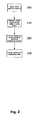
Figure 2 . - In this example, at
step 200 theprocessing system 102 causes a current signal to be applied to the subject S, with the induced voltage across the subject S being measured atstep 210, with signals representing the measured voltage and the applied current being returned to theprocessing system 102 for analysis. - This is typically performed for at least a segment of the subject S that is suspected of being susceptible to oedema, and may also be repeated for a separate healthy segment of the subject. Thus, for example, in the case of limb oedema, this is typically performed on the affected or "at risk" limb (hereinafter generally referred to as the "affected" limb), and may also be performed on the contra-lateral limb.
- During this process, the
probe electrode 116 will be moved along the length of the respective limb or limb segment, so that a number of measurements are taken over the entire limb or segment length. In one example, the measurements for a single limb or segment are taken over a time period such as 20 seconds, with measurements being made at a sampling rate of 1ms, thereby providing a total of 20,000 readings for the limb, with the readings being distributed along the limb length. However, any suitable number of readings may be used, although it will be appreciated that the greater the number of measurements made, the higher the resolution of the impedance profile. - It will be appreciated that the application of the current and voltage signals may be controlled by a separate processing system to that used in performing the analysis to derive an impedance profile, and that the use of a single processing system is for the purpose of example only.
- At
step 220, measured voltage and current signals are used by theprocessing system 102 to determine a sequence of measured impedance values. In one example, this includes first impedance values representing the impedance profile of the unaffected limb or limb segment and second impedance values representing the impedance profile of the affected limb or limb segment, although this is not essential, and in one example, impedance measurements are only made for the affected limb or limb segment. - Once the impedance values are determined, these are used by the
processing system 102, to derive an impedance profile. This may be achieved in any one of a number of ways depending on the preferred implementation. - In one example, the impedance profile is in the form of a graphical representation showing the variation in the measured impedance values along the length of the limb or limb segment. It will be appreciated that in one example, this involves measuring the position of the probe along the limb or limb segment, allowing the impedance value to be plotted against position. However, a number of variations on this are possible.
- For example, it can be assumed that movement of the probe along the limb is performed at a relatively constant rate, in which case subsequently sampled measurements will be evenly spaced with respect to each other, on the resulting profile. Alternatively, the position can be derived from the impedance values themselves, as some portions of limbs, such as elbow or knee joints, have different impedance values to other portions of the limb, allowing the elbow or knee to be easily identified.
- Additionally, or alternatively, the impedance profile can be based on parameters derived from measured impedance values, such as the impedance at zero, characteristic or infinite frequencies (R0 , Zc , R ∞).
- The impedance profile can be based solely on the impedance measured for the "affected" limb or limb segment. However, alternatively, the impedance profile can also include an indication of the impedances measured for the unaffected limb or limb segment, thereby allowing comparison between the limbs or segments. It will be appreciated that in a healthy person, the impedance of both limbs or corresponding limb segments will be similar, and consequently, differences in the impedance profiles can be used to help identify the presence, absence, degree and/or location of any oedema.
- Additionally, and/or alternatively, the impedance profile can include a baseline or other reference. The baseline is typically a previous impedance profile measured for the same limb, or limb segment of the subject S, whereas the reference is typically determined from a reference population of healthy individuals, as will be described in more detail below.
- Once the impedance profile is determined, a representation of the impedance profile can be displayed to an operator at
step 230, as will be described in more detail below. - A first example of a probe electrode not forming part of the invention for use in determining an impedance profile will now be described with reference to
Figure 3A . - In this example, the
probe electrode 116 is formed from ahousing 300 and acontact surface 301. Thecontact surface 301 is connected via anelectrical connection 302 to aconnector 303 which allows onward connection to thelead 126 shown inFigure 1 . - In use the
contact surface 301 is designed to be placed against the subject S, in contact with the subject's skin surface. To ensure accurate measurements are obtained, it is important to ensure good electrical contact between thecontact surface 301 and the subject S, and accordingly, thecontact surface 301 is typically formed from an electrically conductive material, such as stainless steel or the like, and may also be coated with an electro-conductive gel. In this example, thecontact surface 301 is formed from a convex curved smooth surface, to assist with smooth transit across the subject's skin, as theprobe 116 is moved along the length of the subject's limb, as well as to maximise contact between the contact surface and the subject's skin, thereby ensuring good electrical connection. - The housing is configured to allow an operator to hold the probe electrode whilst it is placed in contact with the subject. To ensure that this does not interfere with measurements, the housing is typically formed from an electrically insulating material such as a Perspex tube, or the like, although a wide variety of probe arrangements may be used.
- Alternative probe arrangements are shown in
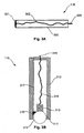
Figures 3B and3C . - In the embodiment of the invention of
Figure 3B thecontact surface 301 is provided by a moving member, such as a roller ball arrangement. Accordingly in this instance theprobe 116 is formed from ahousing 310, such as a Perspex tube or the like. Thehousing 310 includes a shaped end portion, shown generally at 311, which forms a mounting adapted to receive a roller ball 312. - The roller ball 312 is positioned in the shaped
portion 311 to allow rotational movement of the roller ball in any direction, whilst constraining translational movement. The roller ball 312 is generally formed from an electrically conducted substance such as stainless steel or the like, and may again be coated with an electrically conductive gel. - A
compression spring 313 is mounted in the housing using a mounting (not shown), so that the spring is urged into contact with the roller ball 312 thereby ensuring good electrical contact between the roller ball 312 and thespring 313. Thespring 313 is then connected via anelectrical connection 314 to aconnector 315 which in turn allows the probe to be connected to thelead 126. However, any suitable method of electrically connecting the roller ball 312 and thelead 126 may be used, such as brushes, or the like. - In addition to the provision of the roller ball 312, in this embodiment the
probe 116 also includes amotion sensing system 316 configured to sense motion of the roller ball 312 and return an indication of the motion via anelectrical connection 317. This would typically involve transferring signals indicative of movement of the roller ball 312, via thelead 126, or an appropriate other connection, to themeasuring device 100. - It will be appreciated by persons skilled in the art that the mechanism for sensing motion of the roller ball 312 may be any appropriate mechanism. Thus, for example, the
sensor 316 can include optical sensors adapted to optically detect movement of the roller ball. Alternatively, one or more moving elements, such as wheels, can be placed in contact with the roller ball 312 such that movement of the moving element can be detected. It will be appreciated that the ability to detect motion of a roller ball 312 is technology known from computer mouse or trackball peripheral devices, or the like, and accordingly this will not be described in any further detail. - A second probe arrangement forming part of the invention is shown at
Figure 3C . In this embodiment theprobe 116 includes twosupports 320 which operate to support anaxle 321. An electricallyconductive roller 322, such as a stainless steel roller, is mounted to the axle with theroller 322 being positioned against the subject in use. Theaxle 321, which is also conductive, is connected via anelectrical connection 323 to aconnector 324 to allow onward connectivity to thelead 126. - In this embodiment, motion of the
roller 322, for example to detect the distance moved by theprobe 116 along a limb, can be detected in any one of a number of ways. In this embodiment, theroller 322 includes anaperture 325 extending therethrough. Theaperture 325 is positioned so that once per revolution of theroller 322 theaperture 325 aligns with aradiation source 326, such as an LED (light emitting diode) and acorresponding detector 327. Accordingly, when theaperture 325 aligns with theradiation source 326 anddetector 327, thedetector 327 will detect radiation emitted by the source by allowing revolutions of theroller 322 to be counted. Again information regarding this can be transferred back to the measuring device utilising appropriate connections (not shown). - Operation of the
probe 116 for use in determining the impedance profile of the subject's limb will now be described with reference toFigure 4 . For the purpose of this example, measurements to determine a profile are performed along the entire length of the limb, but it will be appreciated that this can also be applied to limb segment or other body segments. - In this example, at
step 400 subject details are optionally determined and provided to theprocessing system 102. The subject details will typically include information such as limb dominance, details of any medical interventions, as well as information regarding the subject as the subject's age, weight, height, sex, ethnicity or the like. The subject details can be used in referencing previous measurements made for the subject, for selecting other baselines or reference normal population values, as well as for generating reports, or the like. - It will be appreciated that the subject details may be supplied to the
processing system 102 via appropriate input means, such as the I/O device 105. Thus, each time a subject measurement is performed this information can be input into the measuringdevice 100. - However, more typically the information is input a single time and stored in an appropriate database, or the like, which may be connected as a
peripheral device 104 via theexternal interface 103. The database can include subject data representing the subject details, together with information regarding previous impedance profiles, baseline measurements or impedance measurements recorded for the subject. - In this instance, when the operator is required to provide subject details, the operator can use the
processing system 102 to select a search database option allowing the subject details to be retrieved. This is typically performed on the basis of a subject identifier, such as a unique number assigned to the individual upon admission to a medical institution, or may alternatively be performed on the basis of name or the like. Such a database is generally in the form of an HL7 compliant remote database, although any suitable database may be used. - In one example, the subject can be provided with a wristband or other device, which includes coded data indicative of the subject identifier. In this case, the measuring
device 100 can be coupled to aperipheral device 104, such as a barcode or RFID (Radio Frequency Identification) reader allowing the subject identifier to be detected and provided to theprocessing system 102, which in turn allows the subject details to be retrieved from the database. Theprocessing system 102 can then display an indication of the subject details retrieved from the database, allowing the operator to review these and confirm their accuracy before proceeding further. - As part of this process, an affected limb, or "at risk" limb, may be determined. This may be achieved in any one of a number of ways depending on the preferred implementation. Thus, for example, the affected limb can be indicated through the use of appropriate input means, such as the I/
O device 105. Alternatively this information can be derived directly from the subject details, which may include an indication of the affected limb, or details of any medical interventions performed, which are in turn indicative of the affected limb. - At
step 410 an operator positions thefirst electrodes second electrode 115 on the subject S, and connects these electrodes to the corresponding leads 123, 124, 125. The probe is also connected to thelead 126, if required. - The general arrangement is to provide electrodes on the hand at the base of the knuckles and between the bony protuberances of the wrist, as shown in
Figure 5A , and on the feet at the base of the toes and at the front of the ankle, as shown inFigure 5B . The configurations shown inFigures 5C and 5D allow impedance profiles of theright arm 631 and theright leg 633 to be measured respectively, and it will be appreciated that equivalent arrangements can be used to derive impedance profiles for the left leg and left arm. - As a result of the electrode positioning, as the
probe 116 is moved from the wrist towards the shoulder along theright arm 631, the value of the measured impedance will tend to drop, as the theory of equal potentials, indicates that the potential measured at theelectrode 115 will be similar to the potential at the shoulder of theright arm 631. - It will be appreciated that using an electrode arrangement in this manner allows the electrode positions to provide reproducible results for impedance measurements. For example when current is injected between
electrodes Figure 5C , theelectrode 115 could be placed anywhere along theleft arm 632, since the whole arm is at an equal potential, equivalent to if the electrode were positioned at the shoulder. - This is advantageous as it greatly reduces the variations in measurements caused by poor placement of the electrodes by the operator. It also greatly reduces the number of electrodes required to perform segmental body measurements, as well as allowing the limited connections shown to be used to measure each of limbs separately.
- However, it will be appreciated that any suitable electrode and lead arrangement may be used.
- At
step 420 the impedance probe is positioned at a start measuring point. The start measuring point may vary depending on the particular measurements being made. Thus for example, in determining an arm limb impedance profile theprobe 116 is initially located at the ulnar styloid process. Once the impedance probe is appropriately positioned the monitoring process is activated atstep 430, typically using an appropriate input command provided to themeasuring device 100, for example, via the I/O device 105. - At
step 440 the measuringdevice 100 applies a current signal to the subject via thefirst electrodes second electrode 115 and theprobe 116. It will be appreciated that in practice thesignal generator 111, and thesensor 112, return signals to theprocessing system 102 indicative of the applied current and the measured voltage, allowing impedances to be determined. - At
step 450 the measuringdevice 100 will determine positional information from the probe. This may be achieved for example by having either theposition sensor 316, or signals from thedetector 327 transferred to themeasuring device 100 and interpreted appropriately. - At
step 460 the measuringdevice 100 determines if the process is complete and if not returns to step 440 to allow further measurements to be performed. - It will be appreciated by persons skilled in the art that whilst this is being performed the operator will slide or roll the
probe 116 along the dorsal skin surface towards the acromion, allowing an impedance profile of the entire limb to be determined. In one example, the probe is held stationery at the beginning and end points for 5 seconds to allow stable end point readings to be determined. In this example, the measurement of an impedance profile typically takes approximately 20 seconds, although this of course depends on the preferred implementation. - Once the probe has been positioned at the acromion, the user can select an appropriate input command utilising the I/
O device 105, allowing the measuringdevice 100 to determine the process is complete atstep 460. - At
step 470 the measuringdevice 100 will determine appropriate impedance parameter values, using these to generate impedance profiles atstep 480. The manner in which this is achieved will depend on the nature of the impedance measurements performed. - In the case of BIS analysis, the impedance profile can be based on impedance parameter values, such as values of the impedance at zero, characteristic or infinite frequencies (R0 , Zc, R ∞). These values can be derived based on the impedance response of the subject, which at a first level can be modelled using equation (1), commonly referred to as the Cole model:

where: - R ∞= impedance at infinite applied frequency,
- R0 = impedance at zero applied frequency,
- ω = angular frequency,
- τ is the time constant of a capacitive circuit modelling the subject response.
- However, the above represents an idealised situation which does not take into account the fact that the cell membrane is an imperfect capacitor. Taking this into account leads to a modified model in which:

where: - α has a value between 0 and 1 and can be thought of as an indicator of the deviation of a real system from the ideal model.
- The value of the impedance parameters R0 and R∞ may be determined in any one of a number of manners such as by:
- solving simultaneous equations based on the impedance values determined at different frequencies;
- using iterative mathematical techniques;
- extrapolation from a "Wessel plot";
- performing a function fitting technique, such as the use of a polynomial function.
- Alternatively, in the case of a BIA analysis, the impedance profile is based on the actual measured impedance values, or parameters derived therefrom using suitable techniques.
- It will be appreciated that whilst BIS analysis generally leads to an improved range of information, time constraints may limit its usage. For example, some examples measuring devices can take up to 800 msec to complete a frequency scan, in which case the probe may have to be moved at a rate that is too slow for practical purposes to prevent the probe moving a significant distance along the limb during a frequency scan. This in turn effects the usability of the process. Accordingly, in many cases it is preferred to perform measurements at a single selected frequency in the range 5 kHz to 1 MHz at a sampling rate of 1 reading per msec. Using this arrangement, with a twenty second measurement protocol allows 20,000 readings to be established along the length of the arm, thereby allowing a suitable profile to be established. It will be appreciated however that a greater or lesser number of measurements made be used depending for example on the intended use of the measurements.
- Examples of derived profiles will now be described. For the purpose of this example, the profiles are compared to limb volumes, which are currently a preferred mechanism for determining the presence, absence or degree of oedema.
- In this regard, the volume of a cylindrical body can be determined from measurements of its length and impedance according to the relationship:

where: - L is length (cm),
- Z is impedance (ohm); and,
- ρ is the resistivity constant (ohm.cm).
- Since a short segment of a limb approximates a cylinder, if the impedance (Z) of the segment is measured then the volume of the limb segment can be estimated. The value of ρ may be obtained from regression of the impedance quotient, L2/Z, against limb volume, measured by a reference technique, such as DEXA (Dual Energy X-ray Absortiometry), MRI (Magnetic Resonance Imaging), perometry, or the like, in an independent group of subjects.
- Example profiles are shown in
Figure 6A . This shows example impedance profiles, along both the left and right arms, of a number of test subjects. The figure presents the impedances at zero and infinite frequency calculated from BIS measurements for sequential 2.5 cm segments, as well as perometer volume measurements for equivalent segment volumes. In this example, in which measurements are collected for segments only, a limited number of readings can be collected using the probe, or alternatively, the probe could be replaced by a number of second electrodes positioned along the limb. - The impedance profile along the arm is the inverse of that seen for segment volume as expected from Equation (3), with a high correlation between the impedance and volume measurements being demonstrated. The position of the elbow, indicated by a change in volume and impedance is clearly discernable.
-
Figure 6B shows the correlation of arm segment volume measured by perometer with that predicted by impedance according to Equation (3). As shown, inFigure 6C , limits of agreement between the two methods are variable depending upon the limb region being measured. For example, agreement was closest for the predominantly cylindrical regions of the forearm and biceps/triceps region and worse for the joint regions of the elbow and shoulder. - An example of the impedance profile of the arms of a subject with unilateral lymphoedema is shown in
Figure 6D . As shown in this example, the impedance decreases as the electrode is moved from the wrist towards the shoulder reflecting the shortening inter-electrode distance between thesecond electrode 115 and theprobe 116. Furthermore, the impedance is higher in the unaffected limb compared to that of the affected limb, highlighting the presence and magnitude of oedema. - It will be appreciated from this that when the measuring
device 100 presents a measured impedance profile, it can include a reference or baseline measurement. - For example, a baseline is typically a previous impedance profile created from an impedance profile measurement that has significance in the treatment history of the subject. A common baseline in use might be an impedance profile measurement made on a patient suffering from lymphoedema before they start a course of management therapy. This measurement allows the practitioner to gauge accurately how much the patient has improved from the start of their treatment to the present measurement.
- Baseline measurements may also be made pre-surgery and hence pre-lymphoedema, in which case the baseline impedance profile establishes the "normal" healthy impedance profile for the individual patient and can be used thereafter as a benchmark from which to monitor progress of the patient. Baselines can also be set using a single measurement or be created from the average of a number of measurements specified by the user.
- The reference is typically formed from an impedance profile derived from a normal population (subject's not suffering from oedema) that is relevant to the subject under study. Thus, the normal population is typically selected taking into account factors such as medical interventions performed, ethnicity, sex, height, weight, limb dominance, the affected limb, or the like.
- Therefore if the test subject has unilateral lymphoedema of the dominant arm and is female then the normalised data drawn from the normal population database will be calculated from the dominant arm measurements from female subjects that are present in the in the normal population database.
- Accordingly, at this stage the
processing system 102 typically accesses reference populations stored in the database, or the like. This may be performed automatically by theprocessing system 102 using the subject details. Thus for example, the database may include a look-up table that specifies the normal population that should be used given a particular set of subject details. Alternatively selection may be achieved in accordance with predetermined rules that can be derived using heuristic algorithms based on selections made by medically qualified operators during previous procedures. Alternatively, this may achieved under control of the operator, depending on the preferred implementation. - Operators may also have their own reference normal populations stored locally. However, in the event that suitable populations are not available, the
processing system 102 can be used to retrieve a reference from a central repository, for example via an appropriate server arrangement. In one example, this may be performed on a pay per use basis. - The reference may also need to be scaled to take into account differing limb lengths of subjects measured, which can be determined from probe positional information if this is present.
- In this instance, the measured impedance profile can be displayed concurrently with reference impedance profiles representing healthy limbs and representing subjects with oedema, to thereby highlight to the operator whether oedema is likely, and if so, where on the limb this has occurred, or is most severe.
- Additionally, and/or alternatively, in the case of unilateral oedema, impedance profiles can be displayed for each limb, thereby allowing comparison between contra-lateral limbs. Thus, in this example, the impedance profile of a healthy limb acts as a baseline or reference against which the profile of the affected limb can be compared.
- Display of the representation may be achieved in a number of ways, such as by presenting the representation on a suitable display, for example, using the I/
O device 105, or alternatively by providing the representation in a hard copy form using an appropriate printer, although any suitable technique may be used. - An example of comparable cumulative volume measurements are shown in
Figure 6E , highlighting that the magnitude difference obtained between arms is greater for the impedance measurements (Figure 6D ) than the equivalent volume measurements (Figure 6E ). - Furthermore, as impedance analysis in the above described manner can be used to focus on the levels of extracellular fluid in the limb, this tends to provide a more accurate assessment of fluid distributions within the limb than volume measurements alone.
- In particular, it can be seen that whilst the volumetric measurements in
Figure 6E present a smooth curve, implying there is a relatively equal distribution of fluid along the limb, the impedance profiles ofFigure 6D include a number of bumps and troughs, particularly in the lymphoedematous limb. Thus, the impedance profile ofFigure 6D indicates not only that there is a difference in fluid levels between the limbs, and hence that there is the presence of lymphoedema, but also can be used to determine in which area of the arm fluid concentrations are highest and/or lowest, thereby allowing highly localised oedema to be diagnosed. - In the example of
Figure 6D , it can be seen that there is a significant peak shown at 600 which was obtained near the start of the reading cycle. This suggests that a segment in the arm near the wrist has a high fluid level thereby indicative of lymphoedema. It is also noticeable that towards the end of the profile the readings are similar to the readings for the control arm and hence that the lymphoedema is prevalent primarily in the lower limb. - Accordingly, by correlating the impedance measurements with the distance travelled along the arm or other limb it is possible not only to detect that the limb is lymphoedematous but also the particular location of lymphoedema within the limb thereby rendering it easier to detect the presence, absence, degree or location of oedema using impedance profiling than volumetric measurements.
- In the above described examples, impedance measurements along the limb or other body segment are achieved by moving a probe along the respective body segment. However, this is not essential, and as an alternative, a sequence of second electrodes not forming part of the invention may be placed along the subject's limb, to allow impedance measurements to be recorded at a number of different locations along the limb.
- Whilst the electrodes can be standard electrodes, positioned as required by the operator, an alternative electrode configuration suitable for performing this will now be described with reference to
Figures 7A to 7F . - In this particular example not forming part of the invention the electrode is a
band electrode 700, which includes a number of separate electrodes. In this example the electrode is formed from anelongate substrate 710 such as a plastic polymer coated with shielding material and an overlaying insulating material. - A number of electrically
conductive tracks 720 are provided on the substrate extending from an end of thesubstrate 711 to respectiveconductive contact pads 730, spaced apart along the length of the substrate in sequence. This allows a connector to be electrically coupled to thetracks 720 and provide onward connectivity to leads, such as leads 126. - The
tracks 720 and thecontact pads 730 may be provided on thesubstrate 710 in any one of a number of manners, including for example, screen printing, inkjet printing, vapour deposition, or the like, and are typically formed from silver or another similar material. It will be appreciated however that the tracks and contact pads should be formed from similar materials to prevent signal drift. Furthermore, whilstcircular contact pads 730 are shown, in practice these could be of any suitable shape. - Following the application of the
contact pads 730 and thetracks 720, an insulatinglayer 740 is provided having a number ofapertures 750 aligned with theelectrode contact pads 730. The insulating layer is typically formed from a plastic polymer coated with shielding material and an overlaying insulating material. - To ensure adequate conduction between the
contact pads 730, and the subject S, it is typical to apply aconductive gel 760 to thecontact pads 730. It will be appreciated that in this instance gel can be provided into each of theapertures 750 as shown. - A
removable covering 770 is then applied to the electrode, to maintain the electrode's sterility and/or moisture level in the gel. This may be in the form of a peel off strip or the like which when removed exposes theconductive gel 760, allowing the electrode to be attached to the subject S. - In order to ensure signal quality, it is typical for each of the
tracks 720 to comprise ashield track 721, and asignal track 722, as shown. This allows a shield on theleads 126 to be connected to theshield track 721, with the lead core being coupled to thesignal track 722. This allows shielding to be provided on the electrode, to help reduce interference between applied and measured signals. - In use, the band electrode may be attached to a limb segment of the subject, such as the subject's arm, as shown in
Figure 7G . The electrode will typically include an adhesive surface, allowing it to stick to the subject. This provides an electrode that is easy to attach and position on the subject, and yet can be worn for an extended period if necessary. Theband electrode 700 may also be positioned on the subject at other locations, such as on the side of the subject's torso, or laterally above the naval, on the leg, or the like. - Once positioned, the band electrode can be connected to the
switching device 118 viarespective leads 126, with a separate lead being provided for eachcontact pad 730. In this instance, it will be appreciated that in this instance, the measuringdevice 100 can control theswitching device 118 so that readings are taken from each of thecontact pads 730 in turn. This allows readings along the entire body segment to be taken automatically by the measuringdevice 100, without requiring operator intervention, for example, by requiring the operator move theprobe 116 along the subject's body segment. - In one example, the
band electrode 700 provides sufficient electrodes to allow an impedance profile to be measured. In the above example, the band electrode includes six electrodes, however any suitable number may be used depending on the preferred implementation. - It will be appreciated that the use of a band electrode will generally not allow as great a resolution to be achieved as compared to the use of the probe described above, simply as readings can only be sampled at each of the contact pad locations, as opposed to continuous sampling along the length of the limb. However, the use of a band electrode does have some advantages.
- Firstly, the contact pads are provided at definite positions on the band electrode, thereby allowing for easy and accurate determination of the position at which each impedance measurement is made.
- Secondly, as the contact pads can be held in position for a longer period of time, this makes the band electrode particularly suited for performing BIS analysis over a large number of frequencies, in which readings at each position may take some time.
- It will also be appreciated that as an alternative to using a band electrode, separate discrete electrodes may be positioned along the length of the limb.
- Thus, for example, it will be appreciated that features from different examples above may be used interchangeably where appropriate. Furthermore, whilst the above examples have focussed on a subject such as a human, it will be appreciated that the measuring device and techniques described above can be used with any animal, including but not limited to, primates, livestock, performance animals, such race horses, or the like.
Claims (12)
- Apparatus for use in performing impedance measurements on a subject, the apparatus including a measuring device (100) and a probe, the probe including:a) a housing (300) configured to be held by an operator in use;b) a contact surface (301) for contacting the subject, wherein the contact surface (301) includes a moving member (312) for moving relative to the subject; and,c) a connector (303) for connecting the contact surface to the measuring device, wherein the probe is arranged to be moved along a segment of the subject and the measuring device is arranged to perform a sequence of impedance measurements as the probe (116) is moved along the segment by the operator, so that the measuring device (100) determines impedance measurements along the segment, characterised in that the probe includes a sensor (316) for sensing movement of the moving member (312) and for determining positional information along different positions on the segment, and the measuring device being further arranged to use the impedance measurements and the positional information to determine an impedance profile.
- Apparatus according to claim 1, wherein the housing (300) is an elongate housing, the contact surface (301) is provided at a first end of the housing (300) and the connector (303) is provided at a second opposing end of the housing.
- Apparatus according to claim 1 or claim 2, wherein the housing (300) is formed from an insulating material.
- Apparatus according to any one of the claims 1 to 3, wherein the housing (300) is formed from a perspex tube.
- Apparatus according to any one of the claims 1 to 4, wherein the contact surface (301) has a convex shape.
- Apparatus according to any one of claims 1 to 5, wherein the probe includes a contact (313) for electrically connecting the moving member to the connecter (303).
- Apparatus according to any one of the claims 1 to 6, wherein the connector (303) is for connecting to a lead of a measuring device.
- Apparatus according to any one of the claims 1 to 7, wherein, the measuring device includes, a processing system (102) fora) causing at least one electrical signal to be applied to the subject via first electrodes (113, 114) provided on the subject; and,b) determining an indication indicative of at least one second electrical signal measured via a second electrode (115) positioned on the subject, and via the probe (116).
- A method of performing impedance measurements on a subject using a probe (116), the probe including a housing (300) configured to be held by an operator in use, a contact surface (301) for contacting the subject wherein the contact surface (301) includes a moving member (312) for moving relative to the subject, a connector (303) for connecting the contact surface (301) to a measuring device (100), and a sensor (316) for sensing movement of the moving member, the method including:a) positioning the probe (116) in contact with a segment of the subject; andb) causing the measuring device (100) to perform a sequence of impedance measurements characterised in that the method further comprises;c) the operator moving the probe (116) along the segment during the sequence of impedance measurements so that the measuring device (100):i. determines positional information along different positions on the segment using the sensor (316); and,ii. determines impedance measurements along the segment;d) the measuring device using the impedance measurements and the positional information to determine an impedance profile.
- A method according to claim 9, wherein the method includes, in the measuring device displaying a representation of the impedance profile.
- A method according to claim 9 or claim 10, wherein the method includes, in the measuring device (100):a) causing a sequence of first electrical signals to be applied to the subject via first electrodes (113, 114) provided on the subject; and,b) determining an indication of a sequence of second electrical signals measured via a second electrode (115) positioned on the subject, and via the probe (116).
- A method according to claim 11, wherein the method includes, in the measuring device:using an indication of the first and second signals to determine an impedance profile, the impedance profile representing variations in measured impedance along the segment.
Applications Claiming Priority (2)
| Application Number | Priority Date | Filing Date | Title |
|---|---|---|---|
| AU2007902109A AU2007902109A0 (en) | 2007-04-20 | Monitoring system and probe | |
| PCT/AU2008/000539 WO2008128281A1 (en) | 2007-04-20 | 2008-04-17 | Monitoring system and probe |
Publications (4)
| Publication Number | Publication Date |
|---|---|
| EP2148613A1 EP2148613A1 (en) | 2010-02-03 |
| EP2148613A4 EP2148613A4 (en) | 2011-03-30 |
| EP2148613B1 EP2148613B1 (en) | 2014-03-19 |
| EP2148613B9 true EP2148613B9 (en) | 2014-12-10 |
Family
ID=39874977
Family Applications (1)
| Application Number | Title | Priority Date | Filing Date |
|---|---|---|---|
| EP08733366.2A Active EP2148613B9 (en) | 2007-04-20 | 2008-04-17 | Monitoring system and probe |
Country Status (8)
| Country | Link |
|---|---|
| US (2) | US10307074B2 (en) |
| EP (1) | EP2148613B9 (en) |
| JP (1) | JP5419861B2 (en) |
| AU (1) | AU2008241356B2 (en) |
| CA (1) | CA2684324C (en) |
| ES (1) | ES2473278T3 (en) |
| HK (1) | HK1135886A1 (en) |
| WO (1) | WO2008128281A1 (en) |
Families Citing this family (24)
| Publication number | Priority date | Publication date | Assignee | Title |
|---|---|---|---|---|
| US20110054343A1 (en) | 2005-07-01 | 2011-03-03 | Impedimed Limited | Monitoring system |
| JP5607300B2 (en) | 2005-07-01 | 2014-10-15 | インぺディメッド リミテッド | Apparatus and method for performing impedance measurements on an object |
| US9724012B2 (en) | 2005-10-11 | 2017-08-08 | Impedimed Limited | Hydration status monitoring |
| AU2008241356B2 (en) | 2007-04-20 | 2013-10-03 | Impedimed Limited | Monitoring system and probe |
| CA2707419A1 (en) | 2007-08-09 | 2009-02-12 | Impedimed Limited | Impedance measurement process |
| US8914101B2 (en) * | 2008-10-30 | 2014-12-16 | Medtronic, Inc. | System and method to localize changes in intrathoracic fluid content using measured impedance in an implantable device |
| CA2743048A1 (en) * | 2008-11-10 | 2010-05-14 | Impedimed Limited | Fluid indicator |
| EP2305112A1 (en) * | 2009-10-01 | 2011-04-06 | seca ag | Bioimpedance measuring device |
| EP2493378A4 (en) | 2009-10-26 | 2014-07-09 | Impedimed Ltd | Fluid level indicator determination |
| US9585593B2 (en) | 2009-11-18 | 2017-03-07 | Chung Shing Fan | Signal distribution for patient-electrode measurements |
| CA2858244A1 (en) | 2011-12-14 | 2013-06-20 | Intersection Medical, Inc. | Devices, systems and methods for determining the relative spatial change in subsurface resistivities across frequencies in tissue |
| US20140084949A1 (en) * | 2012-09-24 | 2014-03-27 | Access Business Group International Llc | Surface impedance systems and methods |
| US9271890B1 (en) | 2014-02-11 | 2016-03-01 | Compression Kinetics, Inc. | Compression garment apparatus |
| US11672729B2 (en) | 2014-02-11 | 2023-06-13 | Koya Medical, Inc. | Compression garment |
| US20170042448A1 (en) * | 2014-05-07 | 2017-02-16 | Koninklijke Philips N.V. | Method and apparatus for estimating the fluid content of part of the body of a subject |
| WO2016174586A1 (en) * | 2015-04-27 | 2016-11-03 | Akern S.R.L. | A device for the acquisition of tomometric multiple measurements of the impedance along a body or parts of the human body |
| EP3322335B1 (en) * | 2015-07-16 | 2021-01-20 | Impedimed Limited | Fluid level determination |
| CN109069053A (en) * | 2016-02-02 | 2018-12-21 | 趋势线集团有限公司 | For detecting the device of isohydria and/or electrolyte balance |
| AU2017220381B2 (en) * | 2016-02-16 | 2022-01-20 | Impedimed Limited | Body state classification |
| KR102035642B1 (en) | 2016-10-06 | 2019-10-23 | 주식회사 인바디 | Body composition mesurement using clamp electrode |
| CN115721518A (en) | 2017-02-16 | 2023-03-03 | 科亚医疗公司 | Compression garment |
| US11234609B2 (en) * | 2017-07-11 | 2022-02-01 | Fresenius Medical Care Holdings, Inc. | Techniques for determining fluid volumes using bioimpedance information |
| EP4138607A1 (en) | 2020-07-23 | 2023-03-01 | Koya Medical, Inc. | Quick connect anchoring buckle |
| KR20230018080A (en) * | 2021-07-29 | 2023-02-07 | 삼성전자주식회사 | Electronic device for measuring biometric information and operation method thereof |
Family Cites Families (542)
| Publication number | Priority date | Publication date | Assignee | Title |
|---|---|---|---|---|
| FR1344459A (en) * | 1962-10-18 | 1963-11-29 | Method and apparatus for the electrical study of living organisms | |
| USRE30101E (en) * | 1964-08-19 | 1979-09-25 | Regents Of The University Of Minnesota | Impedance plethysmograph |
| US4314563A (en) * | 1970-09-24 | 1982-02-09 | The United States Of America As Represented By The Administrator Of The Veterans Administration | Apparatus for measuring relative changes in blood volume in a portion of an animal body to detect a venous occlusion |
| US3834374A (en) * | 1972-04-06 | 1974-09-10 | M Ensanian | Diagnostic electrical scanning |
| DE2316326A1 (en) | 1972-05-08 | 1973-11-29 | Siepem Fa | COMBINED DEVICE FOR HAIR HYGIENE AND FACIAL CARE |
| IT991982B (en) | 1972-07-24 | 1975-08-30 | Medical Plstic Inc | IMPROVEMENT IN ELECTRODES FOR THE DETECTION OF BIOELECTRIC SIGNALS |
| US3868165A (en) | 1972-11-28 | 1975-02-25 | Donald I Gonser | Clamp for a passive electrode |
| US3871359A (en) * | 1973-06-25 | 1975-03-18 | Interscience Technology Corp | Impedance measuring system |
| US3851641A (en) * | 1973-11-29 | 1974-12-03 | J Toole | Method and apparatus for determining internal impedance of animal body part |
| US3996924A (en) * | 1974-06-19 | 1976-12-14 | Wheeler H Brownell | Occlusive impedance phlebograph and method therefor |
| US4008712A (en) * | 1975-11-14 | 1977-02-22 | J. M. Richards Laboratories | Method for monitoring body characteristics |
| US4032889A (en) * | 1976-05-21 | 1977-06-28 | International Business Machines Corporation | Palm print identification |
| FR2354744A1 (en) | 1976-06-16 | 1978-01-13 | Commissariat Energie Atomique | OCCLUSION RHEOPLETHYSMOGRAPHY DEVICE |
| US4034854A (en) * | 1976-07-16 | 1977-07-12 | M I Systems, Inc. | Electrode package |
| US4121575A (en) | 1976-10-05 | 1978-10-24 | Harold Mills | Devices for rapid placement and recording of ECG precordial leads in patients |
| US4082087A (en) | 1977-02-07 | 1978-04-04 | Isis Medical Instruments | Body contact electrode structure for deriving electrical signals due to physiological activity |
| US4184486A (en) * | 1977-08-11 | 1980-01-22 | Radelkis Elektrokemiai Muszergyarto Szovetkezet | Diagnostic method and sensor device for detecting lesions in body tissues |
| IL53286A (en) * | 1977-11-02 | 1980-01-31 | Yeda Res & Dev | Apparatus and method for detection of tumors in tissue |
| US4458694A (en) * | 1977-11-02 | 1984-07-10 | Yeda Research & Development Co., Ltd. | Apparatus and method for detection of tumors in tissue |
| US4233987A (en) | 1978-08-18 | 1980-11-18 | Alfred Feingold | Curvilinear electrocardiograph electrode strip |
| DE2912349A1 (en) | 1979-03-29 | 1980-10-16 | Liebisch Geb | Detector system for human skin moisture content - has scanning head with two contact electrodes attached to skin under specified pressure |
| US4365634A (en) * | 1979-12-06 | 1982-12-28 | C. R. Bard, Inc. | Medical electrode construction |
| FR2486386A1 (en) | 1980-07-09 | 1982-01-15 | Argamakoff Alexis | Thermographic and impedance measurer for cancer scanning - has single electrode or matrix supplying temp. and impedance signals |
| US4407300A (en) * | 1980-07-14 | 1983-10-04 | Davis Robert E | Potentiometric diagnosis of cancer in vivo |
| JPS5772627A (en) * | 1980-10-21 | 1982-05-07 | Tokyo Shibaura Electric Co | Apparatus for detecting abnormal cell |
| US4942880A (en) * | 1981-01-28 | 1990-07-24 | Ceske Vysoke Uceni Technicke V Praze | Method for non-invasive electric diagnosis and therapy in hemodialysis and general medicine |
| US4407288B1 (en) * | 1981-02-18 | 2000-09-19 | Mieczyslaw Mirowski | Implantable heart stimulator and stimulation method |
| IL62861A (en) * | 1981-05-13 | 1988-01-31 | Yeda Res & Dev | Method and apparatus for carrying out electric tomography |
| CA1196691A (en) * | 1982-01-12 | 1985-11-12 | Bradley Fry | Reconstruction system and methods for impedance imaging |
| SE455043B (en) * | 1982-04-22 | 1988-06-20 | Karolinska Inst | DEVICE FOR MONITORING THE LIQUID BALANCE OF THE HUMAN BODY BY MEASURING THE IMPEDANCE OF THE BODY |
| US4617939A (en) * | 1982-04-30 | 1986-10-21 | The University Of Sheffield | Tomography |
| US4450527A (en) * | 1982-06-29 | 1984-05-22 | Bomed Medical Mfg. Ltd. | Noninvasive continuous cardiac output monitor |
| GB2126732B (en) * | 1982-09-02 | 1986-01-15 | British Telecomm | Impedance measurement in 4-wire to 2-wire converters |
| GB2131558B (en) | 1982-11-05 | 1986-03-05 | Walter Farrer | Measuring potential difference |
| SU1132911A1 (en) | 1983-02-18 | 1985-01-07 | Muzhikov Valerij G | Method of diagnosis of vascular insufficiency of lower extremities |
| US4557271A (en) * | 1983-05-11 | 1985-12-10 | Stoller Kenneth P | Method and apparatus for detecting body illness, dysfunction, disease and/or pathology |
| US4583549A (en) * | 1984-05-30 | 1986-04-22 | Samir Manoli | ECG electrode pad |
| US4646754A (en) * | 1985-02-19 | 1987-03-03 | Seale Joseph B | Non-invasive determination of mechanical characteristics in the body |
| US4688580A (en) * | 1985-07-11 | 1987-08-25 | The Johns Hopkins University | Non-invasive electromagnetic technique for monitoring bone healing and bone fracture localization |
| US4638807A (en) | 1985-08-27 | 1987-01-27 | Ryder International Corporation | Headband electrode system |
| US4686477A (en) * | 1985-09-30 | 1987-08-11 | Mobil Oil Corporation | Multiple frequency electric excitation method and identifying complex lithologies of subsurface formations |
| US4763660A (en) * | 1985-12-10 | 1988-08-16 | Cherne Industries, Inc. | Flexible and disposable electrode belt device |
| DE3775281D1 (en) | 1986-06-16 | 1992-01-30 | Siemens Ag | DEVICE FOR CONTROLLING A HEART PACER BY MEANS OF IMPEDANCE ON BODY TISSUES. |
| US4836214A (en) | 1986-12-01 | 1989-06-06 | Bomed Medical Manufacturing, Ltd. | Esophageal electrode array for electrical bioimpedance measurement |
| JPH0436809Y2 (en) | 1986-12-24 | 1992-08-31 | ||
| EP0311648B1 (en) | 1987-03-26 | 1996-01-31 | DYNAMIS Medizintechnik AG | Signal control process and electric treatment device |
| CN1024161C (en) * | 1987-09-05 | 1994-04-13 | 哈尔滨工业大学 | Intellectual faculties type free respiration resistant tachogram picturing instrument |
| US4911175A (en) * | 1987-09-17 | 1990-03-27 | Diana Twyman | Method for measuring total body cell mass and total extracellular mass by bioelectrical resistance and reactance |
| US4924875A (en) * | 1987-10-09 | 1990-05-15 | Biometrak Corporation | Cardiac biopotential analysis system and method |
| JPH01288233A (en) | 1988-02-20 | 1989-11-20 | Hiroshi Motoyama | Bioinformation measuring instrument |
| US5184624A (en) | 1988-04-15 | 1993-02-09 | The University Of Sheffield | Electrical impedance tomography |
| US4928690A (en) | 1988-04-25 | 1990-05-29 | Lifecor, Inc. | Portable device for sensing cardiac function and automatically delivering electrical therapy |
| US4895163A (en) * | 1988-05-24 | 1990-01-23 | Bio Analogics, Inc. | System for body impedance data acquisition |
| US4951682A (en) * | 1988-06-22 | 1990-08-28 | The Cleveland Clinic Foundation | Continuous cardiac output by impedance measurements in the heart |
| DE3821575A1 (en) | 1988-06-25 | 1989-12-28 | Philips Patentverwaltung | ARRANGEMENT FOR APPROXIMATELY DETERMINING THE REPLACEMENT CIRCUIT OF AN ELECTRICAL OR. ELECTRONIC COMPONENTS AT HIGH FREQUENCIES |
| US5020541A (en) | 1988-07-13 | 1991-06-04 | Physio-Control Corporation | Apparatus for sensing lead and transthoracic impedances |
| US4952928A (en) | 1988-08-29 | 1990-08-28 | B. I. Incorporated | Adaptable electronic monitoring and identification system |
| US4955383A (en) | 1988-12-22 | 1990-09-11 | Biofield Corporation | Discriminant function analysis method and apparatus for disease diagnosis and screening |
| US4890630A (en) * | 1989-01-23 | 1990-01-02 | Cherne Medical, Inc. | Bio-electric noise cancellation system |
| US4981141A (en) | 1989-02-15 | 1991-01-01 | Jacob Segalowitz | Wireless electrocardiographic monitoring system |
| US4905705A (en) * | 1989-03-03 | 1990-03-06 | Research Triangle Institute | Impedance cardiometer |
| IL91193A (en) * | 1989-08-02 | 1996-01-19 | Yeda Res & Dev | Tumor detection system |
| US5086781A (en) * | 1989-11-14 | 1992-02-11 | Bookspan Mark A | Bioelectric apparatus for monitoring body fluid compartments |
| GB9013177D0 (en) | 1990-06-13 | 1990-08-01 | Brown Brian H | Real-time imaging, etc. |
| JPH0496733A (en) | 1990-08-13 | 1992-03-30 | Nec San-Ei Instr Co Ltd | Living body impedance measuring device |
| US5063937A (en) * | 1990-09-12 | 1991-11-12 | Wright State University | Multiple frequency bio-impedance measurement system |
| US5272624A (en) | 1990-10-02 | 1993-12-21 | Rensselaer Polytechnic Institute | Current patterns for impedance tomography |
| US5526808A (en) * | 1990-10-04 | 1996-06-18 | Microcor, Inc. | Method and apparatus for noninvasively determining hematocrit |
| SE466987B (en) | 1990-10-18 | 1992-05-11 | Stiftelsen Ct Foer Dentaltekni | DEVICE FOR DEEP-SELECTIVE NON-INVASIVE, LOCAL SEATING OF ELECTRICAL IMPEDANCE IN ORGANIC AND BIOLOGICAL MATERIALS AND PROBE FOR SEATING ELECTRICAL IMPEDANCE |
| EP0487776A1 (en) | 1990-11-29 | 1992-06-03 | Siemens Aktiengesellschaft | Method and apparatus for determining a parameter during the delivery of an electric pulse to a biological tissue |
| DE4100568A1 (en) * | 1991-01-11 | 1992-07-16 | Fehling Guido | DEVICE FOR MONITORING A PATIENT FOR REPELLATION REACTIONS OF AN IMPLANTED ORGAN |
| US5101828A (en) * | 1991-04-11 | 1992-04-07 | Rutgers, The State University Of Nj | Methods and apparatus for nonivasive monitoring of dynamic cardiac performance |
| US5280429A (en) * | 1991-04-30 | 1994-01-18 | Xitron Technologies | Method and apparatus for displaying multi-frequency bio-impedance |
| US5197479A (en) * | 1991-05-13 | 1993-03-30 | Mortara Instrument | Automatic electrode channel impedance measurement system for egg monitor |
| JPH05196681A (en) * | 1991-06-26 | 1993-08-06 | Digital Equip Corp <Dec> | Method and apparatus for testing interconnection of continuously moving electric circuit |
| US5284142A (en) | 1991-12-16 | 1994-02-08 | Rensselaer Polytechnic Institute | Three-dimensional impedance imaging processes |
| US5544662A (en) * | 1991-07-09 | 1996-08-13 | Rensselaer Polytechnic Institute | High-speed electric tomography |
| US5588429A (en) * | 1991-07-09 | 1996-12-31 | Rensselaer Polytechnic Institute | Process for producing optimal current patterns for electrical impedance tomography |
| US5381333A (en) | 1991-07-23 | 1995-01-10 | Rensselaer Polytechnic Institute | Current patterns for electrical impedance tomography |
| US5390110A (en) | 1991-07-09 | 1995-02-14 | Rensselaer Polytechnic Institute | Layer stripping process for impedance imaging |
| GB9116215D0 (en) * | 1991-07-26 | 1991-09-11 | Nat Res Dev | Electrical impedance tomography |
| US5423326A (en) * | 1991-09-12 | 1995-06-13 | Drexel University | Apparatus and method for measuring cardiac output |
| US5309917A (en) * | 1991-09-12 | 1994-05-10 | Drexel University | System and method of impedance cardiography and heartbeat determination |
| GB2260416B (en) | 1991-10-10 | 1995-07-26 | Smiths Industries Plc | Resistance monitors |
| DE4134960A1 (en) * | 1991-10-23 | 1993-04-29 | Popp Fritz Albert Dr | METHOD FOR A HOLISTIC ANALYSIS OF THE HEALTH CONDITION |
| US5305192A (en) * | 1991-11-01 | 1994-04-19 | Linear Technology Corporation | Switching regulator circuit using magnetic flux-sensing |
| US5415164A (en) * | 1991-11-04 | 1995-05-16 | Biofield Corp. | Apparatus and method for screening and diagnosing trauma or disease in body tissues |
| US5415176A (en) | 1991-11-29 | 1995-05-16 | Tanita Corporation | Apparatus for measuring body fat |
| US5351697A (en) | 1991-12-16 | 1994-10-04 | Rensseleaer Polytechnic Institute | Three-dimensional impedance imaging process |
| US5282840A (en) | 1992-03-26 | 1994-02-01 | Medtronic, Inc. | Multiple frequency impedance measurement system |
| JPH06168A (en) | 1992-06-22 | 1994-01-11 | Hitachi Ltd | Method and device for measuring electric impedance distribution |
| US5735284A (en) * | 1992-06-24 | 1998-04-07 | N.I. Medical Ltd. | Method and system for non-invasive determination of the main cardiorespiratory parameters of the human body |
| IL102300A (en) * | 1992-06-24 | 1996-07-23 | N I Medical Ltd | Non-invasive system for determining of the main cardiorespiratory parameters of the human body |
| US5372141A (en) * | 1992-07-01 | 1994-12-13 | Body Composition Analyzers, Inc. | Body composition analyzer |
| US5231990A (en) | 1992-07-09 | 1993-08-03 | Spacelabs, Medical, Inc. | Application specific integrated circuit for physiological monitoring |
| GB9214818D0 (en) | 1992-07-13 | 1992-08-26 | Hertford Medical Limited | Ambulatory heart monitoring apparatus |
| GB9222888D0 (en) * | 1992-10-30 | 1992-12-16 | British Tech Group | Tomography |
| WO1994010922A1 (en) | 1992-11-13 | 1994-05-26 | Ep Technologies, Inc. | Cardial ablation systems using temperature monitoring |
| US5335667A (en) | 1992-11-20 | 1994-08-09 | University Of Utah Research Foundation | Method and apparatus for determining body composition using bioelectrical impedance |
| GB9226376D0 (en) * | 1992-12-18 | 1993-02-10 | British Tech Group | Tomography |
| DE4243628A1 (en) | 1992-12-22 | 1994-06-23 | Siemens Ag | Device for the non-invasive determination of the spatial distribution of the electrical impedance inside a living being |
| JP2605272Y2 (en) | 1993-03-26 | 2000-07-04 | 日本光電工業株式会社 | Electrode connection structure |
| GB9312327D0 (en) * | 1993-06-15 | 1993-07-28 | British Tech Group | Laser ultrasound probe and ablator |
| US5454377A (en) * | 1993-10-08 | 1995-10-03 | The Ohio State University | Method for measuring the myocardial electrical impedance spectrum |
| ZA948393B (en) * | 1993-11-01 | 1995-06-26 | Polartechnics Ltd | Method and apparatus for tissue type recognition |
| JP2510401B2 (en) * | 1994-01-10 | 1996-06-26 | 有限会社東洋医学 | Acupuncture device using high frequency |
| US5947910A (en) | 1994-01-14 | 1999-09-07 | E-Z-Em, Inc. | Extravasation detection technique |
| US5964703A (en) | 1994-01-14 | 1999-10-12 | E-Z-Em, Inc. | Extravasation detection electrode patch |
| US5807251A (en) * | 1994-03-11 | 1998-09-15 | British Technology Group Limited | Electrical impedance tomography |
| RU2112416C1 (en) | 1994-05-10 | 1998-06-10 | Научно-исследовательский институт вычислительной техники | Method for checking of tissue or organ condition after operation and device for its realization |
| WO1995035060A1 (en) * | 1994-06-20 | 1995-12-28 | Auckland Uniservices Limited | Brain damage monitor |
| US5704355A (en) * | 1994-07-01 | 1998-01-06 | Bridges; Jack E. | Non-invasive system for breast cancer detection |
| US5505209A (en) | 1994-07-07 | 1996-04-09 | Reining International, Ltd. | Impedance cardiograph apparatus and method |
| ATE347305T1 (en) | 1994-10-24 | 2006-12-15 | Mirabel Medical Systems Ltd | DEVICE AND MULTI-ELEMENT CONVERTER FOR IMAGE GENERATION USING IMPEDANCE MEASUREMENT |
| US6560480B1 (en) | 1994-10-24 | 2003-05-06 | Transscan Medical Ltd. | Localization of anomalies in tissue and guidance of invasive tools based on impedance imaging |
| US6678552B2 (en) | 1994-10-24 | 2004-01-13 | Transscan Medical Ltd. | Tissue characterization based on impedance images and on impedance measurements |
| US5810742A (en) | 1994-10-24 | 1998-09-22 | Transcan Research & Development Co., Ltd. | Tissue characterization based on impedance images and on impedance measurements |
| US5615689A (en) | 1994-12-12 | 1997-04-01 | St. Luke's-Roosevelt Hospital | Method of predicting body cell mass using bioimpedance analysis |
| JPH08191808A (en) | 1995-01-13 | 1996-07-30 | Sekisui Chem Co Ltd | Living body electric impedance-measuring apparatus |
| CA2215049A1 (en) | 1995-03-14 | 1996-09-19 | Michael D. Laufer | Venous pump efficiency test system and method |
| US5503157A (en) * | 1995-03-17 | 1996-04-02 | Sramek; Bohumir | System for detection of electrical bioimpedance signals |
| DE19514698C1 (en) | 1995-04-13 | 1996-12-12 | Siemens Ag | Procedure for taking a distance measurement |
| US5557242A (en) * | 1995-05-22 | 1996-09-17 | Motorola, Inc. | Method and apparatus for dielectric absorption compensation |
| US5575929A (en) | 1995-06-05 | 1996-11-19 | The Regents Of The University Of California | Method for making circular tubular channels with two silicon wafers |
| US5919142A (en) * | 1995-06-22 | 1999-07-06 | Btg International Limited | Electrical impedance tomography method and apparatus |
| JP3492038B2 (en) | 1995-08-17 | 2004-02-03 | 積水化学工業株式会社 | Body fat measurement device |
| NL1001282C2 (en) | 1995-09-26 | 1997-03-28 | A J Van Liebergen Holding B V | Stroke volume determination device for a human heart. |
| US5813404A (en) | 1995-10-20 | 1998-09-29 | Aspect Medical Systems, Inc. | Electrode connector system |
| US5807272A (en) * | 1995-10-31 | 1998-09-15 | Worcester Polytechnic Institute | Impedance spectroscopy system for ischemia monitoring and detection |
| GB9524968D0 (en) * | 1995-12-06 | 1996-02-07 | Brown Brian H | Impedance pneumography |
| US5827184A (en) | 1995-12-29 | 1998-10-27 | Minnesota Mining And Manufacturing Company | Self-packaging bioelectrodes |
| JPH09220209A (en) | 1996-02-20 | 1997-08-26 | Sekisui Chem Co Ltd | Living body electric impedance measuring instrument |
| US5685316A (en) | 1996-04-08 | 1997-11-11 | Rheo-Graphic Pte Ltd. | Non-invasive monitoring of hemodynamic parameters using impedance cardiography |
| US6011992A (en) * | 1996-05-09 | 2000-01-04 | Church Of Spirtual Technology | System for measuring and indicating changes in the resistance of a living body |
| FR2748928A1 (en) | 1996-05-23 | 1997-11-28 | Jabourian Artin Pascal | Portable electronic cardiac rhythm detector |
| US6101413A (en) | 1996-06-04 | 2000-08-08 | Survivalink Corporation | Circuit detectable pediatric defibrillation electrodes |
| JPH10185A (en) | 1996-06-17 | 1998-01-06 | Sekisui Chem Co Ltd | Diagnosing device for failure in body fluid |
| JP2000514917A (en) | 1996-06-26 | 2000-11-07 | ユニバーシティー オブ ユタ リサーチ ファンデーション | Broadband electromagnetic holographic imaging method |
| RU2138193C1 (en) | 1996-06-26 | 1999-09-27 | Государственное предприятие конструкторское бюро "СПЕЦВУЗАВТОМАТИКА" | Method of separation of electrical component of cardiac activity |
| JP3636826B2 (en) | 1996-07-01 | 2005-04-06 | 積水化学工業株式会社 | Bioelectrical impedance measuring device |
| JPH1014899A (en) | 1996-07-05 | 1998-01-20 | Sekisui Chem Co Ltd | Method and device for presumption of body composition |
| US5749369A (en) | 1996-08-09 | 1998-05-12 | R.S. Medical Monitoring Ltd. | Method and device for stable impedance plethysmography |
| US5732710A (en) * | 1996-08-09 | 1998-03-31 | R.S. Medical Monitoring Ltd. | Method and device for stable impedance plethysmography |
| JPH1080406A (en) | 1996-09-09 | 1998-03-31 | Omron Corp | Health management guide advising device |
| US5759159A (en) * | 1996-09-25 | 1998-06-02 | Ormco Corporation | Method and apparatus for apical detection with complex impedance measurement |
| CN1180513A (en) | 1996-10-23 | 1998-05-06 | 黄莹 | Cardiac function recording transmitter |
| CA2191285A1 (en) | 1996-11-26 | 1998-05-26 | Philip Maurice Church | Electrode arrangement for electrical impedance tomography system |
| RU2127075C1 (en) * | 1996-12-11 | 1999-03-10 | Корженевский Александр Владимирович | Method for producing tomographic image of body and electrical-impedance tomographic scanner |
| US5957861A (en) * | 1997-01-31 | 1999-09-28 | Medtronic, Inc. | Impedance monitor for discerning edema through evaluation of respiratory rate |
| US5876353A (en) * | 1997-01-31 | 1999-03-02 | Medtronic, Inc. | Impedance monitor for discerning edema through evaluation of respiratory rate |
| JP3162315B2 (en) | 1997-02-17 | 2001-04-25 | 平和電子工業株式会社 | Physiological balance test determination device and low frequency treatment device |
| ES2151774B1 (en) * | 1997-03-06 | 2001-07-01 | Nte Sa | APPARATUS AND PROCEDURE FOR THE MEASUREMENT OF GLOBAL AND SEGMENTAL BODY VOLUMES AND COMPOSITION IN HUMAN BEINGS. |
| ES2142219B1 (en) | 1997-03-06 | 2000-11-16 | Nte Sa | PROCEDURE TO DETERMINE THE COMPOSITION AND QUALITY OF MEAT NATURAL SUBSTANCES. |
| US6026323A (en) | 1997-03-20 | 2000-02-15 | Polartechnics Limited | Tissue diagnostic system |
| US6248083B1 (en) * | 1997-03-25 | 2001-06-19 | Radi Medical Systems Ab | Device for pressure measurements |
| US6129666A (en) | 1997-04-04 | 2000-10-10 | Altec, Inc. | Biomedical electrode |
| US5788643A (en) * | 1997-04-22 | 1998-08-04 | Zymed Medical Instrumentation, Inc. | Process for monitoring patients with chronic congestive heart failure |
| FI972067A0 (en) | 1997-05-14 | 1997-05-14 | Tiit Koeoebi | Apparaturer ocffaranden Foer utvaendig maetning av physiologiska parametar |
| TW472028B (en) | 1997-05-23 | 2002-01-11 | Kyrosha Co Ltd | Titanium oxide-containing material and process for preparing the same |
| US7628761B2 (en) | 1997-07-01 | 2009-12-08 | Neurometrix, Inc. | Apparatus and method for performing nerve conduction studies with localization of evoked responses |
| JPH1170090A (en) | 1997-08-29 | 1999-03-16 | Sekisui Chem Co Ltd | Bioelectricity impedance measuring device |
| EP1014853B1 (en) | 1997-09-11 | 2011-12-14 | WiSys Technology Foundation, Inc. | Electrical property enhanced tomography (epet) apparatus and method |
| US6745070B2 (en) | 1997-10-03 | 2004-06-01 | Tasc Ltd. | High definition electrical impedance tomography |
| US6018677A (en) * | 1997-11-25 | 2000-01-25 | Tectrix Fitness Equipment, Inc. | Heart rate monitor and method |
| US6125297A (en) * | 1998-02-06 | 2000-09-26 | The United States Of America As Represented By The United States National Aeronautics And Space Administration | Body fluids monitor |
| US6370419B2 (en) | 1998-02-20 | 2002-04-09 | University Of Florida | Method and apparatus for triggering an event at a desired point in the breathing cycle |
| FR2775581B1 (en) * | 1998-03-03 | 2000-05-05 | Seb Sa | APPARATUS AND METHOD FOR MEASURING BODY COMPOSITION |
| US6585649B1 (en) | 1998-05-02 | 2003-07-01 | John D. Mendlein | Methods and devices for improving ultrasonic measurements using multiple angle interrogation |
| IL138400A0 (en) | 1998-03-24 | 2001-10-31 | Siemens Ag | Method for localising and identifying signal activities of at least one delimited area in a section of biological tissue |
| US6173003B1 (en) * | 1998-03-26 | 2001-01-09 | Visteon Global Technologies, Inc. | Dither noise source with notched frequency spectrum |
| US6115626A (en) | 1998-03-26 | 2000-09-05 | Scimed Life Systems, Inc. | Systems and methods using annotated images for controlling the use of diagnostic or therapeutic instruments in instruments in interior body regions |
| US6354996B1 (en) | 1998-04-15 | 2002-03-12 | Braun Gmbh | Body composition analyzer with trend display |
| CA2231038C (en) | 1998-05-05 | 2005-12-13 | Leslie W. Organ | Electrical impedance method and apparatus for detecting and diagnosing diseases |
| US6122544A (en) * | 1998-05-01 | 2000-09-19 | Organ; Leslie William | Electrical impedance method and apparatus for detecting and diagnosing diseases |
| US5994956A (en) | 1998-05-06 | 1999-11-30 | Concorso; James A. | Inductive-capacitive feedback compensation for amplifier systems |
| JP4325969B2 (en) | 1998-07-06 | 2009-09-02 | ヤン ズビグニュー ゾピンスキー | Skin impedance fluctuation evaluation device |
| US6280396B1 (en) | 1998-08-03 | 2001-08-28 | American Weights And Measures | Apparatus and method for measuring body composition |
| JP3778330B2 (en) | 1998-10-01 | 2006-05-24 | 株式会社デンソー | Health care equipment |
| US6845264B1 (en) | 1998-10-08 | 2005-01-18 | Victor Skladnev | Apparatus for recognizing tissue types |
| US6469732B1 (en) | 1998-11-06 | 2002-10-22 | Vtel Corporation | Acoustic source location using a microphone array |
| JP4025438B2 (en) | 1998-11-10 | 2007-12-19 | 積水化学工業株式会社 | Body composition estimation device |
| US6142949A (en) * | 1998-11-24 | 2000-11-07 | Ortivus Ab | Lead protection and identification system |
| DE19857090A1 (en) | 1998-12-10 | 2000-06-29 | Stephan Boehm | Procedure for the regional determination of alveolar opening and closing of the lungs |
| DE60018262T2 (en) | 1999-01-05 | 2006-01-12 | Kaiku Ltd. | A method of generating an impedance spectrum characteristic of a body substance sample |
| CA2259738C (en) | 1999-01-20 | 2012-10-16 | Certicom Corp. | A resilient cryptographic scheme |
| US6317628B1 (en) | 1999-01-25 | 2001-11-13 | Cardiac Pacemakers, Inc. | Cardiac rhythm management system with painless defribillation lead impedance measurement |
| US6233473B1 (en) * | 1999-02-16 | 2001-05-15 | Hologic, Inc. | Determining body composition using fan beam dual-energy x-ray absorptiometry |
| US6167300A (en) | 1999-03-08 | 2000-12-26 | Tci Incorporated | Electric mammograph |
| CN1236597A (en) | 1999-03-16 | 1999-12-01 | 秦大明 | Automatic analysis system for remote-measuring dynamic cardiac function and method for measuring dynamic cardiac kinetic energy. |
| US6497659B1 (en) | 1999-04-09 | 2002-12-24 | Spacelabs Medical, Inc. | System for identifying a cable transmitting a signal from a sensor to an electronic instrument |
| AUPP974599A0 (en) | 1999-04-14 | 1999-05-06 | Resmed Limited | Detection and classification of breathing patterns |
| US6298255B1 (en) | 1999-06-09 | 2001-10-02 | Aspect Medical Systems, Inc. | Smart electrophysiological sensor system with automatic authentication and validation and an interface for a smart electrophysiological sensor system |
| AUPQ113799A0 (en) | 1999-06-22 | 1999-07-15 | University Of Queensland, The | A method and device for measuring lymphoedema |
| TW436276B (en) | 1999-06-30 | 2001-05-28 | Ind Tech Res Inst | Device for detecting leads-off condition in a multi-electrode medical diagnosis system and method thereof |
| US6512949B1 (en) | 1999-07-12 | 2003-01-28 | Medtronic, Inc. | Implantable medical device for measuring time varying physiologic conditions especially edema and for responding thereto |
| JP2001037735A (en) | 1999-07-27 | 2001-02-13 | Matsushita Electric Ind Co Ltd | Biological impedance measuring instrument |
| KR100333166B1 (en) * | 1999-07-29 | 2002-04-18 | 차기철 | Useful Apparatus and Method for Analyzing Body Composition Based on Bioelectrical Impedance |
| JP3907353B2 (en) | 1999-08-26 | 2007-04-18 | 株式会社タニタ | Bioimpedance measurement device |
| JP2001070273A (en) | 1999-09-03 | 2001-03-21 | Tanita Corp | Method for measuring of biological electric impedance and body composition measuring device |
| WO2001028416A1 (en) | 1999-09-24 | 2001-04-26 | Healthetech, Inc. | Physiological monitor and associated computation, display and communication unit |
| EP1092387B1 (en) | 1999-10-12 | 2004-07-21 | Tanita Corporation | Living body measuring apparatus |
| US6556001B1 (en) | 1999-10-12 | 2003-04-29 | Gerald Wiegand | Highly time resolved impedance spectroscopy |
| JP2001187035A (en) | 1999-12-28 | 2001-07-10 | Tanita Corp | Lesion recovery degree judging device |
| JP4064028B2 (en) | 2000-01-05 | 2008-03-19 | 株式会社タニタ | Physical fatigue assessment device |
| US6292690B1 (en) | 2000-01-12 | 2001-09-18 | Measurement Specialities Inc. | Apparatus and method for measuring bioelectric impedance |
| DE50104761D1 (en) | 2000-01-18 | 2005-01-13 | Siemens Ag | MEASURING ARRANGEMENT FOR THE INVESTIGATION OF A TISSUE SECTION OF A PATIENT |
| US7729756B2 (en) | 2000-01-18 | 2010-06-01 | Siemens Aktiengesellschaft | Measurement system for examining a section of tissue on a patient and the use of a measurement system of this type |
| JP2001198098A (en) | 2000-01-21 | 2001-07-24 | Tanita Corp | Dropsy measurement method and dropsy measurement device |
| US20010025139A1 (en) | 2000-01-31 | 2001-09-27 | Pearlman Justin D. | Multivariate cardiac monitor |
| JP2001204707A (en) | 2000-01-31 | 2001-07-31 | Sekisui Chem Co Ltd | Electrical characteristic-measuring instrument |
| JP2001212098A (en) | 2000-01-31 | 2001-08-07 | Tanita Corp | Equipment for measuring bioelectric impedance whose circuit is integrated into one chip |
| JP4454092B2 (en) | 2000-02-15 | 2010-04-21 | 大和製衡株式会社 | Body fat mass measuring device |
| US7499745B2 (en) * | 2000-02-28 | 2009-03-03 | Barbara Ann Karmanos Cancer Institute | Multidimensional bioelectrical tissue analyzer |
| GB0005247D0 (en) * | 2000-03-03 | 2000-04-26 | Btg Int Ltd | Electrical impedance method for differentiating tissue types |
| JP2001245866A (en) | 2000-03-07 | 2001-09-11 | Sekisui Chem Co Ltd | Electric characteristic measuring device |
| SE0000778D0 (en) | 2000-03-09 | 2000-03-09 | Siemens Elema Ab | Interface unit for an electrophyssiological measurement system |
| US6714814B2 (en) | 2000-03-30 | 2004-03-30 | Tanita Corporation | Bioelectrical impedance measuring apparatus |
| JP2003534039A (en) | 2000-03-31 | 2003-11-18 | アーツ メディカル ユーエスエイ インコーポレイテッド | Urethral surgical instrument |
| JP4401529B2 (en) | 2000-04-10 | 2010-01-20 | パナソニック株式会社 | Laminate voltage measuring device |
| AU2001251539A1 (en) | 2000-04-11 | 2001-10-23 | Cornell Research Foundation Inc. | System and method for three-dimensional image rendering and analysis |
| IL152300A0 (en) | 2000-04-17 | 2003-05-29 | Vivometrics Inc | Systems and methods for ambulatory monitoring of physiological signs |
| US6441747B1 (en) | 2000-04-18 | 2002-08-27 | Motorola, Inc. | Wireless system protocol for telemetry monitoring |
| EP1276419A4 (en) | 2000-04-20 | 2009-01-07 | Univ Monash | Method and apparatus for determining conditions of biological tissues |
| US20060070623A1 (en) | 2000-04-20 | 2006-04-06 | Wilkinson Malcolm H | Method and apparatus for determining a bodily characteristic or condition |
| KR100506583B1 (en) | 2000-04-21 | 2005-08-08 | 오므론 가부시키가이샤 | Static relay and communication device using static relay |
| US6496721B1 (en) | 2000-04-28 | 2002-12-17 | Cardiac Pacemakers, Inc. | Automatic input impedance balancing for electrocardiogram (ECG) sensing applications |
| JP2001321352A (en) | 2000-05-16 | 2001-11-20 | Sekisui Chem Co Ltd | Electric characteristic measuring device |
| EP1289415A4 (en) | 2000-05-18 | 2008-12-03 | Nuvasive Inc | Tissue discrimination and applications in medical procedures |
| WO2001089379A1 (en) | 2000-05-21 | 2001-11-29 | Transscan Medical Ltd. | Apparatus for impedance imaging coupled with another modality |
| IL163684A0 (en) | 2000-05-31 | 2005-12-18 | Given Imaging Ltd | Measurement of electrical characteristics of tissue |
| WO2001093760A1 (en) | 2000-06-09 | 2001-12-13 | Böhm, Stephan | Method and apparatus for displaying information obtained by electrical impedance tomography data |
| JP3792489B2 (en) | 2000-06-30 | 2006-07-05 | 株式会社タニタ | Bioimpedance measurement device |
| US6569160B1 (en) | 2000-07-07 | 2003-05-27 | Biosense, Inc. | System and method for detecting electrode-tissue contact |
| US6602201B1 (en) | 2000-07-10 | 2003-08-05 | Cardiodynamics International Corporation | Apparatus and method for determining cardiac output in a living subject |
| US7149576B1 (en) | 2000-07-10 | 2006-12-12 | Cardiodynamics International Corporation | Apparatus and method for defibrillation of a living subject |
| US6636754B1 (en) | 2000-07-10 | 2003-10-21 | Cardiodynamics International Corporation | Apparatus and method for determining cardiac output in a living subject |
| EP1303772B1 (en) | 2000-07-26 | 2008-03-05 | Wisys Technology Foundation, Inc. | Method and apparatus for producing an electrical property image using a charge correlation matrix |
| US6564079B1 (en) | 2000-07-27 | 2003-05-13 | Ckm Diagnostics, Inc. | Electrode array and skin attachment system for noninvasive nerve location and imaging device |
| JP3977983B2 (en) | 2000-07-31 | 2007-09-19 | 株式会社タニタ | Dehydration state determination device by bioimpedance measurement |
| JP3699640B2 (en) | 2000-08-01 | 2005-09-28 | 株式会社タニタ | Body water content state determination device by multi-frequency bioimpedance measurement |
| US6690967B2 (en) | 2000-08-03 | 2004-02-10 | Draeger Medical System, Inc. | Electrocardiogram system for synthesizing leads and providing an accuracy measure |
| US7801598B2 (en) | 2000-08-14 | 2010-09-21 | Fresenius Medical Care Holdings, Inc. | Device and method for the determination of dry weight by continuous measurement of resistance and calculation of circumference in a body segment using segmental bioimpedance analysis |
| US6615077B1 (en) | 2000-08-14 | 2003-09-02 | Renal Research Institute, Llc | Device and method for monitoring and controlling physiologic parameters of a dialysis patient using segmental bioimpedence |
| US7228170B2 (en) | 2000-08-14 | 2007-06-05 | Renal Research Institute, Llc | Device and method for monitoring and controlling physiologic parameters of a dialysis patient using segmental bioimpedance |
| US6505079B1 (en) | 2000-09-13 | 2003-01-07 | Foster Bio Technology Corp. | Electrical stimulation of tissue for therapeutic and diagnostic purposes |
| US6440084B1 (en) * | 2000-09-14 | 2002-08-27 | Patrick Gentempo | Thermal scanning system and method |
| JP4840952B2 (en) | 2000-09-19 | 2011-12-21 | 株式会社フィジオン | Bioelectrical impedance measurement method and measurement device, and health guideline management advice device using the measurement device |
| CA2363821A1 (en) | 2000-11-24 | 2002-05-24 | Alvin Wexler | High definition electrical impedance tomography methods for the detection and diagnosis of early stages of breast cancer |
| US7022077B2 (en) | 2000-11-28 | 2006-04-04 | Allez Physionix Ltd. | Systems and methods for making noninvasive assessments of cardiac tissue and parameters |
| WO2002043564A2 (en) | 2000-11-28 | 2002-06-06 | Allez Physionix Limited | Systems and methods for making non-invasive physiological assessments |
| CN1247149C (en) | 2000-12-14 | 2006-03-29 | 株式会社阿托哈本9 | Body impedance measuring instrument |
| US6768921B2 (en) | 2000-12-28 | 2004-07-27 | Z-Tech (Canada) Inc. | Electrical impedance method and apparatus for detecting and diagnosing diseases |
| JP3947651B2 (en) | 2000-12-28 | 2007-07-25 | 株式会社タニタ | Postpartum support device |
| US6940286B2 (en) | 2000-12-30 | 2005-09-06 | University Of Leeds | Electrical impedance tomography |
| DE10100569A1 (en) | 2001-01-09 | 2002-07-11 | Koninkl Philips Electronics Nv | Driver circuit for display device |
| US6561986B2 (en) | 2001-01-17 | 2003-05-13 | Cardiodynamics International Corporation | Method and apparatus for hemodynamic assessment including fiducial point detection |
| JP2004526482A (en) | 2001-02-05 | 2004-09-02 | グルコセンス、インコーポレイテッド | Method for determining blood glucose concentration |
| JP2002238870A (en) | 2001-02-15 | 2002-08-27 | Tanita Corp | Visceral adipometer |
| ITBO20010110A1 (en) | 2001-03-01 | 2002-09-01 | Tre Esse Progettazione Biomedi | PROCEDURE AND IMPLANTABLE DEVICE FOR THE INTRA-PULMONARY MEASUREMENT OF PHYSICAL PROPERTIES OF THE PULMONARY FABRIC DEPENDENT ON ITS DENSIT |
| US8135448B2 (en) | 2001-03-16 | 2012-03-13 | Nellcor Puritan Bennett Llc | Systems and methods to assess one or more body fluid metrics |
| US7657292B2 (en) | 2001-03-16 | 2010-02-02 | Nellcor Puritan Bennett Llc | Method for evaluating extracellular water concentration in tissue |
| US6631292B1 (en) | 2001-03-23 | 2003-10-07 | Rjl Systems, Inc. | Bio-electrical impedance analyzer |
| FI109651B (en) | 2001-03-23 | 2002-09-30 | Delfin Technologies Ltd | Procedure for measuring edema in tissues |
| US6931605B2 (en) | 2001-03-28 | 2005-08-16 | Council Of Scientific & Industrial Research | Simulated circuit layout for low voltage, low paper and high performance type II current conveyor |
| US6511438B2 (en) | 2001-04-03 | 2003-01-28 | Osypka Medical Gmbh | Apparatus and method for determining an approximation of the stroke volume and the cardiac output of the heart |
| US6807443B2 (en) | 2001-05-01 | 2004-10-19 | Cheetah Medical Inc. | High-resolution medical monitoring apparatus particularly useful for electrocardiographs |
| JP2002330938A (en) | 2001-05-10 | 2002-11-19 | Inax Corp | Toilet seat cover device with body fat meter |
| JPWO2002094096A1 (en) | 2001-05-22 | 2004-09-02 | バンブーカンパニー有限会社 | Diagnostic device for neuromusculoskeletal system and method of using the same |
| JP4488400B2 (en) | 2001-05-29 | 2010-06-23 | 東京エレクトロン株式会社 | Impedance detection circuit |
| CA2449567A1 (en) | 2001-06-13 | 2002-12-19 | Ckm Diagnostics, Inc. | Non-invasive method and apparatus for tissue detection |
| DE60229383D1 (en) | 2001-06-13 | 2008-11-27 | Compumedics Ltd | PROCESS FOR MONITORING AWARENESS |
| AUPR571801A0 (en) | 2001-06-15 | 2001-07-12 | Polartechnics Limited | Apparatus for tissue type recognition using multiple measurement techniques |
| US6936012B2 (en) | 2001-06-18 | 2005-08-30 | Neurometrix, Inc. | Method and apparatus for identifying constituent signal components from a plurality of evoked physiological composite signals |
| US6658296B1 (en) | 2001-06-19 | 2003-12-02 | Pacesetter, Inc. | Implantable cardioverter defibrillator having an articulated flexible circuit element and method of manufacturing |
| US7113622B2 (en) * | 2001-06-27 | 2006-09-26 | Laurence Hamid | Swipe imager with improved sensing control features |
| US6870109B1 (en) | 2001-06-29 | 2005-03-22 | Cadwell Industries, Inc. | System and device for reducing signal interference in patient monitoring systems |
| US7044911B2 (en) | 2001-06-29 | 2006-05-16 | Philometron, Inc. | Gateway platform for biological monitoring and delivery of therapeutic compounds |
| US6625487B2 (en) | 2001-07-17 | 2003-09-23 | Koninklijke Philips Electronics N.V. | Bioelectrical impedance ECG measurement and defibrillator implementing same |
| WO2004002301A2 (en) | 2001-07-17 | 2004-01-08 | Gmp Wireless Medicine, Inc. | Wireless ecg system |
| US7933642B2 (en) | 2001-07-17 | 2011-04-26 | Rud Istvan | Wireless ECG system |
| JP3792547B2 (en) | 2001-07-19 | 2006-07-05 | 株式会社タニタ | Biometric device |
| US6595927B2 (en) | 2001-07-23 | 2003-07-22 | Medtronic, Inc. | Method and system for diagnosing and administering therapy of pulmonary congestion |
| CA2470801C (en) | 2001-07-26 | 2014-01-28 | Medrad, Inc. | Detection of fluids in tissue |
| US7191000B2 (en) | 2001-07-31 | 2007-03-13 | Cardiac Pacemakers, Inc. | Cardiac rhythm management system for edema |
| JP2003075487A (en) | 2001-09-06 | 2003-03-12 | Sumitomo Metal Ind Ltd | Impedance detection apparatus and capacitance detection apparatus |
| DE10148440A1 (en) | 2001-10-01 | 2003-04-17 | Inflow Dynamics Inc | Implantable medical device for monitoring congestive heart failure comprises electrodes for measuring lung and heart tissue impedance, with an increase in impedance above a threshold value triggering an alarm |
| US20050137480A1 (en) | 2001-10-01 | 2005-06-23 | Eckhard Alt | Remote control of implantable device through medical implant communication service band |
| US8777851B2 (en) | 2001-10-01 | 2014-07-15 | Medtronic, Inc. | Congestive heart failure monitor and ventilation measuring implant |
| US20050101875A1 (en) | 2001-10-04 | 2005-05-12 | Right Corporation | Non-invasive body composition monitor, system and method |
| US6623312B2 (en) | 2001-10-04 | 2003-09-23 | Unilead International | Precordial electrocardiogram electrode connector |
| FR2830740B1 (en) | 2001-10-12 | 2004-07-23 | Seb Sa | BODY COMPOSITION MEASURING APPARATUS |
| JP3947379B2 (en) | 2001-10-12 | 2007-07-18 | 積水化学工業株式会社 | Electrical property measuring device |
| JP2003116803A (en) | 2001-10-12 | 2003-04-22 | Sekisui Chem Co Ltd | Electric characteristic measuring system |
| DE10151650A1 (en) | 2001-10-17 | 2003-05-08 | Univ Eberhard Karls | Electrode arrangement for electrical stimulation of biological material and multi-electrode array for use in such |
| US6788966B2 (en) | 2001-10-22 | 2004-09-07 | Transscan Medical Ltd. | Diagnosis probe |
| JP4068567B2 (en) | 2001-12-12 | 2008-03-26 | フレゼニウス メディカル ケア ドイッチェランド ゲゼルシャフト ミット ベシュレンクテル ハフツング | Determining patient hydration |
| US6829501B2 (en) | 2001-12-20 | 2004-12-07 | Ge Medical Systems Information Technologies, Inc. | Patient monitor and method with non-invasive cardiac output monitoring |
| US7169107B2 (en) | 2002-01-25 | 2007-01-30 | Karen Jersey-Willuhn | Conductivity reconstruction based on inverse finite element measurements in a tissue monitoring system |
| JP2003230547A (en) | 2002-02-12 | 2003-08-19 | Yamato Scale Co Ltd | Health managing device |
| JP3943955B2 (en) | 2002-02-25 | 2007-07-11 | 株式会社タニタ | Deep vein thrombosis determination device |
| JP3089347U (en) | 2002-04-17 | 2002-10-25 | 船井電機株式会社 | Remote control for TV with body fat measurement function |
| NO321659B1 (en) | 2002-05-14 | 2006-06-19 | Idex Asa | Volume specific characterization of human skin by electrical immitance |
| US6922586B2 (en) | 2002-05-20 | 2005-07-26 | Richard J. Davies | Method and system for detecting electrophysiological changes in pre-cancerous and cancerous tissue |
| US7630759B2 (en) | 2002-05-20 | 2009-12-08 | Epi-Sci, Llc | Method and system for detecting electrophysiological changes in pre-cancerous and cancerous breast tissue and epithelium |
| US6780182B2 (en) | 2002-05-23 | 2004-08-24 | Adiana, Inc. | Catheter placement detection system and operator interface |
| WO2004000115A1 (en) | 2002-06-19 | 2003-12-31 | Brainz Instruments Limited | Artefact removal during eeg recordings |
| DE60322905D1 (en) | 2002-06-26 | 2008-09-25 | Capamo Aps | APPARATUS FOR WEIGHT REGISTRATION |
| US7096061B2 (en) | 2002-07-03 | 2006-08-22 | Tel-Aviv University Future Technology Development L.P. | Apparatus for monitoring CHF patients using bio-impedance technique |
| US7907998B2 (en) | 2002-07-03 | 2011-03-15 | Tel Aviv University Future Technology Development L.P. | Bio-impedance apparatus and method |
| JP4041360B2 (en) | 2002-07-11 | 2008-01-30 | 株式会社タニタ | Bioimpedance measurement device |
| DE10232018B4 (en) | 2002-07-16 | 2008-05-21 | Dräger Medical AG & Co. KG | Method and device for determining the correlation of signals of an electrical impedance tomograph |
| JP3806734B2 (en) | 2002-07-26 | 2006-08-09 | 独立行政法人農業・食品産業技術総合研究機構 | Programmable general-purpose modules and measurement systems using them |
| US20040019292A1 (en) | 2002-07-29 | 2004-01-29 | Drinan Darrel Dean | Method and apparatus for bioelectric impedance based identification of subjects |
| DE10238310A1 (en) | 2002-08-21 | 2004-03-04 | Erich Jaeger Gmbh | electrode assembly |
| US7840247B2 (en) | 2002-09-16 | 2010-11-23 | Imatx, Inc. | Methods of predicting musculoskeletal disease |
| US20060125475A1 (en) | 2002-09-17 | 2006-06-15 | Sodickson Daniel K | Radio frequency impedance mapping |
| AT413189B (en) | 2002-10-07 | 2005-12-15 | Cnsystems Medizintechnik Gmbh | MEDICAL ELECTRODE ELEMENT |
| US7783345B2 (en) | 2002-10-07 | 2010-08-24 | Cnsystems Medizintechnik Gmbh | Impedance-based measuring method for hemodynamic parameters |
| AU2002951925A0 (en) | 2002-10-09 | 2002-10-24 | Queensland University Of Technology | An Impedence Cardiography Device |
| US20060122523A1 (en) | 2002-10-17 | 2006-06-08 | Giorgio Bonmassar | Arrangement and method for detecting abnormalities and inconsistencies in a body |
| AU2003286725B2 (en) | 2002-10-29 | 2007-07-12 | Transform Pharmaceuticals, Inc. | Propofol with cysteine |
| US20080064981A1 (en) | 2002-11-07 | 2008-03-13 | Christopher Gregory | Method and apparatus for determining electrical properties of objects containing inhomogeneities |
| US20040092801A1 (en) | 2002-11-13 | 2004-05-13 | Budimir Drakulic | System for, and method of, acquiring physiological signals of a patient |
| CA2537451A1 (en) | 2002-11-22 | 2004-06-10 | Impedimed Pty Limited | Multifrequency bioimpedance determination |
| US7313434B2 (en) | 2002-11-25 | 2007-12-25 | Regents Of The University Of Minnesota | Impedance monitoring for detecting pulmonary edema and thoracic congestion |
| CA2451054A1 (en) | 2002-11-27 | 2004-05-27 | Z-Tech (Canada) Inc. | Improved apparatus and method for performing impedance measurements |
| US20040167422A1 (en) | 2002-11-29 | 2004-08-26 | Z-Tech (Canada) Inc. | Breast electrode array and method of analysis for detecting and diagnosing diseases |
| GB0228375D0 (en) | 2002-12-05 | 2003-01-08 | Innovation And Entpr Off Of | Wound mapping |
| EE04767B1 (en) | 2002-12-06 | 2007-02-15 | Tallinna Tehnika�likool | Method and apparatus for measuring electrical bio-impedance |
| DE60238105D1 (en) | 2002-12-14 | 2010-12-09 | Univ Tsinghua Res Inst | Apparatus and method for monitoring the composition of the body by determining the dielectric constant and the impedance of the body based on digital frequency sweep |
| US20040167423A1 (en) | 2002-12-20 | 2004-08-26 | Luana Pillon | RXc graph and RXc Z-score graph methods |
| JP3960475B2 (en) | 2002-12-25 | 2007-08-15 | 株式会社タニタ | Muscle fatigue measurement device |
| US6790185B1 (en) | 2002-12-31 | 2004-09-14 | Biopsy Sciences, Llc | Sealant plug delivery methods |
| DE60309559T2 (en) | 2003-01-09 | 2007-08-23 | Ge Healthcare Finland Oy | Shielding arrangement for ECG connection wires |
| US7440796B2 (en) | 2003-01-10 | 2008-10-21 | Kohwang Foundation, Kohwang Board Of Trustee | System and method for three-dimensional visualization of conductivity and current density distribution in electrically conducting object |
| US7216001B2 (en) | 2003-01-22 | 2007-05-08 | Medtronic Xomed, Inc. | Apparatus for intraoperative neural monitoring |
| US7257244B2 (en) | 2003-02-24 | 2007-08-14 | Vanderbilt University | Elastography imaging modalities for characterizing properties of tissue |
| JP3907595B2 (en) | 2003-02-25 | 2007-04-18 | 株式会社タニタ | Vein extensibility evaluation index measuring device |
| US20040181163A1 (en) | 2003-03-13 | 2004-09-16 | Acumen | Fat analyzer |
| WO2004082460A2 (en) | 2003-03-14 | 2004-09-30 | Shock, Llc | Methods of and apparatus for determining fluid volume presence in mammalian tissue |
| EP1517140A3 (en) | 2003-03-19 | 2005-04-06 | TF Instruments GmbH | Method and device for diagnostic investigation of biological samples |
| HUE025804T2 (en) | 2003-03-19 | 2016-04-28 | Church Of Spiritual Tech | System for measuring and indicating changes in the resistance of a living body |
| US7945318B2 (en) | 2003-03-20 | 2011-05-17 | Smithmarks, Inc. | Peripheral impedance plethysmography electrode and system with detection of electrode spacing |
| GB0306629D0 (en) | 2003-03-22 | 2003-04-30 | Qinetiq Ltd | Monitoring electrical muscular activity |
| US8045770B2 (en) | 2003-03-24 | 2011-10-25 | Cornell Research Foundation, Inc. | System and method for three-dimensional image rendering and analysis |
| EP1613212B1 (en) | 2003-03-25 | 2016-08-24 | Fresenius Medical Care Holdings, Inc. | Device and method for performing electrical impedance tomography |
| WO2004084724A1 (en) | 2003-03-26 | 2004-10-07 | Z-Tech (Canada) Inc. | Diagnosis of disease by determination of electrical network properties of a body part |
| WO2004084723A1 (en) | 2003-03-26 | 2004-10-07 | Z-Tech (Canada) Inc. | Weighted gradient method and system for diagnosing disease |
| DE10315863B4 (en) | 2003-04-08 | 2013-03-14 | Dräger Medical GmbH | electrode belt |
| US20040204658A1 (en) * | 2003-04-10 | 2004-10-14 | Dietz Phillip W. | Systems and methods for providing an enhanced bioelectric sensing surface |
| US7149573B2 (en) | 2003-04-25 | 2006-12-12 | Medtronic, Inc. | Method and apparatus for impedance signal localizations from implanted devices |
| US6931272B2 (en) | 2003-04-29 | 2005-08-16 | Medtronic, Inc. | Method and apparatus to monitor pulmonary edema |
| JP2004329412A (en) | 2003-05-02 | 2004-11-25 | Tanita Corp | Body composition measuring instrument |
| JP2006525099A (en) | 2003-05-02 | 2006-11-09 | ザ ジョンズ ホプキンス ユニバーシティ | Device, system and method for bioimpedance measurement of cervical tissue and method for diagnosis and treatment of human cervix |
| EP1622508B1 (en) | 2003-05-12 | 2014-04-09 | Cheetah Medical, Inc. | System and method for measuring blood flow and blood volume |
| US20040236202A1 (en) | 2003-05-22 | 2004-11-25 | Burton Steven Angell | Expandable strap for use in electrical impedance tomography |
| CN1838978B (en) | 2003-06-20 | 2010-05-26 | 超治疗股份有限公司 | Gastrointestinal methods and apparatus for use in treating disorders |
| MXPA05014141A (en) | 2003-06-24 | 2006-03-09 | Healthonics Inc | Apparatus and method for bioelectric stimulation, healing acceleration, pain relief, or pathogen devitalization. |
| US7186220B2 (en) | 2003-07-02 | 2007-03-06 | Cardiac Pacemakers, Inc. | Implantable devices and methods using frequency-domain analysis of thoracic signal |
| US8682424B2 (en) | 2003-07-31 | 2014-03-25 | Dst Delta Segments Technology, Inc. | Noninvasive multi-channel monitoring of hemodynamic parameters |
| EP1677674A4 (en) | 2003-08-20 | 2009-03-25 | Philometron Inc | Hydration monitoring |
| AU2003256141A1 (en) | 2003-08-22 | 2005-03-10 | Instituto Mexicano Del Petroleo | Method of viewing multiphase flows using electrical capacitance tomography |
| DE10339084B4 (en) | 2003-08-26 | 2015-10-29 | Drägerwerk AG & Co. KGaA | Electric tomograph |
| GB0320167D0 (en) | 2003-08-28 | 2003-10-01 | Univ Leeds | An on-line data processing EIT system |
| CA2480430C (en) | 2003-09-04 | 2013-11-05 | Adrian Nachman | Current density impedance imaging (cdii) |
| JP2005080720A (en) | 2003-09-05 | 2005-03-31 | Tanita Corp | Bioelectric impedance measuring apparatus |
| EP1662993B1 (en) | 2003-09-12 | 2016-11-02 | Renal Research Institute, LLC | Bioimpedance methods and apparatus |
| JP4406549B2 (en) | 2003-09-22 | 2010-01-27 | 富士フイルム株式会社 | Light modulation element, light modulation array element, and exposure apparatus using the same |
| US7390303B2 (en) * | 2003-09-30 | 2008-06-24 | Ehud Dafni | Assessment of vascular dilatation |
| US8428717B2 (en) | 2003-10-14 | 2013-04-23 | Medtronic, Inc. | Method and apparatus for monitoring tissue fluid content for use in an implantable cardiac device |
| JP4600916B2 (en) | 2003-11-07 | 2010-12-22 | 株式会社タニタ | Shielded cable and bioelectrical impedance value or biological composition information acquisition device using shielded cable |
| JP2005143786A (en) | 2003-11-14 | 2005-06-09 | Tanita Corp | Organism measurement instrument |
| EP1952764B1 (en) | 2003-11-25 | 2010-05-05 | University-Industry Cooperation Group of Kyung Hee University | System and method for visualizing conductivity and current density distribution in object |
| WO2005051194A1 (en) | 2003-11-26 | 2005-06-09 | Biospace Co. Ltd | Apparatus and method for measuring segmental body fat using bioelectrical impedance |
| US20050113704A1 (en) | 2003-11-26 | 2005-05-26 | Lawson Corey J. | Patient monitoring system that incorporates memory into patient parameter cables |
| US7184821B2 (en) | 2003-12-03 | 2007-02-27 | Regents Of The University Of Minnesota | Monitoring thoracic fluid changes |
| KR20050072990A (en) | 2004-01-08 | 2005-07-13 | 황인덕 | Electrical impedance measuring apparatus |
| CA2555201A1 (en) | 2004-02-09 | 2005-08-18 | Institut De Cardiologie De Montreal | Computation of a geometric parameter of a cardiac chamber from a cardiac tomography data set |
| WO2005077260A1 (en) | 2004-02-12 | 2005-08-25 | Biopeak Corporation | Non-invasive method and apparatus for determining a physiological parameter |
| JP4646614B2 (en) | 2004-03-01 | 2011-03-09 | 株式会社タニタ | Body composition measuring device |
| US20050197591A1 (en) | 2004-03-03 | 2005-09-08 | Z-Tech (Canada) Inc. | System and method for prebalancing electrical properties to diagnose disease |
| SG145539A1 (en) | 2004-03-09 | 2008-09-29 | Micron Technology Inc | Integrated circuit (ic) test assembly including phase change material for stabilizing temperature during stress testing of integrated circuits and method thereof |
| JP2005253840A (en) | 2004-03-15 | 2005-09-22 | Tanita Corp | Skin condition estimating device |
| TW200534827A (en) | 2004-03-24 | 2005-11-01 | Noninvasive Medical Technologies Llc | Thoracic impedance monitor and electrode array and method of use |
| US20050251062A1 (en) | 2004-05-10 | 2005-11-10 | Myoung Choi | Iterative approach for applying multiple currents to a body using voltage sources in electrical impedance tomography |
| US20050261743A1 (en) | 2004-05-19 | 2005-11-24 | Kroll Mark W | System and method for automated fluid monitoring |
| US7970461B2 (en) | 2004-06-18 | 2011-06-28 | Andres Kink | Method and apparatus for determining conditions of a biological tissue |
| US8744564B2 (en) | 2004-06-18 | 2014-06-03 | Impedimed Limited | Oedema detection |
| US8068906B2 (en) | 2004-06-21 | 2011-11-29 | Aorora Technologies Pty Ltd | Cardiac monitoring system |
| CA2572206A1 (en) | 2004-06-21 | 2005-12-29 | Aorora Technologies Pty Ltd | Cardiac monitoring system |
| US7206630B1 (en) | 2004-06-29 | 2007-04-17 | Cleveland Medical Devices, Inc | Electrode patch and wireless physiological measurement system and method |
| PL1763316T3 (en) | 2004-06-29 | 2012-01-31 | Fresenius Medical Care Deutschland Gmbh | A method and a device for determining the hydration and/or nutrition status of a patient |
| JP4005095B2 (en) | 2004-07-27 | 2007-11-07 | 株式会社タニタ | Body composition meter |
| US7387610B2 (en) | 2004-08-19 | 2008-06-17 | Cardiac Pacemakers, Inc. | Thoracic impedance detection with blood resistivity compensation |
| US7529966B2 (en) | 2004-08-20 | 2009-05-05 | Hewlett-Packard Development Company, L.P. | Storage system with journaling |
| JP4578187B2 (en) | 2004-08-31 | 2010-11-10 | 株式会社タニタ | Body composition meter with judgment function for children |
| WO2006029034A2 (en) | 2004-09-02 | 2006-03-16 | Philometron, Inc. | Monitoring platform for detection of hypovolemia, hemorrhage and blood loss |
| US9820658B2 (en) | 2006-06-30 | 2017-11-21 | Bao Q. Tran | Systems and methods for providing interoperability among healthcare devices |
| US20060252670A1 (en) | 2004-10-14 | 2006-11-09 | Intercept Pharmaceuticals Inc. | Method of reducing drug-induced adverse side effects in a patient |
| US20060085048A1 (en) | 2004-10-20 | 2006-04-20 | Nervonix, Inc. | Algorithms for an active electrode, bioimpedance-based tissue discrimination system |
| WO2006044868A1 (en) | 2004-10-20 | 2006-04-27 | Nervonix, Inc. | An active electrode, bio-impedance based, tissue discrimination system and methods and use |
| KR100634524B1 (en) | 2004-11-08 | 2006-10-16 | 삼성전자주식회사 | Apparatus and method for measuring fat |
| US7660617B2 (en) | 2004-11-13 | 2010-02-09 | The Boeing Company | Electrical impedance tomography using a virtual short measurement technique |
| US7270580B2 (en) | 2004-11-22 | 2007-09-18 | Cardio Dynamics International Corporation | Methods and apparatus for conducting electrical current |
| US20060111652A1 (en) * | 2004-11-22 | 2006-05-25 | Mcleod Kenneth J | Method for enhancing blood and lymph flow in the extremities |
| US7214107B2 (en) | 2004-11-22 | 2007-05-08 | Cardiodynamics International Corporation | Electrical connector apparatus and methods |
| WO2006056074A1 (en) | 2004-11-26 | 2006-06-01 | Z-Tech (Canada) Inc. | Weighted gradient method and system for diagnosing disease |
| DE102004059082A1 (en) | 2004-12-02 | 2006-06-08 | Biotronik Crm Patent Ag | Device for determining the thorax impedance |
| US7701227B2 (en) | 2005-01-05 | 2010-04-20 | Rensselaer Polytechnic Institute | High precision voltage source for electrical impedance tomography |
| US7447543B2 (en) | 2005-02-15 | 2008-11-04 | Regents Of The University Of Minnesota | Pathology assessment with impedance measurements using convergent bioelectric lead fields |
| US7242169B2 (en) | 2005-03-01 | 2007-07-10 | Apple Inc. | Method and apparatus for voltage compensation for parasitic impedance |
| WO2006096080A1 (en) | 2005-03-09 | 2006-09-14 | Ramil Faritovich Musin | Method and device microcalorimetrically measuring a tissue local metabolism speed, intracellular tissue water content, blood biochemical component concentration and a cardio-vascular system tension |
| JP4645266B2 (en) | 2005-03-30 | 2011-03-09 | オムロンヘルスケア株式会社 | Body fat measuring device |
| US20060224079A1 (en) | 2005-03-31 | 2006-10-05 | Washchuk Bohdan O | Edema monitoring system and method utilizing an implantable medical device |
| US7603170B2 (en) | 2005-04-26 | 2009-10-13 | Cardiac Pacemakers, Inc. | Calibration of impedance monitoring of respiratory volumes using thoracic D.C. impedance |
| US9089275B2 (en) | 2005-05-11 | 2015-07-28 | Cardiac Pacemakers, Inc. | Sensitivity and specificity of pulmonary edema detection when using transthoracic impedance |
| US7907997B2 (en) | 2005-05-11 | 2011-03-15 | Cardiac Pacemakers, Inc. | Enhancements to the detection of pulmonary edema when using transthoracic impedance |
| EP1885243A4 (en) | 2005-05-11 | 2014-05-21 | Univ Minnesota | Methods and apparatus for imaging with magnetic induction |
| US7340296B2 (en) | 2005-05-18 | 2008-03-04 | Cardiac Pacemakers, Inc. | Detection of pleural effusion using transthoracic impedance |
| GB2426824A (en) * | 2005-06-03 | 2006-12-06 | Sheffield Teaching Hospitals | Body tissue impedance measuring probe with wireless transmitter |
| GB0511289D0 (en) | 2005-06-03 | 2005-07-13 | Sheffield Teaching Hospitals | Method and probe for measuring the impedance of human or animal body tissue |
| GB0511323D0 (en) | 2005-06-03 | 2005-07-13 | Sheffield Teaching Hospitals | Apparatus for measuring tissue sample electrical impedance |
| US7638341B2 (en) | 2005-06-09 | 2009-12-29 | The Regents Of The University Of California | Volumetric induction phase shift detection system for determining tissue water content properties |
| US20110054343A1 (en) | 2005-07-01 | 2011-03-03 | Impedimed Limited | Monitoring system |
| JP5607300B2 (en) * | 2005-07-01 | 2014-10-15 | インぺディメッド リミテッド | Apparatus and method for performing impedance measurements on an object |
| US8781551B2 (en) | 2005-07-01 | 2014-07-15 | Impedimed Limited | Apparatus for connecting impedance measurement apparatus to an electrode |
| DE102005031751B4 (en) | 2005-07-07 | 2017-09-14 | Drägerwerk AG & Co. KGaA | Electroimpedance tomography device with common-mode signal suppression |
| DE102005031752B4 (en) | 2005-07-07 | 2017-11-02 | Drägerwerk AG & Co. KGaA | Electroimpedance tomography device with common-mode signal suppression |
| US7205782B2 (en) | 2005-07-11 | 2007-04-17 | Brigham Young University | Scanned impedance imaging system method and apparatus |
| US20080287823A1 (en) | 2005-07-20 | 2008-11-20 | Scott Matthew Chetham | Index Determination |
| JP2007033286A (en) | 2005-07-28 | 2007-02-08 | Agilent Technol Inc | Method and device for measuring impedance |
| EP1912563B1 (en) | 2005-08-02 | 2016-04-20 | Impedimed Limited | Impedance parameter values |
| JP5165841B2 (en) | 2005-08-09 | 2013-03-21 | フクダ電子株式会社 | Waterproof bioelectrode |
| DE602005004282T2 (en) | 2005-08-17 | 2008-11-27 | Osypka Medical Gmbh | Digital demodulation apparatus and method for measuring electrical bioimpedance or bioadmittance |
| DE102005041385B4 (en) | 2005-09-01 | 2018-10-04 | Drägerwerk AG & Co. KGaA | Device for protecting an electrical impedance tomograph against overvoltage pulses |
| NL1032272C2 (en) | 2005-09-15 | 2007-05-16 | Martil Instr B V | Method and device for determining the flow in a blood vessel. |
| US9724012B2 (en) | 2005-10-11 | 2017-08-08 | Impedimed Limited | Hydration status monitoring |
| US7733224B2 (en) | 2006-06-30 | 2010-06-08 | Bao Tran | Mesh network personal emergency response appliance |
| CN100423688C (en) | 2005-10-19 | 2008-10-08 | 深圳迈瑞生物医疗电子股份有限公司 | Method and apparatus for inhibiting power frequency common-mode interference |
| AT502921B1 (en) | 2005-10-21 | 2012-01-15 | Falko Dr Skrabal | DEVICE FOR MEASURING HEART AND VESSEL FUNCTION (FUNCTION) AND BODY SPACES (SPACES) BY MEANS OF IMPEDANCE MEASUREMENT |
| WO2007056493A1 (en) * | 2005-11-08 | 2007-05-18 | Schumann Daniel H | Device and method for the treatment of pain with electrical energy |
| EP1956972A2 (en) | 2005-12-06 | 2008-08-20 | Epi-Sci, Llc | Method and system for detecting electrophysiological changes in pre-cancerous and cancerous tissue and epithelium |
| US7353058B2 (en) * | 2005-12-07 | 2008-04-01 | Healthy Biotech Corp. Ltd. | Bio-impedance sensing device for homecare and eHealth |
| JP5124881B2 (en) | 2005-12-20 | 2013-01-23 | アウトポイエジ・パルテイシパソエス・リミタダ | Electrode assembly for electrical impedance tomography |
| US8768429B2 (en) | 2005-12-23 | 2014-07-01 | E.I.T. Pty Ltd. | Internal bleeding detection apparatus |
| US8442627B2 (en) | 2005-12-30 | 2013-05-14 | Medtronic, Inc. | Advanced thoracic fluid monitoring capability with impedance |
| US7489186B2 (en) | 2006-01-18 | 2009-02-10 | International Rectifier Corporation | Current sense amplifier for voltage converter |
| KR100700112B1 (en) | 2006-02-03 | 2007-03-28 | 경희대학교 산학협력단 | System and method for Electrical Impedance Tomography |
| ATE471694T1 (en) | 2006-03-15 | 2010-07-15 | St Jude Medical | IMPLANTABLE MEDICAL DEVICE FOR ASSESSING A PATIENT'S DEGREE OF PULMONARY EDEMA |
| USD557809S1 (en) | 2006-04-05 | 2007-12-18 | Neurometrix, Inc. | Anatomical sensor |
| GB0607503D0 (en) | 2006-04-13 | 2006-05-24 | Univ Montfort | Apparatus and method for electrical impedance imaging |
| DE102006018198A1 (en) | 2006-04-19 | 2007-10-25 | Dräger Medical AG & Co. KG | Method and device for lung ventilation |
| US20070270707A1 (en) | 2006-05-18 | 2007-11-22 | Andres Belalcazar | Monitoring fluid in a subject using a weight scale |
| US20080027350A1 (en) | 2006-07-13 | 2008-01-31 | Advanced Cardiovascular Systems, Inc. | Methods and apparatus for localization, diagnosis, contact or activity detection of bio-electric tissue |
| JP5069878B2 (en) | 2006-07-19 | 2012-11-07 | フクダ電子株式会社 | Vein inspection device |
| CA2693315A1 (en) | 2006-07-27 | 2008-01-31 | Tasc Ltd. | High definition impedance imaging |
| US8055335B2 (en) | 2006-07-28 | 2011-11-08 | Medtronic, Inc. | Adaptations to intra-thoracic fluid monitoring algorithm |
| US8725245B2 (en) | 2006-08-14 | 2014-05-13 | Kimberly-Clark Worldwide, Inc. | Resonant coil for measuring specimen condition |
| KR100823304B1 (en) | 2006-08-22 | 2008-04-18 | 삼성전자주식회사 | Apparatus for measuring skin moisture content and method for the operating the apparatus |
| BRPI0604484B1 (en) | 2006-08-28 | 2022-09-27 | Timpel S.A | METHOD FOR PERFORMING DATA COLLECTION ON ELECTRODES PLACED ON A BODY |
| US8172762B2 (en) | 2006-09-01 | 2012-05-08 | Proteus Biomedical, Inc. | Simultaneous blood flow and hematocrit sensor |
| ATE489133T1 (en) | 2006-09-25 | 2010-12-15 | St Jude Medical | MEDICAL DEVICE WITH AN IMPEDANCE MEASUREMENT DEVICE FOR MEASURING VISCERAL FAT |
| FR2906612B1 (en) | 2006-09-28 | 2009-03-06 | Centre Nat Rech Scient | METHOD AND DEVICE FOR TOMOGRAPHY BY ELECTRIC IMPEDANCE. |
| US20080091114A1 (en) | 2006-10-11 | 2008-04-17 | Pacesetter, Inc. | Techniques for Correlating Thoracic Impedance with Physiological Status |
| EP2091425A4 (en) | 2006-11-30 | 2012-07-25 | Impedimed Ltd | Measurement apparatus |
| US20080200802A1 (en) | 2006-12-07 | 2008-08-21 | Philometron, Inc. | Platform for detection of tissue content and/or structural changes with closed-loop control in mammalian organisms |
| EP2106241B1 (en) | 2007-01-15 | 2015-05-06 | Impedimed Limited | Method for performing impedance measurements on a subject |
| US7391257B1 (en) | 2007-01-31 | 2008-06-24 | Medtronic, Inc. | Chopper-stabilized instrumentation amplifier for impedance measurement |
| US8467865B2 (en) | 2007-03-05 | 2013-06-18 | Wisys Technology Foundation | Method for detecting both pre-cancerous and cancerous tissues |
| US20080221411A1 (en) | 2007-03-09 | 2008-09-11 | Nellcor Puritan Bennett Llc | System and method for tissue hydration estimation |
| EP2137589B1 (en) | 2007-03-30 | 2015-02-25 | Impedimed Limited | Active guarding for reduction of resistive and capacitive signal loading with adjustable control of compensation level |
| US7840053B2 (en) | 2007-04-05 | 2010-11-23 | Liao Hstau Y | System and methods for tomography image reconstruction |
| AU2008241356B2 (en) | 2007-04-20 | 2013-10-03 | Impedimed Limited | Monitoring system and probe |
| WO2008133897A1 (en) | 2007-04-30 | 2008-11-06 | Dacso Clifford C | Non-invasive monitoring of physiological measurements in a distributed health care environment |
| US20090318778A1 (en) | 2007-04-30 | 2009-12-24 | Clifford Dacso | Non-invasive monitoring of physiological measurements in a distributed health care environment |
| US20110251513A1 (en) | 2007-05-14 | 2011-10-13 | Impedimed Limited | Indicator |
| JP5190223B2 (en) | 2007-06-06 | 2013-04-24 | 株式会社タニタ | Bioelectrical impedance measuring device, undernutrition measuring system, undernutrition measuring method |
| GB0710949D0 (en) | 2007-06-07 | 2007-07-18 | Univ Montfort | A method for analysing the structure of an electrically conductive object |
| CA2707419A1 (en) | 2007-08-09 | 2009-02-12 | Impedimed Limited | Impedance measurement process |
| WO2009027812A2 (en) | 2007-08-31 | 2009-03-05 | Medicalgorithmics Sp. Zo.O | Reconstruction of geometry of a body component and analysis of spatial distribution of electrophysiological values |
| EP2203114B1 (en) | 2007-09-07 | 2011-11-16 | Flore, Ingo | Medical measuring device for bioelectrical impedance measurement |
| US8831716B2 (en) | 2007-09-11 | 2014-09-09 | Cardiac Pacemakers, Inc. | Histogram-based thoracic impedance monitoring |
| US8116841B2 (en) | 2007-09-14 | 2012-02-14 | Corventis, Inc. | Adherent device with multiple physiological sensors |
| WO2009036260A1 (en) | 2007-09-14 | 2009-03-19 | Corventis, Inc. | Data collection in a multi-sensor patient monitor |
| WO2009036316A1 (en) | 2007-09-14 | 2009-03-19 | Corventis, Inc. | Energy management, tracking and security for adherent patient monitor |
| WO2009036369A1 (en) | 2007-09-14 | 2009-03-19 | Corventis, Inc. | System and methods for wireless body fluid monitoring |
| EP2044882B1 (en) | 2007-10-05 | 2010-12-29 | Dräger Medical GmbH | Electrical impulse recording and transmitting device |
| US7603171B2 (en) | 2007-10-25 | 2009-10-13 | Fresh Medical Laboratories, Inc. | Method for diagnosing a disease |
| WO2009059351A1 (en) | 2007-11-05 | 2009-05-14 | Impedimed Limited | Impedance determination |
| GB2454925A (en) | 2007-11-26 | 2009-05-27 | Alistair Mcewan | Code Division Multiplexed Electrical Impedance Tomography |
| US8886291B2 (en) | 2008-01-09 | 2014-11-11 | The Trustees Of Dartmouth College | Systems and methods for combined ultrasound and electrical impedance imaging |
| US9204449B2 (en) * | 2008-01-22 | 2015-12-01 | Alcatel Lucent | Method of assigning an idle state access terminal to a carrier in a multiple carrier wireless communication system based on load on control channel resources |
| US8010187B2 (en) | 2008-01-25 | 2011-08-30 | The Trustees Of The Stevens Institute Of Technology | Three-dimensional impedance imaging device |
| CA2714367A1 (en) | 2008-02-15 | 2009-08-20 | Impedimed Limited | Analysing impedance measurements |
| AU2008207672B2 (en) | 2008-02-15 | 2013-10-31 | Impedimed Limited | Impedance Analysis |
| US8457916B2 (en) | 2008-03-10 | 2013-06-04 | Koninklijke Philips Electronics N.V. | Method and device for calibrating a magnetic induction tomography system |
| US9066671B2 (en) | 2008-04-17 | 2015-06-30 | Wisys Technology Foundation | System and method for early breast cancer detection using electrical property enhanced tomography |
| US20090264776A1 (en) | 2008-04-17 | 2009-10-22 | Terence Vardy | Measurement of physiological characteristics |
| US8494608B2 (en) | 2008-04-18 | 2013-07-23 | Medtronic, Inc. | Method and apparatus for mapping a structure |
| US8532734B2 (en) | 2008-04-18 | 2013-09-10 | Regents Of The University Of Minnesota | Method and apparatus for mapping a structure |
| US8744565B2 (en) | 2008-04-30 | 2014-06-03 | Medtronic, Inc. | Multi-frequency impedance monitoring system |
| US20090275854A1 (en) | 2008-04-30 | 2009-11-05 | Zielinski Todd M | System and method of monitoring physiologic parameters based on complex impedance waveform morphology |
| US20090326408A1 (en) | 2008-06-30 | 2009-12-31 | Loell Boyce Moon | Providing Impedance Plethysmography Electrodes |
| ITPC20080030A1 (en) | 2008-07-07 | 2010-01-08 | Giancarlo Mariani | APPARATUS FOR DETECTION, PROCESSING AND VISUALIZATION OF ELECTROPHYSIOLOGICAL DATA TO ENABLE THE EVALUATION OF THE CELLULAR BIOELECTRIC STATE AND THE BODY COMPOSITION SUBJECT TO INVESTIGATION |
| WO2010003162A1 (en) | 2008-07-11 | 2010-01-14 | Technische Universität Graz | Correction of phase error in magnetic induction tomography |
| USD603051S1 (en) | 2008-07-18 | 2009-10-27 | BrainScope Company, Inc, | Flexible headset for sensing brain electrical activity |
| DE102008039844A1 (en) | 2008-08-27 | 2010-03-04 | Fresenius Medical Care Deutschland Gmbh | Probe with at least two electrodes for impedance measurement, arrangement and method for this purpose |
| WO2010025144A1 (en) | 2008-08-29 | 2010-03-04 | Corventis, Inc. | Method and apparatus for acute cardiac monitoring |
| EP2326245A4 (en) | 2008-09-09 | 2013-12-11 | Martinez Fernando Seoane | Method and apparatus for brain damage detection |
| EP2335094A2 (en) | 2008-09-11 | 2011-06-22 | Koninklijke Philips Electronics N.V. | Method and system for magnetic induction tomography |
| US8731653B2 (en) | 2008-10-10 | 2014-05-20 | Regents Of The University Of Minnesota | Monitor of heart failure using bioimpedance |
| US20100106046A1 (en) | 2008-10-26 | 2010-04-29 | Michael Shochat | Device and method for predicting and preventing pulmonary edema and management of treatment thereof |
| CA2743048A1 (en) | 2008-11-10 | 2010-05-14 | Impedimed Limited | Fluid indicator |
| EP2348987B1 (en) | 2008-11-28 | 2017-03-22 | Impedimed Limited | Impedance measurement process |
| GB0822237D0 (en) | 2008-12-05 | 2009-01-14 | Howell Steven | Remote health and security monitoring |
| BRPI0805365A2 (en) | 2008-12-19 | 2011-10-18 | Timpel S.A. | electrode system for transdermal conduction of electrical signals, and method of use |
| WO2010076719A1 (en) | 2008-12-30 | 2010-07-08 | Koninklijke Philips Electronics N.V. | Method and system for magnetic induction tomography |
| WO2010085969A1 (en) | 2009-01-27 | 2010-08-05 | Scibase Ab | Switch probe for multiple electrode measurement of impedance |
| US20100191141A1 (en) | 2009-01-27 | 2010-07-29 | Peter Aberg | Method and apparatus for diagnosing a diseased condition in tissue of a subject |
| EP2228009B1 (en) | 2009-03-09 | 2018-05-16 | Drägerwerk AG & Co. KGaA | Apparatus and method to determine functional lung characteristics |
| WO2011018744A1 (en) | 2009-08-14 | 2011-02-17 | Koninklijke Philips Electronics N.V. | Method and device for measuring conductivity of an object |
| EP2467059B1 (en) | 2009-08-21 | 2019-11-06 | Beth Israel Deaconess Medical Center, Inc. | A hand-held device for electrical impedance myography |
| US9037227B2 (en) | 2009-09-01 | 2015-05-19 | Roman A. Slizynski | Use of impedance techniques in breast-mass detection |
| EP2493378A4 (en) | 2009-10-26 | 2014-07-09 | Impedimed Ltd | Fluid level indicator determination |
| USD674096S1 (en) | 2009-11-17 | 2013-01-08 | Impedimed, Ltd. | Electrode pad |
| CA2782953A1 (en) | 2009-12-21 | 2011-06-30 | Impedimed Limited | Analysing impedance measurements |
| USD641886S1 (en) | 2010-03-10 | 2011-07-19 | Brainscope Company, Inc. | Flexible headset for sensing brain electrical activity |
| US9579038B2 (en) | 2010-03-16 | 2017-02-28 | Swisstom Ag | Electrode for a scanning electrical impedance tomography device and a scanning electrical impedance tomography device |
| US8845631B2 (en) | 2010-04-28 | 2014-09-30 | Medtronic Ablation Frontiers Llc | Systems and methods of performing medical procedures |
| US9076197B2 (en) | 2010-04-30 | 2015-07-07 | Vucomp, Inc. | Probability density function estimation |
| JP5625576B2 (en) | 2010-07-22 | 2014-11-19 | オムロンヘルスケア株式会社 | Fat mass measuring device |
| USD669187S1 (en) | 2010-11-19 | 2012-10-16 | Neurometrix, Inc. | Bioelectrode |
| USD669186S1 (en) | 2010-11-19 | 2012-10-16 | Neurometrix, Inc. | Bioelectrode |
| US20120165884A1 (en) | 2010-12-22 | 2012-06-28 | Cecilia Qin Xi | Fluid accumulation monitoring devices, systems and methods |
| USD647208S1 (en) | 2011-01-06 | 2011-10-18 | Brainscope Company, Inc. | Flexible headset for sensing brain electrical activity |
| DE102011014107B4 (en) | 2011-03-16 | 2021-09-30 | Drägerwerk AG & Co. KGaA | Method for the identification of a defective electrode in electroimpedance tomography |
| CA2858244A1 (en) | 2011-12-14 | 2013-06-20 | Intersection Medical, Inc. | Devices, systems and methods for determining the relative spatial change in subsurface resistivities across frequencies in tissue |
| USD728801S1 (en) | 2013-03-08 | 2015-05-05 | Brainscope Company, Inc. | Electrode headset |
| USD719660S1 (en) | 2013-03-15 | 2014-12-16 | Tesseract Sensors, LLC | Electrode patch array |
| WO2014176420A1 (en) | 2013-04-24 | 2014-10-30 | Tufts University | Apparatus, systems, and methods for detecting or stimullating muscle activity |
| US20140371566A1 (en) | 2013-06-14 | 2014-12-18 | Cardiothrive, Inc. | Conforming patient contact interface and method for using same |
| USD718458S1 (en) | 2014-01-28 | 2014-11-25 | Tesseract Sensors, LLC | Electrode patch array |
-
2008
- 2008-04-17 AU AU2008241356A patent/AU2008241356B2/en active Active
- 2008-04-17 CA CA2684324A patent/CA2684324C/en active Active
- 2008-04-17 ES ES08733366.2T patent/ES2473278T3/en active Active
- 2008-04-17 WO PCT/AU2008/000539 patent/WO2008128281A1/en active Application Filing
- 2008-04-17 JP JP2010503320A patent/JP5419861B2/en active Active
- 2008-04-17 EP EP08733366.2A patent/EP2148613B9/en active Active
- 2008-04-17 US US12/596,833 patent/US10307074B2/en active Active
-
2010
- 2010-03-04 HK HK10102328.7A patent/HK1135886A1/en unknown
-
2019
- 2019-06-03 US US16/429,671 patent/US20200113478A1/en not_active Abandoned
Also Published As
| Publication number | Publication date |
|---|---|
| EP2148613A1 (en) | 2010-02-03 |
| EP2148613A4 (en) | 2011-03-30 |
| WO2008128281A1 (en) | 2008-10-30 |
| ES2473278T3 (en) | 2014-07-04 |
| CA2684324C (en) | 2017-05-30 |
| AU2008241356A1 (en) | 2008-10-30 |
| JP2010524520A (en) | 2010-07-22 |
| US10307074B2 (en) | 2019-06-04 |
| US20200113478A1 (en) | 2020-04-16 |
| CA2684324A1 (en) | 2008-10-30 |
| AU2008241356B2 (en) | 2013-10-03 |
| EP2148613B1 (en) | 2014-03-19 |
| JP5419861B2 (en) | 2014-02-19 |
| US20100152605A1 (en) | 2010-06-17 |
| HK1135886A1 (en) | 2010-06-18 |
Similar Documents
| Publication | Publication Date | Title |
|---|---|---|
| US20200113478A1 (en) | Monitoring system and probe | |
| US7865236B2 (en) | Active electrode, bio-impedance based, tissue discrimination system and methods of use | |
| US9504406B2 (en) | Measurement apparatus | |
| US20110082383A1 (en) | Active Electrode, Bio-Impedance Based, Tissue Discrimination System and Methods of Use | |
| CA2686883C (en) | Indicator | |
| CA2625631C (en) | Hydration status monitoring | |
| US20180177430A1 (en) | Impedance methods and apparatuses using arrays of bipolar electrodes | |
| JP5970476B2 (en) | Determination of organizational quantity indicators | |
| US20120323134A1 (en) | Method and system for determining a location of nerve tissue in three-dimensional space | |
| CN220876758U (en) | Bioimpedance measuring device | |
| Lim et al. | Factors influencing the bio-impedance data in tissue segments along the three arm meridians: a pilot study | |
| Hu et al. | Interrater and intrarater reliability of electrical impedance myography: a comparison between large and small handheld electrode arrays | |
| AU2006301927B2 (en) | Hydration status monitoring | |
| AU2014200697A1 (en) | Indicator |
Legal Events
| Date | Code | Title | Description |
|---|---|---|---|
| PUAI | Public reference made under article 153(3) epc to a published international application that has entered the european phase |
Free format text: ORIGINAL CODE: 0009012 |
|
| 17P | Request for examination filed |
Effective date: 20091120 |
|
| AK | Designated contracting states |
Kind code of ref document: A1 Designated state(s): AT BE BG CH CY CZ DE DK EE ES FI FR GB GR HR HU IE IS IT LI LT LU LV MC MT NL NO PL PT RO SE SI SK TR |
|
| AX | Request for extension of the european patent |
Extension state: AL BA MK RS |
|
| REG | Reference to a national code |
Ref country code: HK Ref legal event code: DE Ref document number: 1135886 Country of ref document: HK |
|
| DAX | Request for extension of the european patent (deleted) | ||
| A4 | Supplementary search report drawn up and despatched |
Effective date: 20110228 |
|
| 17Q | First examination report despatched |
Effective date: 20111116 |
|
| GRAP | Despatch of communication of intention to grant a patent |
Free format text: ORIGINAL CODE: EPIDOSNIGR1 |
|
| INTG | Intention to grant announced |
Effective date: 20130429 |
|
| GRAS | Grant fee paid |
Free format text: ORIGINAL CODE: EPIDOSNIGR3 |
|
| GRAP | Despatch of communication of intention to grant a patent |
Free format text: ORIGINAL CODE: EPIDOSNIGR1 |
|
| INTG | Intention to grant announced |
Effective date: 20130927 |
|
| GRAA | (expected) grant |
Free format text: ORIGINAL CODE: 0009210 |
|
| AK | Designated contracting states |
Kind code of ref document: B1 Designated state(s): AT BE BG CH CY CZ DE DK EE ES FI FR GB GR HR HU IE IS IT LI LT LU LV MC MT NL NO PL PT RO SE SI SK TR |
|
| REG | Reference to a national code |
Ref country code: GB Ref legal event code: FG4D |
|
| REG | Reference to a national code |
Ref country code: CH Ref legal event code: EP |
|
| REG | Reference to a national code |
Ref country code: IE Ref legal event code: FG4D |
|
| REG | Reference to a national code |
Ref country code: AT Ref legal event code: REF Ref document number: 657113 Country of ref document: AT Kind code of ref document: T Effective date: 20140415 |
|
| REG | Reference to a national code |
Ref country code: DE Ref legal event code: R096 Ref document number: 602008030958 Country of ref document: DE Effective date: 20140430 |
|
| REG | Reference to a national code |
Ref country code: ES Ref legal event code: FG2A Ref document number: 2473278 Country of ref document: ES Kind code of ref document: T3 Effective date: 20140704 |
|
| PG25 | Lapsed in a contracting state [announced via postgrant information from national office to epo] |
Ref country code: LT Free format text: LAPSE BECAUSE OF FAILURE TO SUBMIT A TRANSLATION OF THE DESCRIPTION OR TO PAY THE FEE WITHIN THE PRESCRIBED TIME-LIMIT Effective date: 20140319 Ref country code: NO Free format text: LAPSE BECAUSE OF FAILURE TO SUBMIT A TRANSLATION OF THE DESCRIPTION OR TO PAY THE FEE WITHIN THE PRESCRIBED TIME-LIMIT Effective date: 20140619 |
|
| REG | Reference to a national code |
Ref country code: NL Ref legal event code: VDEP Effective date: 20140319 |
|
| REG | Reference to a national code |
Ref country code: AT Ref legal event code: MK05 Ref document number: 657113 Country of ref document: AT Kind code of ref document: T Effective date: 20140319 |
|
| REG | Reference to a national code |
Ref country code: LT Ref legal event code: MG4D |
|
| PG25 | Lapsed in a contracting state [announced via postgrant information from national office to epo] |
Ref country code: FI Free format text: LAPSE BECAUSE OF FAILURE TO SUBMIT A TRANSLATION OF THE DESCRIPTION OR TO PAY THE FEE WITHIN THE PRESCRIBED TIME-LIMIT Effective date: 20140319 Ref country code: SE Free format text: LAPSE BECAUSE OF FAILURE TO SUBMIT A TRANSLATION OF THE DESCRIPTION OR TO PAY THE FEE WITHIN THE PRESCRIBED TIME-LIMIT Effective date: 20140319 Ref country code: CY Free format text: LAPSE BECAUSE OF FAILURE TO SUBMIT A TRANSLATION OF THE DESCRIPTION OR TO PAY THE FEE WITHIN THE PRESCRIBED TIME-LIMIT Effective date: 20140319 |
|
| PG25 | Lapsed in a contracting state [announced via postgrant information from national office to epo] |
Ref country code: HR Free format text: LAPSE BECAUSE OF FAILURE TO SUBMIT A TRANSLATION OF THE DESCRIPTION OR TO PAY THE FEE WITHIN THE PRESCRIBED TIME-LIMIT Effective date: 20140319 Ref country code: LV Free format text: LAPSE BECAUSE OF FAILURE TO SUBMIT A TRANSLATION OF THE DESCRIPTION OR TO PAY THE FEE WITHIN THE PRESCRIBED TIME-LIMIT Effective date: 20140319 |
|
| REG | Reference to a national code |
Ref country code: HK Ref legal event code: GR Ref document number: 1135886 Country of ref document: HK |
|
| PG25 | Lapsed in a contracting state [announced via postgrant information from national office to epo] |
Ref country code: BG Free format text: LAPSE BECAUSE OF FAILURE TO SUBMIT A TRANSLATION OF THE DESCRIPTION OR TO PAY THE FEE WITHIN THE PRESCRIBED TIME-LIMIT Effective date: 20140619 Ref country code: CZ Free format text: LAPSE BECAUSE OF FAILURE TO SUBMIT A TRANSLATION OF THE DESCRIPTION OR TO PAY THE FEE WITHIN THE PRESCRIBED TIME-LIMIT Effective date: 20140319 Ref country code: BE Free format text: LAPSE BECAUSE OF FAILURE TO SUBMIT A TRANSLATION OF THE DESCRIPTION OR TO PAY THE FEE WITHIN THE PRESCRIBED TIME-LIMIT Effective date: 20140319 Ref country code: RO Free format text: LAPSE BECAUSE OF FAILURE TO SUBMIT A TRANSLATION OF THE DESCRIPTION OR TO PAY THE FEE WITHIN THE PRESCRIBED TIME-LIMIT Effective date: 20140319 Ref country code: NL Free format text: LAPSE BECAUSE OF FAILURE TO SUBMIT A TRANSLATION OF THE DESCRIPTION OR TO PAY THE FEE WITHIN THE PRESCRIBED TIME-LIMIT Effective date: 20140319 Ref country code: IS Free format text: LAPSE BECAUSE OF FAILURE TO SUBMIT A TRANSLATION OF THE DESCRIPTION OR TO PAY THE FEE WITHIN THE PRESCRIBED TIME-LIMIT Effective date: 20140719 Ref country code: EE Free format text: LAPSE BECAUSE OF FAILURE TO SUBMIT A TRANSLATION OF THE DESCRIPTION OR TO PAY THE FEE WITHIN THE PRESCRIBED TIME-LIMIT Effective date: 20140319 |
|
| PG25 | Lapsed in a contracting state [announced via postgrant information from national office to epo] |
Ref country code: MC Free format text: LAPSE BECAUSE OF FAILURE TO SUBMIT A TRANSLATION OF THE DESCRIPTION OR TO PAY THE FEE WITHIN THE PRESCRIBED TIME-LIMIT Effective date: 20140319 Ref country code: PL Free format text: LAPSE BECAUSE OF FAILURE TO SUBMIT A TRANSLATION OF THE DESCRIPTION OR TO PAY THE FEE WITHIN THE PRESCRIBED TIME-LIMIT Effective date: 20140319 Ref country code: AT Free format text: LAPSE BECAUSE OF FAILURE TO SUBMIT A TRANSLATION OF THE DESCRIPTION OR TO PAY THE FEE WITHIN THE PRESCRIBED TIME-LIMIT Effective date: 20140319 Ref country code: SK Free format text: LAPSE BECAUSE OF FAILURE TO SUBMIT A TRANSLATION OF THE DESCRIPTION OR TO PAY THE FEE WITHIN THE PRESCRIBED TIME-LIMIT Effective date: 20140319 |
|
| REG | Reference to a national code |
Ref country code: CH Ref legal event code: PL |
|
| REG | Reference to a national code |
Ref country code: DE Ref legal event code: R097 Ref document number: 602008030958 Country of ref document: DE |
|
| PG25 | Lapsed in a contracting state [announced via postgrant information from national office to epo] |
Ref country code: PT Free format text: LAPSE BECAUSE OF FAILURE TO SUBMIT A TRANSLATION OF THE DESCRIPTION OR TO PAY THE FEE WITHIN THE PRESCRIBED TIME-LIMIT Effective date: 20140721 |
|
| PLBE | No opposition filed within time limit |
Free format text: ORIGINAL CODE: 0009261 |
|
| STAA | Information on the status of an ep patent application or granted ep patent |
Free format text: STATUS: NO OPPOSITION FILED WITHIN TIME LIMIT |
|
| REG | Reference to a national code |
Ref country code: IE Ref legal event code: MM4A |
|
| PG25 | Lapsed in a contracting state [announced via postgrant information from national office to epo] |
Ref country code: LI Free format text: LAPSE BECAUSE OF NON-PAYMENT OF DUE FEES Effective date: 20140430 Ref country code: DK Free format text: LAPSE BECAUSE OF FAILURE TO SUBMIT A TRANSLATION OF THE DESCRIPTION OR TO PAY THE FEE WITHIN THE PRESCRIBED TIME-LIMIT Effective date: 20140319 Ref country code: CH Free format text: LAPSE BECAUSE OF NON-PAYMENT OF DUE FEES Effective date: 20140430 |
|
| 26N | No opposition filed |
Effective date: 20141222 |
|
| REG | Reference to a national code |
Ref country code: DE Ref legal event code: R097 Ref document number: 602008030958 Country of ref document: DE Effective date: 20141222 |
|
| PG25 | Lapsed in a contracting state [announced via postgrant information from national office to epo] |
Ref country code: IE Free format text: LAPSE BECAUSE OF NON-PAYMENT OF DUE FEES Effective date: 20140417 |
|
| PG25 | Lapsed in a contracting state [announced via postgrant information from national office to epo] |
Ref country code: SI Free format text: LAPSE BECAUSE OF FAILURE TO SUBMIT A TRANSLATION OF THE DESCRIPTION OR TO PAY THE FEE WITHIN THE PRESCRIBED TIME-LIMIT Effective date: 20140319 |
|
| REG | Reference to a national code |
Ref country code: FR Ref legal event code: PLFP Year of fee payment: 9 |
|
| PG25 | Lapsed in a contracting state [announced via postgrant information from national office to epo] |
Ref country code: MT Free format text: LAPSE BECAUSE OF FAILURE TO SUBMIT A TRANSLATION OF THE DESCRIPTION OR TO PAY THE FEE WITHIN THE PRESCRIBED TIME-LIMIT Effective date: 20140319 |
|
| PG25 | Lapsed in a contracting state [announced via postgrant information from national office to epo] |
Ref country code: GR Free format text: LAPSE BECAUSE OF FAILURE TO SUBMIT A TRANSLATION OF THE DESCRIPTION OR TO PAY THE FEE WITHIN THE PRESCRIBED TIME-LIMIT Effective date: 20140620 |
|
| PG25 | Lapsed in a contracting state [announced via postgrant information from national office to epo] |
Ref country code: LU Free format text: LAPSE BECAUSE OF NON-PAYMENT OF DUE FEES Effective date: 20140417 Ref country code: TR Free format text: LAPSE BECAUSE OF FAILURE TO SUBMIT A TRANSLATION OF THE DESCRIPTION OR TO PAY THE FEE WITHIN THE PRESCRIBED TIME-LIMIT Effective date: 20140319 Ref country code: HU Free format text: LAPSE BECAUSE OF FAILURE TO SUBMIT A TRANSLATION OF THE DESCRIPTION OR TO PAY THE FEE WITHIN THE PRESCRIBED TIME-LIMIT; INVALID AB INITIO Effective date: 20080417 |
|
| REG | Reference to a national code |
Ref country code: FR Ref legal event code: PLFP Year of fee payment: 10 |
|
| REG | Reference to a national code |
Ref country code: FR Ref legal event code: PLFP Year of fee payment: 11 |
|
| PGFP | Annual fee paid to national office [announced via postgrant information from national office to epo] |
Ref country code: FR Payment date: 20230208 Year of fee payment: 16 |
|
| PGFP | Annual fee paid to national office [announced via postgrant information from national office to epo] |
Ref country code: IT Payment date: 20230310 Year of fee payment: 16 |
|
| P01 | Opt-out of the competence of the unified patent court (upc) registered |
Effective date: 20230510 |
|
| PGFP | Annual fee paid to national office [announced via postgrant information from national office to epo] |
Ref country code: ES Payment date: 20230510 Year of fee payment: 16 Ref country code: DE Payment date: 20230222 Year of fee payment: 16 |
|
| PGFP | Annual fee paid to national office [announced via postgrant information from national office to epo] |
Ref country code: GB Payment date: 20240229 Year of fee payment: 17 |