JP4041360B2 - Bioimpedance measurement device - Google Patents
Bioimpedance measurement device Download PDFInfo
- Publication number
- JP4041360B2 JP4041360B2 JP2002202843A JP2002202843A JP4041360B2 JP 4041360 B2 JP4041360 B2 JP 4041360B2 JP 2002202843 A JP2002202843 A JP 2002202843A JP 2002202843 A JP2002202843 A JP 2002202843A JP 4041360 B2 JP4041360 B2 JP 4041360B2
- Authority
- JP
- Japan
- Prior art keywords
- voltage
- impedance
- component
- variable
- variable representing
- Prior art date
- Legal status (The legal status is an assumption and is not a legal conclusion. Google has not performed a legal analysis and makes no representation as to the accuracy of the status listed.)
- Expired - Lifetime
Links
Images


Classifications
-
- A—HUMAN NECESSITIES
- A61—MEDICAL OR VETERINARY SCIENCE; HYGIENE
- A61B—DIAGNOSIS; SURGERY; IDENTIFICATION
- A61B5/00—Measuring for diagnostic purposes; Identification of persons
- A61B5/05—Detecting, measuring or recording for diagnosis by means of electric currents or magnetic fields; Measuring using microwaves or radio waves
- A61B5/053—Measuring electrical impedance or conductance of a portion of the body
-
- A—HUMAN NECESSITIES
- A61—MEDICAL OR VETERINARY SCIENCE; HYGIENE
- A61B—DIAGNOSIS; SURGERY; IDENTIFICATION
- A61B5/00—Measuring for diagnostic purposes; Identification of persons
- A61B5/48—Other medical applications
- A61B5/4869—Determining body composition
- A61B5/4872—Body fat
Landscapes
- Health & Medical Sciences (AREA)
- Life Sciences & Earth Sciences (AREA)
- Biomedical Technology (AREA)
- Molecular Biology (AREA)
- Veterinary Medicine (AREA)
- Biophysics (AREA)
- Pathology (AREA)
- Engineering & Computer Science (AREA)
- Public Health (AREA)
- Heart & Thoracic Surgery (AREA)
- Medical Informatics (AREA)
- Physics & Mathematics (AREA)
- Surgery (AREA)
- Animal Behavior & Ethology (AREA)
- General Health & Medical Sciences (AREA)
- Nuclear Medicine, Radiotherapy & Molecular Imaging (AREA)
- Radiology & Medical Imaging (AREA)
- Measurement And Recording Of Electrical Phenomena And Electrical Characteristics Of The Living Body (AREA)
- Measurement Of Resistance Or Impedance (AREA)
Description
【0001】
【発明の属する技術分野】
本発明は、実測される生体のインピーダンスを抵抗成分とリアクタンス成分とに分離し、生体の真のインピーダンスを求める生体インピーダンス測定装置に関する。
【0002】
【従来の技術】
生体インピーダンスの測定電流経路に、測定される生体インピーダンス値を適当に分割し得る複数の既知抵抗値の基準抵抗群を生体と直列接続し、基準抵抗群の複数の抵抗値による電圧降下値と生体による電圧降下値を測定し、複数の抵抗値とそれに対応した複数の測定電圧値とにより両者間の相関式を決定し、測定によって得られた生体の測定電圧値と相関式を用いて生体インピーダンスを求めるインピーダンス測定法(特許第2835656号公報参照)が開示されている。
【0003】
【発明が解決しようとする課題】
しかしながら、上述した従来のインピーダンス測定法は、定電流を生成するための正弦波発振器や電圧−電流変換器、電流経路等にインピーダンス変動要因を含む。このために、測定されて求められた生体インピーダンスは、正確さに欠けるものであった。
【0004】
そこで、本発明は、上記のような従来の問題点を解決することを目的とするもので、インピーダンス変動要因による変動の影響の少ない正確な生体インピーダンス測定装置を提供することを課題とする。
【0005】
【課題を解決するための手段】
上記課題を達成するために、本発明の生体インピーダンス測定装置は、生体若しくは外部基準器について、又は生体、外部基準器若しくは内部基準器についてのインピーダンスに基因する電圧を測定する測定手段と、前記測定手段で測定されたインピーダンスに基因する電圧を、抵抗成分に基因する電圧とリアクタンス成分に基因する電圧とに分離する分離手段と、前記測定手段に生じるインピーダンス変動要因に基づく変動を表す変動変数と、実測によるインピーダンスの抵抗成分に基因する電圧及びリアクタンス成分に基因する電圧を表す実測電圧変数とに、生体又は外部基準器の真のインピーダンスの抵抗成分及びリアクタンス成分を表す真インピーダンス変数を対応させたインピーダンス演算式を予め記憶する演算式記憶手段と、前記測定手段で測定される外部基準器のインピーダンスに基因する電圧に対応して前記分離手段で分離される抵抗成分に基因する電圧及びリアクタンス成分に基因する電圧と、前記測定手段で測定される外部基準器のインピーダンスの抵抗成分及びリアクタンス成分とを、前記演算式記憶手段に予め記憶されるインピーダンス演算式に代入し、変動変数の定数である変動定数を演算する変動定数演算手段と、前記変動定数演算手段で演算された変動定数を記憶する変動定数記憶手段と、前記変動定数記憶手段で記憶される変動定数と、前記測定手段で測定される生体のインピーダンスに基因する電圧とを、前記演算式記憶手段に予め記憶されるインピーダンス演算式に代入し、生体の真のインピーダンスの抵抗成分及びリアクタンス成分を演算する生体インピーダンス演算手段と、を備えることを特徴とする。
【0006】
また、前記変動定数演算手段は、前記測定手段で測定される異なる複数の外部基準器の各インピーダンスに基因する各電圧に対応して前記分離手段で分離される各抵抗成分に基因する各電圧及び各リアクタンス成分に基因する各電圧と、前記測定手段で測定される異なる複数の外部基準器の各インピーダンスの各抵抗成分及び各リアクタンス成分とを、前記演算式記憶手段に予め記憶されるインピーダンス演算式に代入し、変動変数の定数である変動定数を演算することを特徴とする。
【0007】
また、前記インピーダンス演算式は、変動変数として、抵抗成分のスケールファクター及び位相に基づく変動を表す変動変数をCR、リアクタンス成分のスケールファクター及び位相に基づく変動を表す変動変数をCX、抵抗成分軸方向へのオフセット電圧に基づく変動を表す変動変数をVOSR及びリアクタンス成分軸方向へのオフセット電圧に基づく変動を表す変動変数をVOSXとし、実測電圧変数として、生体又は外部基準器の実測によるインピーダンスの抵抗成分に基因する電圧を表す実測電圧変数をVBR、リアクタンス成分に基因する電圧を表す実測電圧変数をVBX、内部基準器の実測によるインピーダンスの抵抗成分に基因する電圧を表す実測電圧変数をVRR及びリアクタンス成分に基因する電圧を表す実測電圧変数をVRXとし、真インピーダンス成分変数として、生体又は外部基準器の真のインピーダンスの抵抗成分を表す真インピーダンス成分変数をRB及びリアクタンス成分を表す真インピーダンス成分変数をXBとし、
【数2】

【0008】
【発明の実施の形態】
以下、本発明の実施の形態について図面を用いて説明する。
【0009】
初めに、第1の実施の形態として、ハード的処理によって、実測される生体のインピーダンスを抵抗成分とリアクタンス成分とに分離して生体の真のインピーダンスを求める態様について詳述する。
【0010】
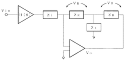
第1の実施の形態に係わる生体インピーダンス測定装置の構成について、図1に示すブロック図を参照して説明する。
【0011】
第1の実施の形態の生体インピーダンス測定装置は、測定手段1と、記憶部2と、マイコン3と、表示部4とを備える。
【0012】
測定手段1においては、生体5、外部基準器6又は内部基準器7についてのインピーダンスに基因する電圧を測定する。そして、この測定手段1は、定電圧(正弦波交流)発生器8、電圧/電流変換器9、内部基準器7、電極A10、電極B11、切替器12、増幅器13、フィルタ14及びA/D変換器(同期検波方式)15から成る。
【0013】
定電圧(正弦波交流)発生器8は、高周波(例えば、50kHz)の定電圧を発生し、電圧/電流変換器9に出力すると共に、正弦波発生のタイミング信号をA/D変換器(同期検波方式)15に出力する。電圧/電流変換器9は、定電圧(正弦波交流)発生器8から受けた定電圧を定電流に変換し、内部基準器7に出力する。
【0014】
内部基準器7は、環境等の温度変化の原因により、定電圧(正弦波交流)発生器8や電圧/電流変換器9からの定電流の変化がもたらすインピーダンスの影響を補正するための基準となるインピーダンスである。この内部基準器7は、従来の技術で引用したインピーダンス測定法(特許第2835656号公報参照)における複数の既知抵抗値の基準抵抗群にあたるものである。本件においては、この内部基準器7には、一つの既知基準抵抗を用いる。
【0015】
電極A10は、電圧/電流変換器9から内部基準器7を経た定電流を生体5又は外部基準器6に通電するための端子である。電極B11は、生体5又は外部基準器6に発生する電圧を検出するための端子である。
【0016】
切替器12は、定電流が内部基準器7に流れたことにより内部基準器7に発生する電圧と、定電流が2つの電極B11間の生体5又は外部基準器6に流れたことにより2つの電極B11間に発生する電圧との検出を切り替える。
【0017】
増幅器13は、切替器12を経た内部基準器7のインピーダンスに基因する電圧、又は生体5若しくは外部基準器6のインピーダンスに基因する電圧を増幅する。フィルタ14は、増幅器13で増幅された電圧のノイズ成分を除去する。
【0018】
A/D変換器(同期検波方式)15は、フィルタ14でノイズ成分が除去された電圧(アナログ)をデジタル変換すると共に、定電圧(正弦波交流)発生器8からの正弦波発生のタイミング信号に基づいて、内部基準器7又は生体5若しくは外部基準器6の抵抗成分に基因する電圧とリアクタンス成分に基因する電圧とに分離してマイコン3に出力する。なお、このA/D変換器(同期検波方式)15は、測定手段1の一部を成すと共に、測定手段1で測定されたインピーダンスに基因する電圧を、抵抗成分に基因する電圧とリアクタンス成分に基因する電圧とに分離する分離手段16をも兼ねる。
【0019】
記憶部2においては、演算式記憶手段17及び変動定数記憶手段18を有すると共に、各種演算の際の一時的な記憶その他の公知の如き記憶を行う。なお、記憶部2には、EEPROMを用いる。
【0020】
演算式記憶手段17は、測定手段1に生じるインピーダンス変動要因に基づく変動を表す変動変数と、実測によるインピーダンスの抵抗成分に基因する電圧及びリアクタンス成分に基因する電圧を表す実測電圧変数とに、生体5又は外部基準器6の真のインピーダンスの抵抗成分及びリアクタンス成分を表す真インピーダンス変数を対応させたインピーダンス演算式を予め記憶する。
【0021】
なお、インピーダンス演算式は、測定手段1に生じるインピーダンス変動要因に基づく変動を考慮した図2の測定手段1における回路モデルに基づいて導き出した数3の式である。図2の各部は、測定手段1に生じる位相変動成分をH(θ)、電圧/電流変換器9のインピーダンスをZi、内部基準器7のインピーダンスをZR、浮遊容量等によるインピーダンスをZS、生体5又は外部基準器6のインピーダンスをZB、内部基準器7と生体5(又は外部基準器6)とにかけて生ずる電圧をVO、内部基準器7のインピーダンス成分で生ずる電圧をVR、生体5又は外部基準器6のインピーダンス成分で生ずる電圧をVBで表す。
【0022】
この回路モデルによると、生体5又は外部基準器6のインピーダンスは、ZB=VB /(1−ZR/ZS)・ZR/VR=CVB/VRの式となる。ここでCは、スケールファクター及び位相に基づく変動を表す変動変数となる。そして、この式に、主にZSに起因するオフセット電圧に基づく変動を表す変動変数VOSを考慮すると共に、各変数を抵抗成分及びリアクタンス成分に分解する(ZBを生体5又は外部基準器6の真のインピーダンスの抵抗成分を表す真インピーダンス成分変数RBとリアクタンス成分を表す真インピーダンス成分変数XBとし、Cを抵抗成分のスケールファクター及び位相に基づく変動を表す変動変数CRとリアクタンス成分のスケールファクター及び位相に基づく変動を表す変動変数CXとし、VBを生体5又は外部基準器6の抵抗成分に基因する電圧を表す実測電圧変数VBRとリアクタンス成分に基因する電圧を表す実測電圧変数VBXとし、VRを内部基準器7の抵抗成分に基因する電圧を表す実測電圧変数VRRとリアクタンス成分に基因する電圧を表す実測電圧変数VRXとし、VOSを抵抗成分軸方向へのオフセット電圧に基づく変動を表す変動変数VOSRとリアクタンス成分軸方向に対するオフセット電圧に基づく変動を表す変動変数VOSXとする。)ことで数3の式が導かれる。
【数3】
この数3の式におけるスケールファクター及び位相に基づく変動を表す変動変数CR、CX、オフセット電圧に基づく変動を表す変動変数VOSR、VOSXは、測定手段1に生じるインピーダンス変動要因に基づく変動を表す変動変数に該当する。
【0024】
図3は、インピーダンスの抵抗成分及びリアクタンス成分の関係を座標に表す図である。縦軸Xはリアクタンス成分を、横軸Rは抵抗成分を、点Zはインピーダンスを、座標交点Oは零地点を、偏角θは位相差を表す。スケールファクター及び位相に基づく変動を示す変動変数CR、CXは、線分OZ方向の変動及び偏角θの変動についての変数を表し、オフセット電圧に基づく変動を表す変動変数VOSR、VOSXは、座標交点Oの変動についての変数を表すものである。
【0025】
変動定数記憶手段18は、後述する変動定数演算手段19で演算される変動定数を記憶する。
【0026】
マイコン3においては、変動定数演算手段19及び生体インピーダンス演算手段20を有すると共に、定電圧(正弦波交流)発生器8からの高周波の定電圧の発生の制御その他の公知の如き制御を行う。
【0027】
変動定数演算手段19は、内部基準器7及び外部基準器6の測定によってA/D変換器(同期検波方式)15から出力された抵抗成分に基因する電圧とリアクタンス成分に基因する電圧と、測定手段1で測定される外部基準器6のインピーダンスの既知の抵抗成分及びリアクタンス成分とを、記憶手段に予め記憶されるインピーダンス演算式(数3の式)に代入して変動変数の定数である変動定数を演算し、変動定数記憶手段18に出力する。
【0028】
生体インピーダンス演算手段20は、変動定数記憶手段18で記憶される変動定数と、測定手段1で測定される生体5のインピーダンスの抵抗成分に基因する電圧及びリアクタンス成分に基因する電圧とを、演算式記憶手段17に予め記憶されるインピーダンス演算式(数3の式)に代入し、生体5の真のインピーダンスの抵抗成分及びリアクタンス成分を演算する。
【0029】
表示部4は、生体インピーダンス演算手段20で演算された結果を表示する。
【0030】
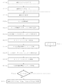
第1の実施の形態に係わる生体インピーダンス測定装置の使用及び動作の流れについて、図4に示すフローチャートを参照して説明する。
【0031】
まず、図1に示すように、生体インピーダンスの測定範囲の下限に該当する既知のインピーダンス(例えば、R=100Ω、X=0Ω)である外部基準器6を電極A10及び電極B11に接続する(ステップ1)。
【0032】
続いて、マイコン3からの制御により定電圧(正弦波交流)発生器8から高周波(例えば、50kHz)の定電圧を発生し、電圧/電流変換器9でこの高周波の定電圧を定電流に変換し、内部基準器7へと出力する。また、定電圧(正弦波交流)発生器8からは正弦波発生のタイミング信号をA/D変換器(同期検波方式)15にも出力する。次いで、切替器12を既知のインピーダンス(例えば、R=800Ω、X=0Ω)である内部基準器7側と接続し、この内部基準器7に生じる電圧を検出し、この電圧を増幅器13で増幅し、この増幅された電圧のノイズ成分をフィルタ14で除去する。次いで、A/D変換器(同期検波方式)15で、この電圧(アナログ)をデジタル変換すると共に、定電圧(正弦波交流)発生器8からの正弦波発生のタイミング信号に基づいて、内部基準器7の抵抗成分に基因する電圧とリアクタンス成分に基因する電圧とに分離してマイコン3に出力する。次いで、マイコン3で、この分離された内部基準器7の抵抗成分に基因する電圧とリアクタンス成分に基因する電圧とを記憶部2に出力する。次いで、記憶部2で、この内部基準器7の抵抗成分に基因する電圧とリアクタンス成分に基因する電圧とを一時的に記憶する(ステップ2)。
【0033】
続いて、切替器12を内部基準器7側から外部基準器6側へと接続を切替え、この外部基準器6に生じる電圧を検出し、増幅器13でこの電圧を増幅し、フィルタ14でこの増幅された電圧のノイズ成分を除去する。次いで、A/D変換器(同期検波方式)15で、この電圧(アナログ)をデジタル変換すると共に、定電圧(正弦波交流)発生器8からの正弦波発生のタイミング信号に基づいて、外部基準器6の抵抗成分に基因する電圧とリアクタンス成分に基因する電圧とに分離してマイコン3に出力する。次いで、マイコン3で、この分離された外部基準器6の抵抗成分に基因する電圧とリアクタンス成分に基因する電圧とを記憶部2に出力する。次いで、記憶部2で、この外部基準器6の抵抗成分に基因する電圧とリアクタンス成分に基因する電圧とを一時的に記憶する(ステップ3)。
【0034】
続いて、電極A10及び電極B11への接続を、生体インピーダンスの測定範囲の下限に該当する既知のインピーダンス(例えば、R=100Ω、X=0Ω)である外部基準器6から、生体インピーダンスの測定範囲の上限に該当する既知のインピーダンス(例えば、R=800Ω、X=0Ω)である外部基準器6に替える(ステップ4)。
【0035】
続いて、ステップ2と同様の処理を行い、内部基準器7の抵抗成分に基因する電圧とリアクタンス成分に基因する電圧とを記憶部2に一時的に記憶する(ステップ5)。
【0036】
続いて、ステップ3と同様の処理を行い、生体インピーダンスの測定範囲の上限に該当する既知のインピーダンス(例えば、R=800Ω、X=0Ω)である外部基準器6の抵抗成分に基因する電圧とリアクタンス成分に基因する電圧とを記憶部2に一時的に記憶する(ステップ6)。
【0037】
続いて、変動定数演算手段19において、まず、ステップ3で記憶部2に一時的に記憶されている抵抗成分に基因する電圧及びリアクタンス成分に基因する電圧と、ステップ1で電極A10及び電極B11に接続された外部基準器6のインピーダンスの抵抗成分及びリアクタンス成分を数3の式に代入して第1式とする。より具体的に詳述すると、数3の式の実測電圧変数VRRに、外部基準器6(R=100Ω、X=0Ω)の接続時における内部基準器(R=800Ω、X=0Ω)7の抵抗成分(R=800Ω)に基因する電圧を代入し、実測電圧変数VRXに、外部基準器6(R=100Ω、X=0Ω)の接続時における内部基準器(R=800Ω、X=0Ω)7のリアクタンス成分(X=0Ω)に基因する電圧を代入し、実測電圧変数VBRに、外部基準器6(R=100Ω、X=0Ω)の接続時におけるこの外部基準器6の抵抗成分(R=100Ω)に基因する電圧を代入し、実測電圧変数VBXに、外部基準器6(R=100Ω、X=0Ω)の接続時におけるこの外部基準器6のリアクタンス成分(X=0Ω)に基因する電圧を代入し、真インピーダンス成分変数RBに、外部基準器6(R=100Ω、X=0Ω)の接続時におけるこの外部基準器6の抵抗成分(R=100Ω)を代入し、真インピーダンス成分変数XBに、外部基準器6(R=100Ω、X=0Ω)の接続時におけるこの外部基準器6のリアクタンス成分(X=0Ω)を代入し、第1式とする。
【0038】
次に、ステップ6で記憶部2に一時的に記憶されている抵抗成分に基因する電圧及びリアクタンス成分に基因する電圧と、ステップ4で電極A10及び電極B11に接続された外部基準器6のインピーダンスの抵抗成分及びリアクタンス成分を数3の式に代入して第2式とする。より具体的に詳述すると、数3の式の実測電圧変数VRRに、外部基準器6(R=800Ω、X=0Ω)の接続時における内部基準器(R=800Ω、X=0Ω)7の抵抗成分(R=800Ω)に基因する電圧を代入し、実測電圧変数VRXに、外部基準器6(R=800Ω、X=0Ω)の接続時における内部基準器(R=800Ω、X=0Ω)7のリアクタンス成分(X=0Ω)に基因する電圧を代入し、実測電圧変数VBRに、外部基準器6(R=800Ω、X=0Ω)の接続時におけるこの外部基準器6の抵抗成分(R=800Ω)に基因する電圧を代入し、実測電圧変数VBXに、外部基準器6(R=800Ω、X=0Ω)の接続時におけるこの外部基準器6のリアクタンス成分(X=0Ω)に基因する電圧を代入し、真インピーダンス成分変数RBに、外部基準器6(R=800Ω、X=0Ω)の接続時におけるこの外部基準器6の抵抗成分(R=800Ω)を代入し、真インピーダンス成分変数XBに、外部基準器6(R=800Ω、X=0Ω)の接続時におけるこの外部基準器6のリアクタンス成分(X=0Ω)を代入し、第2式とする。
【0039】
そして、第1式と第2式とを連立方程式で解くことにより、変動変数CR、CXのそれぞれの定数(変動定数)、実測電圧変数VOSR、VOSXのそれぞれの定数(変動定数)を求める(ステップ7)。
【0040】
続いて、変動定数記憶手段18でこれらの求められた変動定数を以後継続的に記憶する(ステップ8)。なお、記憶部2に一時的に記憶されたこれまでの各抵抗成分に基因する電圧と各リアクタンス成分に基因する電圧とは、以後記憶を消去しても良い。
【0041】
続いて、図1に示すように、生体5の一部位を電極A10及び電極B11に接続する(ステップ9)。
【0042】
続いて、ステップ2と同様の処理を行い、内部基準器7の抵抗成分に基因する電圧とリアクタンス成分に基因する電圧とを記憶部2に一時的に記憶する(ステップ10)。
【0043】
続いて、切替器12を内部基準器7側から生体5側へと接続を切替え、この生体5に生じる電圧を検出し、この電圧を増幅器13で増幅し、この増幅された電圧のノイズ成分をフィルタ14で除去する。次いで、A/D変換器(同期検波方式)15で、この電圧(アナログ)をデジタル変換すると共に、定電圧(正弦波交流)発生器8からの正弦波発生のタイミング信号に基づいて、生体5の抵抗成分に基因する電圧とリアクタンス成分に基因する電圧とに分離してマイコン3の生体インピーダンス演算手段20に出力する(ステップ11)。
【0044】
続いて、生体インピーダンス演算手段20において、演算式記憶手段17に記憶される数3の式に、この出力された生体5の抵抗成分に基因する電圧及びリアクタンス成分に基因する電圧と、変動定数記憶手段18に記憶される変動定数と代入して、生体5の真のインピーダンスの抵抗成分RBと生体5の真のインピーダンスのリアクタンス成分XBとを演算する。より具体的に詳述すると、数3の式の実測電圧変数VBRに、A/D変換器(同期検波方式)15で分離された生体5の抵抗成分に基因する電圧を代入し、実測電圧変数VBXに、生体5のリアクタンス成分に基因する電圧を代入し、実測電圧変数VRRに、ステップ11で記憶部2に一時的に記憶される内部基準器7の抵抗成分に基因する電圧を代入し、実測電圧変数VRXに、内部基準器7のリアクタンス成分に基因する電圧を代入し、変動変数CR、CXに、ステップ8で変動定数記憶手段18に記憶される各変動定数を代入し、変動変数VOSR、VOSXに、オフセット電圧を補正する各変動定数を代入しすることにより、生体5の真のインピーダンスの抵抗成分RBと生体5の真のインピーダンスのリアクタンス成分XBとを演算して出力する(ステップ12)。
【0045】
続いて、生体インピーダンス演算手段20から出力された生体5の真のインピーダンスの抵抗成分RBと生体5の真のインピーダンスのリアクタンス成分XBとを測定結果として表示部4で表示する(ステップ13)ことにより、一連の処理手順が終了する。
【0046】
次に、第2の実施の形態として、ソフト的処理によって、実測される生体のインピーダンスを抵抗成分とリアクタンス成分とに分離して生体の真のインピーダンスを求める態様について詳述する。
【0047】
第2の実施の形態に係わる生体インピーダンス測定装置の構成について、図5に示すブロック図を参照して説明する。
【0048】
第2の実施の形態の生体インピーダンス測定装置は、測定手段21と、記憶部2と、マイコン23と、表示部4とを備える。
【0049】
測定手段21においては、生体5、外部基準器6又は内部基準器7についてのインピーダンスに基因する電圧を測定する。そして、この測定手段21は、定電圧(正弦波交流)発生器24、電圧/電流変換器9、内部基準器7、電極A10、電極B11、切替器12、増幅器13、フィルタ14及びA/D変換器25から成る。なお、電圧/電流変換器9、内部基準器7、電極A10、電極B11、切替器12、増幅器13及びフィルタ14については、第1の実施の形態と同様なので詳述を省略し、定電圧(正弦波交流)発生器24とA/D変換器25とについて詳述する。
【0050】
定電圧(正弦波交流)発生器24は、高周波(例えば、50kHz)の定電圧を発生し、電圧/電流変換器9に出力する。(第1の実施の形態のように、正弦波発生のタイミング信号のA/D変換器への出力を行わない。)
【0051】
A/D変換器25は、フィルタ14でノイズ成分が除去された電圧(アナログ)をデジタル変換して、マイコン23に出力する。(第1の実施の形態のように、インピーダンスに基因する電圧を抵抗成分に基因する電圧とリアクタンス成分に基因する電圧とに分離する分離手段を兼ねない。)
【0052】
記憶部2(演算式記憶手段17及び変動定数記憶手段18)は、第1の実施の形態と同様なので詳述を省略する。
【0053】
マイコン23においては、分離手段26、変動定数演算手段19及び生体インピーダンス演算手段20を有すると共に、定電圧(正弦波交流)発生器24からの高周波の定電圧の発生の制御その他の公知の如き制御を行う。
【0054】
分離手段26は、A/D変換器25から出力されたインピーダンスに基因する電圧と、定電圧(正弦波交流)発生器24から発生される正弦波の周期と同じ又は90゜進む周期を時分割した振幅とに基づいて、内部基準器7又は生体5若しくは外部基準器6の実測による抵抗成分に基因する電圧とリアクタンス成分に基因する電圧とを演算する。
【0055】
変動定数演算手段19は、内部基準器7及び外部基準器6の測定によって分離手段26で演算により分離された抵抗成分に基因する電圧とリアクタンス成分に基因する電圧と、測定手段21で測定される外部基準器6のインピーダンスの既知の抵抗成分及びリアクタンス成分とに基づいて、演算式記憶手段17に予め記憶されるインピーダンス演算式(数3の式)から変動変数の定数である変動定数を演算する。
【0056】
生体インピーダンス演算手段20は、変動定数記憶手段18で記憶される変動定数と、測定手段21で測定され、分離手段26で分離される生体5のインピーダンスの抵抗成分に基因する電圧及びリアクタンス成分に基因する電圧とを、演算式記憶手段17に予め記憶されるインピーダンス演算式(数3の式)に代入し、生体5の真のインピーダンスの抵抗成分及びリアクタンス成分を演算する。
【0057】
表示部4は、生体インピーダンス演算手段20で演算された結果を表示する。
【0058】
第2の実施の形態に係わる生体インピーダンス測定装置の使用及び動作の流れについて、図4に示すフローチャートを参照して説明する。
【0059】
まず、図5に示すように、生体インピーダンスの測定範囲の下限に該当する既知のインピーダンス(例えば、R=100Ω、X=0Ω)である外部基準器6を電極A10及び電極B11に接続する(ステップ1)。
【0060】
続いて、マイコン23からの制御により定電圧(正弦波交流)発生器24から高周波(例えば、50kHz)の定電圧を発生し、電圧/電流変換器9でこの高周波の定電圧を定電流に変換し、内部基準器7へと出力する。次いで、切替器12を既知のインピーダンス(例えば、R=800Ω、X=0Ω)である内部基準器7側と接続し、この内部基準器7に生じる電圧を検出し、この電圧を増幅器13で増幅し、この増幅された電圧のノイズ成分をフィルタ14で除去し、この除去された電圧(アナログ)をA/D変換器25でデジタル信号に変換してマイコン23内の分離手段26に出力する。
【0061】
次いで、マイコン23内の分離手段26において、図6のフローチャートに示す処理を行い、内部基準器7の実測によるインピーダンスの抵抗成分に基因する電圧とリアクタンス成分に基因する電圧とを演算する(ステップ2)。
【0062】
このステップ2においての図6での処理をより具体的に詳述する。分離手段26におけるR成分電圧及びX成分電圧の各積算バッファをクリア(ステップ21)ておき、分離手段26における積算カウンタをn=0(ステップ22)とし、割り込み発生状態(ステップ23)とした上で、まず、上述したA/D変換器25が実行されて(ステップ24)、そのA/D変換器25から出力されたデジタル信号であるインピーダンスに基因する電圧(V(t))を取り込む(ステップ25)。次に、定電圧(正弦波交流)発生器24から発生される正弦波の周期と同じ周期を時分割した振幅(sinθ1)をマイコン23内のROMテーブルから読み込む(ステップ26)。次に、取り込んだ内部基準器7の実測によるインピーダンスに基因する電圧(V(t))と、マイコン23内のROMテーブルから読み込んだ定電圧(正弦波交流)発生器24から発生される正弦波の周期と同じ周期を時分割した振幅(sinθ1)を乗算し(ステップ27)、R成分電圧積算バッファに加算する(ステップ28)。次に、定電圧(正弦波交流)発生器24から発生される正弦波の周期より90゜進む周期を時分割した振幅(cosθ1)をマイコン23内のROMテーブルから読み込む(ステップ29)。次に、取り込んだ内部基準器7の実測によるインピーダンスに基因する電圧(V(t))と、マイコン23内のROMテーブルから読み込んだ定電圧(正弦波交流)発生器24から発生される正弦波の周期より90゜進む周期を時分割した振幅(cosθ1)を乗算し(ステップ30)、X成分電圧積算バッファに加算する(ステップ31)。次に、積算カウンタがn<32であれば(ステップ32でYES)、積算カウンタをn=n+1として(ステップ33)、ステップ23に戻り処理を繰り返す。なお、その際におけるステップ26及びステップ29では、時分割した振幅sinθi、cosθiのiが順次繰り上がったものが読み込まれる。一方、積算カウンタがn<32でなければ(ステップ32でNO)、R成分電圧及びX成分電圧積算バッファに積算された実測電圧変数VRR及びVRXを記憶部2に一時的に記憶する(ステップ34)。
【0063】
続いて、切替器12を内部基準器7側から外部基準器6(R=100Ω、X=0Ω)側へと接続を切替え、この外部基準器6に生じる電圧を検出し、増幅器13でこの電圧を増幅し、フィルタ14でこの増幅された電圧のノイズ成分を除去し、この除去された電圧(アナログ)をA/D変換器25でデジタル信号に変換してマイコン23内の分離手段26に出力する。
【0064】
次いで、マイコン23内の分離手段26において、図6のフローチャートに示す処理を行い、外部基準器6の実測によるインピーダンスの抵抗成分に基因する電圧とリアクタンス成分に基因する電圧とを演算する(ステップ3)。
【0065】
このステップ3における図6での処理をより具体的に詳述する。分離手段26におけるR成分電圧及びX成分電圧の各積算バッファをクリア(ステップ21)ておき、分離手段26における積算カウンタをn=0(ステップ22)とし、割り込み発生状態(ステップ23)とした上で、まず、上述したA/D変換器25が実行されて(ステップ24)、そのA/D変換器25から出力されたデジタル信号であるインピーダンスに基因する電圧(V(t))を取り込む(ステップ25)。次に、定電圧(正弦波交流)発生器24から発生される正弦波の周期と同じ周期を時分割した振幅(sinθ1)をマイコン23内のROMテーブルから読み込む(ステップ26)。次に、取り込んだ外部基準器6の実測によるインピーダンスに基因する電圧(V(t))と、マイコン23内のROMテーブルから読み込んだ定電圧(正弦波交流)発生器24から発生される正弦波の周期と同じ周期を時分割した振幅(sinθ1)を乗算し(ステップ27)、R成分電圧積算バッファに加算する(ステップ28)。次に、定電圧(正弦波交流)発生器24から発生される正弦波の周期より90゜進む周期を時分割した振幅(cosθ1)をマイコン23内のROMテーブルから読み込む(ステップ29)。次に、取り込んだ外部基準器6の実測によるインピーダンスに基因する電圧(V(t))と、マイコン23内のROMテーブルから読み込んだ定電圧(正弦波交流)発生器24から発生される正弦波の周期より90゜進む周期を時分割した振幅(cosθ1)を乗算し(ステップ30)、X成分電圧積算バッファに加算する(ステップ31)。次に、積算カウンタがn<32であれば(ステップ32でYES)、積算カウンタをn=n+1として(ステップ33)、ステップ23に戻り処理を繰り返す。なお、その際におけるステップ26及びステップ29では、時分割した振幅sinθi、cosθiのiが順次繰り上がったものが読み込まれる。一方、積算カウンタがn<32でなければ(ステップ32でNO)、R成分電圧及びX成分電圧積算バッファに積算された実測電圧変数VBR及びVBXを記憶部2に一時的に記憶する(ステップ34)。
【0066】
続いて、電極A10及び電極B11への接続を、生体インピーダンスの測定範囲の下限に該当する既知のインピーダンス(例えば、R=100Ω、X=0Ω)である外部基準器6から、生体インピーダンスの測定範囲の上限に該当する既知のインピーダンス(例えば、R=800Ω、X=0Ω)である外部基準器6に替える(ステップ4)。
【0067】
続いて、ステップ2と同様の処理を行い、内部基準器7の抵抗成分に基因する電圧とリアクタンス成分に基因する電圧とを記憶部2に一時的に記憶する(ステップ5)。
【0068】
続いて、ステップ3と同様の処理を行い、生体インピーダンスの測定範囲の上限に該当する既知のインピーダンス(例えば、R=800Ω、X=0Ω)である外部基準器6の抵抗成分に基因する電圧とリアクタンス成分に基因する電圧とを記憶部2に一時的に記憶する(ステップ6)。
【0069】
続いて、ステップ7乃至ステップ9においては、第1の実施の形態における処理と同様であり、詳述を省略する。
【0070】
続いて、ステップ2と同様の処理を行い、内部基準器7の抵抗成分に基因する電圧とリアクタンス成分に基因する電圧とを記憶部2に一時的に記憶する(ステップ10)。
【0071】
続いて、切替器を内部基準器7側から生体5側へと接続を切替え、この生体5に生じる電圧を検出し、この電圧を増幅器13で増幅し、この増幅された電圧のノイズ成分をフィルタ14で除去し、この除去された電圧(アナログ)をA/D変換器25でデジタル信号に変換してマイコン23内の分離手段26に出力する。
【0072】
次いで、マイコン23内の分離手段26において、図6のフローチャートに示すような処理を行い、生体5の実測による抵抗成分に基因する電圧とリアクタンス成分に基因する電圧とを演算する(ステップ11)。
【0073】
このステップ11における図6での処理をより具体的に詳述する。分離手段26におけるR成分電圧及びX成分電圧の各積算バッファをクリア(ステップ21)ておき、分離手段26における積算カウンタをn=0(ステップ22)とし、割り込み発生状態(ステップ23)とした上で、まず、上述したA/D変換器25が実行されて(ステップ24)、そのA/D変換器25から出力されたデジタル信号であるインピーダンスに基因する電圧(V(t))を取り込む(ステップ25)。次に、定電圧(正弦波交流)発生器24から発生される正弦波の周期と同じ周期を時分割した振幅(sinθ1)をマイコン23内のROMテーブルから読み込む(ステップ26)。次に、取り込んだ生体5の実測によるインピーダンスに基因する電圧(V(t))と、マイコン23内のROMテーブルから読み込んだ定電圧(正弦波交流)発生器24から発生される正弦波の周期と同じ周期を時分割した振幅(sinθ1)を乗算し(ステップ27)、R成分電圧積算バッファに加算する(ステップ28)。次に、定電圧(正弦波交流)発生器24から発生される正弦波の周期より90゜進む周期を時分割した振幅(cosθ1)をマイコン23内のROMテーブルから読み込む(ステップ29)。次に、取り込んだ生体5の実測によるインピーダンスに基因する電圧(V(t))と、マイコン23内のROMテーブルから読み込んだ定電圧(正弦波交流)発生器24から発生される正弦波の周期より90゜進む周期を時分割した振幅(cosθ1)を乗算し(ステップ30)、X成分電圧積算バッファに加算する(ステップ31)。次に、積算カウンタがn<32であれば(ステップ32でYES)、積算カウンタをn=n+1として(ステップ33)、ステップ23に戻り処理を繰り返す。なお、その際におけるステップ26及びステップ29では、時分割した振幅sinθi、cosθiのiが順次繰り上がったものが読み込まれる。一方、積算カウンタがn<32でなければ(ステップ32でNO)、R成分電圧及びX成分電圧積算バッファに積算された実測電圧変数VBR及びVBXを生体インピーダンス演算手段20に出力する(ステップ34)。
【0074】
続いて、生体インピーダンス演算手段20において、演算式記憶手段17に記憶される数3の式に、この出力された生体5の抵抗成分に基因する電圧及びリアクタンス成分に基因する電圧と、変動定数記憶手段18に記憶される変動定数と代入して、生体5の真のインピーダンスの抵抗成分RBと生体5の真のインピーダンスのリアクタンス成分XBとを演算する。より具体的に詳述すると、数3の式の実測電圧変数VBRに、分離手段26で分離された生体5の抵抗成分に基因する電圧を代入し、実測電圧変数VBXに、生体5のリアクタンス成分に基因する電圧を代入し、実測電圧変数VRRに、ステップ11で記憶部2に一時的に記憶される内部基準器7の抵抗成分に基因する電圧を代入し、実測電圧変数VRXに、内部基準器7のリアクタンス成分に基因する電圧を代入し、変動変数CR、CXに、ステップ8で変動定数記憶手段18に記憶される各変動定数を代入し、変動変数VOSR、VOSXに、オフセット電圧を補正する各変動定数を代入しすることにより、生体5の真のインピーダンスの抵抗成分RBと生体5の真のインピーダンスのリアクタンス成分XBとを演算して出力する(ステップ12)。
【0075】
続いて、生体インピーダンス演算手段20から出力された生体5の真のインピーダンスの抵抗成分RBと生体5の真のインピーダンスのリアクタンス成分XBとを測定結果として表示部4で表示する(ステップ13)ことにより、一連の処理手順が終了する。
【0076】
上述したように、本発明の生体インピーダンス測定装置は、測定手段により測定対象(生体、外部基準器、内部基準器)のインピーダンスに基因する電圧を測定し、ハード的又はソフト的な手段に基づいた分離手段により抵抗成分に基因する電圧とリアクタンス成分に基因する電圧とに分離する。これにより、インピーダンス変動要因と密接関係にある抵抗成分とリアクタンス成分とに分離できる。そして、変動定数演算手段によりこれらの抵抗成分に基因する電圧及びリアクタンス成分に基因する電圧と、外部基準器のインピーダンスの抵抗成分及びリアクタンス成分とを、演算式記憶手段に予め記憶されるインピーダンス変動が考慮されたインピーダンス演算式(数3の式)に代入し、インピーダンス変動要因に基づく変動を表す変動変数の定数である変動定数を演算する。これにより、インピーダンス変動要因に基づく数値化した変動を求めることができる。更に、生体インピーダンス演算手段により変動定数と、測定された生体のインピーダンスとを、演算式記憶手段に予め記憶されるインピーダンス演算式(数3の式)に新たに代入し、生体の真のインピーダンスの抵抗成分及びリアクタンス成分を演算する。これにより、インピーダンス変動要因による変動分が補正された正確なデータを得ることができる。
【0077】
なお、上述した実施の形態においては、生体インピーダンスの測定範囲の下限に該当する既知のインピーダンス(例えば、R=100Ω、X=0Ω)である外部基準器と、生体インピーダンスの測定範囲の上限に該当する既知のインピーダンス(例えば、R=800Ω、X=0Ω)である外部基準器とを測定したが、同一の外部基準器であっても実施可能である。
【0078】
また、測定手段には、内部基準器を有するものとして説明したが、内部基準器は有せずとも実施可能である。本件形態の説明の如き内部基準器を有する場合には、従来の技術で引用したインピーダンス測定法(特許第2835656号公報参照)の効果、すなわち、定電流源の環境変化による変動に影響されないといったことも享受できる。
【0079】
更に、ステップ12において、生体の真のインピーダンスの抵抗成分RBと生体の真のインピーダンスのリアクタンス成分XBとを演算して出力したが、抵抗成分RBとリアクタンス成分XBとから生体の真のインピーダンスZBとして出力してもよい。
【0080】
更に、図2の回路モデルから導かれる数3の式を用いたが、数4、数5、数6又は数7の式を導いて用いても同様に実施可能である。
【数4】
【0081】
【発明の効果】
以上説明したように、本発明の生体インピーダンス測定装置は、測定手段により測定対象(生体、外部基準器、内部基準器)のインピーダンスに基因する電圧を測定し、分離手段により抵抗成分に基因する電圧とリアクタンス成分に基因する電圧とに分離し、変動定数演算手段によりこれらの抵抗成分に基因する電圧及びリアクタンス成分に基因する電圧と、外部基準器のインピーダンスの抵抗成分及びリアクタンス成分とを、演算式記憶手段に予め記憶されるインピーダンス変動が考慮されたインピーダンス演算式(数3の式)に代入し、インピーダンス変動要因に基づく変動を表す変動変数の定数である変動定数を演算し、生体インピーダンス演算手段により変動定数と、測定された生体のインピーダンスとを、演算式記憶手段に予め記憶されるインピーダンス演算式(数3の式)に新たに代入し、生体の真のインピーダンスの抵抗成分及びリアクタンス成分を演算する。これにより、インピーダンス変動要因と密接関係にある抵抗成分とリアクタンス成分とに分離して、インピーダンス変動要因に基づく数値化(定数化)した変動を求め、インピーダンス変動要因による変動分が補正された正確な真の生体インピーダンス(真の生体の抵抗成分、真の生体のリアクタンス成分)を得ることができる。
【図面の簡単な説明】
【図1】生体インピーダンス測定装置(第1の実施の形態)の構成を示すブロック図である。
【図2】測定手段における回路モデルである。
【図3】インピーダンスの抵抗成分及びリアクタンス成分の関係を示す座標図である。
【図4】生体インピーダンス測定装置の使用及び動作の流れを示すフローチャートである。
【図5】生体インピーダンス測定装置(第2の実施の形態)の構成を示すブロック図である。
【図6】分離手段26(第2の実施の形態)での処理の流れを示すフローチャートである。
【符号の説明】
1、21 測定手段
2、22 記憶部
3、23 マイコン
4 表示部
5 生体
6 外部基準器
7 内部基準器
8、24 定電圧(正弦波交流)発生器
9 電圧/電流変換器
10 電極A
11 電極B
12 切替器
13 増幅器
14 フィルタ
15 A/D変換器(同期検波方式)
16、26 分離手段
17 演算式記憶手段
18 変動定数記憶手段
19 変動定数演算手段
20 生体インピーダンス演算手段
25 A/D変換器[0001]
BACKGROUND OF THE INVENTION
The present invention relates to a bioimpedance measuring apparatus that separates a measured impedance of a living body into a resistance component and a reactance component to obtain a true impedance of the living body.
[0002]
[Prior art]
A reference resistance group having a plurality of known resistance values that can appropriately divide a measured bioimpedance value is connected in series to a living body in a measurement current path of the bioelectrical impedance, and a voltage drop value due to the plurality of resistance values of the reference resistance group and the living body are connected. Measure the voltage drop value due to, determine the correlation equation between the resistance value and the corresponding measurement voltage value, and use the measured voltage value and correlation equation of the living body obtained by measurement An impedance measurement method for obtaining the above (refer to Japanese Patent No. 2835656) is disclosed.
[0003]
[Problems to be solved by the invention]
However, the conventional impedance measurement method described above includes impedance variation factors in a sine wave oscillator, a voltage-current converter, a current path, and the like for generating a constant current. For this reason, the bioimpedance determined by measurement is not accurate.
[0004]
Therefore, an object of the present invention is to solve the conventional problems as described above, and an object of the present invention is to provide an accurate bioimpedance measuring apparatus that is less affected by fluctuations due to impedance fluctuation factors.
[0005]
[Means for Solving the Problems]
In order to achieve the above object, a bioimpedance measurement apparatus according to the present invention comprises a measuring means for measuring a voltage caused by impedance of a living body, an external reference device, or an internal reference device, and the measurement Separating means for separating the voltage caused by the impedance measured by the means into a voltage caused by the resistance component and a voltage caused by the reactance component; a variable variable representing a fluctuation based on the impedance fluctuation factor generated in the measuring means; Impedances that correspond to the actual impedance variable that represents the resistance component and reactance component of the living body or external reference device to the actual measurement voltage variable that represents the voltage caused by the resistance component and reactance component of the measured impedance An arithmetic expression storage means for storing an arithmetic expression in advance, The voltage caused by the resistance component and the voltage caused by the reactance component separated by the separation means corresponding to the voltage caused by the impedance of the external reference device measured by the measurement means, and the external reference measured by the measurement means Substituting the resistance component and the reactance component of the impedance of the capacitor into the impedance calculation formula stored in advance in the calculation formula storage means, and the fluctuation constant calculation means for calculating the fluctuation constant that is the constant of the fluctuation variable, and the fluctuation constant calculation A variable constant storage means for storing the fluctuation constant calculated by the means; a fluctuation constant stored by the variable constant storage means; and a voltage based on the impedance of the living body measured by the measurement means. Substituting into the impedance calculation formula stored in advance in the means to calculate the resistance component and reactance component of the true impedance of the living body A bioelectrical impedance computation means that, characterized in that it comprises a.
[0006]
Further, the variation constant calculating means includes each voltage caused by each resistance component separated by the separating means corresponding to each voltage caused by each impedance of a plurality of different external reference devices measured by the measuring means, and Impedance calculation formulas stored in advance in the calculation formula storage means for each voltage caused by each reactance component, and each resistance component and each reactance component of each impedance of a plurality of different external reference devices measured by the measurement means And a fluctuation constant that is a constant of the fluctuation variable is calculated.
[0007]
In addition, the impedance calculation formula includes a variable variable representing a variation based on the scale factor and phase of the resistance component as a variable variable.R, A variation variable representing variation based on the scale factor and phase of the reactance component is represented by CX, V f is a variation variable representing variation based on the offset voltage in the axial direction of the resistance componentOSRAnd a variable representing the fluctuation based on the offset voltage in the reactance component axial direction is VOSXAs an actually measured voltage variable, an actually measured voltage variable representing a voltage caused by a resistance component of impedance measured by a living body or an external reference device is VBR, The measured voltage variable representing the voltage due to the reactance component is VBX, The measured voltage variable representing the voltage caused by the resistance component of the impedance measured by the internal reference device is VRRAnd the measured voltage variable representing the voltage due to the reactance component is VRXAnd the true impedance component variable representing the resistance component of the true impedance of the living body or the external reference device as RBAnd the true impedance component variable representing the reactance component XBage,
[Expression 2]
[0008]
DETAILED DESCRIPTION OF THE INVENTION
Hereinafter, embodiments of the present invention will be described with reference to the drawings.
[0009]
First, as a first embodiment, an aspect in which the real impedance of a living body is obtained by separating the actually measured impedance of the living body into a resistance component and a reactance component by hardware processing will be described in detail.
[0010]
The configuration of the bioimpedance measurement apparatus according to the first embodiment will be described with reference to the block diagram shown in FIG.
[0011]
The bioimpedance measurement apparatus according to the first embodiment includes a
[0012]
In the measuring means 1, the voltage caused by the impedance of the
[0013]
The constant voltage (sine wave alternating current)
[0014]
The
[0015]
The electrode A <b> 10 is a terminal for passing a constant current from the voltage /
[0016]
Switcher 12Is a voltage generated in the
[0017]
The
[0018]
The A / D converter (synchronous detection method) 15 digitally converts the voltage (analog) from which the noise component has been removed by the
[0019]
The
[0020]
The arithmetic expression storage means 17 includes a variable variable representing a fluctuation based on an impedance fluctuation factor generated in the measurement means 1, a voltage caused by a resistance component of impedance measured actually, and a measured voltage variable representing a voltage caused by a reactance component. 5 or an
[0021]
The impedance calculation formula is a formula of Formula 3 derived based on the circuit model in the
[0022]
According to this circuit model, the impedance of the living
[Equation 3]
A variation variable C representing a variation based on the scale factor and phase in the equation (3)R, CX, Variation variable V representing variation based on offset voltageOSR, VOSXCorresponds to a variation variable representing a variation based on an impedance variation factor generated in the measuring means 1.
[0024]
FIG. 3 is a diagram illustrating the relationship between the resistance component and reactance component of the impedance in coordinates. The vertical axis X represents the reactance component, the horizontal axis R represents the resistance component, the point Z represents the impedance, the coordinate intersection O represents the zero point, and the declination θ represents the phase difference. Variation variable C indicating variation based on scale factor and phaseR, CXRepresents a variable about the fluctuation in the line segment OZ direction and the fluctuation of the deflection angle θ, and a fluctuation variable V representing a fluctuation based on the offset voltage.OSR, VOSXRepresents a variable about the change of the coordinate intersection point O.
[0025]
The fluctuation constant storage means 18 stores the fluctuation constant calculated by the fluctuation constant calculation means 19 described later.
[0026]
The
[0027]
The fluctuation constant calculating means 19 measures the voltage caused by the resistance component and the voltage caused by the reactance component, which are output from the A / D converter (synchronous detection method) 15 by the measurement of the
[0028]
The bioelectrical impedance calculating means 20 calculates the fluctuation constant stored in the fluctuation constant storage means 18, the voltage caused by the resistance component of the impedance of the living
[0029]
The
[0030]
The flow of use and operation of the bioimpedance measurement apparatus according to the first embodiment will be described with reference to the flowchart shown in FIG.
[0031]
First, as shown in FIG. 1, an
[0032]
Subsequently, a constant voltage (sine wave alternating current)
[0033]
Subsequently, the connection of the
[0034]
Subsequently, the connection to the electrode A10 and the electrode B11 is connected to the bioimpedance measurement range from the
[0035]
Subsequently, the same processing as in
[0036]
Subsequently, the same processing as in
[0037]
Subsequently, in the variation constant calculating means 19, first, the voltage caused by the resistance component and the reactance component temporarily stored in the
[0038]
Next, the voltage caused by the resistance component and the voltage caused by the reactance component temporarily stored in the
[0039]
Then, by solving the first and second equations with simultaneous equations, the variable CR, CXConstants (variation constants), actual voltage variable VOSR, VOSXThe respective constants (variation constants) are obtained (step 7).
[0040]
Subsequently, these obtained variation constants are continuously stored in the variation constant storage means 18 (step 8). In addition, you may erase | eliminate memory from now on for the voltage resulting from each resistance component temporarily stored in the memory |
[0041]
Subsequently, as shown in FIG. 1, one part of the living
[0042]
Subsequently, the same processing as in
[0043]
Subsequently, the
[0044]
Subsequently, in the bioelectrical impedance computing means 20, the voltage caused by the resistance component of the living
[0045]
Subsequently, the resistance component R of the true impedance of the living
[0046]
Next, as a second embodiment, an aspect in which the real impedance of a living body is obtained by separating the actually measured impedance of the living body into a resistance component and a reactance component by software processing will be described in detail.
[0047]
The configuration of the bioimpedance measuring apparatus according to the second embodiment is shown in FIG.5This will be described with reference to the block diagram shown in FIG.
[0048]
The bioimpedance measurement apparatus according to the second embodiment includes a
[0049]
In the measuring means 21, the voltage caused by the impedance of the living
[0050]
The constant voltage (sine wave alternating current)
[0051]
The A / D converter 25 digitally converts the voltage (analog) from which the noise component has been removed by the
[0052]
Since the storage unit 2 (the arithmetic
[0053]
The
[0054]
The separating means 26 time-divisions the voltage resulting from the impedance output from the A / D converter 25 and the same period as the period of the sine wave generated from the constant voltage (sine wave alternating current)
[0055]
The variation constant calculating means 19 is measured by the measuring means 21 with the voltage caused by the resistance component and the voltage caused by the reactance component separated by the operation of the separating means 26 by the measurement of the
[0056]
The bioelectrical impedance calculation means 20 is based on the variation constant stored in the fluctuation constant storage means 18 and the voltage and reactance component caused by the resistance component of the impedance of the living
[0057]
The
[0058]
The flow of use and operation of the bioimpedance measurement apparatus according to the second embodiment will be described with reference to the flowchart shown in FIG.
[0059]
First, as shown in FIG. 5, an
[0060]
Subsequently, a constant voltage (sine wave alternating current)
[0061]
Next, the separation unit 26 in the
[0062]
The processing in FIG. 6 in
[0063]
Subsequently, the switching
[0064]
Next, the separation unit 26 in the
[0065]
The process in FIG. 6 in
[0066]
Subsequently, the connection to the electrode A10 and the electrode B11 is connected to the bioimpedance measurement range from the
[0067]
Subsequently, the same processing as in
[0068]
Subsequently, the same processing as in
[0069]
Subsequently,
[0070]
Subsequently, the same processing as in
[0071]
Subsequently, the switch is switched from the
[0072]
Next, the separation unit 26 in the
[0073]
The processing in FIG. 6 in step 11 will be described in more detail. The R component voltage and X component voltage accumulation buffers in the separating means 26 are cleared (step 21), the accumulation counter in the separating means 26 is set to n = 0 (step 22), and the interrupt generation state (step 23) is set. First, the above-described A / D converter 25 is executed (step 24), and a voltage (V (t)) due to impedance, which is a digital signal output from the A / D converter 25, is captured (step 24). Step 25). Next, an amplitude (sin θ) obtained by time-sharing the same cycle as the cycle of the sine wave generated from the constant voltage (sine wave alternating current)
[0074]
Subsequently, in the bioelectrical impedance calculation means 20, the voltage caused by the resistance component of the living
[0075]
Subsequently, the resistance component R of the true impedance of the living
[0076]
As described above, the bioelectrical impedance measuring apparatus of the present invention measures the voltage caused by the impedance of the measurement target (biological body, external reference device, internal reference device) by the measuring means, and is based on hardware or software means. Separation means separates the voltage due to the resistance component and the voltage due to the reactance component. As a result, the resistance component and the reactance component that are closely related to the impedance variation factor can be separated. Then, the fluctuation constant calculation means stores the voltage caused by these resistance components and the voltage caused by the reactance components, and the impedance resistance resistance and reactance components of the impedance of the external reference device, and impedance fluctuation stored in advance in the arithmetic expression storage means. Substituting into the considered impedance calculation formula (Formula 3), a fluctuation constant that is a constant of a fluctuation variable representing a fluctuation based on the impedance fluctuation factor is calculated. As a result, a numerical change based on the impedance change factor can be obtained. Further, the variation constant and the measured biological impedance by the biological impedance calculation means are newly substituted into the impedance calculation formula (formula 3) stored in advance in the calculation formula storage means, so that the true impedance of the living body is calculated. The resistance component and the reactance component are calculated. Thereby, accurate data in which the variation due to the impedance variation factor is corrected can be obtained.
[0077]
In the embodiment described above, an external reference device having a known impedance corresponding to the lower limit of the bioimpedance measurement range (for example, R = 100Ω, X = 0Ω) and the upper limit of the bioimpedance measurement range are applicable. Although an external reference device having a known impedance (for example, R = 800Ω, X = 0Ω) is measured, the same external reference device can be implemented.
[0078]
Further, although the measurement means has been described as having an internal reference device, it can be implemented without an internal reference device. In the case of having an internal reference device as described in the present embodiment, the effect of the impedance measurement method (see Japanese Patent No. 2835656) cited in the prior art, that is, it is not affected by fluctuations due to environmental changes of the constant current source. Can also enjoy.
[0079]
Furthermore, in
[0080]
Furthermore, although the formula of
[Expression 4]
[0081]
【The invention's effect】
As described above, the bioimpedance measuring apparatus of the present invention measures the voltage caused by the impedance of the measurement target (living body, external reference device, internal reference device) by the measuring means, and the voltage caused by the resistance component by the separating means. And the voltage caused by the reactance component and the voltage caused by the reactance component and the resistance component and reactance component of the impedance of the external reference device are calculated by the following equation. Substituting into an impedance calculation formula (Formula 3) that takes into account impedance fluctuations stored in advance in the storage means, calculates a fluctuation constant that is a fluctuation variable constant representing fluctuation based on the impedance fluctuation factor, and bioelectrical impedance calculation means Thus, the fluctuation constant and the measured biological impedance are recorded in advance in the arithmetic expression storage means. Is the newly substituted into the impedance computing equation (equation (3)), calculates the resistance component and reactance component of true impedance of the living body. As a result, the resistance component and the reactance component closely related to the impedance variation factor are separated, and the quantified (constant) variation based on the impedance variation factor is obtained, and the variation due to the impedance variation factor is corrected accurately. True bioimpedance (true bioresistance component, true bioreactance component) can be obtained.
[Brief description of the drawings]
FIG. 1 is a block diagram showing a configuration of a bioelectrical impedance measuring apparatus (first embodiment).
FIG. 2 is a circuit model in the measuring means.
FIG. 3 is a coordinate diagram showing a relationship between a resistance component and reactance component of impedance.
FIG. 4 is a flowchart showing a flow of use and operation of the bioimpedance measurement apparatus.
FIG. 5 is a block diagram showing a configuration of a bioelectrical impedance measuring apparatus (second embodiment).
FIG. 6 is a flowchart showing the flow of processing in a separating means 26 (second embodiment).
[Explanation of symbols]
1,21 Measuring method
2,22 Storage unit
3, 23 Microcomputer
4 display section
5 Living body
6 External reference device
7 Internal reference device
8, 24 Constant voltage (sine wave AC) generator
9 Voltage / current converter
10 Electrode A
11 Electrode B
12 selector
13 Amplifier
14 Filter
15 A / D converter (synchronous detection method)
16, 26 Separation means
17 Arithmetic expression storage means
18 Fluctuating constant storage means
19 Fluctuating constant calculation means
20 Bioimpedance calculation means
25 A / D converter
Claims (7)
前記測定手段で測定されたインピーダンスに基因する電圧を、抵抗成分に基因する電圧とリアクタンス成分に基因する電圧とに分離する分離手段と、
前記測定手段に生じるインピーダンス変動要因に基づく変動を表す変動変数と、実測によるインピーダンスの抵抗成分に基因する電圧及びリアクタンス成分に基因する電圧を表す実測電圧変数とに、生体又は外部基準器の真のインピーダンスの抵抗成分及びリアクタンス成分を表す真インピーダンス変数を対応させたインピーダンス演算式を予め記憶する演算式記憶手段と、
前記測定手段で測定される外部基準器のインピーダンスに基因する電圧に対応して前記分離手段で分離される抵抗成分に基因する電圧及びリアクタンス成分に基因する電圧と、前記測定手段で測定される外部基準器のインピーダンスの抵抗成分及びリアクタンス成分とを、前記演算式記憶手段に予め記憶されるインピーダンス演算式に代入し、変動変数の定数である変動定数を演算する変動定数演算手段と、
前記変動定数演算手段で演算された変動定数を記憶する変動定数記憶手段と、
前記変動定数記憶手段で記憶される変動定数と、前記測定手段で測定される生体のインピーダンスに基因する電圧とを、前記演算式記憶手段に予め記憶されるインピーダンス演算式に代入し、生体の真のインピーダンスの抵抗成分及びリアクタンス成分を演算する生体インピーダンス演算手段と、
を備えることを特徴とする生体インピーダンス測定装置。Measuring means for measuring the voltage due to the impedance of the living body or the external reference device, or the living body, the external reference device or the internal reference device;
Separating means for separating the voltage caused by the impedance measured by the measuring means into a voltage caused by the resistance component and a voltage caused by the reactance component;
A true variable of a living body or an external reference device is represented by a variable variable representing a variation based on an impedance variation factor generated in the measurement means, and a measured voltage variable representing a voltage caused by a resistance component of a measured impedance and a voltage caused by a reactance component. An arithmetic expression storage means for storing in advance an impedance arithmetic expression that associates a true impedance variable representing a resistance component and a reactance component of the impedance;
Corresponding to the voltage caused by the impedance of the external reference device measured by the measuring means, the voltage caused by the resistance component separated by the separating means and the voltage caused by the reactance component, and the external measured by the measuring means Substituting the resistance component and reactance component of the impedance of the reference device into an impedance calculation formula stored in advance in the calculation formula storage unit, a fluctuation constant calculation unit that calculates a fluctuation constant that is a constant of the variable variable;
Fluctuation constant storage means for storing the fluctuation constant calculated by the fluctuation constant calculation means;
Substituting the variation constant stored in the variation constant storage means and the voltage caused by the impedance of the living body measured by the measurement means into the impedance calculation formula stored in advance in the calculation formula storage means, Bioimpedance calculating means for calculating the resistance component and reactance component of the impedance of
A bioimpedance measuring apparatus comprising:
Priority Applications (5)
| Application Number | Priority Date | Filing Date | Title |
|---|---|---|---|
| JP2002202843A JP4041360B2 (en) | 2002-07-11 | 2002-07-11 | Bioimpedance measurement device |
| US10/609,555 US7079889B2 (en) | 2002-07-11 | 2003-07-01 | Living body impedance measurement apparatus |
| DE60300407T DE60300407T2 (en) | 2002-07-11 | 2003-07-03 | Device for measuring the impedance of living bodies |
| EP03014520A EP1380256B1 (en) | 2002-07-11 | 2003-07-03 | Living body impedance measurement apparatus |
| CNB031472885A CN1274276C (en) | 2002-07-11 | 2003-07-11 | Impedance somatometric equipment |
Applications Claiming Priority (1)
| Application Number | Priority Date | Filing Date | Title |
|---|---|---|---|
| JP2002202843A JP4041360B2 (en) | 2002-07-11 | 2002-07-11 | Bioimpedance measurement device |
Publications (3)
| Publication Number | Publication Date |
|---|---|
| JP2004041435A JP2004041435A (en) | 2004-02-12 |
| JP2004041435A5 JP2004041435A5 (en) | 2005-08-11 |
| JP4041360B2 true JP4041360B2 (en) | 2008-01-30 |
Family
ID=29728503
Family Applications (1)
| Application Number | Title | Priority Date | Filing Date |
|---|---|---|---|
| JP2002202843A Expired - Lifetime JP4041360B2 (en) | 2002-07-11 | 2002-07-11 | Bioimpedance measurement device |
Country Status (5)
| Country | Link |
|---|---|
| US (1) | US7079889B2 (en) |
| EP (1) | EP1380256B1 (en) |
| JP (1) | JP4041360B2 (en) |
| CN (1) | CN1274276C (en) |
| DE (1) | DE60300407T2 (en) |
Families Citing this family (23)
| Publication number | Priority date | Publication date | Assignee | Title |
|---|---|---|---|---|
| JP2005080720A (en) * | 2003-09-05 | 2005-03-31 | Tanita Corp | Bioelectric impedance measuring apparatus |
| US20110054343A1 (en) | 2005-07-01 | 2011-03-03 | Impedimed Limited | Monitoring system |
| JP5607300B2 (en) | 2005-07-01 | 2014-10-15 | インぺディメッド リミテッド | Apparatus and method for performing impedance measurements on an object |
| US9724012B2 (en) | 2005-10-11 | 2017-08-08 | Impedimed Limited | Hydration status monitoring |
| AU2008241356B2 (en) | 2007-04-20 | 2013-10-03 | Impedimed Limited | Monitoring system and probe |
| CA2707419A1 (en) | 2007-08-09 | 2009-02-12 | Impedimed Limited | Impedance measurement process |
| EP2493378A4 (en) | 2009-10-26 | 2014-07-09 | Impedimed Ltd | Fluid level indicator determination |
| US9585593B2 (en) | 2009-11-18 | 2017-03-07 | Chung Shing Fan | Signal distribution for patient-electrode measurements |
| US9223936B2 (en) | 2010-11-24 | 2015-12-29 | Nike, Inc. | Fatigue indices and uses thereof |
| CA2816589A1 (en) | 2010-11-05 | 2012-05-10 | Nike International Ltd. | Method and system for automated personal training |
| US9457256B2 (en) | 2010-11-05 | 2016-10-04 | Nike, Inc. | Method and system for automated personal training that includes training programs |
| US9977874B2 (en) | 2011-11-07 | 2018-05-22 | Nike, Inc. | User interface for remote joint workout session |
| US9283429B2 (en) | 2010-11-05 | 2016-03-15 | Nike, Inc. | Method and system for automated personal training |
| US9852271B2 (en) * | 2010-12-13 | 2017-12-26 | Nike, Inc. | Processing data of a user performing an athletic activity to estimate energy expenditure |
| US10420982B2 (en) | 2010-12-13 | 2019-09-24 | Nike, Inc. | Fitness training system with energy expenditure calculation that uses a form factor |
| US9811639B2 (en) | 2011-11-07 | 2017-11-07 | Nike, Inc. | User interface and fitness meters for remote joint workout session |
| CA2858244A1 (en) | 2011-12-14 | 2013-06-20 | Intersection Medical, Inc. | Devices, systems and methods for determining the relative spatial change in subsurface resistivities across frequencies in tissue |
| CN110559618B (en) | 2012-06-04 | 2021-08-03 | 耐克创新有限合伙公司 | System and method for integrating fitness and athletic scores |
| US9715774B2 (en) * | 2013-11-19 | 2017-07-25 | At&T Intellectual Property I, L.P. | Authenticating a user on behalf of another user based upon a unique body signature determined through bone conduction signals |
| KR102539145B1 (en) * | 2017-12-01 | 2023-06-01 | 삼성전자주식회사 | Apparatus and method for measuring bio signal |
| CN108649924A (en) * | 2018-05-11 | 2018-10-12 | 新华网股份有限公司 | Detection circuit, method, apparatus and the computer readable storage medium of human body resistance |
| KR102273117B1 (en) * | 2019-08-29 | 2021-07-06 | 주식회사 피지오닉스 | Cardiac output measurement device and method using reactance |
| CN113760025B (en) * | 2020-06-04 | 2022-11-22 | 中国科学院苏州生物医学工程技术研究所 | Adjustable constant current source, electrical impedance imaging system and image reconstruction method thereof |
Family Cites Families (17)
| Publication number | Priority date | Publication date | Assignee | Title |
|---|---|---|---|---|
| US3149627A (en) * | 1962-04-25 | 1964-09-22 | Samuel M Bagno | Plethysmograph |
| US3994284A (en) * | 1975-12-31 | 1976-11-30 | Systron Donner Corporation | Flow rate computer adjunct for use with an impedance plethysmograph and method |
| US4947862A (en) * | 1988-10-28 | 1990-08-14 | Danninger Medical Technology, Inc. | Body composition analyzer |
| JPH04158839A (en) * | 1990-10-24 | 1992-06-01 | Toshiba Corp | Impedance matching system and apparatus for rf coil tuning circuit |
| JP2835656B2 (en) | 1991-05-21 | 1998-12-14 | 株式会社タニタ | Bioimpedance measurement method |
| US5415176A (en) * | 1991-11-29 | 1995-05-16 | Tanita Corporation | Apparatus for measuring body fat |
| US5335667A (en) * | 1992-11-20 | 1994-08-09 | University Of Utah Research Foundation | Method and apparatus for determining body composition using bioelectrical impedance |
| US5782874A (en) * | 1993-05-28 | 1998-07-21 | Loos; Hendricus G. | Method and apparatus for manipulating nervous systems |
| US5611261A (en) * | 1995-08-10 | 1997-03-18 | Bunn-O-Matic Corporation | Grounds disposal device |
| US6253103B1 (en) * | 1996-04-16 | 2001-06-26 | Kimberly-Clark Worldwide, Inc. | Method and apparatus for high current electrode, transthoracic and transmyocardial impedance estimation |
| US6571893B2 (en) * | 1997-12-22 | 2003-06-03 | Yozmot Gfanot Initiative Center | Light vehicle for sporting and off-road biking |
| WO2000015110A1 (en) * | 1998-09-11 | 2000-03-23 | Res Technologies Llc | Measurement of electric and/or magnetic properties in organisms using induced currents |
| JP3449951B2 (en) | 1999-08-30 | 2003-09-22 | ヤーマン株式会社 | Healthy step count management device |
| JP4357049B2 (en) * | 1999-10-07 | 2009-11-04 | 大和製衡株式会社 | Body fat measuring device |
| JP4064028B2 (en) * | 2000-01-05 | 2008-03-19 | 株式会社タニタ | Physical fatigue assessment device |
| DE20116409U1 (en) | 2000-09-30 | 2002-01-24 | Fook Tin Plastic Factory Ltd | Body fat measuring device |
| US20040167423A1 (en) * | 2002-12-20 | 2004-08-26 | Luana Pillon | RXc graph and RXc Z-score graph methods |
-
2002
- 2002-07-11 JP JP2002202843A patent/JP4041360B2/en not_active Expired - Lifetime
-
2003
- 2003-07-01 US US10/609,555 patent/US7079889B2/en active Active
- 2003-07-03 DE DE60300407T patent/DE60300407T2/en not_active Expired - Lifetime
- 2003-07-03 EP EP03014520A patent/EP1380256B1/en not_active Expired - Lifetime
- 2003-07-11 CN CNB031472885A patent/CN1274276C/en not_active Expired - Lifetime
Also Published As
| Publication number | Publication date |
|---|---|
| DE60300407D1 (en) | 2005-04-28 |
| US7079889B2 (en) | 2006-07-18 |
| EP1380256A1 (en) | 2004-01-14 |
| JP2004041435A (en) | 2004-02-12 |
| CN1274276C (en) | 2006-09-13 |
| DE60300407T2 (en) | 2006-03-23 |
| EP1380256B1 (en) | 2005-03-23 |
| CN1486671A (en) | 2004-04-07 |
| US20040010205A1 (en) | 2004-01-15 |
Similar Documents
| Publication | Publication Date | Title |
|---|---|---|
| JP4041360B2 (en) | Bioimpedance measurement device | |
| EP1512371B1 (en) | Bioelectrical impedance measuring apparatus | |
| JP3907353B2 (en) | Bioimpedance measurement device | |
| EP1121898B1 (en) | Bioelectrical impedance measuring apparatus constructed by one chip integrated circuit | |
| JP3801163B2 (en) | Body motion detection device, pitch meter, pedometer, wristwatch type information processing device, control method, and control program | |
| US8099250B2 (en) | Impedance parameter values | |
| ES2549385T3 (en) | Fluid indicator | |
| JPH0315439A (en) | Physiological life measuring device | |
| US11058318B2 (en) | Fluid level determination | |
| JP2000060878A (en) | Root apex position detector | |
| JP2001037735A (en) | Biological impedance measuring instrument | |
| US4082088A (en) | Apparatus for determination of respiratory passageway resistance | |
| JP4421762B2 (en) | Ground resistance measuring device | |
| JP7009025B2 (en) | Voltage measuring device, voltage measuring method | |
| JP4161460B2 (en) | Bioimpedance measurement device | |
| JPH06277191A (en) | Method for measuring bio-impedance | |
| JP2004093416A (en) | Voltage / current measuring instrument | |
| JP4196036B2 (en) | Bioimpedance measurement device | |
| JP2007121125A (en) | Current detector and capacitance measurement device | |
| JP2001091552A (en) | Method for correcting phase difference in circuit element measuring device | |
| SU1759402A1 (en) | Device for measuring active and reactive components of biological tissue impedance | |
| JP2022039100A (en) | Measuring device and method thereof | |
| JPH0951883A (en) | Body fat measuring instrument | |
| JPS6385341A (en) | Moisture measuring apparatus | |
| AU2006275299B2 (en) | Impedance parameter values |
Legal Events
| Date | Code | Title | Description |
|---|---|---|---|
| A521 | Request for written amendment filed |
Free format text: JAPANESE INTERMEDIATE CODE: A523 Effective date: 20050120 |
|
| A621 | Written request for application examination |
Free format text: JAPANESE INTERMEDIATE CODE: A621 Effective date: 20050120 |
|
| A977 | Report on retrieval |
Free format text: JAPANESE INTERMEDIATE CODE: A971007 Effective date: 20060919 |
|
| A131 | Notification of reasons for refusal |
Free format text: JAPANESE INTERMEDIATE CODE: A131 Effective date: 20070411 |
|
| A521 | Request for written amendment filed |
Free format text: JAPANESE INTERMEDIATE CODE: A821 Effective date: 20070427 |
|
| RD02 | Notification of acceptance of power of attorney |
Free format text: JAPANESE INTERMEDIATE CODE: A7422 Effective date: 20070427 |
|
| A521 | Request for written amendment filed |
Free format text: JAPANESE INTERMEDIATE CODE: A523 Effective date: 20070528 |
|
| TRDD | Decision of grant or rejection written | ||
| A01 | Written decision to grant a patent or to grant a registration (utility model) |
Free format text: JAPANESE INTERMEDIATE CODE: A01 Effective date: 20071023 |
|
| A61 | First payment of annual fees (during grant procedure) |
Free format text: JAPANESE INTERMEDIATE CODE: A61 Effective date: 20071109 |
|
| FPAY | Renewal fee payment (event date is renewal date of database) |
Free format text: PAYMENT UNTIL: 20101116 Year of fee payment: 3 |
|
| R150 | Certificate of patent or registration of utility model |
Free format text: JAPANESE INTERMEDIATE CODE: R150 Ref document number: 4041360 Country of ref document: JP Free format text: JAPANESE INTERMEDIATE CODE: R150 |
|
| FPAY | Renewal fee payment (event date is renewal date of database) |
Free format text: PAYMENT UNTIL: 20111116 Year of fee payment: 4 |
|
| R250 | Receipt of annual fees |
Free format text: JAPANESE INTERMEDIATE CODE: R250 |
|
| FPAY | Renewal fee payment (event date is renewal date of database) |
Free format text: PAYMENT UNTIL: 20121116 Year of fee payment: 5 |
|
| R250 | Receipt of annual fees |
Free format text: JAPANESE INTERMEDIATE CODE: R250 |
|
| FPAY | Renewal fee payment (event date is renewal date of database) |
Free format text: PAYMENT UNTIL: 20121116 Year of fee payment: 5 |
|
| FPAY | Renewal fee payment (event date is renewal date of database) |
Free format text: PAYMENT UNTIL: 20131116 Year of fee payment: 6 |
|
| R250 | Receipt of annual fees |
Free format text: JAPANESE INTERMEDIATE CODE: R250 |
|
| R250 | Receipt of annual fees |
Free format text: JAPANESE INTERMEDIATE CODE: R250 |
|
| R250 | Receipt of annual fees |
Free format text: JAPANESE INTERMEDIATE CODE: R250 |
|
| R250 | Receipt of annual fees |
Free format text: JAPANESE INTERMEDIATE CODE: R250 |
|
| R250 | Receipt of annual fees |
Free format text: JAPANESE INTERMEDIATE CODE: R250 |
|
| R250 | Receipt of annual fees |
Free format text: JAPANESE INTERMEDIATE CODE: R250 |
|
| R250 | Receipt of annual fees |
Free format text: JAPANESE INTERMEDIATE CODE: R250 |
|
| R250 | Receipt of annual fees |
Free format text: JAPANESE INTERMEDIATE CODE: R250 |
|
| R250 | Receipt of annual fees |
Free format text: JAPANESE INTERMEDIATE CODE: R250 |
|
| R250 | Receipt of annual fees |
Free format text: JAPANESE INTERMEDIATE CODE: R250 |
|
| EXPY | Cancellation because of completion of term |