EP2114092A1 - Système audio/vidéo et procédé permettant a un utilisateur de choisir différents vues et sons associés à un événement - Google Patents
Système audio/vidéo et procédé permettant a un utilisateur de choisir différents vues et sons associés à un événement Download PDFInfo
- Publication number
- EP2114092A1 EP2114092A1 EP09010070A EP09010070A EP2114092A1 EP 2114092 A1 EP2114092 A1 EP 2114092A1 EP 09010070 A EP09010070 A EP 09010070A EP 09010070 A EP09010070 A EP 09010070A EP 2114092 A1 EP2114092 A1 EP 2114092A1
- Authority
- EP
- European Patent Office
- Prior art keywords
- event
- receiver
- signals
- video
- user
- Prior art date
- Legal status (The legal status is an assumption and is not a legal conclusion. Google has not performed a legal analysis and makes no representation as to the accuracy of the status listed.)
- Granted
Links
Images


Classifications
-
- H—ELECTRICITY
- H04—ELECTRIC COMMUNICATION TECHNIQUE
- H04N—PICTORIAL COMMUNICATION, e.g. TELEVISION
- H04N21/00—Selective content distribution, e.g. interactive television or video on demand [VOD]
- H04N21/40—Client devices specifically adapted for the reception of or interaction with content, e.g. set-top-box [STB]; Operations thereof
- H04N21/43—Processing of content or additional data, e.g. demultiplexing additional data from a digital video stream; Elementary client operations, e.g. monitoring of home network or synchronising decoder's clock; Client middleware
- H04N21/44—Processing of video elementary streams, e.g. splicing a video clip retrieved from local storage with an incoming video stream, rendering scenes according to MPEG-4 scene graphs
- H04N21/44012—Processing of video elementary streams, e.g. splicing a video clip retrieved from local storage with an incoming video stream, rendering scenes according to MPEG-4 scene graphs involving rendering scenes according to scene graphs, e.g. MPEG-4 scene graphs
-
- H—ELECTRICITY
- H04—ELECTRIC COMMUNICATION TECHNIQUE
- H04N—PICTORIAL COMMUNICATION, e.g. TELEVISION
- H04N21/00—Selective content distribution, e.g. interactive television or video on demand [VOD]
- H04N21/20—Servers specifically adapted for the distribution of content, e.g. VOD servers; Operations thereof
- H04N21/21—Server components or server architectures
- H04N21/218—Source of audio or video content, e.g. local disk arrays
- H04N21/21805—Source of audio or video content, e.g. local disk arrays enabling multiple viewpoints, e.g. using a plurality of cameras
-
- H—ELECTRICITY
- H04—ELECTRIC COMMUNICATION TECHNIQUE
- H04N—PICTORIAL COMMUNICATION, e.g. TELEVISION
- H04N21/00—Selective content distribution, e.g. interactive television or video on demand [VOD]
- H04N21/40—Client devices specifically adapted for the reception of or interaction with content, e.g. set-top-box [STB]; Operations thereof
- H04N21/43—Processing of content or additional data, e.g. demultiplexing additional data from a digital video stream; Elementary client operations, e.g. monitoring of home network or synchronising decoder's clock; Client middleware
- H04N21/434—Disassembling of a multiplex stream, e.g. demultiplexing audio and video streams, extraction of additional data from a video stream; Remultiplexing of multiplex streams; Extraction or processing of SI; Disassembling of packetised elementary stream
- H04N21/4347—Demultiplexing of several video streams
-
- H—ELECTRICITY
- H04—ELECTRIC COMMUNICATION TECHNIQUE
- H04N—PICTORIAL COMMUNICATION, e.g. TELEVISION
- H04N21/00—Selective content distribution, e.g. interactive television or video on demand [VOD]
- H04N21/40—Client devices specifically adapted for the reception of or interaction with content, e.g. set-top-box [STB]; Operations thereof
- H04N21/43—Processing of content or additional data, e.g. demultiplexing additional data from a digital video stream; Elementary client operations, e.g. monitoring of home network or synchronising decoder's clock; Client middleware
- H04N21/443—OS processes, e.g. booting an STB, implementing a Java virtual machine in an STB or power management in an STB
- H04N21/4438—Window management, e.g. event handling following interaction with the user interface
-
- H—ELECTRICITY
- H04—ELECTRIC COMMUNICATION TECHNIQUE
- H04N—PICTORIAL COMMUNICATION, e.g. TELEVISION
- H04N21/00—Selective content distribution, e.g. interactive television or video on demand [VOD]
- H04N21/40—Client devices specifically adapted for the reception of or interaction with content, e.g. set-top-box [STB]; Operations thereof
- H04N21/47—End-user applications
- H04N21/482—End-user interface for program selection
- H04N21/4821—End-user interface for program selection using a grid, e.g. sorted out by channel and broadcast time
-
- H—ELECTRICITY
- H04—ELECTRIC COMMUNICATION TECHNIQUE
- H04N—PICTORIAL COMMUNICATION, e.g. TELEVISION
- H04N21/00—Selective content distribution, e.g. interactive television or video on demand [VOD]
- H04N21/40—Client devices specifically adapted for the reception of or interaction with content, e.g. set-top-box [STB]; Operations thereof
- H04N21/47—End-user applications
- H04N21/485—End-user interface for client configuration
- H04N21/4858—End-user interface for client configuration for modifying screen layout parameters, e.g. fonts, size of the windows
-
- H—ELECTRICITY
- H04—ELECTRIC COMMUNICATION TECHNIQUE
- H04S—STEREOPHONIC SYSTEMS
- H04S1/00—Two-channel systems
- H04S1/002—Non-adaptive circuits, e.g. manually adjustable or static, for enhancing the sound image or the spatial distribution
-
- H—ELECTRICITY
- H04—ELECTRIC COMMUNICATION TECHNIQUE
- H04S—STEREOPHONIC SYSTEMS
- H04S1/00—Two-channel systems
- H04S1/002—Non-adaptive circuits, e.g. manually adjustable or static, for enhancing the sound image or the spatial distribution
- H04S1/005—For headphones
Definitions
- the present invention generally relates to video and audio signal processing techniques and. in particular, to a system and method for receiving video and audio signals from a plurality of sources and for providing a user with multiple combinations of these signals to select from.
- Audio and video signals are generated from a plurality of sources during many events. For example, at an auto race, television crews usually position cameras at various locations within view of a race track. These cameras generate video signals defining views of the race track from various perspectives.
- microphones positioned at various locations generate audio signals defining different sounds at the auto race. For example, microphones may be located close to the race track to receive sounds produced by the vehicles participating in the race, and microphones may be located close to television commentators to receive the comments of the commentators as they observe and comment on the race.
- One of the video signals and one or more of the audio signals are usually selected and combined together at a television station to form a combined video/audio signal.
- This signal is then modulated and transmitted so that users having a television can receive the combined signal via the television.
- the television demodulates the combined signal and displays an image defined by the video signal on a display screen and reproduces the sounds defined by the audio signals via speakers. Therefore, the sights and sounds of the race can be viewed and heard via the television.
- one or more of the audio signals are usually selected and modulated at a radio station to form a radio signal.
- This radio signal is then transmitted as a wireless signal so that users having radios can receive the signal via a radio.
- the radio demodulates the signal and reproduces the sounds defined by the radio signal via speakers.
- Spectators who actually attend the auto race are usually given more options to view and/or hear the sights and/or sounds of the race from different perspectives.
- a plurality of monitors are usually located at particular locations in the stadium.
- stadium shall be defined to mean any non-movable structure having a large number (i.e., thousands) of seats, wherein an event occurs at (i.e., within a close proximity of) the seats such that spectators sitting in the seats can view the event.
- An "event” is any occurrence viewed by a spectator.
- Each monitor within the stadium receives one of the aforementioned video signals and displays an image defined by the received video signal to many of the spectators.
- the monitor does not always display a desirable perspective with respect to each spectator in the stadium, and the monitor is often not located in an inconvenient location for many of the spectators.
- many of the spectators often must leave their seats (or other locations) in the stadium and go to a location where the spectators, along with other spectators, can view the monitor displaying the desired perspective.
- the spectators viewing the monitor often do not have control over which image is displayed by the monitor.
- the present invention provides a method according to claim 1 of the appended claims.
- the invention further provides a portable receiver according to claim 6 of the appended claims.
- the present invention overcomes the inadequacies and deficiencies of the prior art as discussed hereinbefore.
- the present invention provides a video/audio system and method for receiving video and audio signals from a plurality of sources and for providing a user with multiple combinations of these signals to select from.
- the present invention includes an interface device that receives a plurality of audio and video signals from a plurality of sources.
- the interface device combines these signals into various combinations and transmits the combinations to a receiver.
- the receiver is configured to interface one of the combinations of signals with a user.
- the receiver allows the user to select one of the combinations, and in response, the receiver separates the video signal (s) of the selected combination from the audio signal (s) of the selected combination. Then, the receiver renders the video signal (s) via a display device and produces a sound defined by the audio signal (s) via a speaker. Accordingly, the user is able to control which set of audio and video signals are interfaced with the user.
- At least one of said audio signals is combined by each of said audio combiners.
- the system preferably further comprises: a plurality of receivers, each of said receivers configured to receive said multiplexed signal, to demultiplex said multiplex signal, to receive inputs from a user, to select at least one of said video signals and one of said combined signals based on said inputs, to render said one video signal, and to produce sounds based on said one audio signal.
- said each receiver includes a head mounted display to render said one video signal.
- the system preferably further comprises: a signal separator configured to receive a combined signal, to separate a first audio signal from said combined signal, to separate a first video signal from said combined signal, to transmit said first audio signal to one of said audio combiners, and to transmit said first video signal to one of said signal modulators.
- a signal separator configured to receive a combined signal, to separate a first audio signal from said combined signal, to separate a first video signal from said combined signal, to transmit said first audio signal to one of said audio combiners, and to transmit said first video signal to one of said signal modulators.
- a method comprising the steps of: receiving a plurality of audio signals; receiving a plurality of video signals; combining said audio and video signals to form a plurality of combined signals, said combined signals defining different combinations of said video and audio signals; combining said combined signals into a single multiplexed signal; transmitting said multiplexed signal; receiving said multiplexed signal; receiving inputs from a user; demultiplexing said multiplexed signal to recover said combined signals; selecting one of said recovered combined signals based on said inputs from said user; rendering at least one video signal included in said one recovered combined signal based on said selecting step; and producing sound defined by at least one audio signal included in said one recovered combined signal based on said selecting step.
- the method preferably further comprises a step of performing said rendering step via a head mounted display.
- At least one of said audio signals is transmitted from an ultra high frequency (UHF) radio.
- UHF ultra high frequency
- said plurality of audio signals includes a first audio signal defining a sound and a second audio signal defining said sound and wherein said first audio signal is included within one of said combined signals and said second audio signal is included in another one of said combined signals.
- said plurality of video signals includes a first video signal defining an image and a second video signal defining said image and wherein said first video signal is included within one of said combined signals and said second video signal is included in another one of said combined signals.
- a method of doing business comprising the steps of : providing receivers to users attending an event at a stadium; receiving a plurality of audio signals associated with said event; receiving a plurality of video signals associated with said event; combining said audio and video signals to form a plurality of combined signals, said combined signals defining different combinations of said video and audio signals; transmitting said combined signals to said receivers; and retrieving said receivers from said users.
- each of said combined signals includes at least one of said audio signals and at least one of said video signals.
- said plurality of audio signals includes a first audio signal defining a sound and a second audio signal defining said sound and wherein said first audio signal is included within one of said combined signals and said second audio signal is included in another one of said combined signals.
- said plurality of video signals includes a first video signal defining an image and a second video signal defining said image and wherein said first video signal is included within one of said combined signals and said second video signal is included in another one of said combined signals.
- one of said audio signals is transmitted from a radio station.
- one of said audio signals is transmitted from a ultra high frequency (UHF) radio located at said event.
- UHF ultra high frequency
- Said event may be a sporting event.
- Said event may be an auto race.
- the method preferably further comprises the step of requesting payment from said users.
- each of said receivers includes a head mounted display for rendering said video signals.
- the method preferably further comprises the steps of: receiving said combined signals at one of said receivers; receiving inputs from one of said users at said one receiver; selecting one of said combined signals based on said inputs; rendering at least one of said video signals defined by said one combined signal to said user; and generating sound based on at least one of said audio signals defined by said one combined signal.
- the method preferably further comprising the steps of: combining said combined signals into a single multiplexed signal; and demultiplexing said multiplexed signal after receiving said multiplexed at said one receiver, wherein said transmitting step includes the step of transmitting said multiplexed signal and said receiving said combined signals step includes the step of receiving said multiplexed signal.
- a system comprising: a plurality of audio combiners each of said audio combiners configured to receive audio signals and to combine said audio signals into a combined signal; a plurality of signal modulators each of said signal modulators configured to receive a video signal and said combined signal from one of said audio combiners and to combine and modulate said received video signal and combined signal into a modulated signal; and a signal combiner configured to receive modulated signals from said signal modulators and to combine said modulated signals into a multiplexed signal, said signal combiner further configured to transmit said multiplexed signal.
- At least one of said audio signals is combined by each of said audio combiners.
- the system preferably further comprises: a plurality of receivers each of said receivers configured to receive said multiplexed signal, to demultiplex said multiplex signal, to receive inputs from a user, to select at least one of said video signals and one of said combined signals based on said inputs, to render said one video signal and to produce sounds based on said one audio signal.
- said each receiver includes a head mounted display to render said one video signal.
- the system preferably further comprising: a signal separator configured to receive a combined signal, to separate a first audio signal from said combined signal, to separate a first video signal from said combined signal, to transmit said first audio signal to one of said audio combiners, and to transmit said first video signal to one of said signal modulators.
- a signal separator configured to receive a combined signal, to separate a first audio signal from said combined signal, to separate a first video signal from said combined signal, to transmit said first audio signal to one of said audio combiners, and to transmit said first video signal to one of said signal modulators.
- a method comprising the steps of: receiving a plurality of audio signals; receiving a plurality of video signals; combining said audio and video signals to form a plurality of combined signals, said combined signals defining different combinations of said video and audio signals; combining said combined signals into a single multiplexed signal; transmitting said multiplexed signal; receiving said multiplexed signal; receiving inputs from a user; demultiplexing said multiplexed signal to recover said combined signals; selecting one of said recovered combined signals based on said inputs from said user; rendering at least one video signal included in said one recovered combined signal based on said selecting step; and producing sound defined by at least one audio signal included in said one recovered combined signal based on said selecting step.
- the method preferably further comprises the step of performing said rendering step via a head mounted display.
- At least one of said audio signals is transmitted from an ultra high frequency (UHF) radio.
- UHF ultra high frequency
- said plurality of audio signals includes a first audio signal defining a sound and a second audio signal defining said sound and wherein said first audio signal is included within one of said combined signals and said second audio signal is included in another one of said combined signals.
- said plurality of video signals includes a first video signal defining an image and a second video signal defining said image and wherein said first video signal is included within one of said combined signals and said second video signal is included in another one of said combined signals.
- a method of doing business comprising the steps of: providing receivers to users attending an event at a stadium; receiving a plurality of audio signals associated with said event; receiving a plurality of video signals associated with said event; combining said audio and video signals to form a plurality of combined signals, said combined signals defining different combinations of said video and audio signals; transmitting said combined signals to said receivers; and retrieving said receivers from said users.
- said plurality of audio signals includes a first audio signal defining a sound and a second audio signal defining said sound and wherein said first audio signal is included within one of said combined signals and said second audio signal is included in another one of said combined signals.
- said plurality of video signals includes a first video signal defining an image and a second video signal defining said image and wherein said first video signal is included within one of said combined signals and said second video signal is included in another one of said combined signals.
- one of said audio signals is transmitted from a radio station.
- one of said audio signals is transmitted from a ultra high frequency (UHF) radio located at said event.
- UHF ultra high frequency
- the event may be a sporting event.
- the event may be an auto race.
- the method preferably further comprises the step of requesting payment from said users.
- each of said receivers includes a head mounted display for rendering said video signals.
- the method preferably further comprises the steps of: receiving said combined signals at one of said receivers; receiving inputs from one of said users at said one receiver; selecting one of said combined signals based on said inputs; rendering at least one of said video signals defined by said one combined signal to said user; and generating sound based on at least one of said audio signals defined by said one combined signal.
- the method preferably further comprises the steps of: combining said combined signals into a single multiplexed signal; and demultiplexing said multiplexed signal after receiving said multiplexed at said one receiver, wherein said transmitting step includes the step of transmitting said multiplexed signal and said receiving said combined signals step includes the step of receiving said multiplexed signal.
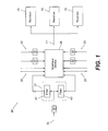
- FIG. 1 depicts a video/audio system 20 implementing the principles of the present invention.
- At least one video signal 22 and at least one audio signal 25 are received by an interface device 28.
- Each of the received video signals 22 defines a view of the race from a different perspective.
- the video signals 22 may be generated by different video cameras located at different locations around the stadium, including inside at least some of the vehicles participating in the race.
- each of the audio signals 25 defines different sounds associated with the race.
- at least one of the audio signals 25 may be generated from a microphone located close to the track or in one of the vehicles such that the audio signal 25 defines noise from the vehicles participating in the race.
- at least one of the audio signals 25 may define the comments of television commentators, and at least one of the audio signals 25 may define the comments of radio commentators.
- at least one of the audio signals 25 may define the comments between one of the drivers participating in the race and the driver's pit crew.
- the video and audio signals 22 and 25 can be unmodulated when transmitted to the interface device 28 and, therefore, do not need to be demodulated by the system 20. However, some of the video and audio signals 22 and 25 may need to be demodulated by the system 20. For example, at least one of the audio signals 25 defining the comments of the radio commentators may be modulated as a radio signal for transmission to radios located at or away from the stadium, and at least one of the video signals 25 may be modulated as a television signal for transmission to televisions located at or away from the stadium. In addition, the comments between a driver and the driver's pit crew are usually transmitted via ultra high frequency (UHF) radio waves, which are known to be modulated signals. Therefore, as shown by FIG. 1 , the system 20 preferably includes demodulators 32 configured to receive and demodulate the video and/or audio signals 22 and 25.
- UHF ultra high frequency
- a combined signal 35 which is comprised of at least one video signal 22 combined with at least one audio signal 25.
- the combined signal 35 may be a television signal modulated for transmission to televisions located at or away from the track stadium.
- a separator 37 preferably separates the combined signal 35 into its respective video signal 22 and audio signal 25, as shown by FIG. 1 .
- FIG. 1 depicts a possible implementation of the separator 37.
- the separator 37 includes an audio signal filter 41 designed to filter out any audio signals 25 from the combined signal 35 and to transmit the resulting video signal(s) 22 to interface device 28.
- the separator 37 also includes a video signal filter 43 designed to filter out any video signals 22 from the combined signal 35 and to transmit the resulting audio signal(s) 25 to interface device 28. If more than one video signal 22 or more than one audio signal 25 is included in the combined signal 35, then the separator 37 may include additional filters (not shown) to separate the multiple video and/or audio signals 22 and 25 into individual signals before transmitting the signals 22 and 25 to the interface device 28.
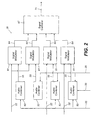
- FIG. 2 depicts a more detailed view of the interface device 28.
- the interface device 28 includes audio combiners 52 configured to receive audio signals 25 and to combine the received audio signals 25 into a single combined audio signal 55.
- each audio combiner 52 preferably receives a different combination of audio signals 25, although it is possible for any one of the combined signals 55 to include the same combination of audio signals 25 as any other combined signal 55. Note that when an audio combiner 52 receives only one audio signal 25, the combined signal 55 output by the combiner 52 matches the one signal 25 received by the combiner 52.
- one of the combined signals 55 may include an audio signal 25 defining comments between a driver and the driver's pit crew and also an audio signal 25 defining sounds ( i . e ., vehicular noises) received by a microphone located in the driver's vehicle.
- Another of the combined signals 55 may include the aforementioned audio signals 25 as well as an audio signal 25 defining a radio commentator's comments.
- Another combined signal 55 may only include an audio signal 25 defining a television commentator's comments. Accordingly, the combined signals 55 preferably define different combinations of sounds. It should be noted that combinations of audio signals 25 other than those described hereinabove are possible.
- each combined signal 55 is transmitted to a respective signal modulator 61.
- Each signal modulator 61 is also configured to receive a respective one of the video signals 25 received by the interface device 28.
- Each signal modulator 61 is configured to combine the received combined signal 55 and video signal 25 and to modulate the received signals 55 and 25 on a unique frequency range.
- the signal modulator 61 is then designed to transmit the modulated signal 64, which comprises the combined signal 55 and the video signal 25 received by the signal modulator 61, to a combiner 67.
- the combiner 67 is configured to combine each of the modulated signals 64 transmitted from each of the signal modulators 61 into a single combined ( i . e ., multiplexed) signal 71. This combined signal 71 is then transmitted to a plurality of receivers 75.
- a coaxial cable may be used to transmit the combined signal 71 to each of the receivers 75.
- the system 20 may include a wireless transmitter (not shown) that transmits the combined signal 71 to the receivers 75. Any technique for transmitting the combined signal 71 to the receivers 75 should be suitable for implementing the present invention.
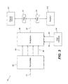
- Receiver 75 preferably includes a demodulator 82.
- the demodulator 82 is configured to demodulate the combined signal 71 and to separate ( i.e. , demultiplex) the combined signal 71 into signals 84 based on frequency, such that each signal 84 respectively corresponds with one of the modulated signals 64.
- the demodulator 82 recovers the individual signals 64 as signals 84, and each signal 84 is, therefore, defined by the same video and audio signals 22 and 25 that define its corresponding modulated signal 64. Therefore, like modulated signals 64, each signal 84 is preferably comprised of a unique combination of video and audio signals 22 and 25.
- Signals 84 are transmitted from demodulator 82 to a multiplexer 88, which also receives control signals 92 from a user interface 94.
- the user interface 94 preferably includes buttons or other types of switches that enable a spectator to select one of the signals 84 via control signals 92.
- the multiplexer 88 through techniques well known in the art, selects one of the signals 84 based on control signals 92 and outputs the selected signal 84 as output signal 97, as shown by FIG. 3 .
- the receiver 75 includes an audio signal filter 41 configured to filter the audio signal(s) 25 out of signal 97. Therefore, only the video signal(s) 22 within signal 97 are transmitted to a display screen 101, which is configured to render the received video signal(s) 22 ( i.e., display an image defined by the received video signal(s) 22) to the spectator.
- an audio signal filter 41 configured to filter the audio signal(s) 25 out of signal 97. Therefore, only the video signal(s) 22 within signal 97 are transmitted to a display screen 101, which is configured to render the received video signal(s) 22 ( i.e., display an image defined by the received video signal(s) 22) to the spectator.
- the receiver 75 also includes a video signal filter 43 configured to filter the video signal(s) 22 out of signal 97. Therefore, only the audio signal(s) 25 within signal 97 are transmitted to a speaker 103, which is configured to produce sounds defined by the received audio signal(s) 25, through techniques well known in the art.
- the display screen 101 and speaker 103 are included within a head mounted display (HMD), which is discussed in further detail hereinbelow.
- HMD head mounted display
- the spectator's experience may be enhanced. For example, when a head mounted display is used to show an in-car view from a camera located in a driver's car during an auto race, the spectator sees a similar view as the driver of the car. Because the head mounted display limits the spectator's peripheral view of the environment around him, the user naturally focuses on the view provided by the head mounted display. Therefore, the user may feel almost as if he were riding in the car along with the driver, thereby enhancing the spectator's experience.
- the head mounted display may similarly enhance a spectator's experience at other events, such as other sporting events, for example.
- the receiver 75 may be located at a spectator's stadium seat or other convenient location.
- the receiver 75 is portable, and a spectator may carry the receiver 75 with him and choose where he would like to view the images and hear the sounds produced by the receiver 75.
- the spectator may remain in his seat (or other convenient location) and control, by manipulating buttons or other types of switches in the user interface 94, which combination of video and audio signals 22 and 25 are respectively transmitted to display screen 101 and speaker 103. Therefore, the system 20 gives the spectator more flexibility in how the spectator views the race and, as a result, makes the race a more enjoyable experience.
- video signals 22 and audio signals 25 may be separately transmitted to receiver 75.
- video signals 22 may be processed and transmitted to receiver 75 via interface device 28 or other type of device, and audio signals 25 may be transmitted to receiver 75 via another device.
- the receiver 75 may then be configured to select the audio and video signals 25 and 22 to be transmitted to display device 101 and speaker 103.
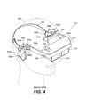
- FIGS. 4 and 5 depict a head mounted display (HMD) 151 described by U.S. Patent No. 5,903,395 .
- the HMD 151 includes a main component 152, containing electronics or optics used to provide a visual display to the spectator.
- the HMD 151 also includes left and right temple pieces 154a and 154b that may be used for assisting and holding the main portion 152 in the desired position to deliver video output to the spectator's eyes.
- a strap 156 can be provided to further assist in holding the apparatus in the desired position with respect to the head 158 of the spectator.
- a forehead brace 161 can be provided to further assist in proper positioning of the main portion 152.
- the forehead brace 161 is useful to transfer some of the weight of the apparatus to the spectator's forehead. This may provide a more comfortable configuration than having substantially all of the weight transferred via other components such as the temple pieces 154a and 154b, headstrap 156 and/or a nose bridge piece (not shown) that may be used in other types of HMDs.
- the forehead brace 161 extends back a distance 165 from the main portion 152 of the apparatus.
- there is an amount of space 166 between the eye position 167 of the spectator and the portion 168 of the apparatus which resides in front of the spectator's eyes sufficient to accommodate the spectator's eyeglasses, e.g. , about one inch or more (in one embodiment, about 25 mm).
- a connection is provided for establishing communication or data transfer to the HMD 151 which, in the depicted embodiment, involves a cable 171 mounted along the underside of the left temple piece 154b.
- the demodulator 82 FIG. 3
- multiplexer 88 multiplexer 88
- user interface 94 may be included in a device separate from the HMD 151 shown by FIGS. 4 and 5 .
- the cable 171 may transmit the signals 97 ( FIG. 3 ) to the filters 41 and 43, which are located in the main portion 152.
- the filtered signals from filters 41 and 43 may be respectively transmitted to display device 101 ( FIG. 3 ) and speaker 103 ( FIG. 3 ) via other cables or other types of connections.
- the display device 101 ( FIG. 3 ) is comprised of two liquid crystal displays (LCDs) 175 that receive video signals and produce images based on the received video signals through techniques well known in the art.
- LCDs 175 Each of the LCDs 175 is positioned in front of a respective eye of the spectator so that each eye of the spectator views an image produced by one of the LCDs 175.
- a rocker switch 179 can be used to provide control of a parameter which varies through a range, such as the volume of the sound produced by the speakers 103a and 103b.
- Other items that could be controlled in this fashion include, but are not limited to, tint, hue or contrast of the video, selection of a video and/or audio source such as channel selection, image brightness, audio tone ( i.e. , treble/bass control) and the like.
- a slider switch 181 can be used, e.g. , to select among discrete choices. For example, the slider switch 181 may be used to select left, right or no relative frame phasing, to select between stereo and non-stereoscopic views, etc .
- Other controls and/or indicators can also be used and can be mounted on various surfaces of the head-mounted apparatus of FIG. 4 .
- Left speaker 103a is movably attached to the end of the temple piece 154a, e.g. , by pivotable arm 185a which can be laterally adjusted to a mounting slot 188a in temple piece 154a.
- the speaker 103a can be held in position by friction or a detent tightener 189 can be used to secure the speaker 103a in the desired position.
- Right speaker 103b is similarly secured to temple piece 154b. Cables 191a and 191b are respectively used in the HMD 151 of FIG. 4 to provide the desired signals to the speakers 103a and 103b, respectively.
- the head strap 156 is preferably coupled to the temple pieces 154a and 154b via left and right strap pivots, loops or D-rings 195a and 195b.
- a length and/or tightness adjustment mechanism such as a buckle, for example, can be provided on the strap 156.
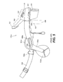
- the inventors have designed a HMD 250 that includes noise reduction devices 252a and 252b to reduce the amount of external noise heard by a spectator, as shown by FIG. 6 .
- HMD 250 includes temple pieces 259a and 259b that are connected to main portion 152.
- Main portion 152 and temple pieces 259a and 259b form a head mount to which other components of the HMD 151 can be coupled.
- Each noise reduction device 252a and 252b is similarly designed and is respectively coupled to the temple pieces 259a and 259b such that each device 252a and 252b fits over a respective ear of a spectator during use.
- each noise reduction device 252a and 252b forms a cup-shaped shell having a recess 267 ( FIGS. 7A-7D ).
- a padded cushion 271 such as the one described in U.S. Patent No. 4,856,118 entitled “Headphone Cushioning,” which is incorporated herein by reference, is positioned at the mouth of each device 252a and 252b as shown by FIGS. 7A-7D so that the noise reduction devices 252a and 252b comfortably engage the spectator's head during use.
- the spectator's ear fits into the recess 267, and the engaged device 252a or 252b blocks external noises from reaching the ear.
- devices 252a and 252b are similar to the earcup described in U.S. Patent No. 5,023,955 , entitled “Impact-AbsorbingSound-AttenuatingEarcup,” filed on April 13, 1989, by Murphy,11 et al ., which is incorporated herein by reference.
- each noise reduction device 252a and 252b is respectively coupled to and houses speakers 103a and 103b.
- the speakers 103a and 103b are respectively coupled to cables 191a and 191b, and produce sound corresponding to the audio signals transmitted via cables 191a and 191b. Consequently, in use, external noises are attenuated, yet the spectator can clearly hear the selected audio signals produced by the speakers 103a and 103b.
- Device 252a will be described in more detail hereafter. However, it should be apparent to one skilled in the art that device 252b includes the same features of device 252a except that device 252b is coupled to temple piece 259b (instead of piece 259a) and is designed to cover the spectator's opposite ear.
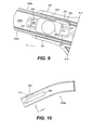
- the device 252a preferably includes a member 281 having a slot 283 adapted to receive temple piece 259a.
- the member 281 also includes a hole 286.
- a securing member 288 FIG. 9
- the securing member 288 is preferably secured to the temple piece 259a and the member 281 via any suitable technique.
- the securing member 288 may be screwed through the member 281 via hole 286,and the securing member 288 may also be screwed through a piece 291 ( FIG. 9 ) located on a side of the temple piece 259a opposite of the member 281. Therefore, the member 281 is secured to the temple piece 259a via the securing member 288.
- a piece 291 FIG. 9
- other devices and methodologies may be employed to secure the member 281 to temple piece 259a.
- a ridge 301 is formed on a side of the temple piece 259a that engages a wall 299 ( FIG. 7A ) of slot 283, when the temple piece 259a is received by slot 283.
- a portion of the wall 299 of slot 283 includes a series of notches 303 that are each capable of receiving the ridge 301.
- any force tending to move the device 252a relative to the temple piece 259a in the x-direction causes the ridge 301 to press against a portion of the wall 299 forming the notch 303, until the device 252a is pushed with a force sufficient to deform a flexible portion 311 of temple piece 259a.
- the flexible portion 311 is positioned adjacent to slot 312 to allow the flexible portion 311 to deform away from the surface 299. Once this occurs, the ridge 301 moves past the notch 303 more easily, allowing the temple piece 259a to move relative to member 281 and, therefore, device 252a.
- the flexible portion 311 preferably has sufficient elasticity to return to its undeformed state once the ridge 301 moves past the notch 303. Therefore, after moving past the aforementioned notch 303, the ridge 301 should engage a portion of the wall 299 forming another notch 303.
- the user can slide the device 252a in the x-direction along the length of the temple piece 259a causing the ridge 301 to be received by different notches 303 until the device 252a is properly positioned relative to the spectator's head ( i . e ., until the spectator'sear is comfortably positioned within the recess 267 of the device 252a).
- the spectator stops sliding the device 252a and the ridge 301 is received by one of the notches 303, the position of the device 252a relative to the temple piece 259a and, therefore, the spectator's head should remain constant until a force sufficient for deforming the flexible portion is exerted on the HMD 250.
- each device 252a is preferably fastened to an end of the strap 156. Therefore, each end of the strap 156 is coupled to each of the noise reduction devices 252a and 252b.
- each device 252a and 252b may include a clip, clasp, loop, ring 304 or other type of fastening device.
- the length of the strap 156 can be adjusted via conventional techniques to adjust the size of the HMD 250. Therefore, to don the HMD 250, a user places the forehead brace 161 ( FIG. 6 ) against his forehead and positions the strap 156 around the back of his head. The spectator then tightens the strap 156 ( i .
- the spectator adjusts the position of the devices 252a and 252b by respectively sliding the devices 252a and 252b along the length of the temple piece 259a and 259b in the x-direction until the devices 252a and 252b are properly positioned. Then, the spectator can further tighten the strap 156 as desired to further press the forehead brace 161 and the devices 252a and 252b against the spectator's head.
- tightening the strap 156 reduces the circumference of the HMD 250 thereby pressing each device 252a and 252b and the forehead brace 161 further against the spectator's head.
- the strap 156 is tightened, external noise is better attenuated, and it is less likely that the HMD 250 will move with respect to the spectator's head. Accordingly, the spectator can tighten or loosen the strap 156 as desired until the desired fit and desired noise reduction is achieved.
- the spectator would attend the race and acquire (as well as tune) a radio to receive the commentator's comments and a radio to receive the radio signals transmitted between the driver and the driver's pit crew. Then, the spectator would locate a monitor at the stadium displaying the in-car view that he desires to see, assuming that such a monitor is provided. The spectator would then remain within sight of the monitor and listen to the two radios. If the monitor is not located in a desirable location for viewing the race, the spectator would have to choose between viewing the monitor and viewing the race at a desirable location. Furthermore, the handling of multiple radios is generally cumbersome and distracting.
- the user attends the race and is provided a receiver 75 for his individual use.
- the receiver 75 is located at the spectator's seat within the stadium.
- the receiver 75 may be located at other convenient locations, and when the combined signal 71 is transmitted via a wireless transmitter, the spectator may carry the receiver 75 around with him to any desirable location in or around the stadium.
- the receiver preferably includes the HMD 250 depicted by FIG. 6 . Therefore, the spectator dons the HMD 250 such that the forehead brace 161 is pressed against his forehead and each noise reduction device 252a and 252b covers one of the spectator's ear. Then, the spectator adjusts the length of the strap 156 until the HMD 250 properly fits about his head. The spectator then manipulates buttons or other types of switches at user interface 94 to control which signal 84 is output by multiplexer 88 and, therefore, which signals 22 and 25 are transmitted via cable 171 to the HMD 250. Through techniques known in the art, images defined by the video signals transmitted along cable 171 are shown by display device 101 ( e.g.
- the spectator may use the receiver 75 to see the desired view of the race ( i . e ., the in-car view) and to hear the desired sounds of the race ( i . e ., the dialogue between the driver and the driver's pit crew, and the comments from the radio commentator).
- the interface device 28 preferably receives at least a video signal 22 defining the in-car view of his favorite driver and a plurality of audio signals 25 defining the dialogue between his favorite driver and the driver's pit crew, as well as the comments from his favorite radio commentator. At least one of the audio combiners 52 combines these audio signals 25 into a combined signal 55.
- One of the signal modulators 61 receives this combined signal 55 and the video signal 22 defining the desired in-car view.
- This video signal 22 is modulated and combined with the foregoing combined signal 55 by one of the signal modulators 61 to create a modulated signal 64.
- This modulated signal 64 is combined with other modulated signals 64 and transmitted to the spectator's receiver 75 via combiner 67.
- the demodulator 82 in the spectator's receiver 75 demodulates and separates the received signal 71 into separate signals 84. Based on the control signals 92 received from user interface 94, the multiplexer 88 allows only the signal 84 defined by the aforementioned video and audio signals 22 and 25 to pass. Therefore, these video and audio signals 22 and 25 are respectively transmitted to the display device 101 and speakers 103a and 103b and the spectator may enjoy the view and sounds that he selected.
- the signal 71 may be transmitted via satellites and/or communication networks to various locations around the world, and the spectator may select the view and sounds he prefers the most from just about any location capable of receiving signal 71.
- the receiver 75 may be retrieved from the spectator after the spectator is finished viewing the event so that the receiver can be provided to another spectator for another event at the stadium. Each spectator is preferably charged a usage fee for the spectator's use of the receiver 75. It should be noted that a portion of the receiver 75 may be installed at the spectator's seat such that user only needs to retrieve the HMD 151 and/or other components of the receiver 75 during the event and return the retrieved components after the event. Furthermore, the entire receiver 75 may be installed at the spectator's seat such that spectator only needs to pay for the use of the receiver.
- one of the audio signals 25 may be desirable for one of the audio signals 25 to have a higher amplitude than the other audio signals 25.
- a spectator may desire to hear comments from a radio commentator unless a communication between his favorite driver and the driver's pit crew occurs. When the a communication between the driver and the driver's crew occurs, the spectator would rather listen to this communication instead of the radio commentator's comments.
- one of the audio combiners 25 is preferably used to combine a first audio signal 25 defining the radio commentator's comments and a second audio signal defining the communications between the driver and the driver's pit crew preferably increases the amplitude of the second audio signal 25 relative to the first audio signal. This may be accomplished by increasing the amplitude of the second audio signal 25 with an amplifier or by attenuating the amplitude of the first audio signal 25 with an attenuator. Therefore, when the combined signal 55 produced by the aforementioned audio combiner 52 is ultimately received by the spectator's receiver 75, which produces sound based on this combined signal 55, the user hears the radio commentator's comments when there is no communication between the driver and the driver's crew.
- the present invention has been described herein in the context of auto racing.
- the system 20 may be useful in other applications as well.
- the system 20 would be useful in any application where it is desirable for the user to control the types of views and sounds of an event that are presented to the user.
- the present invention could be particularly useful in any type of sporting event or other type of event attended by a large number of people.
Landscapes
- Engineering & Computer Science (AREA)
- Signal Processing (AREA)
- Multimedia (AREA)
- Human Computer Interaction (AREA)
- Databases & Information Systems (AREA)
- Acoustics & Sound (AREA)
- Physics & Mathematics (AREA)
- Software Systems (AREA)
- Two-Way Televisions, Distribution Of Moving Picture Or The Like (AREA)
- Television Systems (AREA)
- Headphones And Earphones (AREA)
- Studio Devices (AREA)
- Studio Circuits (AREA)
Applications Claiming Priority (5)
| Application Number | Priority Date | Filing Date | Title |
|---|---|---|---|
| US12334199P | 1999-03-08 | 1999-03-08 | |
| US09/322,411 US6578203B1 (en) | 1999-03-08 | 1999-05-28 | Audio/video signal distribution system for head mounted displays |
| US13732399P | 1999-06-03 | 1999-06-03 | |
| US09/386,613 US7124425B1 (en) | 1999-03-08 | 1999-08-31 | Audio/video system and method utilizing a head mounted apparatus with noise attenuation |
| EP00917791A EP1166596B1 (fr) | 1999-03-08 | 2000-03-08 | Systeme video/audio et procede permettant a un utilisateur de choisir differents vues et sons lies a un evenement |
Related Parent Applications (1)
| Application Number | Title | Priority Date | Filing Date |
|---|---|---|---|
| EP00917791A Division EP1166596B1 (fr) | 1999-03-08 | 2000-03-08 | Systeme video/audio et procede permettant a un utilisateur de choisir differents vues et sons lies a un evenement |
Publications (2)
| Publication Number | Publication Date |
|---|---|
| EP2114092A1 true EP2114092A1 (fr) | 2009-11-04 |
| EP2114092B1 EP2114092B1 (fr) | 2016-08-10 |
Family
ID=27494481
Family Applications (2)
| Application Number | Title | Priority Date | Filing Date |
|---|---|---|---|
| EP00917791A Expired - Lifetime EP1166596B1 (fr) | 1999-03-08 | 2000-03-08 | Systeme video/audio et procede permettant a un utilisateur de choisir differents vues et sons lies a un evenement |
| EP09010070.2A Expired - Lifetime EP2114092B1 (fr) | 1999-03-08 | 2000-03-08 | Système audio/vidéo et procédé permettant a un utilisateur de choisir différents vues et sons associés à un événement |
Family Applications Before (1)
| Application Number | Title | Priority Date | Filing Date |
|---|---|---|---|
| EP00917791A Expired - Lifetime EP1166596B1 (fr) | 1999-03-08 | 2000-03-08 | Systeme video/audio et procede permettant a un utilisateur de choisir differents vues et sons lies a un evenement |
Country Status (11)
| Country | Link |
|---|---|
| US (1) | US7124425B1 (fr) |
| EP (2) | EP1166596B1 (fr) |
| JP (1) | JP2002539701A (fr) |
| CN (1) | CN100353771C (fr) |
| AT (1) | ATE443411T1 (fr) |
| AU (1) | AU779175B2 (fr) |
| CA (2) | CA2369832C (fr) |
| DE (1) | DE60042967D1 (fr) |
| ES (1) | ES2331175T3 (fr) |
| PT (1) | PT1166596E (fr) |
| WO (1) | WO2000054554A1 (fr) |
Cited By (1)
| Publication number | Priority date | Publication date | Assignee | Title |
|---|---|---|---|---|
| US10932029B2 (en) | 2017-03-15 | 2021-02-23 | Sony Corporation | Headphones |
Families Citing this family (122)
| Publication number | Priority date | Publication date | Assignee | Title |
|---|---|---|---|---|
| US7162532B2 (en) | 1998-02-23 | 2007-01-09 | Koehler Steven M | System and method for listening to teams in a race event |
| US6578203B1 (en) * | 1999-03-08 | 2003-06-10 | Tazwell L. Anderson, Jr. | Audio/video signal distribution system for head mounted displays |
| US20020057364A1 (en) | 1999-05-28 | 2002-05-16 | Anderson Tazwell L. | Electronic handheld audio/video receiver and listening/viewing device |
| US7210160B2 (en) * | 1999-05-28 | 2007-04-24 | Immersion Entertainment, L.L.C. | Audio/video programming and charging system and method |
| JP2002051320A (ja) * | 2000-05-10 | 2002-02-15 | Sharp Corp | データ記録装置、それを用いた興行記録システム、興行用入場券、データ記録のためのプログラムおよびそのプログラムを記録したコンピュータ読み取り可能な記録媒体 |
| US7461936B2 (en) * | 2000-06-02 | 2008-12-09 | Oakley, Inc. | Eyeglasses with detachable adjustable electronics module |
| US8482488B2 (en) | 2004-12-22 | 2013-07-09 | Oakley, Inc. | Data input management system for wearable electronically enabled interface |
| US6325507B1 (en) | 2000-06-02 | 2001-12-04 | Oakley, Inc. | Eyewear retention system extending across the top of a wearer's head |
| US20120105740A1 (en) | 2000-06-02 | 2012-05-03 | Oakley, Inc. | Eyewear with detachable adjustable electronics module |
| US8583027B2 (en) | 2000-10-26 | 2013-11-12 | Front Row Technologies, Llc | Methods and systems for authorizing computing devices for receipt of venue-based data based on the location of a user |
| US7630721B2 (en) | 2000-06-27 | 2009-12-08 | Ortiz & Associates Consulting, Llc | Systems, methods and apparatuses for brokering data between wireless devices and data rendering devices |
| US7149549B1 (en) | 2000-10-26 | 2006-12-12 | Ortiz Luis M | Providing multiple perspectives for a venue activity through an electronic hand held device |
| US7782363B2 (en) | 2000-06-27 | 2010-08-24 | Front Row Technologies, Llc | Providing multiple video perspectives of activities through a data network to a remote multimedia server for selective display by remote viewing audiences |
| US7796162B2 (en) | 2000-10-26 | 2010-09-14 | Front Row Technologies, Llc | Providing multiple synchronized camera views for broadcast from a live venue activity to remote viewers |
| US7812856B2 (en) | 2000-10-26 | 2010-10-12 | Front Row Technologies, Llc | Providing multiple perspectives of a venue activity to electronic wireless hand held devices |
| CA2348353A1 (fr) | 2001-05-22 | 2002-11-22 | Marc Arseneau | Systeme de radiodiffusion locale |
| US7013009B2 (en) | 2001-06-21 | 2006-03-14 | Oakley, Inc. | Eyeglasses with wireless communication features |
| US8409024B2 (en) * | 2001-09-12 | 2013-04-02 | Pillar Vision, Inc. | Trajectory detection and feedback system for golf |
| US7593687B2 (en) | 2003-10-07 | 2009-09-22 | Immersion Entertainment, Llc | System and method for providing event spectators with audio/video signals pertaining to remote events |
| US20050280705A1 (en) * | 2004-05-20 | 2005-12-22 | Immersion Entertainment | Portable receiver device |
| AU2006272401B2 (en) | 2005-07-22 | 2011-03-31 | Fanvision Entertainment Llc | System and methods for enhancing the experience of spectators attending a live sporting event |
| US8042140B2 (en) | 2005-07-22 | 2011-10-18 | Kangaroo Media, Inc. | Buffering content on a handheld electronic device |
| US8929870B2 (en) | 2006-02-27 | 2015-01-06 | Qualcomm Incorporated | Methods, apparatus, and system for venue-cast |
| US20070240190A1 (en) * | 2006-04-07 | 2007-10-11 | Marc Arseneau | Method and system for enhancing the experience of a spectator attending a live sporting event |
| WO2008035612A1 (fr) * | 2006-09-19 | 2008-03-27 | Nikon Corporation | Dispositif de sortie et écran pouvant être porté |
| EP2095178B1 (fr) | 2006-12-14 | 2015-08-12 | Oakley, Inc. | Interface audiovisuelle haute résolution pouvant être portée |
| US9136957B1 (en) * | 2006-12-21 | 2015-09-15 | Sprint Communications Company L.P. | Mobile device activation for events |
| US8922503B2 (en) | 2008-01-04 | 2014-12-30 | Tactus Technology, Inc. | User interface system |
| US9063627B2 (en) | 2008-01-04 | 2015-06-23 | Tactus Technology, Inc. | User interface and methods |
| US9274612B2 (en) | 2008-01-04 | 2016-03-01 | Tactus Technology, Inc. | User interface system |
| US9367132B2 (en) | 2008-01-04 | 2016-06-14 | Tactus Technology, Inc. | User interface system |
| US8922510B2 (en) | 2008-01-04 | 2014-12-30 | Tactus Technology, Inc. | User interface system |
| US8947383B2 (en) | 2008-01-04 | 2015-02-03 | Tactus Technology, Inc. | User interface system and method |
| US9298261B2 (en) | 2008-01-04 | 2016-03-29 | Tactus Technology, Inc. | Method for actuating a tactile interface layer |
| US9013417B2 (en) | 2008-01-04 | 2015-04-21 | Tactus Technology, Inc. | User interface system |
| US8547339B2 (en) | 2008-01-04 | 2013-10-01 | Tactus Technology, Inc. | System and methods for raised touch screens |
| US9552065B2 (en) | 2008-01-04 | 2017-01-24 | Tactus Technology, Inc. | Dynamic tactile interface |
| US8553005B2 (en) | 2008-01-04 | 2013-10-08 | Tactus Technology, Inc. | User interface system |
| US9612659B2 (en) | 2008-01-04 | 2017-04-04 | Tactus Technology, Inc. | User interface system |
| US9430074B2 (en) | 2008-01-04 | 2016-08-30 | Tactus Technology, Inc. | Dynamic tactile interface |
| US9588683B2 (en) | 2008-01-04 | 2017-03-07 | Tactus Technology, Inc. | Dynamic tactile interface |
| US8154527B2 (en) | 2008-01-04 | 2012-04-10 | Tactus Technology | User interface system |
| US8570295B2 (en) | 2008-01-04 | 2013-10-29 | Tactus Technology, Inc. | User interface system |
| US8928621B2 (en) | 2008-01-04 | 2015-01-06 | Tactus Technology, Inc. | User interface system and method |
| US8456438B2 (en) | 2008-01-04 | 2013-06-04 | Tactus Technology, Inc. | User interface system |
| US8179375B2 (en) | 2008-01-04 | 2012-05-15 | Tactus Technology | User interface system and method |
| US9280224B2 (en) | 2012-09-24 | 2016-03-08 | Tactus Technology, Inc. | Dynamic tactile interface and methods |
| US20160187981A1 (en) | 2008-01-04 | 2016-06-30 | Tactus Technology, Inc. | Manual fluid actuator |
| US8243038B2 (en) | 2009-07-03 | 2012-08-14 | Tactus Technologies | Method for adjusting the user interface of a device |
| US9052790B2 (en) | 2008-01-04 | 2015-06-09 | Tactus Technology, Inc. | User interface and methods |
| US8922502B2 (en) | 2008-01-04 | 2014-12-30 | Tactus Technology, Inc. | User interface system |
| US9720501B2 (en) | 2008-01-04 | 2017-08-01 | Tactus Technology, Inc. | Dynamic tactile interface |
| US9423875B2 (en) | 2008-01-04 | 2016-08-23 | Tactus Technology, Inc. | Dynamic tactile interface with exhibiting optical dispersion characteristics |
| US9557915B2 (en) | 2008-01-04 | 2017-01-31 | Tactus Technology, Inc. | Dynamic tactile interface |
| US8970403B2 (en) | 2008-01-04 | 2015-03-03 | Tactus Technology, Inc. | Method for actuating a tactile interface layer |
| US9128525B2 (en) | 2008-01-04 | 2015-09-08 | Tactus Technology, Inc. | Dynamic tactile interface |
| JP4737251B2 (ja) | 2008-08-20 | 2011-07-27 | ソニー株式会社 | ヘッドホン |
| US8635645B2 (en) * | 2008-09-30 | 2014-01-21 | Qualcomm Incorporated | Apparatus and methods of providing and receiving venue level transmissions and services |
| CN101753940A (zh) * | 2008-12-12 | 2010-06-23 | 康佳集团股份有限公司 | 可录制电视节目的电视机 |
| US8254304B2 (en) * | 2008-12-14 | 2012-08-28 | Qualcomm Incorporated | Channel capacity adaptive repeater |
| US9588684B2 (en) | 2009-01-05 | 2017-03-07 | Tactus Technology, Inc. | Tactile interface for a computing device |
| WO2010078597A1 (fr) | 2009-01-05 | 2010-07-08 | Tactus Technology, Inc. | Système d'interface utilisateur |
| WO2010078596A1 (fr) | 2009-01-05 | 2010-07-08 | Tactus Technology, Inc. | Système d'interface utilisateur |
| US9137495B2 (en) * | 2009-01-30 | 2015-09-15 | Yinzcam, Inc. | Systems and methods for providing interactive video services |
| AU2009201810A1 (en) * | 2009-05-06 | 2010-11-25 | Jorge Miguel Pereira | Ear Muffs |
| US20100309290A1 (en) * | 2009-06-08 | 2010-12-09 | Stephen Brooks Myers | System for capture and display of stereoscopic content |
| CN102483675B (zh) | 2009-07-03 | 2015-09-09 | 泰克图斯科技公司 | 用户界面增强系统 |
| US8879440B2 (en) * | 2009-09-29 | 2014-11-04 | Qualcomm Incorporated | Method and apparatus for ad hoc venue-cast service |
| US9239623B2 (en) | 2010-01-05 | 2016-01-19 | Tactus Technology, Inc. | Dynamic tactile interface |
| US8619035B2 (en) | 2010-02-10 | 2013-12-31 | Tactus Technology, Inc. | Method for assisting user input to a device |
| US9223134B2 (en) | 2010-02-28 | 2015-12-29 | Microsoft Technology Licensing, Llc | Optical imperfections in a light transmissive illumination system for see-through near-eye display glasses |
| US9134534B2 (en) | 2010-02-28 | 2015-09-15 | Microsoft Technology Licensing, Llc | See-through near-eye display glasses including a modular image source |
| US8477425B2 (en) | 2010-02-28 | 2013-07-02 | Osterhout Group, Inc. | See-through near-eye display glasses including a partially reflective, partially transmitting optical element |
| US8482859B2 (en) | 2010-02-28 | 2013-07-09 | Osterhout Group, Inc. | See-through near-eye display glasses wherein image light is transmitted to and reflected from an optically flat film |
| US20150309316A1 (en) | 2011-04-06 | 2015-10-29 | Microsoft Technology Licensing, Llc | Ar glasses with predictive control of external device based on event input |
| US9128281B2 (en) | 2010-09-14 | 2015-09-08 | Microsoft Technology Licensing, Llc | Eyepiece with uniformly illuminated reflective display |
| US9182596B2 (en) | 2010-02-28 | 2015-11-10 | Microsoft Technology Licensing, Llc | See-through near-eye display glasses with the optical assembly including absorptive polarizers or anti-reflective coatings to reduce stray light |
| US8488246B2 (en) | 2010-02-28 | 2013-07-16 | Osterhout Group, Inc. | See-through near-eye display glasses including a curved polarizing film in the image source, a partially reflective, partially transmitting optical element and an optically flat film |
| US9759917B2 (en) | 2010-02-28 | 2017-09-12 | Microsoft Technology Licensing, Llc | AR glasses with event and sensor triggered AR eyepiece interface to external devices |
| US9129295B2 (en) | 2010-02-28 | 2015-09-08 | Microsoft Technology Licensing, Llc | See-through near-eye display glasses with a fast response photochromic film system for quick transition from dark to clear |
| US9341843B2 (en) | 2010-02-28 | 2016-05-17 | Microsoft Technology Licensing, Llc | See-through near-eye display glasses with a small scale image source |
| US10180572B2 (en) | 2010-02-28 | 2019-01-15 | Microsoft Technology Licensing, Llc | AR glasses with event and user action control of external applications |
| US8467133B2 (en) | 2010-02-28 | 2013-06-18 | Osterhout Group, Inc. | See-through display with an optical assembly including a wedge-shaped illumination system |
| US9097891B2 (en) | 2010-02-28 | 2015-08-04 | Microsoft Technology Licensing, Llc | See-through near-eye display glasses including an auto-brightness control for the display brightness based on the brightness in the environment |
| US9091851B2 (en) | 2010-02-28 | 2015-07-28 | Microsoft Technology Licensing, Llc | Light control in head mounted displays |
| US9366862B2 (en) | 2010-02-28 | 2016-06-14 | Microsoft Technology Licensing, Llc | System and method for delivering content to a group of see-through near eye display eyepieces |
| US9229227B2 (en) | 2010-02-28 | 2016-01-05 | Microsoft Technology Licensing, Llc | See-through near-eye display glasses with a light transmissive wedge shaped illumination system |
| US9285589B2 (en) | 2010-02-28 | 2016-03-15 | Microsoft Technology Licensing, Llc | AR glasses with event and sensor triggered control of AR eyepiece applications |
| US20120249797A1 (en) | 2010-02-28 | 2012-10-04 | Osterhout Group, Inc. | Head-worn adaptive display |
| AU2011220382A1 (en) | 2010-02-28 | 2012-10-18 | Microsoft Corporation | Local advertising content on an interactive head-mounted eyepiece |
| US8472120B2 (en) | 2010-02-28 | 2013-06-25 | Osterhout Group, Inc. | See-through near-eye display glasses with a small scale image source |
| US9097890B2 (en) | 2010-02-28 | 2015-08-04 | Microsoft Technology Licensing, Llc | Grating in a light transmissive illumination system for see-through near-eye display glasses |
| WO2012054780A1 (fr) | 2010-10-20 | 2012-04-26 | Tactus Technology | Système d'interface utilisateur |
| US9330499B2 (en) * | 2011-05-20 | 2016-05-03 | Microsoft Technology Licensing, Llc | Event augmentation with real-time information |
| US8175297B1 (en) | 2011-07-06 | 2012-05-08 | Google Inc. | Ad hoc sensor arrays |
| FR2982110B3 (fr) * | 2012-01-10 | 2014-03-14 | Samsung Electronics Co Ltd | Dispositif de lunettes pour visionner une image d'affichage |
| GB2501767A (en) | 2012-05-04 | 2013-11-06 | Sony Comp Entertainment Europe | Noise cancelling headset |
| GB2501768A (en) | 2012-05-04 | 2013-11-06 | Sony Comp Entertainment Europe | Head mounted display |
| US9519640B2 (en) * | 2012-05-04 | 2016-12-13 | Microsoft Technology Licensing, Llc | Intelligent translations in personal see through display |
| CN102739323B (zh) * | 2012-06-16 | 2013-09-04 | 天地融科技股份有限公司 | 音频数据传输方法 |
| US10176635B2 (en) | 2012-06-28 | 2019-01-08 | Microsoft Technology Licensing, Llc | Saving augmented realities |
| US9405417B2 (en) | 2012-09-24 | 2016-08-02 | Tactus Technology, Inc. | Dynamic tactile interface and methods |
| US9019174B2 (en) | 2012-10-31 | 2015-04-28 | Microsoft Technology Licensing, Llc | Wearable emotion detection and feedback system |
| CN205177388U (zh) | 2013-03-15 | 2016-04-20 | 奥克利有限公司 | 目镜系统 |
| CN205691887U (zh) | 2013-06-12 | 2016-11-16 | 奥克利有限公司 | 模块化通信系统和眼镜通信系统 |
| US9557813B2 (en) | 2013-06-28 | 2017-01-31 | Tactus Technology, Inc. | Method for reducing perceived optical distortion |
| US9317120B2 (en) * | 2013-09-06 | 2016-04-19 | Immersion Corporation | Multiplexing and demultiplexing haptic signals |
| USD738374S1 (en) | 2013-11-15 | 2015-09-08 | Oculus Vr, Llc | Virtual reality headset |
| WO2015173996A1 (fr) * | 2014-05-13 | 2015-11-19 | パナソニックIpマネジメント株式会社 | Appareil de montage |
| USD732028S1 (en) * | 2014-12-09 | 2015-06-16 | Samsung Electronics Co., Ltd. | Head-mounted display device |
| US9472025B2 (en) * | 2015-01-21 | 2016-10-18 | Oculus Vr, Llc | Compressible eyecup assemblies in a virtual reality headset |
| CA3032812A1 (fr) | 2016-08-04 | 2018-02-08 | Reification Inc. | Procedes de localisation et cartographie simultanes (slam) et appareil et systemes associes |
| US11507216B2 (en) | 2016-12-23 | 2022-11-22 | Realwear, Inc. | Customizing user interfaces of binary applications |
| US10437070B2 (en) | 2016-12-23 | 2019-10-08 | Realwear, Inc. | Interchangeable optics for a head-mounted display |
| US10365493B2 (en) * | 2016-12-23 | 2019-07-30 | Realwear, Incorporated | Modular components for a head-mounted display |
| US10620910B2 (en) | 2016-12-23 | 2020-04-14 | Realwear, Inc. | Hands-free navigation of touch-based operating systems |
| US10393312B2 (en) | 2016-12-23 | 2019-08-27 | Realwear, Inc. | Articulating components for a head-mounted display |
| US10936872B2 (en) | 2016-12-23 | 2021-03-02 | Realwear, Inc. | Hands-free contextually aware object interaction for wearable display |
| US11099716B2 (en) | 2016-12-23 | 2021-08-24 | Realwear, Inc. | Context based content navigation for wearable display |
| US10278001B2 (en) | 2017-05-12 | 2019-04-30 | Microsoft Technology Licensing, Llc | Multiple listener cloud render with enhanced instant replay |
| CN111788779B (zh) | 2018-02-26 | 2023-03-31 | 萨微网络有限公司 | 用于向多个接收器广播数字数据的系统和方法 |
| US10656670B2 (en) | 2018-06-04 | 2020-05-19 | Htc Corporation | Head-mounted display device |
Citations (5)
| Publication number | Priority date | Publication date | Assignee | Title |
|---|---|---|---|---|
| EP0277014A2 (fr) * | 1987-01-30 | 1988-08-03 | Sony Corporation | Systèmes de communication pour service et divertissement |
| US4853764A (en) * | 1988-09-16 | 1989-08-01 | Pedalo, Inc. | Method and apparatus for screenless panoramic stereo TV system |
| US5513384A (en) * | 1993-11-09 | 1996-04-30 | Inner Ear Communications, Inc. | System and method for providing multiple broadcasts of audio information to spectators |
| GB2313755A (en) * | 1996-05-29 | 1997-12-03 | Gen Instrument Corp | Processing packetised data streams |
| US5742521A (en) * | 1993-09-10 | 1998-04-21 | Criticom Corp. | Vision system for viewing a sporting event |
Family Cites Families (106)
| Publication number | Priority date | Publication date | Assignee | Title |
|---|---|---|---|---|
| US1527802A (en) | 1923-01-17 | 1925-02-24 | Huggins Kenneth Levi | Soundproof attachment for ear phones |
| US1648832A (en) | 1924-08-15 | 1927-11-08 | Urban Ladislaus | Phone pillar |
| US2603724A (en) | 1948-10-30 | 1952-07-15 | Rca Corp | Sound translating device arranged to eliminate extraneous sound |
| US2856469A (en) | 1955-12-05 | 1958-10-14 | Morse Milton | Earphone barrier device |
| US2946860A (en) | 1957-01-03 | 1960-07-26 | Rca Corp | Headset |
| DE3042269A1 (de) | 1980-11-08 | 1982-06-09 | Basf Ag, 6700 Ludwigshafen | Verfahren und anordnungen zum veraendern der audioinformation in einem audio/video-aufzeichnungs/wiedergabesystem |
| US4965825A (en) | 1981-11-03 | 1990-10-23 | The Personalized Mass Media Corporation | Signal processing apparatus and methods |
| JPS58136181A (ja) | 1982-02-05 | 1983-08-13 | Sony Corp | 受信装置 |
| JPS58121473U (ja) | 1982-02-09 | 1983-08-18 | ソニー株式会社 | 音声多重受信機 |
| US4504861A (en) | 1982-02-18 | 1985-03-12 | Emcee A Division Of Electronics, Missiles & Communications, Inc. | Portable TV transmitter |
| CA1214868A (fr) | 1982-11-19 | 1986-12-02 | Junzo Tokunaka | Appareil d'enregistrement et/ou de lecture de signaux video et audio |
| GB8308484D0 (en) | 1983-03-28 | 1983-05-05 | Racal Safety Ltd | Hearing protectors |
| US4605950A (en) | 1983-09-20 | 1986-08-12 | Cbs Inc. | Two channel compatible high definition television broadcast system |
| US4620068A (en) | 1984-06-06 | 1986-10-28 | Remic Corporation | Communication headset |
| SE450085B (sv) | 1984-07-04 | 1987-06-09 | Bo Gunnar Lonnstedt | Bygel for t ex horselskydd |
| US5023707A (en) | 1985-12-02 | 1991-06-11 | Media Transference International, Ltd. | System for combining multiple audio channels into the baseband video signal and the recovery of the audio channels therefrom |
| US4856089A (en) | 1986-07-28 | 1989-08-08 | Horton Lee A | Combined eye covering and ear covering assembly |
| SE8604244L (sv) | 1986-10-06 | 1988-04-11 | Finnveden Holding Ab | Tryckring for horselskydd |
| US4727585A (en) | 1986-11-24 | 1988-02-23 | Telex Communications, Inc. | Adjustable tension support band for headset |
| US4887152A (en) | 1987-01-30 | 1989-12-12 | Sony Corporation | Message delivery system operable in an override mode upon reception of a command signal |
| US4856118A (en) | 1987-02-11 | 1989-08-15 | Bose Corporation | Headphone cushioning |
| US4764817A (en) | 1987-06-10 | 1988-08-16 | Leonard Bloom | Video recording camera |
| US4864425A (en) | 1987-06-10 | 1989-09-05 | Leonard Bloom | Video recording camera |
| US4809079A (en) | 1987-06-10 | 1989-02-28 | Leonard Bloom | Video recording camera |
| US4791477A (en) | 1987-06-10 | 1988-12-13 | Leonard Bloom | Video recording camera |
| US4855827A (en) | 1987-07-21 | 1989-08-08 | Worlds Of Wonder, Inc. | Method of providing identification, other digital data and multiple audio tracks in video systems |
| SE8703414L (sv) | 1987-09-02 | 1989-03-03 | Kompositprodukter Sk Fm Ab | Hoerselskydd |
| US4983967A (en) | 1987-10-16 | 1991-01-08 | I.R.T. Electronics Pty. Limited | Transmission of audio in a video signal |
| US4802243A (en) | 1987-10-26 | 1989-02-07 | Griffiths John W | Acoustic headgear-sun visor assembly |
| JPH01136277A (ja) | 1987-11-24 | 1989-05-29 | Toshiba Corp | 所見入力装置 |
| GB2215083B (en) | 1988-02-16 | 1992-02-05 | Graham Green | Optical aid for attachment to a human body. |
| SE463803B (sv) | 1988-04-28 | 1991-01-28 | Milmas Ab | Fjaedrande monteringsarm foer hoerselskydd |
| JPH0297198A (ja) | 1988-10-03 | 1990-04-09 | Sony Corp | ヘッドホン装置 |
| US5128765A (en) | 1988-11-29 | 1992-07-07 | Visual Subliminal Technologies, Inc. | System for implementing the synchronized superimposition of subliminal signals |
| US4982278A (en) | 1989-02-15 | 1991-01-01 | Dahl Thomas R | Binocular stereovision |
| US5023955A (en) | 1989-04-13 | 1991-06-18 | Gentex Corporation | Impact-absorbing sound-attenuating earcup |
| JP2785337B2 (ja) | 1989-06-19 | 1998-08-13 | ソニー株式会社 | 磁気記録再生装置 |
| US5020163A (en) | 1989-06-29 | 1991-06-04 | Gentex Corporation | Earseal for sound-attenuating earcup assembly |
| US4958697A (en) | 1989-09-11 | 1990-09-25 | The United States Of America As Represented By The Secretary Of The Army | Anatomically shaped earseals for headsets |
| US5046192A (en) | 1989-09-26 | 1991-09-10 | Ryder International Corporation | Headset sun visor |
| US5133081A (en) | 1989-11-03 | 1992-07-21 | Mayo Scott T | Remotely controllable message broadcast system including central programming station, remote message transmitters and repeaters |
| JPH03203478A (ja) * | 1989-12-28 | 1991-09-05 | Sony Corp | 顔面装着型視覚装置 |
| US5130815A (en) | 1990-07-20 | 1992-07-14 | Mti Associates | Method and apparatus for encoding a video signal having multi-language capabilities |
| US5138440A (en) | 1990-10-29 | 1992-08-11 | General Instrument Corporation | Method and apparatus for communicating a plurality of asynchronous signals over a digital communication path |
| US5719588A (en) | 1991-03-08 | 1998-02-17 | Nashua Corporation | Viewing device |
| US5185807A (en) | 1991-05-08 | 1993-02-09 | David Clark Company Incorporated | Headset with multi-position stirrup assemblies |
| US5138722A (en) | 1991-07-02 | 1992-08-18 | David Clark Company Inc. | Headset ear seal |
| US5179736A (en) | 1991-09-30 | 1993-01-19 | Scanlon Thomas A | Combination headset and face mask device |
| DE69221987T2 (de) | 1991-11-01 | 1998-02-05 | Sega Enterprises Kk | Am Kopf befestigte Abbildungsvorrichtung |
| US5880773A (en) | 1991-12-27 | 1999-03-09 | Sony Corporation | Head mounted display configured to a user's physical features |
| US5289272A (en) * | 1992-02-18 | 1994-02-22 | Hughes Aircraft Company | Combined data, audio and video distribution system in passenger aircraft |
| US5252069A (en) | 1992-03-30 | 1993-10-12 | Richard A. Lamb | Instrument flight rules (IFR) training device |
| US5321416A (en) | 1992-07-27 | 1994-06-14 | Virtual Research Systems | Head-mounted visual display apparatus |
| US5594470A (en) | 1992-10-02 | 1997-01-14 | Teletransaction, Inc. | Highly integrated portable electronic work slate unit |
| KR960011030B1 (ko) | 1992-11-20 | 1996-08-16 | 마쯔시다덴기산교 가부시기가이샤 | 복수텔레비젼 신호기록재생방법 및 그것을 사용한 기록재생장치 |
| JPH06194600A (ja) | 1992-12-25 | 1994-07-15 | Sony Corp | 表示装置 |
| US5420381A (en) | 1993-04-19 | 1995-05-30 | Cabot Safety Corporation | Acoustical earmuff |
| US5596647A (en) | 1993-06-01 | 1997-01-21 | Matsushita Avionics Development Corporation | Integrated video and audio signal distribution system and method for use on commercial aircraft and other vehicles |
| US5546099A (en) | 1993-08-02 | 1996-08-13 | Virtual Vision | Head mounted display system with light blocking structure |
| JPH0772446A (ja) | 1993-09-01 | 1995-03-17 | Sharp Corp | 表示システム |
| JPH07107446A (ja) * | 1993-09-30 | 1995-04-21 | Toshiba Corp | 関連番組情報供給装置 |
| US5440197A (en) | 1993-10-05 | 1995-08-08 | Tir Technologies, Inc. | Backlighting apparatus for uniformly illuminating a display panel |
| US5815126A (en) | 1993-10-22 | 1998-09-29 | Kopin Corporation | Monocular portable communication and display system |
| US5631693A (en) | 1993-10-25 | 1997-05-20 | Antec Corporation | Method and apparatus for providing on demand services in a subscriber system |
| US5576843A (en) | 1993-10-29 | 1996-11-19 | Time Warner Entertainment Co., L.P. | System and method for controlling play of multiple dialog audio tracks of a software carrier |
| US5600365A (en) | 1994-01-28 | 1997-02-04 | Sony Corporation | Multiple audio and video signal providing apparatus |
| US5463428A (en) | 1994-02-08 | 1995-10-31 | Stereographics Corporation | Wireless active eyewear for stereoscopic applications |
| US5510828A (en) | 1994-03-01 | 1996-04-23 | Lutterbach; R. Steven | Interactive video display system |
| US5642221A (en) | 1994-03-09 | 1997-06-24 | Optics 1, Inc. | Head mounted display system |
| US5537141A (en) | 1994-04-15 | 1996-07-16 | Actv, Inc. | Distance learning system providing individual television participation, audio responses and memory for every student |
| US5481478A (en) | 1994-06-03 | 1996-01-02 | Palmieri; Herman D. | Broadcast system for a facility |
| US5696521A (en) | 1994-06-22 | 1997-12-09 | Astounding Technologies (M) Sdn. Bhd. | Video headset |
| US5631369A (en) * | 1994-08-31 | 1997-05-20 | Eli Lilly And Company | Process for preparing benzoic acid derivative intermediates and benzothiophene pharmaceutical agents |
| US5903395A (en) | 1994-08-31 | 1999-05-11 | I-O Display Systems Llc | Personal visual display system |
| US5668339A (en) | 1994-10-26 | 1997-09-16 | Daewoo Electronics Co., Ltd. | Apparatus for multiplexing an audio signal in a video-song playback system |
| US5682172A (en) | 1994-12-30 | 1997-10-28 | Forte Technologies, Inc. | Headset for presenting video and audio signals to a wearer |
| JPH08191416A (ja) | 1995-01-10 | 1996-07-23 | Sony Corp | デジタル映像音声処理装置 |
| US5729471A (en) | 1995-03-31 | 1998-03-17 | The Regents Of The University Of California | Machine dynamic selection of one video camera/image of a scene from multiple video cameras/images of the scene in accordance with a particular perspective on the scene, an object in the scene, or an event in the scene |
| JPH08307848A (ja) * | 1995-04-27 | 1996-11-22 | Pioneer Electron Corp | Catvシステム |
| US5767820A (en) | 1995-05-09 | 1998-06-16 | Virtual Research Systems | Head-mounted visual display apparatus |
| GB2301216A (en) | 1995-05-25 | 1996-11-27 | Philips Electronics Uk Ltd | Display headset |
| US5835609A (en) | 1995-06-02 | 1998-11-10 | The Gorgonz Group, Inc. | Ear protection device |
| US5867223A (en) | 1995-07-17 | 1999-02-02 | Gateway 2000, Inc. | System for assigning multichannel audio signals to independent wireless audio output devices |
| JPH0955925A (ja) * | 1995-08-11 | 1997-02-25 | Nippon Telegr & Teleph Corp <Ntt> | 画像システム |
| JP3614947B2 (ja) * | 1995-09-18 | 2005-01-26 | ソニー株式会社 | 選局装置および選局方法並びに放送装置および放送方法 |
| JPH09130705A (ja) | 1995-10-31 | 1997-05-16 | Olympus Optical Co Ltd | 頭部装着式映像表示装置 |
| US5742263A (en) * | 1995-12-18 | 1998-04-21 | Telxon Corporation | Head tracking system for a head mounted display system |
| JPH09298729A (ja) * | 1996-05-01 | 1997-11-18 | Tietech Co Ltd | ケーブルテレビにおける放映方式及びその端末表示装置 |
| US5760819A (en) | 1996-06-19 | 1998-06-02 | Hughes Electronics | Distribution of a large number of live television programs to individual passengers in an aircraft |
| US5809574A (en) | 1996-08-15 | 1998-09-22 | Cabot Safety Intermediate Corporation | Hearing protection device |
| US6084584A (en) | 1996-10-01 | 2000-07-04 | Diamond Multimedia Systems, Inc. | Computer system supporting portable interactive graphics display tablet and communications systems |
| US6166734A (en) | 1996-10-01 | 2000-12-26 | Diamond Multimedia Systems, Inc. | Portable interactive graphics display tablet and communications system |
| US5764512A (en) * | 1996-10-04 | 1998-06-09 | Lucent Technologies Inc. | Intelligent acoustic systems peripheral |
| US5844656A (en) | 1996-11-07 | 1998-12-01 | Xybernaut Corporation | Head mounted display with adjustment components |
| KR19980044990A (ko) | 1996-12-09 | 1998-09-15 | 양승택 | 휴대형 멀티미디어 데이터 입출력 처리기의 구조 및 그 구동 방법 |
| US6060995A (en) | 1997-02-19 | 2000-05-09 | Sony Corporation | Nightlife information pager |
| US6195090B1 (en) | 1997-02-28 | 2001-02-27 | Riggins, Iii A. Stephen | Interactive sporting-event monitoring system |
| US5946635A (en) | 1997-08-12 | 1999-08-31 | Dominguez; David C. | Sporting event configurable radio receiver/scanner |
| US6380978B1 (en) | 1997-10-06 | 2002-04-30 | Dvdo, Inc. | Digital video system and methods for providing same |
| US6020851A (en) * | 1997-10-06 | 2000-02-01 | Busack; Andrew J. | Auto race monitoring system |
| US6681398B1 (en) * | 1998-01-12 | 2004-01-20 | Scanz Communications, Inc. | Systems, devices and methods for reviewing selected signal segments |
| US5887286A (en) | 1998-01-22 | 1999-03-30 | Waldron; Carolyn A. | Ear protector |
| US7162532B2 (en) * | 1998-02-23 | 2007-01-09 | Koehler Steven M | System and method for listening to teams in a race event |
| JPH11352904A (ja) | 1998-04-10 | 1999-12-24 | Olympus Optical Co Ltd | 頭部装着型映像表示装置 |
| US6347301B1 (en) | 1999-02-02 | 2002-02-12 | Bearden, Iii Fred E. | Conference communication facilitator and method of use |
| US6356905B1 (en) | 1999-03-05 | 2002-03-12 | Accenture Llp | System, method and article of manufacture for mobile communication utilizing an interface support framework |
-
1999
- 1999-08-31 US US09/386,613 patent/US7124425B1/en not_active Expired - Lifetime
-
2000
- 2000-03-08 ES ES00917791T patent/ES2331175T3/es not_active Expired - Lifetime
- 2000-03-08 PT PT00917791T patent/PT1166596E/pt unknown
- 2000-03-08 DE DE60042967T patent/DE60042967D1/de not_active Expired - Lifetime
- 2000-03-08 CA CA002369832A patent/CA2369832C/fr not_active Expired - Fee Related
- 2000-03-08 JP JP2000604652A patent/JP2002539701A/ja active Pending
- 2000-03-08 AU AU38709/00A patent/AU779175B2/en not_active Ceased
- 2000-03-08 WO PCT/US2000/005998 patent/WO2000054554A1/fr active IP Right Grant
- 2000-03-08 CA CA2636037A patent/CA2636037C/fr not_active Expired - Fee Related
- 2000-03-08 CN CNB008072752A patent/CN100353771C/zh not_active Expired - Fee Related
- 2000-03-08 AT AT00917791T patent/ATE443411T1/de not_active IP Right Cessation
- 2000-03-08 EP EP00917791A patent/EP1166596B1/fr not_active Expired - Lifetime
- 2000-03-08 EP EP09010070.2A patent/EP2114092B1/fr not_active Expired - Lifetime
Patent Citations (5)
| Publication number | Priority date | Publication date | Assignee | Title |
|---|---|---|---|---|
| EP0277014A2 (fr) * | 1987-01-30 | 1988-08-03 | Sony Corporation | Systèmes de communication pour service et divertissement |
| US4853764A (en) * | 1988-09-16 | 1989-08-01 | Pedalo, Inc. | Method and apparatus for screenless panoramic stereo TV system |
| US5742521A (en) * | 1993-09-10 | 1998-04-21 | Criticom Corp. | Vision system for viewing a sporting event |
| US5513384A (en) * | 1993-11-09 | 1996-04-30 | Inner Ear Communications, Inc. | System and method for providing multiple broadcasts of audio information to spectators |
| GB2313755A (en) * | 1996-05-29 | 1997-12-03 | Gen Instrument Corp | Processing packetised data streams |
Cited By (1)
| Publication number | Priority date | Publication date | Assignee | Title |
|---|---|---|---|---|
| US10932029B2 (en) | 2017-03-15 | 2021-02-23 | Sony Corporation | Headphones |
Also Published As
| Publication number | Publication date |
|---|---|
| CN1350764A (zh) | 2002-05-22 |
| CA2369832A1 (fr) | 2000-09-14 |
| EP2114092B1 (fr) | 2016-08-10 |
| CN100353771C (zh) | 2007-12-05 |
| EP1166596A4 (fr) | 2006-01-18 |
| EP1166596A1 (fr) | 2002-01-02 |
| CA2369832C (fr) | 2009-11-24 |
| ES2331175T3 (es) | 2009-12-23 |
| AU3870900A (en) | 2000-09-28 |
| EP1166596B1 (fr) | 2009-09-16 |
| JP2002539701A (ja) | 2002-11-19 |
| US7124425B1 (en) | 2006-10-17 |
| WO2000054554A1 (fr) | 2000-09-14 |
| AU779175B2 (en) | 2005-01-13 |
| PT1166596E (pt) | 2009-12-10 |
| CA2636037A1 (fr) | 2000-09-14 |
| DE60042967D1 (de) | 2009-10-29 |
| CA2636037C (fr) | 2014-07-29 |
| ATE443411T1 (de) | 2009-10-15 |
Similar Documents
| Publication | Publication Date | Title |
|---|---|---|
| CA2369832C (fr) | Systeme video/audio et procede permettant a un utilisateur de choisir differents vues et sons lies a un evenement | |
| US6578203B1 (en) | Audio/video signal distribution system for head mounted displays | |
| US9674491B2 (en) | Audio/video entertainment system and method | |
| US9300924B2 (en) | Electronic handheld audio/video receiver and listening/viewing device | |
| US20120275756A1 (en) | Electronic handheld audio/video receiver and listening/viewing device | |
| US20130281162A1 (en) | Portable Personal Entertainment Video Viewing System | |
| JPH06194600A (ja) | 表示装置 | |
| JP3045321B2 (ja) | ハンドセット形テレビ装置とそれを用いたテレビ電話装置 | |
| KR102434713B1 (ko) | 무선 자막 및 화면 해설 음성 정보 송수신이 가능한 휴대용 시스템 |
Legal Events
| Date | Code | Title | Description |
|---|---|---|---|
| PUAI | Public reference made under article 153(3) epc to a published international application that has entered the european phase |
Free format text: ORIGINAL CODE: 0009012 |
|
| AC | Divisional application: reference to earlier application |
Ref document number: 1166596 Country of ref document: EP Kind code of ref document: P |
|
| AK | Designated contracting states |
Kind code of ref document: A1 Designated state(s): AT BE CH CY DE DK ES FI FR GB GR IE IT LI LU MC NL PT SE |
|
| RIN1 | Information on inventor provided before grant (corrected) |
Inventor name: WOOD, MARK A. Inventor name: ANDERSON, TAZWELL L. JR. |
|
| 17P | Request for examination filed |
Effective date: 20100427 |
|
| 17Q | First examination report despatched |
Effective date: 20100525 |
|
| GRAP | Despatch of communication of intention to grant a patent |
Free format text: ORIGINAL CODE: EPIDOSNIGR1 |
|
| RIC1 | Information provided on ipc code assigned before grant |
Ipc: H04N 21/443 20110101ALI20150904BHEP Ipc: H04N 21/485 20110101ALI20150904BHEP Ipc: H04N 7/173 20110101ALI20150904BHEP Ipc: H04N 21/44 20110101ALI20150904BHEP Ipc: H04N 21/482 20110101ALI20150904BHEP Ipc: H04S 1/00 20060101AFI20150904BHEP Ipc: H04N 21/434 20110101ALI20150904BHEP Ipc: H04N 21/218 20110101ALI20150904BHEP |
|
| INTG | Intention to grant announced |
Effective date: 20151002 |
|
| GRAS | Grant fee paid |
Free format text: ORIGINAL CODE: EPIDOSNIGR3 |
|
| GRAP | Despatch of communication of intention to grant a patent |
Free format text: ORIGINAL CODE: EPIDOSNIGR1 |
|
| INTG | Intention to grant announced |
Effective date: 20160309 |
|
| GRAA | (expected) grant |
Free format text: ORIGINAL CODE: 0009210 |
|
| AC | Divisional application: reference to earlier application |
Ref document number: 1166596 Country of ref document: EP Kind code of ref document: P |
|
| AK | Designated contracting states |
Kind code of ref document: B1 Designated state(s): AT BE CH CY DE DK ES FI FR GB GR IE IT LI LU MC NL PT SE |
|
| REG | Reference to a national code |
Ref country code: GB Ref legal event code: FG4D |
|
| REG | Reference to a national code |
Ref country code: CH Ref legal event code: EP Ref country code: AT Ref legal event code: REF Ref document number: 820017 Country of ref document: AT Kind code of ref document: T Effective date: 20160815 |
|
| REG | Reference to a national code |
Ref country code: IE Ref legal event code: FG4D |
|
| REG | Reference to a national code |
Ref country code: DE Ref legal event code: R096 Ref document number: 60049415 Country of ref document: DE |
|
| REG | Reference to a national code |
Ref country code: NL Ref legal event code: MP Effective date: 20160810 |
|
| REG | Reference to a national code |
Ref country code: AT Ref legal event code: MK05 Ref document number: 820017 Country of ref document: AT Kind code of ref document: T Effective date: 20160810 |
|
| PG25 | Lapsed in a contracting state [announced via postgrant information from national office to epo] |
Ref country code: FI Free format text: LAPSE BECAUSE OF FAILURE TO SUBMIT A TRANSLATION OF THE DESCRIPTION OR TO PAY THE FEE WITHIN THE PRESCRIBED TIME-LIMIT Effective date: 20160810 Ref country code: IT Free format text: LAPSE BECAUSE OF FAILURE TO SUBMIT A TRANSLATION OF THE DESCRIPTION OR TO PAY THE FEE WITHIN THE PRESCRIBED TIME-LIMIT Effective date: 20160810 Ref country code: NL Free format text: LAPSE BECAUSE OF FAILURE TO SUBMIT A TRANSLATION OF THE DESCRIPTION OR TO PAY THE FEE WITHIN THE PRESCRIBED TIME-LIMIT Effective date: 20160810 |
|
| PG25 | Lapsed in a contracting state [announced via postgrant information from national office to epo] |
Ref country code: ES Free format text: LAPSE BECAUSE OF FAILURE TO SUBMIT A TRANSLATION OF THE DESCRIPTION OR TO PAY THE FEE WITHIN THE PRESCRIBED TIME-LIMIT Effective date: 20160810 Ref country code: PT Free format text: LAPSE BECAUSE OF FAILURE TO SUBMIT A TRANSLATION OF THE DESCRIPTION OR TO PAY THE FEE WITHIN THE PRESCRIBED TIME-LIMIT Effective date: 20161212 Ref country code: GR Free format text: LAPSE BECAUSE OF FAILURE TO SUBMIT A TRANSLATION OF THE DESCRIPTION OR TO PAY THE FEE WITHIN THE PRESCRIBED TIME-LIMIT Effective date: 20161111 Ref country code: AT Free format text: LAPSE BECAUSE OF FAILURE TO SUBMIT A TRANSLATION OF THE DESCRIPTION OR TO PAY THE FEE WITHIN THE PRESCRIBED TIME-LIMIT Effective date: 20160810 Ref country code: SE Free format text: LAPSE BECAUSE OF FAILURE TO SUBMIT A TRANSLATION OF THE DESCRIPTION OR TO PAY THE FEE WITHIN THE PRESCRIBED TIME-LIMIT Effective date: 20160810 |
|
| REG | Reference to a national code |
Ref country code: FR Ref legal event code: PLFP Year of fee payment: 18 |
|
| REG | Reference to a national code |
Ref country code: DE Ref legal event code: R097 Ref document number: 60049415 Country of ref document: DE |
|
| PG25 | Lapsed in a contracting state [announced via postgrant information from national office to epo] |
Ref country code: DK Free format text: LAPSE BECAUSE OF FAILURE TO SUBMIT A TRANSLATION OF THE DESCRIPTION OR TO PAY THE FEE WITHIN THE PRESCRIBED TIME-LIMIT Effective date: 20160810 Ref country code: BE Free format text: LAPSE BECAUSE OF FAILURE TO SUBMIT A TRANSLATION OF THE DESCRIPTION OR TO PAY THE FEE WITHIN THE PRESCRIBED TIME-LIMIT Effective date: 20160810 |
|
| PLBE | No opposition filed within time limit |
Free format text: ORIGINAL CODE: 0009261 |
|
| STAA | Information on the status of an ep patent application or granted ep patent |
Free format text: STATUS: NO OPPOSITION FILED WITHIN TIME LIMIT |
|
| 26N | No opposition filed |
Effective date: 20170511 |
|
| REG | Reference to a national code |
Ref country code: CH Ref legal event code: PL |
|
| PG25 | Lapsed in a contracting state [announced via postgrant information from national office to epo] |
Ref country code: MC Free format text: LAPSE BECAUSE OF FAILURE TO SUBMIT A TRANSLATION OF THE DESCRIPTION OR TO PAY THE FEE WITHIN THE PRESCRIBED TIME-LIMIT Effective date: 20160810 |
|
| REG | Reference to a national code |
Ref country code: IE Ref legal event code: MM4A |
|
| PG25 | Lapsed in a contracting state [announced via postgrant information from national office to epo] |
Ref country code: LU Free format text: LAPSE BECAUSE OF NON-PAYMENT OF DUE FEES Effective date: 20170308 |
|
| PG25 | Lapsed in a contracting state [announced via postgrant information from national office to epo] |
Ref country code: IE Free format text: LAPSE BECAUSE OF NON-PAYMENT OF DUE FEES Effective date: 20170308 Ref country code: LI Free format text: LAPSE BECAUSE OF NON-PAYMENT OF DUE FEES Effective date: 20170331 Ref country code: CH Free format text: LAPSE BECAUSE OF NON-PAYMENT OF DUE FEES Effective date: 20170331 |
|
| REG | Reference to a national code |
Ref country code: FR Ref legal event code: PLFP Year of fee payment: 19 |
|
| PGFP | Annual fee paid to national office [announced via postgrant information from national office to epo] |
Ref country code: DE Payment date: 20180322 Year of fee payment: 19 Ref country code: GB Payment date: 20180328 Year of fee payment: 19 |
|
| PGFP | Annual fee paid to national office [announced via postgrant information from national office to epo] |
Ref country code: FR Payment date: 20180330 Year of fee payment: 19 |
|
| REG | Reference to a national code |
Ref country code: DE Ref legal event code: R119 Ref document number: 60049415 Country of ref document: DE |
|
| PG25 | Lapsed in a contracting state [announced via postgrant information from national office to epo] |
Ref country code: CY Free format text: LAPSE BECAUSE OF NON-PAYMENT OF DUE FEES Effective date: 20160810 |
|
| GBPC | Gb: european patent ceased through non-payment of renewal fee |
Effective date: 20190308 |
|
| PG25 | Lapsed in a contracting state [announced via postgrant information from national office to epo] |
Ref country code: DE Free format text: LAPSE BECAUSE OF NON-PAYMENT OF DUE FEES Effective date: 20191001 Ref country code: GB Free format text: LAPSE BECAUSE OF NON-PAYMENT OF DUE FEES Effective date: 20190308 |
|
| PG25 | Lapsed in a contracting state [announced via postgrant information from national office to epo] |
Ref country code: FR Free format text: LAPSE BECAUSE OF NON-PAYMENT OF DUE FEES Effective date: 20190331 |