EP2113745A2 - Motion smoothing in 3-D position sensing apparatus - Google Patents
Motion smoothing in 3-D position sensing apparatus Download PDFInfo
- Publication number
- EP2113745A2 EP2113745A2 EP09156865A EP09156865A EP2113745A2 EP 2113745 A2 EP2113745 A2 EP 2113745A2 EP 09156865 A EP09156865 A EP 09156865A EP 09156865 A EP09156865 A EP 09156865A EP 2113745 A2 EP2113745 A2 EP 2113745A2
- Authority
- EP
- European Patent Office
- Prior art keywords
- vector
- article
- orientation
- velocity
- time
- Prior art date
- Legal status (The legal status is an assumption and is not a legal conclusion. Google has not performed a legal analysis and makes no representation as to the accuracy of the status listed.)
- Withdrawn
Links
Images

Classifications
-
- G—PHYSICS
- G01—MEASURING; TESTING
- G01S—RADIO DIRECTION-FINDING; RADIO NAVIGATION; DETERMINING DISTANCE OR VELOCITY BY USE OF RADIO WAVES; LOCATING OR PRESENCE-DETECTING BY USE OF THE REFLECTION OR RERADIATION OF RADIO WAVES; ANALOGOUS ARRANGEMENTS USING OTHER WAVES
- G01S5/00—Position-fixing by co-ordinating two or more direction or position line determinations; Position-fixing by co-ordinating two or more distance determinations
- G01S5/18—Position-fixing by co-ordinating two or more direction or position line determinations; Position-fixing by co-ordinating two or more distance determinations using ultrasonic, sonic, or infrasonic waves
-
- G—PHYSICS
- G01—MEASURING; TESTING
- G01D—MEASURING NOT SPECIALLY ADAPTED FOR A SPECIFIC VARIABLE; ARRANGEMENTS FOR MEASURING TWO OR MORE VARIABLES NOT COVERED IN A SINGLE OTHER SUBCLASS; TARIFF METERING APPARATUS; MEASURING OR TESTING NOT OTHERWISE PROVIDED FOR
- G01D1/00—Measuring arrangements giving results other than momentary value of variable, of general application
-
- G—PHYSICS
- G01—MEASURING; TESTING
- G01S—RADIO DIRECTION-FINDING; RADIO NAVIGATION; DETERMINING DISTANCE OR VELOCITY BY USE OF RADIO WAVES; LOCATING OR PRESENCE-DETECTING BY USE OF THE REFLECTION OR RERADIATION OF RADIO WAVES; ANALOGOUS ARRANGEMENTS USING OTHER WAVES
- G01S15/00—Systems using the reflection or reradiation of acoustic waves, e.g. sonar systems
- G01S15/66—Sonar tracking systems
Definitions
- This invention relates to continuous positional and orientational tracking of an object in three dimensions, and optionally, the use of tracking data to control an onscreen pointer.
- either method may further comprise using ultrasonic readings to correct the velocity estimates and thereby estimated position, by modifying the historical velocity estimate when each new ultrasonic reading is received, to make the estimated position match the position given by the new ultrasonic measurement.
- a method of estimating position and orientation of an article comprising correcting orientation, and optionally velocity, by taking a plurality of readings from the output of three accelerometers mounted on the article, using three positions given by ultrasonic time-of-flight measurements, during transit between the first, second and third ultrasonic-derived positions, assuming that acceleration of the article between the first to the third said positions was substantially constant and verifying this against the plurality of accelerometer readings, calculating the acceleration vector at the second said position using the position and time information about the three known positions and comparing that calculated acceleration vector with one obtained from the accelerometers, and thereby re-calibrating the measurements taken from the accelerometers.
- the invention provides a computer program product carrying program steps which when executed on suitable hardware causes the hardware to carry out the steps of the any of the claimed methods and a method of controlling an on-screen pointer, comprising using the position and orientation information of the article derived using any preceding claim, and determining where a line through a predetermined one of the article's axes intersects a plane, which plane may be the plane of the screen.
- Position may be sensed using ultrasonic time-of-flight measurements between fixed and mobile components (such as a handheld games controller), with the readings supplemented by interim readings from accelerometers and gyroscopes.
- magnetometers may be used to provide an absolute directional reference based on the earth's magnetic field or an artificially generated field.
- the ultrasonic measurement may, for example, be as described in our co-pending WO-A-2007/003126 , the disclosure of which is incorporated herein by reference.
- the invention allows determination of complete real-time movement and orientation of a hand-held controller.
- the system is able to ascertain motion and orientation, provided by preferably 3 orthogonal accelerometers and preferably 3 orthogonal gyroscopes (and optionally magnetometers) respectively, to describe the motion, but with constant feedback/correction from every reliable ultrasonic position received.
- the subsequent motion is governed by the ultrasonic positions, with the inertial guidance of the accelerometers and gyroscopes filling in the motion for the microseconds in-between ultrasonic position readings.
- the small mismatches between the predicted position, the actual next ultrasonic position, and the extraction of the underlying motion from just ultrasonic readings, are used to calibrate the electronic components of the system, in an attempt to reduce errors to zero.
- this live-calibration substantially eliminates linear velocity drift from the accelerometers, and rotational drift from the gyroscopes enabling accurate knowledge of the controller's rotation and thus operation as a pointer.
- Such feedback also allows complete recovery from any initial conditions or an errored state.
- gyroscope and derivatives thereof, is used herein to refer to orientation detecting means having a similar function to a gyroscope or gyroscopic sensor. This term is used to include, but is in no means limited to, devices such as gyroscopes; fibre optic gyroscopes; laser gyroscopes; vibrating structure gyroscopes and magnetohydrodynamic sensors. The term is intended to encompass a single such detecting means or group thereof acting jointly or independently. This term is also used to refer to pairs accelerometers arranged to produce similar readings to those of gyroscopes, which may be through an electronic or software interface.
- a handheld controller or mobile component of the type described in WO-A-2007/003126 is augmented with sensors able to measure orientation and acceleration in three orthogonal axes such as three, preferably orthogonally mounted, gyroscopes and three, preferably orthogonally mounted, accelerometers.
- sensors able to measure orientation and acceleration in three orthogonal axes such as three, preferably orthogonally mounted, gyroscopes and three, preferably orthogonally mounted, accelerometers.
- These extra sensors can be polled more rapidly than the ultrasonic measurement system and by tracking relative movement of the controller, allow interpolation and extrapolation of the ultrasonic measurements of position and also allow orientation of the controller to be measured.
- the gyroscopes may be supplemented with magnetometers to further improve orientation sensing.
- the system seeks to calculate substantially continuous position and orientation of an object such as a handheld games controller or pointer, here referred to as "mobile component" from the following discrete information:
- the method is preferably able to recover from a complete absence of data, and return rapidly to the correct position and orientation.
- the method also allows any data that is assessed to be unreliable to be disregarded without undue error or instability.
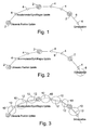
- Figure 1 shows the core problem. Relatively infrequent ultrasonic positional data points 2, are relatively reliable in terms of accuracy. More frequent updates 4 from the other hardware components (accelerometers, gyroscopes and optional magnetometers), which can contribute information to the controller's situation are also available. However, instead of simply knowing the object's position at the positions 2, the problem demands being able to calculate it at many intermediate points on the line 6 which interconnects the points 2 and 4.
- the position and orientation can be tracked, extrapolated beyond the last data input, enhanced when data is received and fed back with a number of corrections to counter drifting and error that is inherent in real hardware applications.
- the methods may be used separately, or preferably, in combination.
- This method allows the estimation of a continuous position (vector P ), and orientation (matrix O) of an article at time T, moveable from an initial situation at time T 0 , described by :
- This method is used to extrapolate the line 6 onwards from the last data input received from the controller. On the diagram, this extrapolation is marked by circle 8. This line represents an estimate of the trajectory of the mobile component which is being tracked.
- T Slice (T - T 0 )/N
- M MatrixCreate( T Slice * R 0 )
- O M 1 x M 2 x M 3 x ....(with N instances of M) .. x O 0
- P P 0 + V (T - T 0 )
- This method allows estimation of a continuous position (vector P ), velocity (vector V ) and orientation (matrix O) of an article at time T, which is between (and including) an initial time T 0 with its situation described by :
- this method is used to amend the preceding motion data when a new batch of accelerometer/gyroscope/magnetometer data comes in. This can be used retrospectively to correct the extrapolation derived in the method described above. Each of the parts of the line marked by circles 10 was established via this method; corrected from their previously extrapolated values which are indicated by broken lines 12.
- This method allows calculation of the situation at time T 1 , which can then be used as the initial conditions (at time T 0 ) for the first method above.
- T Slice (T - T 0 )/N
- R ⁇ Midslice R ⁇ Startslice + R ⁇ Half_inc
- R ⁇ Endslice R ⁇ Midslice + R ⁇ Half_inc
- a ⁇ Midslice A ⁇ Startslice + A ⁇ Half_inc
- a ⁇ Endslice A ⁇ Midslice + A ⁇ Half_inc
- F ⁇ Midslice F ⁇ Startslice + F ⁇ Half_inc
- F ⁇ Endslice F ⁇ Midslice + F ⁇ Midslice + F ⁇ Half_inc
- F True The direction of the true magnetic field F True is known, and we have a direction given by F Midslice that should match it, provided we transform F Midslice back into world space ( it's relative to the controller at present).
- a ⁇ W O midslice ⁇ A ⁇ Midslice ;
- This method uses ultrasonic readings to correct linear velocity estimates, and thus position.
- the dotted path 14 represents the path which was being tracked, complete with its interim corrections 4 from the more frequent accelerometer/gyroscope/magnetometer updates, and even an extrapolation up until the point of our most recent position.
- a new ultrasonic position (vector P) is received at time T.
- vector P the position of the object which are described above.
- This velocity increment propagates through the historical data to the present moment, yielding a current velocity that is increased by the increment and a new calculated P c that exactly matches P .
- This method corrects orientation, and optionally velocity, by taking a plurality of readings from the output of three accelerometers mounted at preferably at 90 degrees to each other and necessarily non-parallel to one another on the article, during transit between the three known positions, assuming that acceleration of the article between the first to the third known positions was substantially constant and verifying this against the plurality of accelerometer readings, calculating the acceleration vector at the second known position using the position and time information about the three known positions and comparing that calculated acceleration vector with the one obtained from the accelerometers (once rotated back into world space from the local space of the article).
- the orientation change to correct vector 18 to match vector 16 is calculated and applied to historical calculations from the time of the second ultrasonic reading 2'''. This reading is chosen because it can be confirmed via former and later ultrasonic readings, whether the assumption of constant accelerations holds true. Therefore the subsequent path of the tracked article can be recalculated with corrected accelerometer readings, from the time of T 2 to the present - see Figure 6 .
- P B P - P 2 Time change between P 1 and P 2
- T A T 2 - T 1 Time change between P and P 1
- T B T - T 1
- the methods typically will be implemented in software with connections to hardware accelerometers, gyroscopes, magnetometers, and ultrasonic transducers.
- the invention encompasses a computer program product, such as downloadable, software, firmware or a physical carrier such as a DVD carrying program steps which when executed on suitable hardware causes the hardware to carry out the steps of the claimed methods.
- the resulting measured motion of the mobile component will be subject to a degree of perturbation as a result of the level of noise and error present in the system.
- These perturbations may be smoothed by a variety of techniques. For example, values may be blended with a proportion of their previous value and a proportion of their new value, yielding a smoothness that takes into account past values whose significance diminishes over time.
- Such a smoothing method can be further refined by making those proportions themselves proportional to the difference between new and old values, thus large differences may force a faster or even instant adoption of the new value, whereas small differences allow a more gradual integration of new values, promoting smoothness. This achieves a system that is both smooth, and responsive to change.
- the user may ascertain where a line through one of the object's axes intersects an arbitrary fixed plane, in effect allowing the object to act as a pointing device.
Landscapes
- Engineering & Computer Science (AREA)
- Radar, Positioning & Navigation (AREA)
- Remote Sensing (AREA)
- Physics & Mathematics (AREA)
- General Physics & Mathematics (AREA)
- Computer Networks & Wireless Communication (AREA)
- Measurement Of Velocity Or Position Using Acoustic Or Ultrasonic Waves (AREA)
- Length Measuring Devices With Unspecified Measuring Means (AREA)
- Automation & Control Theory (AREA)
- Gyroscopes (AREA)
- Ultra Sonic Daignosis Equipment (AREA)
Abstract
Description
- This invention relates to continuous positional and orientational tracking of an object in three dimensions, and optionally, the use of tracking data to control an onscreen pointer.
- There is a desire to be able to accurately and continuously track the position of a handheld controller of the type described in
WO-A-2007/003126 , in conjunction with suitable software. The prior art hardware is limited in that position is given less frequently than desired. For example, a gaming application may require a positional update 60 times a second in view of the expected frame rate of the gaming applications. In practice a typical minimum repeat period for ultrasonic measurements is of the order of 33 to 132ms. Thus there is a need to use other sources of information to accurately fill in the data between these known positions. - In accordance with a first aspect of the invention there is provided a method of estimating position and orientation of an article comprising reading the orientation of the article from three gyroscopes mounted on the article and reading the acceleration of the article from three accelerometers mounted on the article and further comprising estimating a continuous position (vector P), velocity (vector V) and orientation (matrix O) of an article at time T, between T and an initial time T0 where: initial position vector = P 0; initial velocity vector = V 0; initial orientation matrix = O0; initial rotational velocity, relative to the article, vector = R 0; initial acceleration, relative to the article, vector = A 0 and comprising re-calculating (vector P), velocity (vector V) and orientation (matrix O) at a subsequent time T1 using new information from the accelerometers and gyroscopes where: new acceleration relative to the object vector = A 1; new rotational velocity relative to the object vector = R 1; the re-calculation being carried out by, linearly interpolating from R0 to R1 to discover the local rotational velocity at any time between T0 and T1, and by linearly interpolating from A0 to A1 to discover the local acceleration.
- Optionally, the article may further comprise three magnetic sensors mounted therein, the method further comprising estimating a continuous position (vector P), velocity (vector V) and orientation (matrix O) of an article at time T, between T and an initial time To where: initial direction of fixed magnetic field, relative to the article, vector = F 0 (in angular units) and comprising re-calculating (vector P), velocity (vector V) and orientation (matrix O) at a subsequent time T1 using new information from the accelerometers, gyroscopes and magnetometers where: new direction of fixed magnetic field, relative to the article, vector = F 1 (in angular units); the re-calculation being carried out by linearly interpolating from F0 to F1 to discover the local direction of fixed magnetic field.
- According to a second aspect of the invention there is provided a method of estimating position and orientation of an article comprising extrapolating a position (vector P), and orientation (matrix O) of the article at time T, moveable from an initial state at time T0, described by : initial position vector P 0, initial velocity vector V 0, initial orientation matrix O0 (in angular units), and initial rotational velocity, relative to the article, vector R 0, further comprising calculating the duration of a timeslice TSlice = (T - T0)/N, where N tends to zero, making a rotational increment matrix (M) to create a rotation matrix from a rotation expressed as a vector of components representing x, y, and z axes of rotation : M = MatrixCreate( TSlice * R 0), where the estimated orientation and estimated position are given as O = M1 x M2 x M3 x ... x MN x O0 and P = P 0 + V(T - T0) respectively.
- Optionally, either method may further comprise using ultrasonic readings to correct the velocity estimates and thereby estimated position, by modifying the historical velocity estimate when each new ultrasonic reading is received, to make the estimated position match the position given by the new ultrasonic measurement.
- According to a third aspect of the invention there is provided a method of estimating position and orientation of an article comprising correcting orientation, and optionally velocity, by taking a plurality of readings from the output of three accelerometers mounted on the article, using three positions given by ultrasonic time-of-flight measurements, during transit between the first, second and third ultrasonic-derived positions, assuming that acceleration of the article between the first to the third said positions was substantially constant and verifying this against the plurality of accelerometer readings, calculating the acceleration vector at the second said position using the position and time information about the three known positions and comparing that calculated acceleration vector with one obtained from the accelerometers, and thereby re-calibrating the measurements taken from the accelerometers.
- In other aspects, the invention provides a computer program product carrying program steps which when executed on suitable hardware causes the hardware to carry out the steps of the any of the claimed methods and a method of controlling an on-screen pointer, comprising using the position and orientation information of the article derived using any preceding claim, and determining where a line through a predetermined one of the article's axes intersects a plane, which plane may be the plane of the screen.
- Position may be sensed using ultrasonic time-of-flight measurements between fixed and mobile components (such as a handheld games controller), with the readings supplemented by interim readings from accelerometers and gyroscopes. Optionally, magnetometers may be used to provide an absolute directional reference based on the earth's magnetic field or an artificially generated field. The ultrasonic measurement may, for example, be as described in our co-pending
WO-A-2007/003126 , the disclosure of which is incorporated herein by reference. - In taking interim readings from accelerometers and gyroscopes (and optionally magnetometers), it is necessary to ascertain the orientation of the controller in order that the on-board sensors can be interpreted correctly - such orientation knowledge also provides a second application; that of achieving control of an onscreen pointer with the controller.
- In summary, the invention allows determination of complete real-time movement and orientation of a hand-held controller. The system is able to ascertain motion and orientation, provided by preferably 3 orthogonal accelerometers and preferably 3 orthogonal gyroscopes (and optionally magnetometers) respectively, to describe the motion, but with constant feedback/correction from every reliable ultrasonic position received. Thus the subsequent motion is governed by the ultrasonic positions, with the inertial guidance of the accelerometers and gyroscopes filling in the motion for the microseconds in-between ultrasonic position readings.
- The small mismatches between the predicted position, the actual next ultrasonic position, and the extraction of the underlying motion from just ultrasonic readings, are used to calibrate the electronic components of the system, in an attempt to reduce errors to zero. In addition, this live-calibration substantially eliminates linear velocity drift from the accelerometers, and rotational drift from the gyroscopes enabling accurate knowledge of the controller's rotation and thus operation as a pointer. Such feedback also allows complete recovery from any initial conditions or an errored state.
- Embodiments of the invention will now be described by way of example and with reference to the drawings in which:-
-
Figure 1 is a schematic diagram showing the estimation problem, -
Figure 2 is a schematic diagram showing extrapolation of a trajectory, -
Figure 3 is a schematic diagram showing correction of historical extrapolation estimates, -
Figure 4 is a schematic diagram showing correction of historical positional estimates after a velocity correction, -
Figure 5 is a schematic diagram showing calculation of an acceleration vector from three ultrasonic position readings; and -
Figure 6 is a schematic diagram showing recalculated orientation following accelerometer re-calibration. - The term "gyroscope", and derivatives thereof, is used herein to refer to orientation detecting means having a similar function to a gyroscope or gyroscopic sensor. This term is used to include, but is in no means limited to, devices such as gyroscopes; fibre optic gyroscopes; laser gyroscopes; vibrating structure gyroscopes and magnetohydrodynamic sensors. The term is intended to encompass a single such detecting means or group thereof acting jointly or independently. This term is also used to refer to pairs accelerometers arranged to produce similar readings to those of gyroscopes, which may be through an electronic or software interface. In particular, where three gyroscopes are referred to in combination in order to provide rotational information about an article around three non-parallel axes, the skilled man will realise that different gyroscopic sensors may be able to produce the desired information from a greater or smaller number of individual sensors. For example, whilst three vibrating structure gyroscopes may be required to provide complete rotational information in three dimensions, a single "traditional" gyroscope may be able to provide all of this information. Furthermore, the skilled man will realise that while some gyroscopes provide orientation data and others rotational acceleration data, these two data may be interconverted, so allowing the requirements of the invention to be fulfilled.
- A handheld controller or mobile component of the type described in
WO-A-2007/003126 is augmented with sensors able to measure orientation and acceleration in three orthogonal axes such as three, preferably orthogonally mounted, gyroscopes and three, preferably orthogonally mounted, accelerometers. These extra sensors can be polled more rapidly than the ultrasonic measurement system and by tracking relative movement of the controller, allow interpolation and extrapolation of the ultrasonic measurements of position and also allow orientation of the controller to be measured. The gyroscopes may be supplemented with magnetometers to further improve orientation sensing. - The system seeks to calculate substantially continuous position and orientation of an object such as a handheld games controller or pointer, here referred to as "mobile component" from the following discrete information:
- Approximate position of a mobile component every 33-132ms, by triangulating the times of flight of an ultrasonic pulse travelling from the component to 3 or more sensors of known position, separated by 20cm or more from each other.
- Approximate resultant acceleration of the mobile component, every 11ms, by reading 3 accelerometers attached to the mobile component and oriented at preferably at 90 degrees to each other and necessarily non-parallel to one another. This acceleration is relative to the mobile component, because the accelerometers are mounted on the component itself.
- Approximate rotational velocity of the component, every 11ms, by reading 3 gyroscopes mounted to the mobile component preferably at 90 degrees to each other and necessarily non-parallel to one another. This rotational velocity is relative to the component, because the gyroscopes are mounted on the component itself.
- Optionally, the rotational offset of the mobile component from the vector of the local magnetic field, whether it is that of the Earth, or artificially induced, every 11ms, by reading 3 magnetometers preferably at 90 degrees to each other and necessarily non-parallel to one another, again mounted on the component.
- It will be appreciated that all the values above are necessarily approximate because the hardware will be affected by noise, and may also suffer from errors in alignment, or errors from incorrect centring and calibration. It is therefore preferable that the method described below is robust and stable, even given the imprecise nature of its inputs.
- In addition, the method is preferably able to recover from a complete absence of data, and return rapidly to the correct position and orientation.
- The method also allows any data that is assessed to be unreliable to be disregarded without undue error or instability.
-
Figure 1 shows the core problem. Relatively infrequent ultrasonicpositional data points 2, are relatively reliable in terms of accuracy. Morefrequent updates 4 from the other hardware components (accelerometers, gyroscopes and optional magnetometers), which can contribute information to the controller's situation are also available. However, instead of simply knowing the object's position at thepositions 2, the problem demands being able to calculate it at many intermediate points on theline 6 which interconnects thepoints - Using the methods described below, the position and orientation can be tracked, extrapolated beyond the last data input, enhanced when data is received and fed back with a number of corrections to counter drifting and error that is inherent in real hardware applications. The methods may be used separately, or preferably, in combination.
- This method allows the estimation of a continuous position (vector P), and orientation (matrix O) of an article at time T, moveable from an initial situation at time T0, described by :
- 1. position, (vector P 0 in metres)
- 2. velocity, (vector V 0 in metres/second)
- 3. orientation (matrix O 0 in radians)
- 4. rotational velocity relative to the object (vector R 0 in radians/second)
- With reference to
Figure 2 , This method is used to extrapolate theline 6 onwards from the last data input received from the controller. On the diagram, this extrapolation is marked bycircle 8. This line represents an estimate of the trajectory of the mobile component which is being tracked. - This method is now described in more detail.
- Initially we assume zero linear and rotational acceleration over the intervening time between T0 and T. However, this method may be extended to accommodate these initial acceleration values being non-zero.
- For simplicity, we detail updating of the orientation, by incrementing in small time slices. The smaller the slices are made, the more accurate the method becomes and, ultimately mathematical integration may be used as the size of time slice tends to zero if needed. We choose to subdivide the time period (T-T0) into N time slices, where, in a preferred embodiment, N is a chosen whole number giving each time slice a duration of approximately 10microseconds.
- Duration of the timeslice is calculated : TSlice = (T - T0)/N
Make a rotational increment matrix (M) using a standard function (MatrixCreate) such as the Microsoft DirectX 9 function D3DXMatrixRotationYawPitchRoll, to create a rotation matrix from a rotation expressed as a vector of components representing x, y, and z axes of rotation : M = MatrixCreate( TSlice * R 0)
O = M1 x M2 x M3 x ....(with N instances of M) .. x O0
P = P 0 + V(T - T0) - This provides a representation of an extrapolated portion of the
line 8 which may be fed back to an application seeking positional information since the last accelerometer/gyroscope/magnetometer reading 4. - This method allows estimation of a continuous position (vector P), velocity (vector V) and orientation (matrix O) of an article at time T, which is between (and including) an initial time T0 with its situation described by :
- 1. position, (vector P 0 in metres)
- 2. velocity, (vector V 0 in metres/second)
- 3. orientation (matrix O0 in radians)
- 4. rotational velocity relative to the object (vector R 0 in radians/second)
- 5. acceleration relative to the object (vector A 0 in metres/second2)
- 6. optional direction of fixed magnetic field, relative to the object (vector F 0 in radians)
and a subsequent time T1 at which time the following additional information becomes known, by virtue of new data from the accelerometers, gyroscopes and magnetometers : - 1. acceleration relative to the object (vector A 1 in metres/second2)
- 2. rotational velocity relative to the object (vector R 1 in radians/second)
- 3. direction of fixed magnetic field, relative to the object (vector F 1 in radians)
- With reference to
Figure 3 , this method is used to amend the preceding motion data when a new batch of accelerometer/gyroscope/magnetometer data comes in. This can be used retrospectively to correct the extrapolation derived in the method described above. Each of the parts of the line marked bycircles 10 was established via this method; corrected from their previously extrapolated values which are indicated bybroken lines 12. - This method allows calculation of the situation at time T1, which can then be used as the initial conditions (at time T0) for the first method above.
- This method is now described in detail.
- Again for simplicity, we consider updates over a small timeslice. Again we choose to subdivide the time period (T-T0) into N time slices, where N is a whole number typically giving each time slice a duration of approximately 10microseconds.
- From R0 and R1, we linearly interpolate to discover the local (relative to object) rotational velocity at any time between T0 and T1. Similarly we linearly interpolate the local acceleration, and direction of fixed magnetic field.
- We iterate through the N time slices. In practice this is desirable in order to save out historical data, for processing by the end application of the controller. For each time-slice one can see that the initial data is available from the initial conditions for the first one, and then subsequently from the endpoint of the prior time-slice.
- Duration of the time-slice is calculated : TSlice = (T - T0)/N
- Increment rotation velocity per half slice : R Half_inc = ¼ * (R 0 + R 1) * TSlice;
- Increment acceleration per half slice : A Half_inc = ¼ * (R 0 + R 1) * TSlice;
- Increment magnetic field per half slice : F Half_inc = ¼ * (F 0 + F 1) * TSlice;
- So, for each of N time-slices :
- (We preferably use values in the middle of the time-slices as the best representation of the values across the whole time-slice.)


- Increment rotational matrix for half a time slice : M = MatrixCreate(R Midslice)

- The direction of the true magnetic field F True is known, and we have a direction given by F Midslice that should match it, provided we transform F Midslice back into world space ( it's relative to the controller at present).
- Hence we rotate OMidslice by the shortest rotation such that (OMidlice -1 * F Midslice) is aligned with F True;

- Similarly we correct OEndslice by reference to rotating by the shortest rotation such that (OMidslice -1 * F Endshce) is aligned with F True;
- Now calculate average world acceleration A W for this slice from the averages.

- So use this acceleration in the equations of motion for this slice.


- Finally, we read off the values from the end of Nth slice to give us P, V, and O.
- This method uses ultrasonic readings to correct linear velocity estimates, and thus position.
- Every time a new ultrasonic reading is received, it is treated as the correct location, and the historical velocity estimate of the object is modified in such a way that the tracked position becomes correct at this point in time.
- With reference to
Figure 4 , thedotted path 14 represents the path which was being tracked, complete with itsinterim corrections 4 from the more frequent accelerometer/gyroscope/magnetometer updates, and even an extrapolation up until the point of our most recent position. Now, when the ultrasonic position 2' is received, we adjust the velocity at the time of the lastultrasonic reading 2", such that the subsequent motion puts our tracked position at exactly the position the ultrasonics are now telling us. As a consequence of this velocity correction, we will see that the position is also corrected and the assumed positions of the accelerometer/gyroscope/magnetometer updates are adjusted to new positions 4-1. - The method is now described in more detail.
- A new ultrasonic position (vector P), is received at time T.
Using the methods of tracking the object which are described above, we calculate our position to be vector P c. - Historically, we received our last ultrasonic position at time T0, and since we are using this method where calculated and ultrasonic positions are synchronised, we can assume that this was the case at time T0.
- Therefore in time (T-T0), our position has deviated by (P c -P), and we calculate the extra velocity we should have had since time T0 in order for that deviation to be zero.

- This velocity increment propagates through the historical data to the present moment, yielding a current velocity that is increased by the increment and a new calculated P c that exactly matches P.
- Because it is a velocity change, the position curve remains continuous. However, it can be noted that there will be a step/discontinuity in the velocity at time T0, which could be post-processed if continuity is required in the historical velocity data, as well as smoothness in the historical position data.
- This method corrects orientation, and optionally velocity, by taking a plurality of readings from the output of three accelerometers mounted at preferably at 90 degrees to each other and necessarily non-parallel to one another on the article, during transit between the three known positions, assuming that acceleration of the article between the first to the third known positions was substantially constant and verifying this against the plurality of accelerometer readings, calculating the acceleration vector at the second known position using the position and time information about the three known positions and comparing that calculated acceleration vector with the one obtained from the accelerometers (once rotated back into world space from the local space of the article).
- With reference to
Figure 5 ,3 ultrasonic positions 2 are given with their associated times. Anacceleration vector 16 is calculated from that data, and an estimatedvector 18 is based on accelerometer readings. Anorientation correction 20 is then given to align these twovectors - The orientation change to correct
vector 18 to matchvector 16 is calculated and applied to historical calculations from the time of the second ultrasonic reading 2'''. This reading is chosen because it can be confirmed via former and later ultrasonic readings, whether the assumption of constant accelerations holds true. Therefore the subsequent path of the tracked article can be recalculated with corrected accelerometer readings, from the time of T2 to the present - seeFigure 6 . - From our calculations, we can also ascertain velocity at time T2, which can be optionally fed into the calculations.
- This method is now described in more detail.
- Firstly we calculate the acceleration and velocity at T2, using formulae derived from simultaneous equations of linear motion and the position vectors P 1, P 2 and P, and the times T1, T2, and T.
- Position change between P 1 and P 2, P A = P 2 - P 1
Position change between P and P 1, PB = P - P 2
Time change between P 1 and P 2, TA = T2 - T1
Time change between P and P 1, TB = T - T1
Then acceleration at T2, A2 = (2 * ((TA * P B) - (TB * P A)))/(TA * TB * (TA + TB))
And velocity at T2, V2 = (P A/TA) + (1/2 * A2 * TA) - Next we look at the accelerometer readings from time T2, to give us the acceleration in the local frame of the controller, which must then be rotated by the inverse of the orientation matrix we have at that time. Thus we get A2accel.
- We compare the magnitudes of A2 and A2accel, to check they are consistent, i.e. say within 10%.
- If so, then we adjust the orientation at time T2 to align A2accel with A2.
Optionally we may also choose to set the velocity at time T2 to V2.
Then recalculate our article's situation over the time, re-feeding in the inputs between T2 and current time T, to arrive at a corrected history and current situation of the article. - It will be understood that preferably, and for maximum accuracy of estimates, these various methods are used together. However, they may be used separately, or alternatively in different combinations with each other.
- The methods typically will be implemented in software with connections to hardware accelerometers, gyroscopes, magnetometers, and ultrasonic transducers. Thus the invention encompasses a computer program product, such as downloadable, software, firmware or a physical carrier such as a DVD carrying program steps which when executed on suitable hardware causes the hardware to carry out the steps of the claimed methods.
- The resulting measured motion of the mobile component will be subject to a degree of perturbation as a result of the level of noise and error present in the system. These perturbations may be smoothed by a variety of techniques. For example, values may be blended with a proportion of their previous value and a proportion of their new value, yielding a smoothness that takes into account past values whose significance diminishes over time. Such a smoothing method can be further refined by making those proportions themselves proportional to the difference between new and old values, thus large differences may force a faster or even instant adoption of the new value, whereas small differences allow a more gradual integration of new values, promoting smoothness. This achieves a system that is both smooth, and responsive to change.
- Since the complete motion and orientation of the object is described, the user may ascertain where a line through one of the object's axes intersects an arbitrary fixed plane, in effect allowing the object to act as a pointing device.
Claims (7)
- A method of estimating position and orientation of an article comprising reading the orientation of the article from three gyroscopes mounted on the article and reading the acceleration of the article from three accelerometers mounted on the article and further comprising estimating a continuous position (vector P), velocity (vector V) and orientation (matrix O) of an article at time T, between T and an initial time T0 where:initial position vector = P 0initial velocity vector = V 0initial orientation matrix = O0initial rotational velocity, relative to the article, vector = R 0initial acceleration, relative to the article, vector = A 0
and comprising re-calculating (vector P), velocity (vector V) and orientation (matrix O) at a subsequent time T1 using new information from the accelerometers and gyroscopes where:new acceleration relative to the object vector = A 1new rotational velocity relative to the object vector = R 1
the re-calculation being carried out by, linearly interpolating from R0 to R1 to discover the local rotational velocity at any time between T0 and T1, and by linearly interpolating from A0 to A1 to discover the local acceleration. - A method according to claim 1, the article further comprising three magnetic sensors mounted therein, the method further comprising estimating a continuous position (vector P), velocity (vector V) and orientation (matrix O) of an article at time T, between T and an initial time T0 where:initial direction of fixed magnetic field, relative to the article, vector = F 0 (in angular units)
and comprising re-calculating (vector P), velocity (vector V) and orientation (matrix O) at a subsequent time T1 using new information from the accelerometers, gyroscopes and magnetometers where: new direction of fixed magnetic field, relative to the article, vector = F 1 (in angular units)the re-calculation being carried out by linearly interpolating from F0 to F1 to discover the local direction of fixed magnetic field. - A method of estimating position and orientation of an article comprising extrapolating a position (vector P), and orientation (matrix O) of the article at time T, moveable from an initial state at time T0, described by :initial position vector P 0, initial velocity vector V 0, initial orientation matrix O0 (in angular units), and initial rotational velocity, relative to the article, vector R 0, further comprising calculating the duration of a timeslice TSlice = (T - T0)/N, where N tends to zero, making a rotational increment matrix (M) to create a rotation matrix from a rotation expressed as a vector of components representing x, y, and z axes of rotation : M = MatrixCreate( TSlice * R 0), where the estimated orientation and estimated position are given as O = M1 x M2 x M3 x ... x MN x O0 and P = P 0 + V(T - T0) respectively.
- A method according to claim 1, 2 or 3, comprising using ultrasonic readings to correct the velocity estimates and thereby estimated position, by modifying the historical velocity estimate when each new ultrasonic reading is received, to make the estimated position match the position given by the new ultrasonic measurement.
- A method of estimating position and orientation of an article comprising correcting orientation, and optionally velocity, by taking a plurality of readings from the output of three accelerometers mounted on the article, using three positions given by ultrasonic time-of-flight measurements, during transit between the first, second and third ultrasonic-derived positions, assuming that acceleration of the article between the first to the third said positions was substantially constant and verifying this against the plurality of accelerometer readings, calculating the acceleration vector at the second said position using the position and time information about the three known positions and comparing that calculated acceleration vector with one obtained from the accelerometers, and thereby re-calibrating the measurements taken from the accelerometers.
- A computer program product carrying program steps which when executed on suitable hardware causes the hardware to carry out the steps of the any of the claimed methods.
- A method of controlling an on-screen pointer, comprising using the position and orientation information of the article derived using any preceding claim, and determining where a line through a predetermined one of the article's axes intersects a plane.
Applications Claiming Priority (2)
| Application Number | Priority Date | Filing Date | Title |
|---|---|---|---|
| GBGB0808081.4A GB0808081D0 (en) | 2008-05-02 | 2008-05-02 | Bridging ultrasonic position with accelerometer/gyroscope inertial guidance |
| GB0812533A GB2459718A (en) | 2008-05-02 | 2008-07-09 | Motion smoothing in 3D position sensing apparatus |
Publications (2)
| Publication Number | Publication Date |
|---|---|
| EP2113745A2 true EP2113745A2 (en) | 2009-11-04 |
| EP2113745A3 EP2113745A3 (en) | 2009-12-16 |
Family
ID=39537236
Family Applications (1)
| Application Number | Title | Priority Date | Filing Date |
|---|---|---|---|
| EP09156865A Withdrawn EP2113745A3 (en) | 2008-05-02 | 2009-03-31 | Motion smoothing in 3-D position sensing apparatus |
Country Status (4)
| Country | Link |
|---|---|
| US (1) | US8868368B2 (en) |
| EP (1) | EP2113745A3 (en) |
| GB (2) | GB0808081D0 (en) |
| WO (1) | WO2009133338A2 (en) |
Families Citing this family (18)
| Publication number | Priority date | Publication date | Assignee | Title |
|---|---|---|---|---|
| US9590733B2 (en) | 2009-07-24 | 2017-03-07 | Corning Optical Communications LLC | Location tracking using fiber optic array cables and related systems and methods |
| EP2553839A1 (en) | 2010-03-31 | 2013-02-06 | Corning Cable Systems LLC | Localization services in optical fiber-based distributed communications components and systems, and related methods |
| US8570914B2 (en) | 2010-08-09 | 2013-10-29 | Corning Cable Systems Llc | Apparatuses, systems, and methods for determining location of a mobile device(s) in a distributed antenna system(s) |
| CN102052921B (en) * | 2010-11-19 | 2012-08-22 | 哈尔滨工程大学 | Method for determining initial heading of single-axis rotating strapdown inertial navigation system |
| JP5459678B2 (en) * | 2011-02-17 | 2014-04-02 | 株式会社東芝 | Mobile image tracking device |
| US9279680B2 (en) * | 2012-03-15 | 2016-03-08 | Blackberry Limited | Methods and devices for determining orientation |
| US9781553B2 (en) | 2012-04-24 | 2017-10-03 | Corning Optical Communications LLC | Location based services in a distributed communication system, and related components and methods |
| US10215587B2 (en) | 2012-05-18 | 2019-02-26 | Trx Systems, Inc. | Method for step detection and gait direction estimation |
| WO2013181247A1 (en) | 2012-05-29 | 2013-12-05 | Corning Cable Systems Llc | Ultrasound-based localization of client devices with inertial navigation supplement in distributed communication systems and related devices and methods |
| WO2013188597A2 (en) | 2012-06-12 | 2013-12-19 | Amrit Bandyopadhyay | Irregular feature mapping |
| US9158864B2 (en) | 2012-12-21 | 2015-10-13 | Corning Optical Communications Wireless Ltd | Systems, methods, and devices for documenting a location of installed equipment |
| WO2014176033A1 (en) * | 2013-04-25 | 2014-10-30 | Corning Optical Communications LLC | Ultrasound-based location determination and inertial navigation with accuracy improvement in determining client device location |
| US10172443B2 (en) * | 2013-08-11 | 2019-01-08 | Yong-Jing Wang | Oral care tools and systems |
| US10563981B1 (en) * | 2013-08-22 | 2020-02-18 | Moov Inc. | Automated motion data processing |
| US9648580B1 (en) | 2016-03-23 | 2017-05-09 | Corning Optical Communications Wireless Ltd | Identifying remote units in a wireless distribution system (WDS) based on assigned unique temporal delay patterns |
| TWI700614B (en) | 2017-04-21 | 2020-08-01 | 宏達國際電子股份有限公司 | Operating method of tracking system, controller, tracking system, and non-transitory computer readable storage medium |
| EP3540463B1 (en) * | 2018-03-09 | 2022-06-01 | Tata Consultancy Services Limited | Radar and ultrasound sensor based real time tracking of a moving object |
| CN110108902B (en) * | 2019-05-23 | 2021-02-02 | 电子科技大学 | Measurement error correction method for three-dimensional non-orthogonal ultrasonic array wind measuring device |
Citations (1)
| Publication number | Priority date | Publication date | Assignee | Title |
|---|---|---|---|---|
| WO2007003126A1 (en) | 2005-07-02 | 2007-01-11 | Huawei Technologies Co., Ltd. | Method for transmitting short data during group call in wireless communication system |
Family Cites Families (21)
| Publication number | Priority date | Publication date | Assignee | Title |
|---|---|---|---|---|
| US3301508A (en) * | 1961-06-07 | 1967-01-31 | United Aircraft Corp | Guidance system with stellar correction |
| JPH07104145B2 (en) * | 1989-10-11 | 1995-11-13 | 株式会社ミツトヨ | Output timing interpolation method for position detection device |
| US5229551A (en) * | 1991-11-04 | 1993-07-20 | Summagraphics Corporation | Hysteresis compensation for a digitizer tablet |
| IL122578A (en) * | 1997-12-12 | 2000-08-13 | Super Dimension Ltd | Wireless six-degree-of-freedom locator |
| US6176837B1 (en) * | 1998-04-17 | 2001-01-23 | Massachusetts Institute Of Technology | Motion tracking system |
| JP2000078614A (en) * | 1998-09-02 | 2000-03-14 | Sony Corp | Picture recording device |
| US6516213B1 (en) * | 1999-09-03 | 2003-02-04 | Robin Medical, Inc. | Method and apparatus to estimate location and orientation of objects during magnetic resonance imaging |
| US6823602B2 (en) * | 2001-02-23 | 2004-11-30 | University Technologies International Inc. | Continuous measurement-while-drilling surveying |
| US6895678B2 (en) * | 2002-08-01 | 2005-05-24 | The Charles Stark Draper Laboratory, Inc. | Borehole navigation system |
| WO2004056425A2 (en) * | 2002-12-19 | 2004-07-08 | Fortescue Corporation | Method and apparatus for determining orientation and position of a moveable object |
| US7028546B2 (en) * | 2003-10-21 | 2006-04-18 | Instrumented Sensor Technology, Inc. | Data recorder |
| WO2005108119A2 (en) * | 2004-04-30 | 2005-11-17 | Hillcrest Laboratories, Inc. | Free space pointing devices with tilt compensation and improved usability |
| IL165314A (en) * | 2004-11-21 | 2009-08-03 | Elbit Ltd | Electromagnetic tracker |
| JP4426432B2 (en) * | 2004-12-17 | 2010-03-03 | 本田技研工業株式会社 | Auxiliary moment control method for leg exercise assistive device |
| EP1872087A4 (en) * | 2005-04-19 | 2012-10-17 | Jaymart Sensors Llc | Miniaturized inertial measurement unit and associated methods |
| JP2007041733A (en) * | 2005-08-01 | 2007-02-15 | Toyota Motor Corp | Attitude angle detection device for motion object |
| US20070113652A1 (en) * | 2005-10-07 | 2007-05-24 | Renken Wayne G | Wireless Position Sensing Wafer |
| KR101185144B1 (en) * | 2006-01-24 | 2012-09-24 | 삼성전자주식회사 | Method and apparatus for estimating 2-dimension trajectory of a gesture |
| KR100711261B1 (en) * | 2006-06-21 | 2007-04-25 | (주)마이크로인피니티 | Method for recognizing space of inputting device and apparatus thereof |
| US7826999B1 (en) * | 2007-08-20 | 2010-11-02 | Pni Corporation | Magnetic tilt compensated heading compass with adaptive zoffset |
| KR101472842B1 (en) * | 2007-09-11 | 2014-12-16 | 삼성전자 주식회사 | Apparatus and method for recognizing moving signal |
-
2008
- 2008-05-02 GB GBGB0808081.4A patent/GB0808081D0/en not_active Ceased
- 2008-07-09 GB GB0812533A patent/GB2459718A/en not_active Withdrawn
-
2009
- 2009-03-31 EP EP09156865A patent/EP2113745A3/en not_active Withdrawn
- 2009-04-02 WO PCT/GB2009/000873 patent/WO2009133338A2/en active Application Filing
-
2010
- 2010-09-13 US US12/881,093 patent/US8868368B2/en not_active Expired - Fee Related
Patent Citations (1)
| Publication number | Priority date | Publication date | Assignee | Title |
|---|---|---|---|---|
| WO2007003126A1 (en) | 2005-07-02 | 2007-01-11 | Huawei Technologies Co., Ltd. | Method for transmitting short data during group call in wireless communication system |
Also Published As
| Publication number | Publication date |
|---|---|
| WO2009133338A2 (en) | 2009-11-05 |
| GB0812533D0 (en) | 2008-08-13 |
| US8868368B2 (en) | 2014-10-21 |
| GB2459718A (en) | 2009-11-04 |
| EP2113745A3 (en) | 2009-12-16 |
| GB0808081D0 (en) | 2008-06-11 |
| US20110071785A1 (en) | 2011-03-24 |
| WO2009133338A3 (en) | 2010-12-02 |
Similar Documents
| Publication | Publication Date | Title |
|---|---|---|
| US8868368B2 (en) | Motion smoothing in 3-D position sensing apparatus | |
| US10323501B2 (en) | Method and apparatus for generating weighted average survey | |
| JP6094026B2 (en) | Posture determination method, position calculation method, and posture determination apparatus | |
| US6409687B1 (en) | Motion tracking system | |
| JP4199553B2 (en) | Hybrid navigation device | |
| EP2583059B1 (en) | Improved north finder | |
| EP2901104B1 (en) | Improved inertial navigation system and method | |
| EP1983304B1 (en) | Heading stabilization for aided inertial navigation systems | |
| EP3645836A1 (en) | System and method for generating output of a downhole inertial measurement unit | |
| US6381858B1 (en) | Method for calculating gyroscopic wellbore surveys including correction for unexpected instrument movement | |
| CN108731664B (en) | Robot state estimation method, device, computer equipment and storage medium | |
| JPH0328714A (en) | Measuring and control system for sensor scanning | |
| JP4729197B2 (en) | Object posture detection apparatus and integer bias redetermination method | |
| CN107747953A (en) | A kind of multi-sensor data and orbit information method for synchronizing time | |
| US6588117B1 (en) | Apparatus with gyroscopes and accelerometers for determining the attitudes of an aerodyne | |
| JP6383907B2 (en) | Vehicle position measuring apparatus and method | |
| JP5022747B2 (en) | Mobile body posture and orientation detection device | |
| JP2018052489A (en) | System and method for compensating for absence of sensor measurement in heading measuring system | |
| RU2539131C1 (en) | Strapdown integrated navigation system of average accuracy for mobile onshore objects | |
| JP4343581B2 (en) | Moving body posture detection device | |
| JP2015004593A (en) | Navigation device | |
| KR101140379B1 (en) | Method and apparatus for estimating orientation by using lie algebra and kalman filter | |
| RU2754396C1 (en) | Adaptive method for correcting orientation angles of strapdown ins | |
| JP2016109609A (en) | Posture estimation device and control program for posture estimation device | |
| Ailneni et al. | Characterization of MEMS based inertial measurement unit |
Legal Events
| Date | Code | Title | Description |
|---|---|---|---|
| PUAI | Public reference made under article 153(3) epc to a published international application that has entered the european phase |
Free format text: ORIGINAL CODE: 0009012 |
|
| AK | Designated contracting states |
Kind code of ref document: A2 Designated state(s): AT BE BG CH CY CZ DE DK EE ES FI FR GB GR HR HU IE IS IT LI LT LU LV MC MK MT NL NO PL PT RO SE SI SK TR |
|
| AX | Request for extension of the european patent |
Extension state: AL BA RS |
|
| PUAL | Search report despatched |
Free format text: ORIGINAL CODE: 0009013 |
|
| AK | Designated contracting states |
Kind code of ref document: A3 Designated state(s): AT BE BG CH CY CZ DE DK EE ES FI FR GB GR HR HU IE IS IT LI LT LU LV MC MK MT NL NO PL PT RO SE SI SK TR |
|
| AX | Request for extension of the european patent |
Extension state: AL BA RS |
|
| AKY | No designation fees paid | ||
| REG | Reference to a national code |
Ref country code: DE Ref legal event code: 8566 |
|
| STAA | Information on the status of an ep patent application or granted ep patent |
Free format text: STATUS: THE APPLICATION IS DEEMED TO BE WITHDRAWN |
|
| 18D | Application deemed to be withdrawn |
Effective date: 20100617 |