JP4426432B2 - Auxiliary moment control method for leg exercise assistive device - Google Patents
Auxiliary moment control method for leg exercise assistive device Download PDFInfo
- Publication number
- JP4426432B2 JP4426432B2 JP2004366911A JP2004366911A JP4426432B2 JP 4426432 B2 JP4426432 B2 JP 4426432B2 JP 2004366911 A JP2004366911 A JP 2004366911A JP 2004366911 A JP2004366911 A JP 2004366911A JP 4426432 B2 JP4426432 B2 JP 4426432B2
- Authority
- JP
- Japan
- Prior art keywords
- leg
- joint
- orthosis
- reaction force
- floor reaction
- Prior art date
- Legal status (The legal status is an assumption and is not a legal conclusion. Google has not performed a legal analysis and makes no representation as to the accuracy of the status listed.)
- Expired - Fee Related
Links
Images


Classifications
-
- A—HUMAN NECESSITIES
- A61—MEDICAL OR VETERINARY SCIENCE; HYGIENE
- A61F—FILTERS IMPLANTABLE INTO BLOOD VESSELS; PROSTHESES; DEVICES PROVIDING PATENCY TO, OR PREVENTING COLLAPSING OF, TUBULAR STRUCTURES OF THE BODY, e.g. STENTS; ORTHOPAEDIC, NURSING OR CONTRACEPTIVE DEVICES; FOMENTATION; TREATMENT OR PROTECTION OF EYES OR EARS; BANDAGES, DRESSINGS OR ABSORBENT PADS; FIRST-AID KITS
- A61F5/00—Orthopaedic methods or devices for non-surgical treatment of bones or joints; Nursing devices; Anti-rape devices
- A61F5/01—Orthopaedic devices, e.g. splints, casts or braces
- A61F5/0102—Orthopaedic devices, e.g. splints, casts or braces specially adapted for correcting deformities of the limbs or for supporting them; Ortheses, e.g. with articulations
Landscapes
- Health & Medical Sciences (AREA)
- Vascular Medicine (AREA)
- Orthopedic Medicine & Surgery (AREA)
- Engineering & Computer Science (AREA)
- Biomedical Technology (AREA)
- Heart & Thoracic Surgery (AREA)
- Nursing (AREA)
- Life Sciences & Earth Sciences (AREA)
- Animal Behavior & Ethology (AREA)
- General Health & Medical Sciences (AREA)
- Public Health (AREA)
- Veterinary Medicine (AREA)
- Rehabilitation Tools (AREA)
- Manipulator (AREA)
Description
本発明は、人の脚体の運動(歩行など)を補助するために該人に装着される脚体運動補助装具の補助モーメント制御方法に関する。 The present invention relates to an auxiliary moment control method for a leg exercise assisting device worn on a person in order to assist a person's leg movement (such as walking).
従来、この種の脚体運動補助装具としては、例えば特許文献1に見られるものが知られている。この特許文献1のものの補助装具は、人の腰部に装着される腰支持ベルトと、人の各足平部を載せる足支持部とを、腰部側から順に、股関節に対応する腰部モーメント発生装置、大腿部に対応する大腿支持ビーム、膝関節に対応する膝部モーメント発生装置、下腿部に対応する脛支持ビーム、足首関節に対応する踝部モーメント発生部を介して連結すると共に、足支持部、脛支持ビーム、大腿支持ビームをそれぞれベルトにより人の脚体の足平部、下腿部、大腿部に接続している。そして、足支持部の底部に備えた荷重センサと各ベルトに備えた力センサとの検出値から人の各脚体に作用する外力を計算し、その計算した外力を基に、人の脚体の各関節に発生するモーメントを計算するようにしている。さらに、その計算したモーメントに所定の軽減率を掛けて目標モーメントを決定し、その目標モーメントを満足し得る力が補助装具から人の脚体に作用するように各モーメント発生装置を制御するようにしている。
ところで、人に装着される脚体運動補助装具は、人が該補助装具の重さや該補助装具の運動によって発生する慣性力を感じることなく、人の脚体の運動を補助できるものであることが望まれる。例えば、補助装具から脚体の各関節に付与すべき目標補助モーメントを0とした場合に、補助装具を装着していない場合と同じように、人の脚体の運動を行なえることが望ましい。つまり、目標補助モーメントを0とした場合に、補助装具は、人が意識的に該補助装具の各部を動かす力を発生させることなく、自律的に(単独で)、人の脚体の運動に追従するように運動できることが望ましい。そして、その上で、人が補助装具を装着していない場合に該人が想定している脚体の所望の運動を行なうために動力学的に必要となる脚体の関節のモーメントの一部を補助装具によって負担できるようにすることが望ましい。 By the way, the leg exercise assistive device worn by a person can assist the movement of the human leg without the person feeling the weight of the assistive device or the inertial force generated by the exercise of the assistive device. Is desired. For example, when the target assist moment to be applied to each joint of the leg from the assisting device is set to 0, it is desirable that the human leg can be exercised as in the case where the assisting device is not worn. In other words, when the target auxiliary moment is set to 0, the auxiliary device autonomously (independently) moves the human leg without generating a force for the person to consciously move each part of the auxiliary device. It is desirable to be able to exercise to follow. In addition, when a person does not wear the auxiliary equipment, a part of the moment of the joint of the leg that is dynamically required to perform the desired movement of the leg assumed by the person It is desirable to be able to bear the burden with an auxiliary brace.
しかしながら、前記特許文献1のものでは、補助装具が人の脚体の運動に自律的に追従する上で必要となる補助装具1への外力や、該補助装具の関節のモーメントが考慮されていない。このため、特許文献1のものでは、人の移動時の多くの状況において、人が該補助装具の重さや該補助装具の運動によって発生する慣性力(補助力以外の慣性力)受ける。そのため、補助装具を装着した人は、その補助装具の重さ等を意識しながら脚体を運動させなければならない状況が多々ある。その結果、脚体の実際の運動パターンと人が想定した運動パターンとのずれを生じやすく、ひいては、脚体の運動がぎくしゃくしたり、脚体の運動を円滑に行うこと困難となるという不都合があった。
However, the thing of the said
また、特許文献1のものでは、足支持部の底面や、人の脚体に固定するバンドに多数の力センサを設けているため、コスト的に不利であると共に、各力センサの出力に含まれるノイズの影響を相乗的に受けやすいという不都合もあった。特に、足支持部の底面の荷重センサの出力は、床形状等の影響を直接的に受けやすいと共に、衝撃による損傷も生じやすいために、高い信頼性を確保することが困難である。その結果、補助装具のモーメント発生装置で発生するモーメントの乱れが生じやすく、人の脚体に作用させる補助力が急変したりする恐れがあった。
Moreover, in the thing of
本発明はかかる背景に鑑みてなされたものであり、人に装着する脚体運動補助装具の重さなど、人の脚体の運動を補助するために必要な力以外の力が人に作用するのを効果的に低減し、できるだけ脚体運動補助装具が装着されていなような感覚で人が脚体の運動を行うことを可能とする脚体運動補助装具の補助モーメント制御方法を提供することを目的とする。また、脚体運動補助装具の足平装着部の底面に力センサを備えたりすることなく、人の該補助装具の回転力発生手段に適切な回転力を発生させるように該回転力発生手段を制御できる脚体運動補助装具の補助モーメント制御方法を提供することを目的とする。 The present invention has been made in view of such a background, and a force other than the force necessary to assist the movement of the human leg, such as the weight of the leg exercise assisting device worn on the person, acts on the person. To provide a method for controlling an auxiliary moment of a leg exercise assisting device that enables a person to exercise the leg with a sense that the leg exercise assistive device is not worn as much as possible. With the goal. Further, the rotational force generating means is provided so as to generate an appropriate rotational force to the rotational force generating means of the human auxiliary device without providing a force sensor on the bottom surface of the foot mounting portion of the leg exercise auxiliary device. It is an object of the present invention to provide an auxiliary moment control method for a leg exercise assistive device that can be controlled.
本発明の脚体運動補助装具の補助モーメント制御方法の第1発明は、前記の目的を達成するために、
人の腰部に固定された腰装着部と、人の各足平部にそれぞれ固定され、該足平部の着地期に人の重量を受けつつ接地するように設けられた一対の足平装着部と、前記腰装着部と各足平装着部とをそれぞれ連結して、該腰装着部と各足平装着部との間で人の各脚体に概略沿うように延在する一対の脚リンク部とを少なくとも備えると共に、各脚リンク部に、人の股関節、膝関節および足首関節にそれぞれ対応する3つの関節部位を少なくとも含む複数の関節部位と、該複数の関節部位のうちの少なくとも股関節および膝関節に対応する関節部位に回転力を発生可能な回転力発生手段とを備えた脚体運動補助装具に対し、該回転力発生手段に発生させる回転力を制御する方法であって、
前記脚体運動補助装具を装着した人の両脚体の運動が行なわれている時に、
該人の両脚体の運動が脚体運動補助装具を人から取り外して行なわれているとした場合に各脚体の膝関節および股関節にそれぞれ発生すべきモーメントである人側関節モーメントを逐次推定する第1ステップと、
該人の両脚体の運動に伴う脚体運動補助装具の運動を該脚体運動補助装具が単独で行なっているとした場合に該脚体運動補助装具の各足平装着部に作用する床反力を逐次推定する第2ステップと、
前記脚体運動補助装具の各脚リンク部が該脚リンク部に連結された足平装着部を介して人から受ける力と、該人の両脚体の運動に伴う脚体運動補助装具の運動を該脚体運動補助装具が単独で行なっているとした場合に該足平装着部が受ける床反力との合力を検出可能に、各脚リンク部の膝関節部位よりも足平装着部寄りの部分で該脚リンク部に設けられた力センサの出力に基づき該合力の反力を逐次計測する第3ステップと、
前記人の各脚体の関節のうち、少なくとも膝関節の回転量を計測する第4ステップと、
該第4ステップで計測された膝関節の回転量と前記第3ステップで計測された合力の反力と前記第2ステップで推定された床反力とを少なくとも用いて、前記回転力発生手段が発生している回転力によって人の各脚体の膝関節および股関節にそれぞれ実際に発生している補助モーメントである実関節補助モーメントの推定値を逐次求める第5ステップと、
前記回転力発生手段が発生する回転力によって人の各脚体の膝関節および股関節にそれぞれ発生させるべき目標補助モーメントである目標関節補助モーメントを、少なくとも前記第1ステップで推定された各脚体の膝関節および股関節の人側関節モーメントに応じて逐次決定する第6ステップと、
前記第5ステップで求められた人の各脚体の膝関節および股関節のそれぞれの実関節補助モーメントの推定値が前記第6ステップで決定された該膝関節および股関節のそれぞれの目標関節補助モーメントにほぼ一致するように、前記回転力発生手段に発生させる回転力を制御する第7ステップとを備えたことを特徴とするものである。
In order to achieve the above object, the first aspect of the auxiliary moment control method of the leg exercise assistive device of the present invention is as follows.
A waist mounting part fixed to the person's waist and a pair of foot mounting parts fixed to each foot part of the person so as to be grounded while receiving the weight of the person during the landing period of the foot part And a pair of leg links extending generally along each leg of the person between the waist mounting part and each foot mounting part. A plurality of joint portions each including at least three joint portions respectively corresponding to a human hip joint, knee joint, and ankle joint, and at least a hip joint of the plurality of joint portions and A method for controlling a rotational force generated by the rotational force generating means for a leg motion assisting device provided with a rotational force generating means capable of generating a rotational force at a joint portion corresponding to a knee joint,
When the movement of both legs of the person wearing the leg exercise assisting device is performed,
When the movement of both legs of the person is performed by removing the leg exercise assistive device from the person, the human side joint moment, which is the moment to be generated at the knee joint and the hip joint of each leg, is sequentially estimated. The first step;
The floor reaction acting on each foot mounting portion of the leg exercise assisting apparatus when the leg exercise assisting apparatus performs the exercise of the leg exercise assisting apparatus independently with the movement of both legs of the person. A second step of sequentially estimating force;
The force that each leg link part of the leg exercise assistive device receives from a person through a foot mounting part connected to the leg link part and the movement of the leg exercise assistive apparatus accompanying the movement of both legs of the person When it is assumed that the leg exercise assisting device is performing alone, it is possible to detect the resultant force with the floor reaction force received by the foot mounting portion, closer to the foot mounting portion than the knee joint portion of each leg link portion. A third step of sequentially measuring a reaction force of the resultant force based on an output of a force sensor provided in the leg link portion at a portion;
Among the joints of each leg of the person, and a fourth step of measuring the amount of rotation of at least the knee joint,
The rotational force generating means uses at least the rotation amount of the knee joint measured in the fourth step, the reaction force of the resultant force measured in the third step, and the floor reaction force estimated in the second step. A fifth step of sequentially obtaining an estimated value of an actual joint auxiliary moment, which is an auxiliary moment actually generated in each of the knee joint and hip joint of a human leg due to the generated rotational force;
A target joint assist moment, which is a target assist moment to be generated at the knee joint and hip joint of each human leg by the rotational force generated by the rotational force generating means, is estimated at least in the first step. A sixth step of sequentially determining according to the human side joint moment of the knee joint and the hip joint;
The estimated values of the actual joint assist moments of the knee joint and the hip joint of each human leg obtained in the fifth step are the target joint assist moments of the knee joint and the hip joint determined in the sixth step. And a seventh step for controlling the rotational force generated by the rotational force generating means so as to substantially coincide with each other.
かかる第1発明によれば、前記第2ステップで推定する床反力は、人の両脚体の運動に伴う脚体運動補助装具の運動を該脚体運動補助装具が単独で行なっているとした場合に該脚体運動補助装具の各足平装着部に作用する床反力、すなわち、人の両脚体の運動に伴う脚体運動補助装具の運動を該脚体運動補助装具が単独で行なうために該補助装具に対して動力学的に必要となる床反力である。また、前記第3ステップで計測する合力の反力は、前記脚体運動補助装具の各脚リンク部が該脚リンク部に連結された足平装着部を介して人から受ける力と、該人の両脚体の運動に伴う脚体運動補助装具の運動を該脚体運動補助装具が単独で行なっているとした場合に該足平装着部が受ける床反力との合力の反力である。 According to the first aspect of the present invention, the floor reaction force estimated in the second step is that the leg exercise assisting device performs the exercise of the leg exercise assisting device accompanying the movement of both human legs. In this case, the leg exercise assisting device independently performs the floor reaction force acting on each foot mounting portion of the leg exercise assisting device, that is, the exercise of the leg exercise assisting device accompanying the movement of both human legs. The floor reaction force is kinetically required for the auxiliary device. Further, the reaction force of the resultant force measured in the third step is the force received from a person through each foot link part connected to the leg link part of each leg link assisting device. This is the reaction force of the resultant force with the floor reaction force received by the foot mounting portion when the leg exercise assisting device performs the exercise of the leg exercise assisting device alone with the movement of both legs.
このため、前記計測した合力の反力から、前記第2ステップで推定した床反力の符号(向き)を反転させたものを差し引いたものは、補助装具から足平装着部を介して人の足平部に作用する力を表すものとなる。 For this reason, what subtracted what reverse the sign (orientation) of the floor reaction force estimated at the 2nd step from the reaction force of the measured resultant force is a person's It represents the force acting on the foot.
なお、この合力は、各脚リンク部の膝関節部位よりも足平装着部寄りの部分で該脚リンク部に力センサを設けた力センサによって検出可能である。この場合、脚リンク部は、着地期に直接的に接地するものではないので、力センサの出力の安定性や信頼性は高い。補足すると、人自身の運動に必要な床反力は、該人の各脚体の着地期において、該脚体の足平部に装着された足平装着部を介して人に作用し、脚リンク部には基本的には伝達されない。 This resultant force can be detected by a force sensor provided with a force sensor in the leg link portion at a portion closer to the foot mounting portion than the knee joint portion of each leg link portion. In this case, since the leg link portion is not directly grounded during the landing period, the stability and reliability of the output of the force sensor is high. Supplementally, the floor reaction force necessary for the person's own movement acts on the person through the foot attachment part attached to the foot part of the leg during the landing stage of each leg of the person, Basically, it is not transmitted to the link part.
従って、前記第5ステップでは、第4ステップで計測された膝関節の回転量と前記第3ステップで計測された合力の反力と前記第2ステップで推定された床反力とを少なくとも用いて、補助装具の回転力発生手段の回転力によって、人の膝関節および股関節に実際に発生している実関節補助モーメントの推定値を適正に求めることができる。例えば、補助装具が人の腰部と足平部とにのみ固定されている場合には、前記計測した合力の反力から、前記第2ステップで推定した床反力の符号(向き)を反転させたもの(並進力)を人の膝関節の実関節補助モーメント、股関節の実関節補助モーメントに、幾何学的な演算によって変換すればよい。その場合、股関節の実関節補助モーメントの推定値を求めるためには、人の膝関節の回転量の計測値が必要となる。 Therefore, in the fifth step, at least the rotation amount of the knee joint measured in the fourth step, the reaction force of the resultant force measured in the third step, and the floor reaction force estimated in the second step are used. The estimated value of the actual joint assist moment actually generated in the human knee joint and hip joint can be appropriately obtained by the rotational force of the rotational force generating means of the auxiliary equipment. For example, when the auxiliary orthosis is fixed only to the human waist and foot, the sign (direction) of the floor reaction force estimated in the second step is reversed from the reaction force of the measured resultant force. What is necessary is just to convert a thing (translation force) into the actual joint assistance moment of a human knee joint, and the actual joint assistance moment of a hip joint by geometric calculation. In that case, in order to obtain the estimated value of the actual joint assist moment of the hip joint, a measured value of the rotation amount of the human knee joint is required.
そして、第1発明では、このように求められた人の膝関節および股関節のそれぞれの実関節補助モーメントの推定値が前記第6ステップで決定された該膝関節および股関節のそれぞれの目標関節補助モーメントにほぼ一致するように、前記回転力発生手段に発生させる回転力を制御する。この場合、前記実関節補助モーメントの推定値は、前述の如く求められたものである。また、目標関節補助モーメントは、人の両脚体の運動が脚体運動補助装具を人から取り外して行なわれているとした場合に各脚体の膝関節および股関節にそれぞれ発生すべきモーメントである人側関節モーメントに応じて決定される。例えば該人側関節モーメントの一部のモーメント(膝関節および股関節のそれぞれの人側関節モーメントの所定割合のモーメント)に決定される。 In the first invention, the estimated values of the actual joint auxiliary moments of the knee joint and the hip joint of the person thus obtained are the target joint auxiliary moments of the knee joint and the hip joint determined in the sixth step. The rotational force generated by the rotational force generating means is controlled so as to substantially match the above. In this case, the estimated value of the actual joint assist moment is obtained as described above. In addition, the target joint assist moment is a person to be generated at the knee joint and hip joint of each leg when the movement of both legs of the person is performed with the leg exercise assistive device removed from the person. It is determined according to the side joint moment. For example, it is determined as a partial moment of the human side joint moment (a moment of a predetermined ratio of the human side joint moments of the knee joint and the hip joint).
このため、回転力発生手段に発生させる回転力は、脚体運動補助装具が、人の脚体の運動に伴う該補助装具の運動を該補助装具が自力で(単独)で行い得るような回転力を保持しつつ、人の膝関節および股関節にそれぞれ前記目標関節補助モーメントを発生させ得るような回転力となる。例えば、目標関節補助モーメントを0とすれば、回転力発生手段に発生させる回転力は、それによって人の膝関節および股関節にそれぞれ発生する実関節補助モーメントが0になるような回転力となり、このような回転力は、人の脚体の運動に伴う該補助装具の運動を該補助装具が自力で(単独)で行い得るような回転力である。 For this reason, the rotational force generated by the rotational force generating means is such that the leg exercise assisting device can perform the exercise of the assisting device accompanying the movement of the human leg by itself (independently). The rotation force is such that the target joint assist moment can be generated at the knee joint and hip joint of the person while maintaining the force. For example, if the target joint assist moment is 0, the rotational force generated by the rotational force generating means is a rotational force such that the actual joint assist moment generated at the human knee joint and hip joint is 0. Such a rotational force is such a rotational force that the auxiliary device can perform the movement of the auxiliary device accompanying the movement of a human leg by itself (independently).
従って、第1発明によれば、人に装着する脚体運動補助装具の重さなど、人の脚体の運動を補助するために必要な力以外の力が人に作用するのが効果的に低減され、脚体運動補助装具が装着されていなような感覚で人が脚体の運動を行うことができることとなる。 Therefore, according to the first invention, it is effective that a force other than the force necessary for assisting the movement of the human leg, such as the weight of the leg exercise assisting device worn on the person, acts on the human. Thus, a person can exercise the leg with a feeling that the leg exercise assistive device is not worn.
なお、第1発明では、各足平装着部は、例えば人の各足平部の底面に当接するように設けられていることが好ましい。そして、各脚リンク部は、例えば該足平装着部に対して起立した姿勢で各脚体の外側面にほぼ沿って延在していることが好ましい。また、第1発明では、各脚リンク部の、膝関節部位よりも足平装着部寄りの部分に設けられている足首関節部位あるいは該足首関節部位以外の関節部位に前記回転力発生手段により回転力を発生させるようにしてもよい。この場合、前記力センサは、回転力発生手段により回転力を発生させる関節部位のうち、最も足平装着部に近い関節部位よりも該足平装着部寄りの部分(脚リンク部の部分)で力センサを設ければよい。 In the first invention, it is preferable that each foot mounting portion is provided so as to come into contact with the bottom surface of each foot portion of a person, for example. And it is preferable that each leg link part is extended substantially along the outer side surface of each leg body with the attitude | position standing, for example with respect to this foot mounting part. In the first aspect of the present invention, the rotational force generating means rotates the ankle joint part provided at a portion closer to the foot mounting part than the knee joint part of each leg link part or a joint part other than the ankle joint part. A force may be generated. In this case, the force sensor is a portion closer to the foot mounting portion (a portion of the leg link portion) than the joint portion closest to the foot mounting portion among the joint portions that generate the rotational force by the rotational force generating means. A force sensor may be provided.
かかる第1発明では、前記第1ステップは、前記脚体運動補助装具に設けられた加速度センサの出力と、該脚体運動補助装具の各脚リンク部の各関節部位の回転量を検出可能に該関節部位に設けられた関節変位センサの出力と、前記人を複数の剛体要素および複数の関節要素の連結体として表現してなる剛体リンクモデルとを少なくとも用いて、該人の両脚体の運動が脚体運動補助装具を人から取り外して行なわれているとした場合に各脚体に作用する床反力を推定するステップと、その推定した床反力を用いて逆動力学モデルの演算処理により前記人側関節モーメントを推定するステップとからなることが好ましい(第2発明)。 In the first invention, the first step can detect the output of an acceleration sensor provided in the leg exercise assistance device and the rotation amount of each joint part of each leg link portion of the leg exercise assistance device. The movement of both legs of the person using at least an output of a joint displacement sensor provided at the joint part and a rigid link model representing the person as a plurality of rigid elements and a connected body of the joint elements. Is assumed to be performed by removing the leg exercise assistive device from a person, and the step of estimating the floor reaction force acting on each leg and the calculation process of the inverse dynamics model using the estimated floor reaction force It is preferable that the method comprises the step of estimating the human side joint moment (second invention).
この第2発明によれば、足平装着部の底面に力センサを装着したりすることなく、人の両脚体の運動が脚体運動補助装具を人から取り外して行なわれているとした場合に各脚体に作用する床反力を推定できるので、床形状等の影響を排除して求めることが可能となり、該床反力の推定値、ひいては、人側関節モーメントの推定値の変化の安定性を高めることができる。 According to the second aspect of the present invention, when the movement of both legs of the person is performed by removing the leg exercise assisting device from the person without mounting the force sensor on the bottom surface of the foot mounting portion. Since the floor reaction force acting on each leg can be estimated, it is possible to obtain it by eliminating the influence of the floor shape, etc., and the estimated value of the floor reaction force, and consequently the change in the estimated value of the human side joint moment, can be stabilized. Can increase the sex.
また、第1発明では、前記第2ステップは、前記脚体運動補助装具に設けられた加速度センサの出力と、該脚体運動補助装具の各脚リンク部の各関節部位の回転量を検出可能に該関節部位に設けられた関節変位センサの出力と、前記脚体運動補助装具を複数の剛体要素および複数の関節要素の連結体として表現してなる剛体リンクモデルとを少なくとも用いて、人の両脚体の運動に伴う脚体運動補助装具の運動を該脚体運動補助装具が単独で行なっているとした場合に該脚体運動補助装具の各足平装着部に作用する床反力を推定することが好ましい(第3発明)。 In the first invention, the second step can detect an output of an acceleration sensor provided in the leg exercise assisting device and a rotation amount of each joint portion of each leg link portion of the leg exercise assisting device. At least using an output of a joint displacement sensor provided at the joint part and a rigid link model in which the leg exercise assisting device is expressed as a plurality of rigid elements and a connected body of the plurality of joint elements, Estimate the floor reaction force acting on each foot attachment part of the leg exercise assistive device when the leg exercise assistive device exercises the leg exercise assistive device independently with the movement of both legs It is preferable to do this (third invention).
この第3発明によれば、第2発明の場合と同様、足平装着部の底面に力センサを装着したりすることなく、人の両脚体の運動に伴う脚体運動補助装具の運動を該脚体運動補助装具が単独で行なっているとした場合に該脚体運動補助装具の各足平装着部に作用する床反力を推定できるので、床形状等の影響を排除して求めることが可能となり、該床反力の推定値の変化の安定性を高めることができる。ひいては、人の該補助装具の回転力発生手段に適切な回転力を発生させるように該回転力発生手段を制御できる。 According to the third aspect of the invention, as in the case of the second aspect of the invention, the movement of the leg exercise assisting device accompanying the movement of the human both legs is performed without attaching a force sensor to the bottom surface of the foot attachment portion. Since it is possible to estimate the floor reaction force acting on each foot mounting portion of the leg exercise assistive device when the leg exercise assistive device is performing alone, it is possible to obtain it by eliminating the influence of the floor shape and the like. This makes it possible to improve the stability of the change in the estimated value of the floor reaction force. As a result, the rotational force generating means can be controlled so as to generate an appropriate rotational force to the rotational force generating means of the human auxiliary equipment.
なお、第3発明は、前記第2発明と組み合わせてもよい。この場合、加速度センサおよび関節変位センサは、第2発明のものと同一でよい。 The third invention may be combined with the second invention. In this case, the acceleration sensor and the joint displacement sensor may be the same as those of the second invention.
また、前記第1〜第3発明では、前記脚体運動補助装具の各脚リンク部が、その少なくとも1つ以上の箇所(例えば人の大腿部や下腿部に対応する箇所)で該脚リンク部に対応する人の脚体に連結されている場合には、その各連結箇所で人から脚体運動補助装具が受ける力を検出可能に該脚体運動補助装具に設けられた力センサの出力に基づき当該力の反力を計測する第8ステップを備え、前記第5ステップは、該第8ステップで計測された力の反力と前記第4ステップで計測された膝関節の回転量と前記第3ステップで計測された合力の反力と前記第2ステップで推定された床反力とを少なくとも用いて、前記実関節補助モーメントの推定値を求めることが好ましい(第4発明)。 In the first to third aspects of the invention, each leg link part of the leg exercise assisting device has at least one leg (for example, a part corresponding to a human thigh or lower leg). When connected to a leg of a person corresponding to the link portion, a force sensor provided on the leg exercise assisting apparatus is capable of detecting the force received by the leg exercise assisting apparatus from the person at each of the connection points. An eighth step of measuring the reaction force of the force based on the output, wherein the fifth step includes a reaction force of the force measured in the eighth step and a rotation amount of the knee joint measured in the fourth step; It is preferable to obtain the estimated value of the actual joint assist moment by using at least the reaction force of the resultant force measured in the third step and the floor reaction force estimated in the second step (fourth invention).
この第4発明によれば、各脚リンク部の人の各脚体との各連結箇所での人から脚体運動補助装具への力の反力を計測するので、前記第5ステップで、この計測した反力をさらに用いることで、前記実関節補助モーメントの推定値を精度良く求めることができる。なお、各連結箇所では、脚体運動補助装具の脚リンク部と人の脚体とが完全に固定されている必要はなく、例えば、該連結箇所における人の脚体の部位(大腿部、下腿部など)が該連結箇所における脚リンク部の部位に対して該脚体の部位のほぼ軸心方向に相対移動が可能で、且つ、該軸心方向とほぼ直交する方向に移動不能となるように連結されていてもよい。 According to the fourth aspect of the present invention, since the reaction force of the force from the person to the leg exercise assisting device is measured at each connection point with each leg of the person of each leg link portion, in the fifth step, By further using the measured reaction force, the estimated value of the actual joint assist moment can be obtained with high accuracy. It should be noted that the leg link portion of the leg exercise assisting device and the human leg need not be completely fixed at each connection point, for example, the human leg part (thigh, A leg part or the like) is relatively movable in the axial direction of the leg part relative to the part of the leg link part at the connection location, and is immovable in a direction substantially perpendicular to the axial direction. You may connect so that it may become.
また、前記第1〜第4発明では、前記人の両脚体の運動に伴う脚体運動補助装具の運動を該脚体運動補助装具が単独で行なっているとした場合に該脚体運動補助装具の各脚リンク部の膝関節部位および股関節部位にそれぞれ発生すべきモーメントである装具側関節モーメントを、前記第2ステップで推定された床反力を用いて逆動力学モデルの演算処理により逐次推定する第9ステップを備え、前記第7ステップは、前記第5ステップで求められた人の各脚体の膝関節および股関節のそれぞれの実関節補助モーメントの推定値と前記第6ステップで決定された該膝関節および股関節のそれぞれの目標関節補助モーメントとの偏差を0に近づけるように、フィードバック制御則により、前記回転力発生手段に発生させる回転力のフィードバック操作量を決定するステップと、少なくとも前記第9ステップで推定された前記脚体運動補助装具の各脚リンク部の膝関節部位および股関節部位のそれぞれの装具側関節モーメントに応じて、前記回転力発生手段に発生させる回転力のフィードフォワード操作量を決定するステップとを備え、前記決定したフィードバック操作量およびフィードフォワード操作量に応じて前記回転力発生手段に発生させる回転力を制御することが好適である(第5発明)。 In the first to fourth aspects of the invention, when the leg exercise assisting device performs the exercise of the leg exercise assisting device independently with the exercise of the both legs of the person, the leg exercise assisting device is used. The joint side joint moment, which is the moment that should be generated at the knee joint part and the hip joint part of each leg link part, is successively estimated by the calculation process of the inverse dynamic model using the floor reaction force estimated in the second step. The seventh step is determined in the sixth step and the estimated value of the actual joint assist moment of each of the knee joint and the hip joint of each person's leg obtained in the fifth step. Feedback of rotational force generated by the rotational force generating means according to a feedback control law so that the deviation from the target joint assist moment of each of the knee joint and hip joint is close to zero. Generating the rotational force according to the step of determining the amount of work, and at least the device side joint moments of the knee joint portion and the hip joint portion of each leg link portion of the leg exercise assistive device estimated in the ninth step And determining a feedforward operation amount of the rotational force generated by the means, and controlling the rotational force generated by the rotational force generation means according to the determined feedback operation amount and the feedforward operation amount. There is (5th invention).
この第5発明によれば、前記第2ステップで推定された床反力を用いて前記第9ステップで推定される装具側関節モーメントは、人の両脚体の運動に伴う脚体運動補助装具の運動を該脚体運動補助装具が単独で行なっているとした場合に該脚体運動補助装具の各脚リンク部の膝関節部位および股関節部位にそれぞれ発生すべきモーメントである。そして、第5発明では、人の各脚体の膝関節および股関節のそれぞれの実関節補助モーメントの推定値と該膝関節および股関節のそれぞれの目標関節補助モーメントとの偏差を0に近づけるための前記フィードバック操作量、すなわち、該偏差を0に収束させるための回転力発生手段の回転力の操作量(例えば電動モータの指示電流など)を決定する一方、少なくとも前記推定された膝関節部位および股関節部位のそれぞれの装具側関節モーメントに応じて、前記フィードフォワード操作量を決定する。従って、このフィードフォワード操作量には、回転力発生手段に、人の脚体の運動に伴う脚体運動補助装具の運動を、該補助装具が単独で(自力)で行うために要する関節モーメントを該補助装具の膝関節部位および股関節部位に発生させ得る回転力を前記回転力発生手段に発生させるための操作量成分が含まれる。このため、前記フィードバック操作量およびフィードフォワード操作量に応じて回転力発生手段に発生させる回転力を制御することにより、各脚体の膝関節および股関節のそれぞれの実関節補助モーメントの推定値を該膝関節および股関節のそれぞれの目標関節補助モーメントに迅速に制御することができる。また、人に装着する脚体運動補助装具の重さなど、人の脚体の運動を補助するために必要な力以外の力が人に作用するのをより効果的に低減することができる。 According to the fifth aspect of the present invention, the orthosis side joint moment estimated in the ninth step using the floor reaction force estimated in the second step is obtained from the leg exercise assisting device that accompanies the movement of both human legs. The moments to be generated at the knee joint portion and the hip joint portion of each leg link portion of the leg exercise assisting device when the leg exercise assisting device is performing the exercise alone. In the fifth aspect of the invention, the deviation between the estimated value of the actual joint assist moment of each knee joint and hip joint of each human leg and the target joint assist moment of each knee joint and hip joint is brought close to zero. While determining the feedback operation amount, that is, the operation amount of the rotational force of the rotational force generating means for converging the deviation to 0 (for example, the instruction current of the electric motor), at least the estimated knee joint part and hip joint part The feedforward operation amount is determined according to each of the appliance side joint moments. Therefore, the amount of feedforward operation includes the rotational moment generating means, and the joint moment required for the auxiliary equipment to perform the movement of the leg exercise auxiliary equipment accompanying the movement of the human leg alone (self-powered). An operation amount component is included for causing the rotational force generating means to generate a rotational force that can be generated at the knee joint part and the hip joint part of the auxiliary brace. Therefore, by controlling the rotational force generated by the rotational force generating means in accordance with the feedback operation amount and the feedforward operation amount, the estimated values of the actual joint assist moments of the knee joint and the hip joint of each leg are obtained. The target joint assist moments of the knee joint and the hip joint can be quickly controlled. Further, it is possible to more effectively reduce the force other than the force necessary for assisting the movement of the human leg, such as the weight of the leg exercise assisting device to be worn on the person, from acting on the human.
なお、前記フィードフォワード操作量は、装具側関節モーメントだけでなく、各脚リンク部の膝関節部位および股関節部位のそれぞれの装具側関節モーメントと前記第6ステップで決定された該膝関節および股関節のそれぞれの目標関節補助モーメントとに応じて決定してもよい。 The feedforward operation amount is not limited to the orthosis side joint moment, but also the orthosis side joint moments of the knee joint portion and the hip joint portion of each leg link portion and the knee joint and hip joint determined in the sixth step. You may determine according to each target joint auxiliary moment.
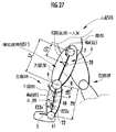
本発明の一実施形態を図1〜図26を参照して説明する。図1は本実施形態に係る脚体運動補助装具1を人Aに装着した状態を側面視で示し、図2は該脚体運動補助装具1を装着した人Aの下半身を正面視で示している。なお、図2では、説明の便宜上、人Aの各脚体の股関節、膝関節、足首関節を一点鎖線の円で表している。
An embodiment of the present invention will be described with reference to FIGS. FIG. 1 shows a state in which the leg
これらの図1および図2において、脚体運動補助装具1(以下、単に補助装具1という)は、人Aの腰部に固定された腰装着部2と、人Aの左右の各脚体の足平部にそれぞれ固定された左右一対の足平装着部3,3と、これらの腰装着部2と左右の各足平装着部3,3とをそれぞれ連結する左右一対の脚リンク部4,4を備えている。なお、「左右」というのは、人Aの前方に向かって左右という意味である。
In FIG. 1 and FIG. 2, a leg exercise assisting device 1 (hereinafter simply referred to as an assisting device 1) includes a
腰装着部2は、腰部の外周囲に巻き付けられて該腰部に固定されたベルト状の部材から構成され、その背面部には、後述のセンサ等を収容したセンサボックス5が固定されている。
The
各脚リンク部4は、センサボックス5から人Aの各脚体の股関節の側方箇所まで延設された腰リンク部材6と、この腰リンク部材6の先端から該股関節に対応する関節部位7(以下、股関節部位7という)を介して人Aの各膝関節のほぼ側方箇所まで延設された大腿リンク部材8と、この大腿リンク部材8の先端(下端)から該膝関節に対応する関節部位9(以下、膝関節部位9という)を介して人Aの各足首関節の側方箇所まで延設された下腿リンク部材10と、この下腿リンク部材10の先端(下端)から該足首関節に対応する関節部位11(以下、足首関節部位11という)を介して人Aの足平部の底面に向かって延設された足平リンク部材12とを備えている。この場合、各脚リンク部4は、人Aの各脚体の外側面側(左脚体の左側、右脚体の右側)で、概ね該脚体に沿うように延在している。
Each
各足平装着部3は、その本体が、人Aの各足平部の底面に当接された概略板状の足平基体13から構成され、この足平基体13を人Aの足平部にベルト部材14で縛りつけることにより該足平部に固定されている。そして、該足平装着部3は、その足平基体13が脚リンク部4の足平リンク部材12の下端部に固定されると共に、ベルト部材14を介して足平リンク部材12に固定され、これにより、該脚リンク部4に連結されている。なお、図2ではベルト部材14を省略している。
Each
この足平装着部3は、人Aの各脚体の着地期(各脚体の足平部に床反力を受ける時期)において、該脚体の足平部が足平装着部3の足平基体13上に載った状態で、該足平基体13が人Aの重量を受けつつ接地することとなる。従って、人Aの着地期において各足平部に作用すべき床反力は、その大部分(主に人Aの重量(重力)に釣り合う成分)が足平装着部2の足平基体13を介して人Aの足平部に作用し、脚リンク部4には作用しない。なお、足平装着部3は、例えば人Aの足平部に履かせる靴状のもので構成し、それを足平リンク部材12に固定するようにしてもよい。
This
各脚リンク部4の股関節部位7、膝関節部位9および足首関節部位11は、該脚リンク部4に対応する人Aの脚体の屈伸運動に伴う回転運動(図1の紙面に概ね垂直な軸廻り(より詳しくは後述の脚平面にほぼ垂直な軸廻り)の回転運動)が可能とされている。また、前記腰リンク部材6は、センサボックス5寄りの部分6aが硬質の剛体部材から構成されると共に、股関節部位7寄りの部分6bがゴム等の弾性材から構成されている。その弾性材部分6bは、人Aの脚体の外転・内転運動(脚体の大腿部を人Aの股関節でほぼ前後方向の軸廻りに回転させる運動)と旋回運動(脚体の大腿部を人Aの股関節でほぼ上下方向の軸心廻りに回転させる運動)とに応じて弾性変形するようになっている。これにより、各脚リンク部4の股関節部位7(ひいては各脚リンク部4の、股関節部位7から下側の部分)は、該脚リンク部4に対応する人Aの脚体の屈伸運動に応じて回転するだけでなく、人Aの脚体の外転・内転運動と旋回運動とに応じて動くことが可能となっている。また、詳細な構造説明は省略するが、下腿リンク部材10は、人Aの足平部の足首関節廻りの旋回運動(足平部を下腿部の軸心廻りに回転させる運動)に伴う足平装着部3の運動が可能なように構成されている。
The hip
なお、図1では、図示の便宜上、各脚リンク部4の大腿リンク部材8の軸心と人Aの大腿部の軸心とが同方向に向き、且つ、下腿リンク部材10の軸心と人Aの下腿部の軸心とが同方向に向くようになっているが、必ずしもそのようになっている必要はない。すなわち、各脚リンク部4の膝関節部位9の位置が、人Aの膝関節の側方箇所(真横)から前後方向あるいは上下方向に多少ずれていてもよい。
In FIG. 1, for convenience of illustration, the axis of the
各脚リンク部4の股関節部位7および膝関節部位9には、それぞれの関節部位7,9に回転力を発生する回転力発生手段としての電動モータ15,16が取り付けられている。これらの電動モータ15,16はそれぞれ、各脚リンク部4の外側面側に配置されている。この場合、電動モータ15は、前記腰リンク部材6に対して大腿リンク部材8を股関節部位7の回転軸心廻りに回転させる回転力(トルク)を発生可能であり、電動モータ16は、大腿リンク部材8に対して下腿リンク部材10を膝関節部位9の回転軸心廻りに回転させる回転力(トルク)を発生可能である。なお、回転力発生手段は、電動モータの代わりに、例えば空圧アクチュエータ等により構成してもよい。
また、図2に示すように、各脚リンク部4の大腿リンク部材8の内側面(人Aの大腿部に臨む面部)と、人Aの大腿部との間には、該大腿部の上部および下部の周囲に巻き付けられたベルト部材17,18を介して該大腿部に固定されたプレート部材19が配置されている。このプレート部材19は、図示を省略するスライド機構を介して大腿リンク部材8に取り付けられ、該大腿リンク部材8の軸心方向(股関節部位7と膝関節部位9とを結ぶ線分方向)で該大腿リンク部材8に対して移動自在とされている。従って、大腿リンク部材8は、プレート部材19およびベルト部材17,18を介して人Aの大腿部に連結されている。そして、このプレート部材19と大腿リンク部材8との間には、大腿リンク部材8がプレート部材19を介して人Aの大腿部から受ける並進力(大腿部リンク部材8の軸心方向に直交する方向の並進力)あるいはその反力を検出する力センサ20と、該プレート部材19の大腿リンク部材8に対する移動量を検出する変位センサ21とが介装されている。
Further, as shown in FIG. 2, between the inner side surface of the
また、下腿リンク部材10の下端部には力センサ22が介装され、該下腿リンク部材10は、該力センサ22を介して足首関節部位11に連結されている。この力センサ22は、各脚リンク部4が足平装着部3を介して床から受ける床反力(詳しくは人Aの脚体の運動に伴う補助装具1の運動を、補助装具1が単独で行なうとした場合に該補助装具1の各脚リンク部4に作用する床反力)と該脚リンク部4が人Aの足平部から足平装着部3を介して受ける並進力との合力が足平リンク部材12および足首関節部位11を介して伝達され、その伝達される合力あるいは該合力の反力を検出するものである。
In addition, a
補足すると、人Aの各脚体の着地期において、人Aの重量は、人Aの足平部を載せて接地する足平装着部3の足平基体13に作用するので、力センサ22には、人Aの重量は作用しない。より詳しくは、補助装具1を装着した人Aの運動が、該人Aから補助装具1を取り外して行なわれているとした場合に、該人Aの各脚体に作用する床反力(人Aの運動を人Aが単独で行なう上で動力学的に必要な床反力であり、その床反力の両脚体についての総和は、当該単独の人Aに作用する重力と該人Aがその運動によって発生する慣性力との総和に釣り合うものとなる)は、その大部分が足平基体13を介して人Aの脚体にそのまま作用するので、各脚リンク部4にはほとんど伝達されない。また、本実施形態では、各脚リンク部4の足首関節部位11には、そこに回転力を発生する電動モータなどの手段が備えられず、該足首関節部位11は回転自在である。このため、力センサ22には、前記合力が伝達されるものとなる。なお、本実施形態では、力センサ22は、基本的には、各脚リンク部4の、膝関節部位9よりも足平装着部3寄りの部分に設けられていればよく、例えば各脚リンク部4の足平リンク部材12に介装してもよい。
Supplementally, in the landing stage of each leg of the person A, the weight of the person A acts on the
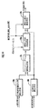
前記センサボックス5の内部には、図3のブロック図で示すように、3軸方向の加速度(並進加速度)を検出する加速度センサ23と、3軸廻りの角速度を検出するジャイロセンサ(角速度センサ)24と、マイクロコンピュータを用いて構成された演算処理装置25と、後述する光ファイバ26,27に導入する光を発光したり、戻り光を受光する発光/受光器28と、演算処理装置25の指令を受けて前記各電動モータ15,16の発生トルクを制御するモータ駆動回路29と、演算処理装置25等の各電装品の電源としてのバッテリ(蓄電器)30とが収容されている。発光/受光器28、加速度センサ23、ジャイロセンサ24はその検出出力を演算処理装置25に入力するようにしている。なお、センサボックス5は、人Aの腰部に前記腰装着部2を介して固定されているので、加速度センサ23およびジャイロセンサ24は、人Aの腰部と一体的に動くようになっている。
Inside the
補助装具1は、前記変位センサ21、力センサ20,22、加速度センサ23およびジャイロセンサ24の他、次のようなセンシング構成を備えている。
In addition to the
すなわち、図2に示す如く、各脚リンク部4の股関節部位7、膝関節部位9および足首関節部位11に、それぞれの関節部位の変位量(回転角)を検出する関節変位センサ31,32,33がそれぞれ取り付けられている。これらの関節変位センサ31〜33の検出出力は図示しない信号線を介してセンサボックス5の前記演算処理装置25に入力される。なお、前記変位センサ21、力センサ20,22の検出出力も図示しない信号線を介してセンサボックス5の演算処理装置25に入力される。
That is, as shown in FIG. 2,
関節変位センサ31〜33のうち、股関節部位7の関節変位センサ31が検出する変位量は、股関節部位7の3軸廻りの回転角(3つの軸廻りの回転角の組からなる3次元量)であり、膝関節部位9の関節変位センサ32が検出する変位量は、膝関節部位9の1軸廻りの回転角、足首関節部位11の関節変位センサ33が検出する変位量は、足首関節部位11の1軸廻りの回転角である。この場合、関節変位センサ31が検出する回転角のうちの1つの回転角の回転軸と、関節変位センサ32,33が各々検出する回転角の回転軸とは、それぞれ図2に示す如く、それらのセンサ31〜33に対応する人Aの脚体の股関節、膝関節、足首関節のそれぞれのほぼ中心を通る平面としての脚平面PL(図2の紙面に垂直な平面)にほぼ垂直な軸a31,a32,a33である。これらの軸a31,a32,a33は、それぞれ股関節部位7、膝関節部位9、足首関節部位11の回転軸である。関節変位センサ31〜33は、それぞれ股関節部位7、膝関節部位9、足首関節部位11の上記の回転軸a31,a32,a33廻りの回転角をポテンショメータやロータリエンコーダを用いて検出する。
Among the
ここで、脚平面PLについて補足すると、該脚平面PLは、それに対応する人Aの脚体を膝関節で屈曲させて該脚体の屈伸を行ったときに、該脚体の股関節、膝関節、足首関節の中心点が存在するような平面である。換言すれば、各脚体の屈伸は、その股関節、膝関節、足首関節の中心点をほぼ脚平面PL上に位置させた状態で行われる。そして、例えば図2の左側脚体のように、その股関節の、前後方向の軸廻りの回転運動によって左側脚体を外転させた状態では、該左側脚体に対応する脚平面PLは鉛直方向に対して傾く。 Here, supplementing the leg plane PL, when the leg of the person A corresponding to the leg plane PL is bent at the knee joint and the leg is bent and stretched, the leg plane PL The plane is such that the center point of the ankle joint exists. In other words, each leg is bent and stretched in a state where the center points of the hip joint, the knee joint, and the ankle joint are positioned substantially on the leg plane PL. And, for example, in the state where the left leg is abducted by the rotational movement of the hip joint around the longitudinal axis as in the left leg of FIG. 2, the leg plane PL corresponding to the left leg is vertical. Lean against.
股関節部位7の関節変位センサ31が検出する他の2軸廻りの回転角は、対応する脚体の脚平面PLに平行で、且つ互いに平行でない2つの軸廻りの回転角(より詳しくは、脚体の外転・内転あるいは旋回に伴う股関節部位7の姿勢の回転角)である。そして、その回転角は、例えば前記腰リンク部材6の弾性材部分6bの変形量を検出するひずみセンサや、後述するような光ファイバを利用したセンサの出力を用いて検出される。
The rotation angles around the other two axes detected by the
また、図1に示すように、センサボックス5から導出された2本の光ファイバ26,27は人Aの胴体の背面(背中)沿いに上方に向かって延設され、その先端部がそれぞれ人Aの腹部の背面、胸部の背面に図示しないバンド等の部材を介して固定されている。光ファイバ26,27は、それぞれ腰部に対する腹部、胸部の傾き角を検出する検出手段の構成要素である。これらの光ファイバ26,27を用いた腹部、胸部の傾き角の計測は次のような手法により行われる。光ファイバ26を用いた腹部の傾き角の計測手法を代表的に説明すると、該光ファイバ26には、センサボックス5内の前記発光/受光器28から所定の強度の光が導入されると共に、その導入された光が該光ファイバ26の先端で反射されてセンサボックス5側に戻ってくるようになっている。そして、その光の戻り量(戻った光の強度)が前記発光/受光器28により検出されるようになっている。また、光ファイバ26には、微小な光漏れを許容する複数の刻み部(図示しない)が長手方向に間隔を存して設けられており、光ファイバ26に導入された光のうち、腰部に対する腹部の傾き角に応じた量の光がそれらの刻み部を介して光ファイバ26から漏出する。このため、センサボックス5側への光の戻り量は、腹部の傾き角に応じたものとなり、その戻り量を検出することで、腰部に対する腹部の傾き角が計測される。すなわち、光ファイバ26の光の戻り量に応じた発光/受光器28の検出出力が、腰部に対する腹部の傾き角に応じたものとなり、それが該傾き角を示す信号として演算処理装置25に入力される。光ファイバ27を用いた胸部の傾き角の計測手法も同様である。なお、本実施形態で、光ファイバ26,27を用いて上記のように検出する腹部および胸部の傾き角は、人Aの矢状面(側面視)での傾き角である。
Further, as shown in FIG. 1, the two
補足すると、前記関節変位センサ31〜33がそれぞれ検出する股関節部位7、膝関節部位9、足首関節部位11の回転角は、補助装具1の各脚リンク部4をほぼ鉛直方向に延ばすと共に、足平装着部3の足平基体13をほぼ水平姿勢にした状態(以下、この状態を補助装具1の基準姿勢状態という)を基準(ゼロ点)とする回転角である。また、光ファイバ26,27を用いてそれぞれ検出する腹部、胸部の傾き角は、補助装具1を装着した人Aが水平な床面に直立姿勢(人Aの各脚体および胴体をほぼ鉛直方向に向けた姿勢)で起立した状態(以下、この状態を人Aの基準姿勢状態という)を基準とする傾き角である。
Supplementally, the rotation angles of the hip
さらに、補助装具1は、図1に示す如く、各足平装着部3の足平基体13の底面に、2つの接地センサ34,35を備えている。これらの接地センサ34,35のうち、接地センサ34は人Aの足首関節の直下の箇所(踵)に設けられ、接地センサ35は人Aの足平部の中足趾節関節(足平部の親指の付け根の関節)の直下の箇所(つま先)に設けられている。これらの接地センサ34,35は、それを設けた箇所が接地しているか否かを示すON/OFF信号を出力するセンサである。なお、接地センサ34,35の検出出力は信号線(図示省略)を介してセンサボックス5の演算処理装置25に入力される。
Further, as shown in FIG. 1, the
以上が本実施形態での補助装具1の構成である。
The above is the configuration of the
次に、本実施形態で用いる人Aの剛体リンクモデル(幾何学モデル)、補助装具1の剛体リンクモデル(幾何学モデル)、および座標系について説明しておく。図4は、人Aの剛体リンクモデルS1の構造と座標系とを示している。なお、後述する如く、本実施形態では、補助装具1の剛体リンクモデルの基本構造は人Aの剛体リンクモデルS1と同一とされており、図4は補助装具1の剛体リンクモデルの構造を示すものでもある。そのため、図4では、補助装具1の剛体リンクモデルを示す参照符号S1’を括弧付きで示している。
Next, the rigid link model (geometric model) of the person A, the rigid link model (geometric model) of the
図4に示す如く、本実施形態では、人Aの剛体リンクモデルS1は、9個の剛体要素と8個の関節要素とで構成される連結体として表現される。図4では、各剛体要素は線分で表され、各関節要素は円(参照符号J4を付したものを除く)で表されている。以下、詳説すると、この剛体リンクモデルS1は、大別すると、人Aの各脚体にそれぞれ対応する一対の脚体部S2,S2と、人Aの上体(腰部から上側の部分)に対応する上体部S3とから構成される。上体部S3は、人Aの腰部に対応する剛体要素S4と腹部に対応する剛体要素S5とを関節要素JU1で連結し、さらに、剛体要素S5と胸部に対応する剛体要素S6とを関節要素JU2で連結してなる連結体として構成されている。以下、剛体要素S4〜S6をそれぞれ腰部要素S4、腹部要素S5、胸部要素S6と称し、関節要素JU1、JU2をそれぞれ上体下部関節JU1、上体上部関節JU2と称することがある。 As shown in FIG. 4, in the present embodiment, the rigid link model S1 of the person A is expressed as a connected body including nine rigid elements and eight joint elements. In FIG. 4, each rigid body element is represented by a line segment, and each joint element is represented by a circle (excluding the reference numeral J4). In detail, the rigid link model S1 is roughly divided into a pair of leg portions S2 and S2 corresponding to each leg of the person A, and an upper body (portion above the waist) of the person A. And upper body part S3. The upper body part S3 connects the rigid body element S4 corresponding to the waist of the person A and the rigid body element S5 corresponding to the abdomen by the joint element JU1, and further connects the rigid body element S5 and the rigid body element S6 corresponding to the chest part to the joint element. It is configured as a connected body connected by JU2. Hereinafter, the rigid body elements S4 to S6 may be referred to as a waist element S4, an abdomen element S5, and a chest element S6, respectively, and the joint elements JU1 and JU2 may be referred to as an upper body lower joint JU1 and an upper body upper joint JU2, respectively.
この場合、腰部要素S4の上端に前記上体下部関節JU1が設けられると共に、腰部要素S4の下部の左右両端に人Aの一対の股関節に対応する一対の関節要素J1,J1(以下、単に股関節J1と称することがある)が設けられている。また、上体下部関節JU1は、人Aの腰部と腹部との境界付近で人Aの背骨上に想定した関節に対応するものであり、上体上部関節JU2は、腹部と胸部との境界付近で人Aの背骨上に想定した関節に対応するものである。剛体リンクモデルS1では、人Aの胴体の曲げ動作に対応する上体部S3の曲げ動作は、上体下部関節JU1および上体上部関節JU2の2つの関節要素で行われる。 In this case, the lower body joint JU1 is provided at the upper end of the waist element S4, and a pair of joint elements J1, J1 (hereinafter simply referred to as a hip joint) corresponding to the pair of hip joints of the person A at the left and right ends of the lower part of the waist element S4. J1) may be provided. The lower body joint JU1 corresponds to the joint assumed on the spine of the person A near the boundary between the waist and the abdomen of the person A, and the upper body joint JU2 is near the boundary between the abdomen and the chest. This corresponds to the joint assumed on the spine of the person A. In the rigid link model S1, the bending operation of the upper body part S3 corresponding to the bending operation of the torso of the person A is performed by two joint elements, the upper body lower joint JU1 and the upper body upper joint JU2.
剛体リンクモデルS1の各脚体部S2は、人Aの大腿部に対応する剛体要素である大腿部要素S7を前記股関節J1を介して腰部要素S4に連結し、下腿部に対応する剛体要素である下腿部要素S8を膝関節に対応する関節要素J2を介して大腿部要素S7に連結し、足平部に対応する剛体要素である足平部要素S9を足首関節に対応する関節要素J3を介して下腿部要素S8に連結してなる連結体として構成されている。以下、剛体要素S7〜S9をそれぞれ大腿部要素SS7、下腿部要素S8、足平部要素S9と称し、関節要素J2,J3をそれぞれ単に膝関節J2、足首関節J3と称することがある。 Each leg part S2 of the rigid link model S1 connects the thigh element S7, which is a rigid element corresponding to the thigh of the person A, to the waist element S4 via the hip joint J1, and corresponds to the lower leg part. the crus element S8 is rigid element via a joint element J2 corresponding to the knee joint concatenates the thigh element S7, the foot element S9 is rigid element corresponding to the foot in the ankle joint It is configured as a corresponding coupling member formed by concatenating the crus element S8 via the joint element J3. Hereinafter, the rigid elements S7 to S9 may be referred to as a thigh element SS7, a crus element S8, and a foot element S9, respectively, and the joint elements J2 and J3 may be simply referred to as a knee joint J2 and an ankle joint J3, respectively.
なお、図4において、足平部要素S9の先端の参照符号J4を付した部分は、人の足平部の親指の付け根の関節である中足趾節関節(以下、MP関節という)に対応する部分である。剛体リンクモデルS1では、部分J4は、関節としての機能を持つものではないが、以下、便宜上、その部分J4をMP関節J4と称する。 In FIG. 4, the portion denoted by reference numeral J <b> 4 at the tip of the foot portion element S <b> 9 corresponds to a metatarsal joint joint (hereinafter referred to as an MP joint) that is a joint at the base of the thumb of a human foot portion. It is a part to do. In the rigid link model S1, the portion J4 does not have a function as a joint. However, the portion J4 is hereinafter referred to as an MP joint J4 for convenience.
以上の如く構成された人Aの剛体リンクモデルS1の各剛体要素及び各関節要素は、各関節要素の回転運動によって、その相互の位置関係および姿勢関係(向きの関係)が各剛体要素および各関節要素に対応する人の各部の相互の位置関係および姿勢関係と同一になるように運動可能とされている。この場合、上体下部関節JU1及び上体上部関節JU2は、それぞれ3軸廻りの回転が可能とされており、その中の1軸を計測軸として、その計測軸廻りの回転(図4に各関節要素JU1,JU2に対応して記載した矢印(回転方向を表す矢印)を参照)を計測するようにしている。その計測軸は、本実施形態では、前記一対の股関節J1,J1の中心を結ぶ線分と平行な軸(後述する身体座標系BCのY軸に平行な軸)である。また、各脚体部S2の股関節J1は、左脚体部S2の股関節J1に関して代表的に図4中に記載した矢印(回転方向を表す矢印)で示す如く3軸廻りの回転が可能とされている。さらに、各脚体部S2の膝関節J2および足首関節J3はそれぞれ、左側の脚体部S2の各関節要素J2,J3に関して代表的に図4中に記載した矢印(回転方向を表す矢印)で示す如く1軸廻りの回転が可能とされている。膝関節J2および足首関節J3のそれぞれの回転軸は、股関節J1、膝関節J2および足首関節J3のそれぞれの中心を通る脚平面PL(図4では左脚体部S2については図示を省略している)に垂直な軸である。右脚体部S2の股関節J1、膝関節J2、および足首関節J3の回転動作についても左脚体部S2と同様である。この場合、右脚体部S2の膝関節J2および足首関節J3のそれぞれの回転軸(1軸)は、該右脚体部S2に対応して図示した脚平面PLに垂直な軸である。なお、各股関節J1は、いずれの脚体部S2についても3軸廻りの回転が可能であるから、それぞれの脚体部S2に対応する脚平面PLに垂直な軸廻りの回転も可能である。 Each rigid element and each joint element of the rigid link model S1 of the person A configured as described above have a mutual positional relation and posture relation (orientation relation) depending on the rotational motion of each joint element. It is possible to exercise so as to be the same as the mutual positional relationship and posture relationship of each part of the person corresponding to the joint element. In this case, each of the lower body joint JU1 and the upper body joint JU2 can be rotated around three axes, and one of the rotations can be used as a measurement axis. The arrows described in correspondence with the joint elements JU1 and JU2 (see the arrow indicating the rotation direction) are measured. In this embodiment, the measurement axis is an axis parallel to a line segment connecting the centers of the pair of hip joints J1 and J1 (an axis parallel to a Y axis of a body coordinate system BC described later). Further, the hip joint J1 of each leg S2 can be rotated about three axes as indicated by the arrows (arrows indicating the rotation direction) shown in FIG. 4 with respect to the hip J1 of the left leg S2. ing. Furthermore, the knee joint J2 and the ankle joint J3 of each leg part S2 are respectively arrows shown in FIG. 4 (arrows indicating the rotation direction) with respect to the joint elements J2 and J3 of the left leg part S2. As shown, rotation about one axis is possible. The rotation axes of the knee joint J2 and the ankle joint J3 are leg planes PL passing through the centers of the hip joint J1, the knee joint J2 and the ankle joint J3 (in FIG. 4, the left leg body portion S2 is not shown). ) Axis perpendicular to. The rotational operation of the hip joint J1, knee joint J2, and ankle joint J3 of the right leg body part S2 is the same as that of the left leg body part S2. In this case, the respective rotation axes (one axis) of the knee joint J2 and the ankle joint J3 of the right leg body portion S2 are axes perpendicular to the leg plane PL illustrated corresponding to the right leg body portion S2. Note that each hip joint J1 can rotate about three axes with respect to any leg portion S2, and therefore can also rotate about an axis perpendicular to the leg plane PL corresponding to each leg portion S2.
また、剛体リンクモデルS1では、その各剛体要素の重量および長さ(図の線分方向の長さ)並びに慣性モーメントと、各剛体要素の重心の位置(各剛体要素に固定された後述の要素座標系での位置)とがあらかじめ定められて、演算処理装置25の図示しないメモリに記憶保持されている。図4の黒点G6,G5,G4,G7,G8,G9はそれぞれ胸部要素S6、腹部要素S5、腰部要素S4、大腿部要素S7、下腿部要素S8、足平部要素S9の重心を例示的に示している。補足すると、腰部要素S4は、3つの関節要素JU1,J1,J1に連結されているので、その長さについては、両股関節J1,J1を結ぶ線分の長さと、その線分の中点と上体下部関節JU1とを結ぶ線分の長さとがある。なお、各剛体要素の長さに代えて、その剛体要素に固定された要素座標系での該剛体要素の両端点の位置を演算処理装置25に記憶保持させておいてもよい。
Further, in the rigid body link model S1, the weight and length of each rigid element (length in the direction of the line segment), the moment of inertia, and the position of the center of gravity of each rigid element (elements described later fixed to each rigid element) Position in the coordinate system) is determined in advance and stored in a memory (not shown) of the
剛体リンクモデルS1の各剛体要素の重量、長さ、慣性モーメント、重心の位置は、基本的にはそれぞれの剛体要素に対応する人Aの部位(剛体相当部)の重量、長さ、慣性モーメント、重心の位置とほぼ同一になるように設定されている。例えば、大腿部要素S10の重量、長さ、慣性モーメント、重心の位置は、それぞれ人Aの大腿部の実際の重量、長さ、慣性モーメント、重心の位置とほぼ同一である。なお、剛体リンクモデルS1の各剛体要素の重量、長さ、慣性モーメントおよび重心の位置は、人Aに補助装具1を装備していない状態での(人A単独での)重量、長さ、慣性モーメントおよび重心の位置である。また、胸部要素S6の重量、慣性モーメントおよび重心の位置は、人Aの胸部と両腕体と頭部とを合わせたものの重量、慣性モーメントおよび重心の位置である。補足すると、人Aの移動時の両腕体の運動(腕を前後に振る動作)に伴う胸部要素S6の重心の位置変化は比較的小さく、該胸部要素S6のほぼ一定の位置に維持される。
The weight of each rigid body element of the rigid body link model S1, length, Moment of inertia, The position of the center of gravity is Basically, the weight of the part (rigid body equivalent part) of person A corresponding to each rigid body element, length, Moment of inertia, It is set to be almost the same as the position of the center of gravity. For example, The weight of the thigh element S10, length, Moment of inertia, The position of the center of gravity is The actual weight of each person's A thigh, length, Moment of inertia, It is almost the same as the position of the center of gravity. In addition, The weight of each rigid body element of the rigid body link model S1, length, The moment of inertia and the position of the center of gravity are The weight of person A (without person A), without
剛体リンクモデルS1の各剛体要素の重量、長さ、慣性モーメント、重心の位置は、基本的には、人Aの各部の寸法や重量の実測値に基づいて定めればよいが、人Aの身長や体重から、人間の平均的な統計データに基づいて推定するようにしてもよい。一般に、各剛体要素に対応する人Aの剛体相当部の重心の位置や重量、長さ、慣性モーメントは、人間の身長や体重(全体重量)と相関性があり、その相関関係に基づいて人Aの身長および体重の実測データから各剛体要素に対応する人Aの剛体相当部の重心の位置や重量、長さ、慣性モーメントを比較的精度よく推定することが可能である。 The weight, length, moment of inertia, and the position of the center of gravity of each rigid element of the rigid link model S1 may be basically determined based on the measured values of the dimensions and weights of each part of the person A. You may make it estimate based on average human statistical data from height and weight. In general, the position, weight, length, and moment of inertia of the portion corresponding to the rigid body of the person A corresponding to each rigid element are correlated with the height and weight (overall weight) of the person. It is possible to estimate the position, weight, length, and moment of inertia of the center of gravity corresponding to the rigid body corresponding to each rigid element from the measured data of the height and weight of A with relatively high accuracy.
なお、図4では、便宜上、各重心G4〜G9は、それぞれに対応する剛体要素の軸心上(図示の線分上)に位置するように記載しているが、必ずしもその軸心上に位置するとは限らず、その軸心からずれた位置に存在してもよい。 In FIG. 4, for the sake of convenience, each center of gravity G4 to G9 is described so as to be located on the axis of the corresponding rigid element (on the line segment in the drawing), but is not necessarily located on that axis. However, the present invention is not limited to this, and it may exist at a position shifted from the axis.
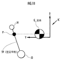
本実施形態では、剛体リンクモデルS1に対して、次のような座標系があらかじめ設定されている。すなわち、図4に示す如く身体座標系BCが腰部要素S4に固定して設定されている。この身体座標系BCは、一対の股関節J1,J1の中心を結ぶ線分の中点を原点とし、その線分の方向をY軸、原点から上体下部関節JU1の中心に向かう方向をZ軸、これらのY軸およびZ軸に直交する方向をX軸とする3次元座標系(XYZ座標系)として設定されている。人Aの前記基準姿勢状態では、身体座標系BCのX軸、Y軸、Z軸はそれぞれ人Aの前後方向、左右方向、上下方向(鉛直方向)に向き、XY平面は水平面である。 In the present embodiment, the following coordinate system is set in advance for the rigid link model S1. That is, as shown in FIG. 4, the body coordinate system BC is fixed to the waist element S4. In this body coordinate system BC, the midpoint of the line segment connecting the centers of the pair of hip joints J1 and J1 is the origin, the direction of the line segment is the Y axis, and the direction from the origin toward the center of the lower body joint JU1 is the Z axis. These are set as a three-dimensional coordinate system (XYZ coordinate system) in which the direction orthogonal to the Y axis and the Z axis is the X axis. In the reference posture state of the person A, the X axis, the Y axis, and the Z axis of the body coordinate system BC are respectively directed in the front-rear direction, the left-right direction, and the up-down direction (vertical direction) of the person A, and the XY plane is a horizontal plane.
また、各脚体部S2の一つの関節要素、例えば股関節J1に脚座標系LCが固定・設定されている。なお、図4では便宜上、右脚体部S2に対応する脚座標系LCのみを代表的に記載している。この脚座標系LCは、その一つの座標軸が該脚座標系LCに対応する脚体部S2に係る脚平面PLに垂直になるような3次元座標系である。この実施形態では、具体的には、脚座標系LCは、股関節J1の中心点を原点とし、脚平面PLに垂直な方向をY軸、身体座標系BCのZ軸を脚平面PLに投影した軸と平行な方向をZ軸、これらのY軸およびZ軸に直交する方向をX軸とする座標系とされている。従って、脚座標系LCは、換言すれば、そのXZ平面が脚平面PLと一致するような座標系である。 Further, a leg coordinate system LC is fixed and set to one joint element of each leg part S2, for example, the hip joint J1. In FIG. 4, for the sake of convenience, only the leg coordinate system LC corresponding to the right leg body portion S2 is representatively described. The leg coordinate system LC is a three-dimensional coordinate system in which one coordinate axis is perpendicular to the leg plane PL related to the leg portion S2 corresponding to the leg coordinate system LC. In this embodiment, specifically, the leg coordinate system LC projects the center point of the hip joint J1 as the origin, the direction perpendicular to the leg plane PL to the Y axis, and the Z axis of the body coordinate system BC to the leg plane PL. The coordinate system has a Z-axis as a direction parallel to the axis, and an X-axis as a direction perpendicular to the Y-axis and the Z-axis. Therefore, in other words, the leg coordinate system LC is a coordinate system whose XZ plane coincides with the leg plane PL.
さらに、各剛体要素には、例えば参照符号C4〜C9で示すように要素座標系が固定的に設定されている。本実施形態では、腰部要素S4の要素座標系C4は身体座標系BCと同一とされている。また、胸部要素S6、腹部要素S5、各大腿部要素S7、各下腿部要素S8、および各足平部要素S9のそれぞれの要素座標系C6,C5,C7,C8,C9はそれぞれ、上体上部関節JU2、上体下部関節JU1、膝関節J11、足首関節J13、MP関節J4の中心点を原点とする3次元座標系(XYZ座標系)とされている。 Further, for each rigid element, an element coordinate system is fixedly set as indicated by reference numerals C4 to C9, for example. In the present embodiment, the element coordinate system C4 of the waist element S4 is the same as the body coordinate system BC. The element coordinate systems C6, C5, C7, C8, and C9 of the chest element S6, the abdominal element S5, the thigh elements S7, the crus elements S8, and the foot elements S9 are The three-dimensional coordinate system (XYZ coordinate system) has the origin at the center point of the upper body joint JU2, the upper body lower joint JU1, the knee joint J11, the ankle joint J13, and the MP joint J4.
なお、要素座標系C4〜C9は、それぞれに対応する剛体要素に対して固定されている限り、必ずしも上記のように設定する必要はなく、その原点や各軸の向きの設定は任意でよい。また、脚座標系LCの原点を股関節J1の中心からずらしたり、身体座標系BCを腰部要素S4と異なる部位に対して固定・設定するようにしてもよい。座標系の設定の仕方は基本的には任意でよく、種々様々な設定形態を採ることが可能である。従って、本実施形態での座標系の設定の仕方は一例に過ぎない。 The element coordinate systems C4 to C9 do not necessarily need to be set as described above as long as they are fixed with respect to the corresponding rigid elements, and the origin and the orientation of each axis may be set arbitrarily. Further, the origin of the leg coordinate system LC may be shifted from the center of the hip joint J1, or the body coordinate system BC may be fixed / set to a part different from the waist element S4. The method of setting the coordinate system may basically be arbitrary, and various setting modes can be adopted. Therefore, the method of setting the coordinate system in this embodiment is only an example.
次に、補助装具1の剛体リンクモデルを説明する。本実施形態では、補助装具1の剛体リンクモデルの連結構造は、人Aの剛体リンクモデルS1(以下、人剛体リンクモデルS1という)と同一としており、図4に示した構造を有している。従って、補助装具1の剛体リンクモデルの説明は図4を用いて行う。以下、補助装具1の剛体リンクモデルを図4に括弧書きで示す如く、参照符号S1’で表し、装具剛体リンクモデルS1’と称する。
Next, the rigid link model of the
この場合、装具剛体リンクモデルS1’の各脚体部S2の関節要素J1〜J3は、それぞれ補助装具1の股関節部位7、膝関節部位9、足首関節部位11に対応している。また、上体部S3の関節要素JU1,JU2は、人Aの場合と同様、人Aの背骨上に想定した関節に対応している。また、本実施形態では、装具剛体リンクモデルS1’の各関節要素J1〜J3,JU1,JU2のそれぞれが可能な回転も人剛体リンクモデルS1と同一である。
In this case, the joint elements J1 to J3 of the leg portions S2 of the orthosis rigid link model S1 'correspond to the hip
装具剛体リンクモデルS1’の各剛体要素S4〜S9は、補助装具1のうち、該剛体要素に対応する人Aの部位に装着された部分、あるいは該部位と一体的に可動な部分が対応している。例えば装具剛体リンクモデルS1’の腰部要素S4は、補助装具1のうち、前記腰装着部2、センサボックス5および腰リンク部材6から構成される部分が対応している。また、例えば装具剛体リンクモデルS1’の各大腿部要素S5は、補助装具1のうち、各脚リンク部4の股関節部位7と膝関節部位9との間の部分(前記大腿部リンク部材8、スライド機構(図示しない)、プレート部材19、ベルト部材17,18、変位センサ21および力センサ20から構成される部分)に対応している。他の剛体要素についても同様である。但し、補助装具1の、各脚リンク部4の各関節部位7,9,11およびその関節部位に取り付けられたもの(電動モータ15,16および関節変位センサ31〜33)については、各関節部位7,9,11およびその関節部位に取り付けられたものの半体が、該関節部位に対応する関節要素で連結された剛体要素のそれぞれに含まれるものとする。例えば、装具剛体リンクモデルS1’の股関節部位7とこれに取り付けられた関節変位センサ31および電動モータ15は、そのそれぞれの半体が、腰部要素S4、大腿部要素S7に含まれるものとする。
Each of the rigid body elements S4 to S9 of the orthosis rigid link model S1 ′ corresponds to a part of the
そして、装具剛体リンクモデルS1’の各剛体要素S4〜S9の重量、長さ、慣性モーメント並びに重心の位置(各剛体要素に固定された要素座標系での位置)があらかじめ演算処理装置25のメモリに記憶保持されている。この場合、各剛体要素の要素座標系は、例えば人剛体リンクモデルS1と同様に設定されている。また、装具剛体リンクモデルS1’の各剛体要素S4〜S9の重量、慣性モーメントおよび重心の位置は、補助装具1の単体(人Aから取り外した補助装具1)での重量、慣性モーメントおよび重心の位置である。
The weight, length, moment of inertia and position of the center of gravity (position in the element coordinate system fixed to each rigid element) of the rigid elements S4 to S9 of the orthosis rigid link model S1 ′ are stored in advance in the memory of the
また、装具剛体リンクモデルS1’の座標系に関し、本実施形態では、装具剛体リンクモデルS1’の腰部要素S4の要素座標系C4は、人剛体リンクモデルS1の腰部要素S4の要素座標系C4(=身体座標系BC)と同一とされている。また、装具剛体リンクモデルS1’の左脚体部S2に係る脚座標系LCは、前記人剛体リンクモデルS1の左脚体部S2に係る脚座標系LCと同様に、該装具剛体リンクモデルS1’の左股関節J1の中心を原点とし、前記左脚平面PLに平行な面をXZ平面とする(左脚平面PLに垂直な方向をY軸とする)座標系とされている。装具剛体リンクモデルS1’の右脚体部S2に係る脚座標系LCについても同様である。また、補助装具1の足平装着部3は、人Aの足平部に固定されることから、本実施形態では、装具剛体リンクモデルS1’の各足平部要素S9の要素座標系C9は、人剛体リンクモデルS1の各足平部要素S9の要素座標系C9と同一とされている。なお、補助装具1を人Aに装備した状態における人Aの股関節の中心と、補助装具1の股関節部位7の中心との位置関係はほぼ固定的に定まるので、装具剛体リンクモデルS1’における脚座標系LCを人剛体リンクモデルS1における脚座標系LCと同一にしてもよい。
Further, regarding the coordinate system of the orthosis rigid link model S1 ′, in this embodiment, the element coordinate system C4 of the hip element S4 of the orthosis rigid link model S1 ′ is the element coordinate system C4 of the hip element S4 of the human rigid link model S1 ( = The same as the body coordinate system BC). Further, the leg coordinate system LC related to the left leg part S2 of the orthosis rigid link model S1 ′ is similar to the leg coordinate system LC related to the left leg part S2 of the human rigid link model S1. The center of the left hip joint J1 is the origin, and the plane parallel to the left leg plane PL is the XZ plane (the direction perpendicular to the left leg plane PL is the Y axis). The same applies to the leg coordinate system LC related to the right leg part S2 of the orthosis rigid link model S1 '. Further, since the
補足すると、本実施形態では、装具剛体リンクモデルS1’では、各足平部要素S9は、より詳しくは、図5に示す構造を有するものとされている。すなわち、足首関節J3に概略平板状の足平基体S9cが連結され、この足平基体S9cの前部(つま先寄り部分)および後部(踵部寄りの部分)の下面にそれぞれ床に接地する支持部S9a,S9bが備えられている。そして、装具剛体リンクモデルS1’の足平部要素S9に関しては、その長さの代わりに、足平部要素S9の要素座標系C9における支持部S9a,S9bの位置(支持部S9a,S9bの下端の位置)が演算処理装置25のメモリに記憶保持されている。
Supplementally, in the present embodiment, in the orthosis rigid link model S1 ′, each foot element S9 has a structure shown in FIG. 5 in more detail. That is, a substantially flat foot base S9c is connected to the ankle joint J3, and support portions that are respectively grounded on the lower surfaces of the front portion (toe-toe portion) and rear portion (toward the heel portion) of the foot base body S9c. S9a and S9b are provided. Then, with respect to the foot element S9 in orthosis rigid link model S1 ', instead of its length, the support portion S9a in element coordinates C9 of foot element S9, the position of the S9b (supporting portion S9a, the lower end of S9b Is stored in the memory of the
なお、本実施形態では、身体座標系BC上での装具剛体リンクモデルS1’の上体下部関節JU1、上体上部関節JU2、腹部要素S5、および胸部要素S6の位置・姿勢は、それぞれ人剛体リンクモデルS1の上体下部関節JU1、上体上部関節JU2、腹部要素S5、および胸部要素S6の位置・姿勢と同一とされている。但し、補助装具1の、人Aの腹部および胸部に対応する部分の重量や慣性モーメントは他の部分の重量や慣性モーメントに比して十分に小さく、実質的に0として差し支えない。従って、装具剛体リンクモデルS1’の腰部要素S4よりも上側の要素、すなわち、上体下部関節JU1、腹部要素S5、上体上部関節JU2、胸部要素S6は省略してもよい。
In the present embodiment, the position / posture of the upper body lower joint JU1, the upper body upper joint JU2, the abdominal element S5, and the chest element S6 on the body rigid link model S1 ′ on the body coordinate system BC are human rigid bodies, respectively. The position and posture of the lower body joint JU1, the upper body joint JU2, the abdomen element S5, and the chest element S6 of the link model S1 are the same. However, the weight and moment of inertia of the
前記人剛体リンクモデルS1および装具剛体リンクモデルS1’は、その瞬時瞬時の姿勢(各要素の相互の位置および姿勢関係)が、それぞれ人A、補助装具1の瞬時瞬時の姿勢と同じような姿勢になるものとされている。従って、以降の説明では、しばしば、人剛体リンクモデルS1の各要素と、該要素に対応する人Aの部位とを同一視し、人剛体リンクモデルS1の各要素を、それに対応する人Aの部位と同じものとして使用することがある。例えば人剛体リンクモデルS1の各脚体部S2を人Aの各脚体を同じものとして使用することがある。装具剛体リンクモデルS1’の各要素と、それに対応する補助装具1の部位との関係についても同様とする。例えば装具剛体リンクモデルS1’の各脚体部S2、大腿部要素S7、下腿部要素S8、足平部要素S9をそれぞれ、補助装具1の各脚リンク部4(但しこの場合足平装着部3を含む)、大腿リンク部材8、下腿リンク部材10、足平装着部3と同じものとして使用することがある。
The human rigid link model S1 and the orthosis rigid link model S1 ′ have instantaneous instantaneous postures (reciprocal positions and postures of the respective elements) similar to the instantaneous instantaneous postures of the person A and the
次に前記演算処理装置25の処理機能の概要を説明する。図6は演算処理装置25の処理機能の全体を概略的に示すブロック図、図7および図8は、演算処理装置25の要部の処理機能を示すブロック図である。
Next, an outline of processing functions of the
演算処理装置25の処理機能は、それを大別すると、人Aの脚体の運動が行なわれている時(人Aの歩行時など)に、その脚体の運動が人Aから補助装具1を取り外して行なわれているとした場合(人Aが補助装具1を装着せずに自力で各脚体の所望の運動を行ったと仮定した場合)に人Aの各脚体の各関節(足首関節、膝関節、股関節)に発生すべき関節モーメントを逐次推定する人側関節モーメント推定手段41と、人Aの脚体の運動に伴う補助装具1の運動を、該補助装具1が単独で(人Aから取り外された補助装具1が自力で)行なっているとした場合に補助装具1の各関節部位7,9,11に発生すべき関節モーメントを逐次推定する装具側関節モーメント推定手段42と、補助装具1の電動モータ15,16の作動によって各脚体の股関節および膝関節に発生させるべき目標モーメントである目標関節補助モーメントを前記人側関節モーメント推定手段41で推定された関節モーメントに応じて決定する目標関節補助モーメント決定手段43と、補助装具1の電動モータ15,16の作動によって人Aの股関節および膝関節にそれぞれ実際に発生している関節モーメントである実関節補助モーメントの推定値を前記力センサ20,22、変位センサ21の出力などを基に逐次求める実関節補助モーメント推定手段44と、前記装具側関節モーメント推定手段42でそれぞれ推定された関節モーメントと前記目標関節補助モーメント決定手段43で決定された股関節および膝関節の目標関節補助モーメントと前記実関節補助モーメント推定手段44で推定された膝関節および股関節の実関節補助モーメントの推定値とを用い、股関節および膝関節のそれぞれの実関節補助モーメントの推定値を目標関節補助モーメントに一致させるように各電動モータ15,16をモータ駆動回路29を介してフィードバック制御するモータ制御手段45とから構成される。
The processing function of the
この場合、人側関節モーメント推定手段41は、さらに詳しくは、図7に示すように、各股関節部位4の関節変位センサ31および発光/受光器28の検出出力を基に後述する座標変換のための変換テンソルを作成する変換テンソル作成手段51と、各関節変位センサ31,32,33の検出出力を基に、人剛体リンクモデルS1の各脚体部S2の脚平面PL上での各関節要素の位置、各剛体要素の姿勢(傾斜角)、および各剛体要素の重心の位置を求める2次元脚姿勢・要素重心位置算出手段52と、変換テンソル作成手段51が作成した変換テンソルと2次元脚姿勢・要素重心位置算出手段52が求めた位置・姿勢とを用いて人剛体リンクモデルS1の各関節要素および各剛体要素の重心の身体座標系BCでの3次元的な位置ベクトルの値(座標成分値)を求める3次元関節・要素重心位置算出手段53と、前記加速度センサ23及びジャイロセンサ24の検出出力を基に身体座標系BCの原点の加速度ベクトル(並進加速度)および角速度ベクトルの値(身体座標系BCでの座標成分値)を求める身体座標系加速度・角速度算出手段54と、前記加速度センサ23及びジャイロセンサ24の検出出力を基に身体座標系BCの鉛直方向に対する傾斜角を算出する身体座標系傾斜角算出手段55とを備えている。なお、3次元関節・要素重心位置算出手段53が求める位置ベクトルには、人剛体リンクモデルS1の各足平部要素S9のMP関節J4の身体座標系BCでの位置ベクトルも含まれる。
In this case, the human-side joint moment estimating means 41 is more specifically for coordinate conversion to be described later based on the detection output of the
さらに人側関節モーメント推定手段41は、3次元関節・要素重心位置算出手段53が求めた人剛体リンクモデルS1の各剛体要素の重心の位置ベクトルの値を用いて身体座標系BCでの人剛体リンクモデルS1の全体重心(人Aの全体重心)の位置ベクトルの値を求める全体重心位置算出手段56を備えている。 Further, the human side joint moment estimating means 41 uses the position vector value of the center of gravity of each rigid body element of the human rigid body link model S1 obtained by the three-dimensional joint / element center of gravity position calculating means 53 to use the human rigid body in the body coordinate system BC. There is provided an overall center of gravity position calculating means 56 for obtaining a position vector value of the overall center of gravity (total center of gravity of the person A) of the link model S1.
また、人側関節モーメント推定手段41は、3次元関節・要素重心位置算出手段53が求めた各足首関節J3および各MP関節J4の位置ベクトルの値と身体座標系傾斜角算出手段55が求めた身体座標系BCの傾斜角と全体重心位置算出手段56が求めた全体重心の位置ベクトルの値と接地センサ34,35の検出出力とを用いて各脚体(各脚体部S2)に作用する床反力(並進床反力のベクトル)の作用点(以下、単に床反力作用点という)の位置ベクトルの身体座標系BCでの値を求める床反力作用点推定手段57と、3次元関節・要素重心位置算出手段53が求めた各関節要素および各剛体要素の重心の位置ベクトルの値と全体重心位置算出手段56が求めた全体重心の位置ベクトルの値と身体座標系加速度・角速度算出手段54が求めた身体座標系BCの原点の加速度ベクトルおよび角速度ベクトルの値と前記接地センサ34,35の検出出力と前記床反力作用点推定手段57が求めた床反力作用点の位置ベクトルの値とを用いて人Aの各脚体に作用する床反力(並進床反力のベクトル)の身体座標系BCでの値(座標成分値)を推定する床反力推定手段58とを備える。なお、床反力推定手段58が推定する床反力は、より詳しくは、人Aの運動が、人Aから補助装具1を取り外して行なわれているとした場合に該人Aの各脚体に作用する床反力である。
Further, the human side joint moment estimating means 41 is obtained by the body coordinate system inclination
そして、人側関節モーメント推定手段41は、床反力推定手段58が求めた床反力の値と床反力作用点推定手段57が求めた床反力作用点の位置ベクトルの値と身体座標系加速度・角速度算出手段54が求めた加速度ベクトルおよび角速度ベクトルの値を、変換テンソル作成手段51が作成した変換テンソルを用いて各脚体に対応する脚平面PLに投影する脚平面投影手段59と、この投影により得られた値(2次元量)と2次元脚姿勢・要素重心位置算出手段52が求めた位置・姿勢とを用いて人Aの各脚体の足首関節、膝関節および股関節に発生すべき関節モーメントの推定値を算出する関節モーメント算出手段60とを備えている。 Then, the human side joint moment estimating means 41 calculates the floor reaction force value obtained by the floor reaction force estimating means 58, the position vector value of the floor reaction force action point obtained by the floor reaction force action point estimating means 57, and the body coordinates. Leg plane projection means 59 for projecting the acceleration vector and angular velocity vector values obtained by the system acceleration / angular velocity calculation means 54 onto the leg plane PL corresponding to each leg using the conversion tensor created by the conversion tensor creation means 51; Using the value (two-dimensional amount) obtained by this projection and the position / posture determined by the two-dimensional leg posture / element center of gravity position calculating means 52, the ankle joint, knee joint and hip joint of each leg of the person A are used. And a joint moment calculating means 60 for calculating an estimated value of the joint moment to be generated.
詳細は後述するが、人側関節モーメント推定手段41は、上記各手段51〜60の演算処理を所定の演算処理周期で逐次実行し、各演算処理周期において最終的に関節モーメント算出手段60により関節モーメントの推定値を逐次算出する。 Although details will be described later, the human-side joint moment estimating means 41 sequentially executes the calculation processes of the respective means 51 to 60 in a predetermined calculation processing cycle, and finally the joint moment calculating means 60 performs the joint in each calculation processing cycle. The estimated moment is calculated sequentially.
一方、装具側関節モーメント推定手段42は、図8に示すように、各関節変位センサ31,32,33の検出出力を基に、装具剛体リンクモデルS1’の各脚体部S2の脚座標系LCのXZ平面上での各関節要素の位置、各剛体要素の姿勢(傾斜角)、および各剛体要素の重心の位置を求める2次元脚姿勢・要素重心位置算出手段61と、この2次元脚姿勢・要素重心位置算出手段61が求めた位置・姿勢と前記人側関節モーメント推定手段41の変換テンソル作成手段51で求められた変換テンソル(図7および図8の※1を参照)とを用いて装具剛体リンクモデルS1’の各関節要素および各剛体要素の重心の身体座標系BCでの3次元的な位置ベクトルの値(座標成分値)を求める3次元関節・要素重心位置算出手段62と、この3次元関節・要素重心位置算出手段62が求めた装具剛体リンクモデルS1’の各剛体要素の重心の位置ベクトルの値を用いて身体座標系BCでの装具剛体リンクモデルS1’の全体重心(補助装具1の全体重心)の位置ベクトルの値を求める全体重心位置算出手段63とを備えている。なお、3次元関節・要素重心位置算出手段62が求める位置ベクトルには、装具剛体リンクモデルS1’の各足平要素S9の支持部S9a,S9bの下端(図5参照)の位置ベクトルも含まれる。
On the other hand, as shown in FIG. 8, the appliance side joint moment estimating means 42 is based on the detection output of each
さらに、装具側関節モーメント推定手段42は、3次元関節・要素重心位置算出手段62で求められた装具剛体リンクモデルS1’の各足平要素S9の支持部S9a,S9bの位置ベクトルの値と人側関節モーメント推定手段41の身体座標系傾斜角算出手段55が求めた身体座標系BCの傾斜角(図7および図8の※2を参照)と全体重心位置算出手段63が求めた全体重心の位置ベクトルの値と接地センサ34,35の検出出力とを用いて補助装具1の各脚リンク部4に作用する床反力(並進床反力)の作用点(床反力作用点)の位置ベクトルの身体座標系BCでの値を求める床反力作用点推定手段64と、3次元関節・要素重心位置算出手段62が求めた装具剛体リンクモデルS1’の各関節要素および各剛体要素の重心の位置ベクトルの値と全体重心位置算出手段63が求めた全体重心の位置ベクトルの値と人側関節モーメント推定手段41の身体座標系加速度・角速度算出手段54で求められた身体座標系BCの原点の加速度ベクトルおよび角速度ベクトルの値(図7および図8の※3を参照)と前記接地センサ34,35の検出出力と前記床反力作用点推定手段64が求めた床反力作用点の位置ベクトルの値とを用いて補助装具1の各脚リンク部4に作用する床反力(並進床反力のベクトル)の身体座標系BCでの値(座標成分値)を推定する床反力推定手段65とを備える。なお、床反力推定手段65が推定する床反力は、より詳しくは、人Aの脚体の運動に伴う補助装具1の運動を、該補助装具1が単独で(自力で)行なっているとした場合に該補助装具1の各脚リンク部4に作用する床反力である。
Further, the brace-side joint moment estimating means 42 calculates the position vector values of the support elements S9a and S9b of each foot element S9 of the brace rigid link model S1 ′ obtained by the three-dimensional joint / element center-of-gravity position calculating means 62 and the person. The inclination angle of the body coordinate system BC obtained by the body coordinate system inclination angle calculation means 55 of the side joint moment estimation means 41 (see * 2 in FIGS. 7 and 8) and the overall gravity center obtained by the overall gravity center position calculation means 63. The position of the action point (floor reaction force action point) of the floor reaction force (translational floor reaction force) acting on each
そして、装具側関節モーメント推定手段42は、床反力推定手段65が求めた床反力の値と床反力作用点推定手段64が求めた床反力作用点の位置ベクトルの値と人側関節モーメント推定手段41の身体座標系加速度・角速度算出手段54が求めた加速度ベクトルおよび角速度ベクトルの値を、人側関節モーメント推定手段41の変換テンソル作成手段51が作成した変換テンソル(図7および図8の※1を参照)を用いて各脚体に対応する脚平面PLに投影する(装具剛体リンクモデルS1’の脚座標系LCのXZ平面に投影する)脚平面投影手段66と、この投影により得られた値(2次元量)と前記2次元脚姿勢・要素重心位置算出手段61が求めた位置・姿勢とを用いて補助装具1の各関節部位7,9,11に発生すべき関節モーメントの推定値を算出する関節モーメント算出手段67とを備えている。
The appliance-side joint moment estimation means 42 then determines the floor reaction force value obtained by the floor reaction force estimation means 65 and the position vector value of the floor reaction force action point obtained by the floor reaction force action point estimation means 64 and the human side. A conversion tensor (FIG. 7 and FIG. 7) created by the conversion tensor creation means 51 of the human side joint moment estimation means 41 is obtained from the values of the acceleration vector and the angular velocity vector obtained by the body coordinate system acceleration / angular velocity calculation means 54 of the joint moment estimation means 41. 8) (refer to * 1 of 8) and projecting onto the leg plane PL corresponding to each leg (projecting onto the XZ plane of the leg coordinate system LC of the orthosis rigid body link model S1 ′), and this projection The joints to be generated at the
詳細は後述するが、装具側関節モーメント推定手段42は、人側関節モーメント推定手段41の処理と並行して、上記各手段61〜67の演算処理を所定の演算処理周期で逐次実行し、各演算処理周期において最終的に関節モーメント算出手段67により関節モーメントの推定値を逐次算出する。
Although details will be described later, the orthosis-side joint moment estimating means 42 sequentially executes the arithmetic processing of each of the
また、前記実関節補助モーメント推定手段44には、前記図6に示すように、装具側関節モーメント推定手段42の脚平面投影手段59で求められた脚平面PL上での床反力(装具剛体リンクモデルS1’の脚座標系LCのXZ平面上での床反力。図6および図8の※4を参照)や、力センサ20,22および変位センサ21の検出出力、装具側関節モーメント推定手段42の2次元脚姿勢・要素重心位置算出手段61で求められた装具剛体リンクモデルS1’の各脚体部S2の姿勢(大腿部要素S7の脚平面PL上での傾斜角など。図6および図8の※5を参照)が入力される。そして、実関節補助モーメント推定手段44は、これらの入力値を用いて実関節補助モーメント推定値を後述するように算出する。
Further, as shown in FIG. 6, the actual joint auxiliary moment estimating means 44 includes a floor reaction force (an orthosis rigid body) on the leg plane PL obtained by the leg plane projection means 59 of the orthosis side joint moment estimating means 42. Floor reaction force on the XZ plane of the leg coordinate system LC of the link model S1 ′ (see * 4 in FIGS. 6 and 8), detection outputs of the
次に演算処理装置25の各手段の詳細な演算処理と併せて本実施形態の装置の作動を説明する。なお、以下の説明において、一般的に、ベクトル量をある座標系Caから別の座標系Cbに座標変換する変換テンソル、すなわち座標系Caの成分値で表されるベクトル量を座標系Cbの成分値で表されるベクトル量に変換するテンソルを「R(Ca→Cb)」というように表記する。また、ある座標系Caで見たある点Pもしくは部位Pの位置ベクトルをU(P/Ca)というように表記する。また、ある座標系Caの座標成分値で表される、物体Qもしくは部位Qの作用力、加速度等の物理量のベクトルAをA(Q/Ca)というように表記する。この場合、位置ベクトルU(P/Ca)や、物理量ベクトルA(Q/Ca)の座標系Caでの座標成分値を表すときは、各座標軸の名称であるx、y、zをさらに付加して表記する。例えば、位置ベクトルU(P/Ca)のX座標成分は、U(P/Ca)xというように表記する。さらに位置ベクトルU(P/Ca)や、物理量ベクトルA(Q/Ca)の座標系Caでの2つの座標成分値の組(2次元ベクトル)を表すときには、その2つの座標軸の名称を付加して表記する。例えばベクトルA(Q/Ca)のX軸成分、Z軸成分の組からなる2次元ベクトル(これはベクトルA(Q/Ca)の、Y軸(座標系CaのY軸)に垂直な面上での成分ベクトルである)は、A(Q/Ca)x,zというように表記する。なお、着目している座標系が明らかである場合には、座標系Caの表記を省略することもある。
Next, the operation of the apparatus of the present embodiment will be described together with detailed arithmetic processing of each means of the
また、前記各要素座標系C4〜C9をそれぞれ対応する人Aの部位の名称を用いてC_腰部、C_腹部、C_胸部、C_大腿部、C_下腿部、C_足平部と称することがある。このことは、人剛体リンクモデルS1の各剛体要素S4〜S9、各剛体要素S4〜S9の重心G4〜G9についても同様とする。例えば人剛体リンクモデルS1の腰部要素S4およびその重心G4をそれぞれS_腰部、G_腰部と表記することがある。 Further, the element coordinate systems C4 to C9 are referred to as C_waist, C_abdomen, C_chest, C_thigh, C_crus, and C_foot using the names of the corresponding parts of the person A, respectively. is there. The same applies to the rigid elements S4 to S9 and the centroids G4 to G9 of the rigid elements S4 to S9 of the human rigid link model S1. For example, the waist element S4 and the center of gravity G4 of the human rigid link model S1 may be referred to as S_waist and G_waist, respectively.
さらに、装具剛体リンクモデルS1’の各剛体要素S4〜S9をそれぞれに対応する人Aの部位の名称を用いてS_腰部装具、S_腹部装具、S_胸部装具、S_大腿部装具、S_下腿部装具、S_足平部装具と称することがある。このことは、、装具剛体リンクモデルS1’の各剛体要素S4〜S9の重心についても同様とする。例えば装具剛体リンクモデルS1’の腰部要素S4の重心G4をG_腰部装具と表記することがある。 Further, using the names of the parts of the person A corresponding to the rigid elements S4 to S9 of the orthosis rigid link model S1 ′, the S_lumbar orthosis, the S_abdominal orthosis, the S_chest orthosis, the S_thigh orthosis, and the S_lower leg It may be called a part orthosis or S_foot part orthosis. The same applies to the center of gravity of each rigid element S4 to S9 of the orthosis rigid link model S1 '. For example, the center of gravity G4 of the waist element S4 of the orthosis rigid link model S1 'may be referred to as G_waist orthosis.
なお、人Aの脚体に係わるもの、あるいは補助装具1の脚リンク部4に係わるものについては、その左右を区別する必要があるときは、「右」、「左」をさらに付加して記述する。例えば右側の大腿部要素S7をS_右大腿部もしくはS_右大腿部装具と称することがある。
In addition, when it is necessary to distinguish the left and right of those related to the leg of the person A or those related to the
また、人剛体リンクモデルS1の股関節J1、膝関節J2、足首関節J3、およびMP関節J4をそれぞれJ_股、J_膝、J_足首、J_MPと称し、装具剛体リンクモデルS1’の股関節J1、膝関節J2および足首関節J3をそれぞれJ_股装具、J_膝装具、J_足首装具と称することがある。この場合も左右を区別する必要があるときは、上記と同様、「右」、「左」をさらに付加して表記する。 The hip joint J1, knee joint J2, ankle joint J3, and MP joint J4 of the human rigid link model S1 are referred to as J_crotch, J_knee, J_ankle, and J_MP, respectively, and the hip joint J1 and knee joint of the orthosis rigid link model S1 ′. J2 and ankle joint J3 may be referred to as J_hip orthosis, J_knee orthosis, and J_ankle orthosis, respectively. Also in this case, when it is necessary to distinguish between left and right, “right” and “left” are further added in the same manner as described above.
演算処理装置25は、所定の演算処理周期で前記各関節変位センサ31,32,33、発光/受光器28、加速度センサ23、ジャイロセンサ24、力センサ20,22、変位センサ21の検出出力を図示しないA/D変換器を介して取り込むと共に、各接地センサ34,35の検出出力(ON/OFF信号)を取り込む。そして、まず、人側関節モーメント推定手段41および装具側関節モーメント推定手段42の演算処理を並行して実行する。
The
人側関節モーメント推定手段41の演算処理を以下に詳説する。なお、以降、人側関節モーメント推定手段41の説明が終了するまでは、剛体要素、関節要素、脚座標系、要素座標系は、特に断らない限り、それぞれ人剛体リンクモデルS1の剛体要素、関節要素、脚座標系、要素座標系を意味するものとする。 The calculation processing of the human side joint moment estimation means 41 will be described in detail below. Hereinafter, until the description of the human side joint moment estimating means 41 is finished, the rigid element, the joint element, the leg coordinate system, and the element coordinate system are respectively the rigid body element and the joint of the human rigid link model S1 unless otherwise specified. It shall mean element, leg coordinate system, element coordinate system.
まず、前記変換テンソル作成手段51、2次元脚姿勢・要素重心位置算出手段52、および3次元関節・要素重心位置算出手段53の演算処理が順次実行される。 First, the calculation processes of the conversion tensor creation means 51, the two-dimensional leg posture / element centroid position calculation means 52, and the three-dimensional joint / element centroid position calculation means 53 are sequentially executed.
変換テンソル作成手段51の演算処理では、各脚座標系LCと身体座標系BCとの間のベクトル量の座標変換を行うための変換テンソルR(LC→BC)と、腹部要素S5の要素座標系C5および胸部要素S6の要素座標系C6のそれぞれと身体座標系BCの間のベクトル量の座標変換を行うための変換テンソルR(C_腹部→BC)、R(C_胸部→BC)とが作成される。 In the calculation processing of the conversion tensor creation means 51, a conversion tensor R (LC → BC) for performing coordinate conversion of vector quantities between each leg coordinate system LC and the body coordinate system BC, and an element coordinate system of the abdominal element S5. Conversion tensors R (C_abdomen → BC) and R (C_chest → BC) for performing coordinate conversion of vector quantities between the element coordinate system C6 of C5 and the chest element S6 and the body coordinate system BC are created. The
変換テンソルR(LC→BC)は、補助装具1の股関節部位7の関節変位センサ31で検出される股関節部位7の3軸廻りの回転角のうち、脚平面PLに垂直な回転軸a31の廻りの回転角を除く2つの軸廻りの回転角から決定される。本実施形態では、脚平面PLに垂直な回転軸a31を除く2つの軸廻りの股関節部位7の回転角(人Aの脚体の股関節廻りの外転・内転、および旋回に伴う股関節部位7の回転角)が決まれば、人剛体リンクモデルS1の脚座標系LCと身体座標系BCとの間の姿勢関係が一義的に定まる。従って、変換テンソルR(LC→BC)は、股関節の3軸廻りの回転角のうち、脚平面PLに垂直な回転軸a31の廻りの回転角を除く2つの軸廻りの回転角の検出値から求めることができる。なお、変換テンソルR(LC→BC)は、左右の脚体毎に各別に求められる。
The conversion tensor R (LC → BC) is a rotation angle around the rotation axis a31 perpendicular to the leg plane PL among the rotation angles around the three axes of the hip
また、変換テンソルR(C_腹部→BC)、R(C_胸部→BC)は次のように作成される。まず、発光/受光器28の検出出力を基に、人剛体リンクモデルS1の腰部要素S4に対する腹部要素S5と胸部要素S6の傾斜角(詳しくは身体座標系BCのZ軸方向に対する矢状面(XZ平面)上での傾斜角)が把握される。そして、腰部要素S4に対する腹部要素S5の傾斜角だけ、座標系C_腹部が身体座標系BCに対して矢状面上で傾いたものとして、変換テンソルR(C_腹部→BC)が決定される。同様に、腰部要素S4に対する胸部要素S6の傾斜角だけ、座標系C_胸部が身体座標系BCに対して矢状面上で傾いたものとして、変換テンソルR(C_腹部→BC)が決定される。
The conversion tensors R (C_abdomen → BC) and R (C_chest → BC) are created as follows. First, based on the detection output of the light emitting / receiving
補足すると、本実施形態では、人剛体リンクモデルS1の上体下部関節JU1および上体上部関節JU2を1軸廻り(C_腹部およびC_胸部のY軸廻り)の回転による腹部要素S5および胸部要素S6の腰部要素S4に対する傾斜角のみを計測するようにしたが、上体下部関節JU1および上体上部関節JU2をそれぞれ例えば2軸廻り(例えばC_腹部およびC_胸部のY軸とX軸との2軸廻り)の回転が可能なものとして、腹部要素S5および胸部要素S6の2軸廻りの傾斜角を計測するようにしてもよい。そして、それらの2軸廻りの傾斜角から変換テンソルR(C_腹部→BC)、R(C_胸部→BC)を求めるようにしてもよい。 Supplementally, in the present embodiment, the abdominal element S5 and the thoracic element S6 by rotating the upper body lower joint JU1 and the upper body upper joint JU2 about the human rigid link model S1 around one axis (C_abdomen and C_around the Y axis of the chest). Only the inclination angle with respect to the lower back element S4 is measured, but the lower body joint JU1 and the upper body joint JU2 are each about, for example, two axes (for example, two axes of Y axis and X axis of C_abdomen and C_chest) It is also possible to measure the inclination angles around the two axes of the abdominal element S5 and the chest element S6. Then, conversion tensors R (C_abdomen → BC) and R (C_chest → BC) may be obtained from the inclination angles around these two axes.
なお、上記変換テンソルR(LC→BC),R(C_腹部→BC),R(C_胸部→BC)を転置したものがそれぞれの逆変換を行うための変換テンソルとなる。従って、R(BC→LC)=R(LC→BC)T、R(BC→C_腹部)=R(C_腹部→BC)T、R(BC→C_胸部)=R(C_胸部→BC)T(Tは転置を意味する)である。 Note that the transposition of the conversion tensors R (LC → BC), R (C_abdomen → BC), and R (C_chest → BC) is a conversion tensor for performing the respective inverse transformations. Therefore, R (BC → LC) = R (LC → BC) T , R (BC → C_abdomen) = R (C_abdomen → BC) T , R (BC → C_chest) = R (C_chest → BC) T (T means transposition).
前記2次元脚姿勢・要素重心位置算出手段52の演算処理では、まず、補助装具1の各脚リンク部4の関節変位センサ31〜33の検出出力から把握される、各脚リンク部4の股関節部位7、膝関節部位9、足首関節部位11の脚平面PLに垂直な軸(図2の回転軸a31,a32,a33)廻りの回転角を用いて、人剛体リンクモデルS1の大腿部要素S7、下腿部要素S8および足平部要素S9のそれぞれの傾斜角θ_大腿部、θ_下腿部、θ_足平部が算出される。ここで、傾斜角θ_大腿部、θ_下腿部、θ_足平部は、脚座標系LCのZ軸方向に対する傾斜角である。
In the calculation processing of the two-dimensional leg posture / element center-of-gravity position calculation means 52, first, the hip joint of each
この場合、例えば各脚リンク部4の膝関節部位9の位置が人Aの膝関節の側方箇所(真横)からずれている場合(この場合、人Aの大腿部の長さと補助装具1の大腿リンク部材8の長さとが同一でなく、あるいは人Aの下腿部の長さと補助装具1の下腿リンク部材10の長さとが同一でない)には、各脚リンク部4の股関節部位7、膝関節部位9、足首関節部位11の脚平面PLに垂直な軸廻りの回転角は、一般には、人Aの股関節、膝関節、足首関節の脚平面PLに垂直な軸廻りの回転角と異なっている。
In this case, for example, when the position of the knee
そこで、本実施形態では、各脚リンク部4の股関節部位7、膝関節部位9、足首関節部位11の脚平面PLに垂直な軸廻りの回転角の検出値を基に、人Aの股関節、膝関節、足首関節の脚平面PLに垂直な軸廻りの回転角(人剛体リンクモデルS1の各脚体部S2の関節J_股(J1)、J_膝(J2)、J_足首(J3)の脚平面PLに垂直な軸廻りの回転角)を幾何学的な演算によって求め、それを基に、傾斜角θ_大腿部、θ_下腿部、θ_足平部を算出する。以下に、その算出手法を図9を参照して説明する。図9は、脚平面PL上で見た人剛体リンクモデルS1および装具剛体リンクモデルS1’の脚体部S2の幾何学的な関係を示している。なお、装具剛体リンクモデルS1’の脚体部S2の要素は破線で示している。
Therefore, in the present embodiment, the hip joint of the person A, based on the detected value of the rotation angle around the axis perpendicular to the leg plane PL of the hip
図9において、θ_股装具、θ_膝装具、θ_足首装具は、それぞれ関節変位センサ31,32,33によって検出される補助装具1の股関節部位7、膝関節部位9、足首関節部位11の回転角(補助装具1の前記基準姿勢状態からの回転角)である。ここで、本実施形態では、股関節部位7および足首関節部位11は、それぞれ人Aの股関節、足首関節の側方箇所(真横)に配置されているので、脚平面PL上で見た、人剛体リンクモデルS1のJ_股の位置は装具剛体リンクモデルS1’のJ_股装具の位置と一致し、また、J_足首の位置はJ_足首装具の位置と一致する。また、関節変位センサ33によって検出される補助装具1の足首関節部位11の回転角θ_足首装具は、人Aの足首関節の回転角θ_足首に一致する。なお、本実施形態では、補助装具1を装着した人Aがその基準姿勢状態からしゃがんだ時に検出されるθ_股装具、θ_膝装具、θ_足首装具を正の値とする。従って、図示の例では、θ_股装具>0、θ_膝装具>0、θ_足首装具>0である。また、本実施形態では、人剛体リンクモデルS1のJ_膝がJ_股よりも脚座標系LCのX軸の正側(前方側)に位置しているときのS_大腿部(大腿部要素S7)の傾斜角θ_大腿部を負の値とし、J_足首がJ_膝よりも脚座標系LCのX軸の正側に位置しているときのS_下腿部(下腿部要素S8)の傾斜角θ_下腿部を負の値とし、J_MP(足平部要素S9の先端)がJ_足首よりも脚座標系LCのX軸の正側に位置しているときのS_足平部(足平部要素S9)の傾斜角θ_足平部を負の値とする。図示の例では、θ_大腿部<0、θ_下腿部>0、θ_足平部<0である。装具剛体リンクモデルS1’のS_大腿部装具、S_下腿部装具、およびS_足平部装具のそれぞれの傾斜角θ_大腿部装具、θ_下腿部装具、θ_足平部装具についても上記と同様とする。
In FIG. 9, θ_hip orthosis, θ_knee orthosis, and θ_ankle orthosis are rotation angles of the hip
この場合、人剛体リンクモデルS1のJ_膝、J_股のそれぞれの回転角θ_膝、θ_股は、次式(1a)、(1b)により順番に求められる。 In this case, the rotation angles θ_knee and θ_crotch of the J_knee and J_crotch of the human rigid link model S1 are sequentially obtained by the following equations (1a) and (1b).
θ_膝=π−cos−1((L72+L82−Dha2)/(2×L7×L8))
……(1a)
θ_股=θ_股装具−sin−1((L8s2/Dha)×sin(π−θ_膝装具))
+sin−1((L8/Dha)×sin(π−θ_膝))
……(1b)
なお、L7、L8は人剛体リンクモデルS1のS_大腿部、S_下腿部のそれぞれの長さ、L8sは装具剛体リンクモデルS1’のS_下腿部の長さである。また、Dhaは、人剛体リンクモデルS1のJ_股とJ_足首との距離(これは装具剛体リンクモデルS1’のJ_股装具とJ_足首装具との距離に等しい)であり、これは、次式(1c)により求められる。
θ_knee = π−cos −1 ((L7 2 + L8 2 −Dha 2 ) / (2 × L7 × L8))
(1a)
θ_crotch = θ_crotch brace−sin −1 ((L8s 2 / Dha) × sin (π−θ_knee brace))
+ Sin −1 ((L8 / Dha) × sin (π−θ_knee))
(1b)
L7 and L8 are the lengths of the S_thigh and S_crus of the human rigid link model S1, and L8s is the length of the S_crus of the orthosis rigid link model S1 ′. Dha is the distance between J_crotch and J_ankle of human rigid link model S1 (this is equal to the distance between J_hip orthosis and J_ankle orthosis of orthosis rigid link model S1 ′). It is calculated | required by (1c).
Dha=√(L7s2+L8s2−2×L7s×L8s×cos(π−θ_膝装具))
……(1c)
そして、これらの式(1a)〜(1c)によりθ_膝装具およびθ_股装具の検出値を用いて求められるθ_膝、θ_股と、θ_足首の検出値(=θ_足首装具の検出値)とから、傾斜角θ_大腿部、θ_下腿部、θ_足平部が、それぞれ次式(1d)〜(1f)により順番に求められる。
Dha = √ (L7s 2 + L8s 2 -2 × L7s × L8s × cos (π−θ_knee orthosis))
(1c)
Then, θ_knee, θ_crotch, and θ_ankle detection value (= θ_ankle orthosis detection value) obtained by using the detection values of θ_knee orthosis and θ_hip orthosis by these equations (1a) to (1c) Therefore, the inclination angles θ_thigh, θ_crus, and θ_foot are obtained in order by the following equations (1d) to (1f).
θ_大腿部=−θ_股 ……(1d)
θ_下腿部=θ_大腿部+θ_膝 ……(1e)
θ_足平部=θ_下腿部−θ_足首+(π/2) ……(1f)
尚、θ_大腿部、θ_下腿部、θ_足平部の算出は、各脚体部S2毎に各別に行われる。
θ_thigh = −θ_crotch (1d)
θ_crus = θ_thigh + θ_knee (1e)
θ_foot portion = θ_crus portion−θ_ankle + (π / 2) (1f)
The calculation of θ_thigh, θ_crus, and θ_foot is performed separately for each leg S2.
上記の如く求められる傾斜角θ_大腿部、θ_下腿部、θ_足平部は、人剛体リンクモデルS1の各脚体部S2の各剛体要素の、該脚体部S2に対応する脚平面PL(脚座標系LCXZ平面)上での姿勢を表すものである。 The inclination angles θ_thigh, θ_crus, and θ_foot obtained as described above are leg planes corresponding to the leg portions S2 of the rigid elements of the leg portions S2 of the human rigid link model S1. It represents the posture on the PL (leg coordinate system LCXZ plane).
次に、各脚体部S2の各関節要素の、脚座標系LCのXZ平面、すなわち、脚平面PL上での位置が、上記の如く求められたθ_大腿部、θ_下腿部、θ_足平部と、人剛体リンクモデルS1の各脚体部S2の各剛体要素の長さとを用いて求められる。具体的には、各脚体部S2の関節要素J_股(J1),J_膝(J2),J_足首(J3)およびJ_MP(J4)のそれぞれの脚座標系LCでの位置ベクトルU(J_股/LC),U(J_膝/LC),U(J_足首/LC),U(J_MP/LC)がそれぞれ次式(2a)〜(2d)により順番に算出される。なお、このとき、脚座標系LCのY軸方向(脚平面PLの法線方向)でのJ_股,J_膝、J_足首、J_MPの位置、すなわち、位置ベクトルU(J_股/LC),U(J_膝/LC),U(J_足首/LC),U(J_MP/LC)のY軸成分はいずれも0とされる。つまり、本実施形態では、J_股,J_膝、J_足首、J_MPは、いずれも脚平面PL上でのみ運動可能とされる。 Next, the positions of the joint elements of the leg portions S2 on the XZ plane of the leg coordinate system LC, that is, the leg plane PL, are determined as described above by θ_thigh, θ_crus, θ_ It is obtained using the foot portion and the length of each rigid element of each leg portion S2 of the human rigid link model S1. Specifically, the position vector U (J_crotch) in each leg coordinate system LC of the joint elements J_crotch (J1), J_knee (J2), J_ankle (J3) and J_MP (J4) of each leg part S2. / LC), U (J_Knee / LC), U (J_Ankle / LC), U (J_MP / LC) are calculated in order by the following equations (2a) to (2d), respectively. At this time, the positions of J_crotch, J_knee, J_ankle, and J_MP in the Y-axis direction (normal direction of the leg plane PL) of the leg coordinate system LC, that is, position vectors U (J_crotch / LC), U The Y-axis components of (J_knee / LC), U (J_ankle / LC), and U (J_MP / LC) are all zero. That is, in the present embodiment, J_crotch, J_knee, J_ankle, and J_MP are all allowed to exercise only on the leg plane PL.
U(J_股/LC)=(0,0,0)T …(2a)
U(J_膝/LC)=U(J_股/LC)
+(−L7×sin(θ_大腿部),0,−L7×cos(θ_大腿部))T
…(2b)
U(J_足首/LC)=U(J_膝/LC)
+(−L8×sin(θ_下腿部),0,−L8×cos(θ_大腿部))T
…(2c)
U(J_MP/LC)=U(J_足首/LC)
+(−L9×sin(θ_足平部),0,−L9×cos(θ_足平部))T
…(2d)
ここで、式(2b),(2c),(2d)中のL7,L8,L9はそれぞれS_大腿部(大腿部要素S7)、S_下腿部(下腿部要素S8)、S_足平部(足平部要素S9)の長さである。また、式(2b)〜(2d)のそれぞれの右辺第2項のベクトルは、股関節J1(J_股)から見た膝関節J2(J_膝)の位置ベクトル、膝関節J2から見た足首関節J3(J_足首)の位置ベクトル、足首関節J3から見たMP関節J4(J_MP)の位置ベクトルを意味している。なお、式(2a)〜(2d)により求められる位置ベクトルU(J_股/LC),U(J_膝/LC),U(J_足首/LC),U(J_MP/LC)のそれぞれのX軸成分およびZ軸成分の組が脚平面PL上での2次元的位置を表している。
U (J_crotch / LC) = (0, 0, 0) T (2a)
U (J_Knee / LC) = U (J_Crotch / LC)
+ (− L7 × sin (θ_thigh), 0, −L7 × cos (θ_thigh)) T
... (2b)
U (J_Ankle / LC) = U (J_Knee / LC)
+ (− L8 × sin (θ_crus), 0, −L8 × cos (θ_thigh)) T
... (2c)
U (J_MP / LC) = U (J_ankle / LC)
+ (− L9 × sin (θ_foot), 0, −L9 × cos (θ_foot)) T
... (2d)
Here, L7, L8, and L9 in the formulas (2b), (2c), and (2d) are S_thigh (thigh element S7), S_crus (crus element S8), and S_foot, respectively. This is the length of the flat part (foot part element S9). Further, the vector of the second term on the right side of each of the equations (2b) to (2d) is the position vector of the knee joint J2 (J_knee) viewed from the hip joint J1 (J_crotch), and the ankle joint J3 viewed from the knee joint J2. It means the position vector of (J_ankle) and the position vector of MP joint J4 (J_MP) viewed from the ankle joint J3. The X-axis of each of position vectors U (J_crotch / LC), U (J_knee / LC), U (J_ankle / LC), U (J_MP / LC) obtained by equations (2a) to (2d) A set of the component and the Z-axis component represents a two-dimensional position on the leg plane PL.
さらに、各脚体部S2の各剛体要素の重心の、脚座標系LCでの位置ベクトルが、式(2a)〜(2d)により上記の如く算出された関節要素の位置ベクトルを用いて算出される。具体的には、各脚体部S2の大腿部要素S7、下腿部要素S8、足平部要素S9のそれぞれの重心G_大腿部(G7),G_下腿部(G8),G_足平部(G9)のそれぞれの位置ベクトルU(G_大腿部/LC),U(G_下腿部/LC),U(G_足平部/LC)がそれぞれ次式(3a)〜(3c)により算出される。 Further, the position vector in the leg coordinate system LC of the center of gravity of each rigid element of each leg part S2 is calculated using the position vector of the joint element calculated as described above by the equations (2a) to (2d). The Specifically, the center of gravity G_thigh (G7), G_crus (G8), G_foot of the thigh element S7, the crus element S8, and the foot part element S9 of each leg S2 Each position vector U (G_thigh / LC), U (G_crus / LC), U (G_foot / LC) of the flat part (G9) is expressed by the following equations (3a) to (3c), respectively. Is calculated by
U(G_大腿部/LC)=U(J_膝/LC)+
R(C_大腿部→LC)×U(G_大腿部/C_大腿部)…(3a)
U(G_下腿部/LC)=U(J_足首/LC)+
R(C_下腿部→LC)×U(G_下腿部/C_下腿部)…(3b)
U(G_足平部/LC)=U(J_MP/LC)+
R(C_足平部→LC)×U(G_足平部/C_足平部)…(3c)
ここで、式(3a)〜(3c)のR(C_大腿部→LC)、R(C_下腿部→LC)、R(C_足平部→LC)は、それぞれ大腿部座標系C_大腿部(C7)から脚座標系LCへの変換テンソル、下腿部座標系C_下腿部(C8)から脚座標系LCへの変換テンソル、足平部座標系C_足平部(C9)から脚座標系LCへの変換テンソルであり、それぞれ先に算出したθ_大腿部、θ_下腿部、θ_足平部を用いて決定される。また、U(G_大腿部/C_大腿部)、U(G_下腿部/C_下腿部)、U(G_足平部/C_足平部)は、各剛体要素の要素座標系で表された該剛体要素の重心の位置ベクトルであり、あらかじめ演算処理装置25のメモリに記憶保持されている。
U (G_thigh / LC) = U (J_knee / LC) +
R (C_thigh → LC) × U (G_thigh / C_thigh) (3a)
U (G_crus / LC) = U (J_ankle / LC) +
R (C_crus → LC) × U (G_crus / C_crus) (3b)
U (G_foot / LC) = U (J_MP / LC) +
R (C_foot part → LC) × U (G_foot part / C_foot part) (3c)
Here, R (C_thigh → LC), R (C_crus → LC), and R (C_foot → LC) in equations (3a) to (3c) are respectively represented by the thigh coordinate system C_ Conversion tensor from thigh (C7) to leg coordinate system LC, conversion tensor from lower leg coordinate system C_lower leg (C8) to leg coordinate system LC, foot coordinate system C_foot part (C9) To leg coordinate system LC, which are determined using the previously calculated θ_thigh, θ_crus, and θ_foot. U (G_thigh / C_thigh), U (G_crus / C_crus), U (G_foot / C_foot) are in the element coordinate system of each rigid element. The position vector of the center of gravity of the rigid body element represented, and stored in the memory of the
上記式(3a)〜(3c)により求められる位置ベクトルU(G_大腿部/LC),U(G_下腿部/LC),U(G_足平部/LC)のX軸成分及びZ軸系分の組が脚平面PL上での2次元的位置を表している。以上説明した演算処理が2次元脚姿勢・要素重心位置算出手段52の演算処理である。
X-axis component and Z-axis of position vectors U (G_thigh / LC), U (G_crus / LC), U (G_foot / LC) obtained by the above formulas (3a) to (3c) A set of systems represents a two-dimensional position on the leg plane PL. The arithmetic processing described above is the arithmetic processing of the two-dimensional leg posture / element centroid
次に3次元関節・要素重心位置算出手段53の演算処理では、変換テンソル作成手段51で求めた変換テンソルと2次元脚姿勢・要素重心位置算出手段52で求めた各脚体部S2の各関節要素および各剛体要素の重心の位置(脚座標系LCでの位置)とを用いて、人剛体リンクモデルS1の各関節要素および各剛体要素の重心の身体座標系BCでの位置ベクトルが求められる。 Next, in the calculation process of the three-dimensional joint / element centroid position calculating means 53, the conversion tensor obtained by the conversion tensor creating means 51 and each joint of each leg part S2 obtained by the two-dimensional leg posture / element centroid position calculating means 52 are used. Using the position of the center of gravity of each element and each rigid body element (position in the leg coordinate system LC), a position vector in the body coordinate system BC of each joint element of the human rigid body link model S1 and the center of gravity of each rigid body element is obtained. .
各関節要素の位置ベクトルの算出は次のように行われる。例えば左脚体部S2の各関節要素(MP関節J4を含む)の位置ベクトルの算出について説明する。まず、腰部要素S4の両股関節J1,J1の中心を結ぶ線分の長さをL4aとおくと、身体座標系BCにおける左股関節J1の位置ベクトルU(J_左股/BC)は、次式(4a)により与えられる。 Calculation of the position vector of each joint element is performed as follows. For example, calculation of the position vector of each joint element (including the MP joint J4) of the left leg body part S2 will be described. First, assuming that the length of a line segment connecting the centers of both hip joints J1 and J1 of the waist element S4 is L4a, a position vector U (J_left hip / BC) of the left hip joint J1 in the body coordinate system BC is expressed by the following formula ( 4a).
U(J_左股/BC)=(0,L4a/2,0)T …(4a)
さらに、身体座標系BCにおける左膝関節J2、左足首関節J3、左MP関節J4のそれぞれの位置ベクトルU(J_左膝/BC)、U(J_左足首/BC)、U(J_左MP/BC)は、変換テンソルR(LC→BC)と、左脚体部S2に対応する脚座標系LC(左LC)での位置ベクトルU(J_左膝/LC)、U(J_左足首/LC)、U(J_左MP/LC)とを用いて次式(4b)〜(4d)により順番に求められる。
U (J_left crotch / BC) = (0, L4a / 2, 0) T (4a)
Further, position vectors U (J_left knee / BC), U (J_left ankle / BC), U (J_left MP /) of the left knee joint J2, the left ankle joint J3, and the left MP joint J4 in the body coordinate system BC. BC) is a transformation tensor R (LC → BC) and a position vector U (J_left knee / LC), U (J_left ankle / LC) in the leg coordinate system LC (left LC) corresponding to the left leg body part S2. ), U (J_left MP / LC) and the following equations (4b) to (4d).
U(J_左膝/BC)=U(J_左股/BC)+R(LC→BC)×U(J_左膝/LC)…(4b)
U(J_左足首/BC)=U(J_左股/BC)+R(LC→BC)×U(J_左足首/LC)
…(4c)
U(J_左MP/BC)=U(J_左股/BC)+R(LC→BC)×U(J_左MP/LC)
…(4d)
右脚体部S2の各関節要素(MP関節J4を含む)の身体座標系BCでの位置ベクトルも上記と同様に求められる。
U (J_left knee / BC) = U (J_left crotch / BC) + R (LC → BC) × U (J_left knee / LC) (4b)
U (J_left ankle / BC) = U (J_left crotch / BC) + R (LC → BC) × U (J_left ankle / LC)
... (4c)
U (J_Left MP / BC) = U (J_Left / BC) + R (LC → BC) × U (J_Left MP / LC)
... (4d)
The position vector in the body coordinate system BC of each joint element (including the MP joint J4) of the right leg body part S2 is also obtained in the same manner as described above.
さらに、上体部S3の上体下部関節JU1および上体上部関節JU2の身体座標系BCでの位置ベクトルU(JU1/BC),U(JU2/BC)は、それぞれ次式(4e),(4f)により順番に求められる。 Further, the position vectors U (JU1 / BC) and U (JU2 / BC) in the body coordinate system BC of the upper lower joint JU1 and upper upper joint JU2 of the upper body S3 are respectively expressed by the following equations (4e), ( 4f) in order.
U(JU1/BC)=(0,0,L4b)T ……(4e)
U(JU2/BC)=U(JU1/BC)+R(C_腹部→BC)・(0,0,L5)T ……(4f)
なお、式(4e)のL4bは、両股関節J1,J1を結ぶ線分の中点から上体下部関節JU1の中心までの長さ、式(4f)のL5は腹部要素S5の長さである。
U (JU1 / BC) = (0,0, L4b) T (4e)
U (JU2 / BC) = U (JU1 / BC) + R (C_abdomen → BC). (0,0, L5) T (4f)
Note that L4b in the equation (4e) is the length from the midpoint of the line connecting the hip joints J1 and J1 to the center of the lower body joint JU1, and L5 in the equation (4f) is the length of the abdominal element S5. .
また、各剛体要素の重心の、身体座標系BCでの位置ベクトルの算出は次のように行われる。すなわち、大腿部要素S7、下腿部要素S8、足平部要素S9のそれぞれの重心の身体座標系BCでの位置ベクトルU(G_大腿部/BC),U(G_下腿部/BC),U(G_足平部/BC)は、それぞれ前記式(4b)の右辺のU(J_左膝/LC)を前記2次元脚姿勢・要素重心位置算出手段52で算出した大腿部要素S7、下腿部要素S8、足平部要素S9の重心の位置ベクトルU(G_大腿部/LC)、U(G_下腿部/LC)、U(G_足平部/LC)で置き換えた式を演算することで求められる。なお、G_大腿部,G_下腿部,G_足平部の身体座標系BCでの位置ベクトルの算出は、各脚体部S2毎に各別に行われる。
Further, the calculation of the position vector of the center of gravity of each rigid element in the body coordinate system BC is performed as follows. That is, the position vectors U (G_thigh / BC), U (G_crus / BC) in the body coordinate system BC of the center of gravity of the thigh element S7, the crus element S8, and the foot element S9. ), U (G_foot / BC) are thigh elements obtained by calculating the right side U (J_left knee / LC) of the equation (4b) by the two-dimensional leg posture / element centroid
また、腰部要素S4の重心G4の位置ベクトルU(G_腰部/BC)は、あらかじめ記憶保持された腰部座標系C_腰部(C4)での重心G_腰部の位置ベクトルU(G_腰部/C_腰部)から、次式(4g)により求められる。 The position vector U (G_waist / BC) of the center of gravity G4 of the waist element S4 is obtained from the position vector U (G_waist / C_waist) of the center of gravity G_waist in the waist coordinate system C_waist (C4) stored in advance. It is calculated | required by following Formula (4g).
U(G_腰部/BC)=R(C_腰部→BC)×U(G_腰部/C_腰部) …(4g)
ここで、R(C_腰部→BC)は、腰部座標系C_腰部から身体座標系BCへの変換テンソルである。本実施形態では、C_腰部は身体座標系BCに等しいので、R(C_腰部→BC)は3次の単位行列で表される。従って、U(G_腰部/C_腰部)がそのままU(G_腰部/BC)として得られる。
U (G_waist / BC) = R (C_waist → BC) × U (G_waist / C_waist) (4g)
Here, R (C_lumbar → BC) is a conversion tensor from the lumbar coordinate system C_lumbar to the body coordinate system BC. In this embodiment, since C_waist is equal to the body coordinate system BC, R (C_waist → BC) is represented by a cubic unit matrix. Therefore, U (G_waist / C_waist) is obtained as U (G_waist / BC) as it is.
さらに、腹部要素S5、胸部要素S6のそれぞれの重心G5,G6の身体座標系BCでの位置ベクトルU(G_腹部/BC),U(G_胸部/BC)は、変換テンソル作成手段51で求めた変換テンソルR(C_腹部→BC),R(C_胸部→BC)と、あらかじめ記憶保持された腹部座標系C_腹部(C5)での腹部要素S5の重心の位置ベクトルU(G_腹部/C_腹部)、及び胸部座標系C_胸部(C6)での胸部要素S6の重心の位置ベクトルU(G_胸部/C_胸部)とを用いてそれぞれ次式(4h),(4i)により求められる。 Further, the position vectors U (G_abdomen / BC) and U (G_chest / BC) in the body coordinate system BC of the respective centroids G5 and G6 of the abdominal element S5 and the chest element S6 were obtained by the conversion tensor creation means 51. The position vector U (G_abdomen / C_abdomen) of the center of gravity of the abdominal element S5 in the transformation tensor R (C_abdomen → BC), R (C_chest → BC) and the abdominal coordinate system C_abdomen (C5) stored and held in advance. , And the position vector U (G_chest / C_chest) of the center of gravity of the chest element S6 in the chest coordinate system C_chest (C6), respectively, are obtained by the following equations (4h) and (4i).
U(G_腹部/BC)=U(JU1/BC)+R(C_腹部→BC)・U(G_腹部/C_腹部)
……(4h)
U(G_胸部/BC)=U(JU2/BC)+R(C_胸部→BC)・U(G_胸部/C_胸部)
……(4i)
なお、U(JU1/BC)、U(JU2/BC)は、前記式(4e),(4f)により求められたものである。
U (G_abdomen / BC) = U (JU1 / BC) + R (C_abdomen → BC) · U (G_abdomen / C_abdomen)
...... (4h)
U (G_chest / BC) = U (JU2 / BC) + R (C_chest → BC) ・ U (G_chest / C_chest)
...... (4i)
U (JU1 / BC) and U (JU2 / BC) are obtained by the above equations (4e) and (4f).
以上説明した演算処理が3次元関節・要素重心位置算出手段53の演算処理である。以上のように3次元関節・要素重心位置算出手段53で算出される各関節要素と各剛体要素の重心との位置ベクトルは、それぞれに対応する人Aの実際の部位の、身体座標系BCで見た位置ベクトルとしての意味を持つ。
The arithmetic processing described above is the arithmetic processing of the three-dimensional joint / element centroid
人側関節モーメント推定手段41は、上記した変換テンソル作成手段51、2次元脚姿勢・要素重心位置算出手段52、および3次元関節・要素重心位置算出手段53の演算処理と並行して、身体座標系加速度・角速度算出手段54および身体座標系傾斜角算出手段55の演算処理を実行する。 The human-side joint moment estimation means 41 performs body coordinates in parallel with the calculation processing of the conversion tensor creation means 51, the two-dimensional leg posture / element gravity center position calculation means 52, and the three-dimensional joint / element gravity center position calculation means 53. The calculation processing of the system acceleration / angular velocity calculation means 54 and the body coordinate system tilt angle calculation means 55 is executed.
身体座標系加速度・角速度算出手段54の演算処理では、加速度センサ23の検出出力から把握される3軸方向の加速度(並進加速度)とジャイロセンサ24の検出出力から把握される3軸廻りの角速度とから次のように身体座標系BCの原点の加速度ベクトルの身体座標系BCでの値(座標成分値)が求められる。まず、各センサ23,24がそれぞれ検出する加速度、角速度はそれらのセンサ23,24に対して固定された3軸の座標系(以下、センサ座標系SC又はC_センサという)であらわされるベクトル量であるので、それを身体座標系BCでの値に変換する。その変換は、人Aの腰部に対する加速度センサ23およびジャイロセンサ(角速度センサ)24の相対的な取り付け位置関係(C4(=BC)に対するC_センサの相対的姿勢関係)に応じてあらかじめ設定された変換テンソルをセンサ座標系SCでそれぞれ検出された加速度ベクトル、角速度ベクトルに乗算することで行われる。すなわち、センサ座標系SCでの加速度ベクトルの検出値をACC(センサ/SC)、それを身体座標系BCに変換した加速度ベクトルをACC(センサ/BC)、センサ座標系SCでの角速度ベクトルの検出値をω(センサ/SC)、それを身体座標系BCに変換した角速度ベクトルをω(センサ/BC)とおくと、加速度ベクトルACC(センサ/BC)、角速度ベクトルω(センサ/BC)は、それぞれ次式(5a),(5b)により求められる。ここで、ACC(センサ/BC)、ω(センサ/BC)は、より詳しくは、それぞれ加速度センサ23、ジャイロセンサ24の箇所の加速度ベクトル、角速度ベクトルである。なお、この例では加速度センサ23、ジャイロセンサ24の箇所はほぼ同一箇所とし、センサ座標系SCは両センサ23,24について同じ座標系としている。
In the calculation processing of the body coordinate system acceleration / angular velocity calculation means 54, the acceleration in three axes (translational acceleration) grasped from the detection output of the
ACC(センサ/BC)=R(SC→BC)・ACC(センサ/SC) ……(5a)
ω(センサ/BC)=R(SC→BC)・ω(センサ/SC) ……(5b)
ここで、変換テンソルR(SC→BC)はセンサ座標系SCと身体座標系BCとの相対的な姿勢関係(詳しくは、センサ座標系SCの各軸の身体座標系BCの各軸に対する傾き角)から決定され、補助装具1の人Aへの装着時等にあらかじめ演算処理装置18のメモリに記憶保持されている。補足すると、加速度センサ23やジャイロセンサ24を人Aの腰部以外の部位(人剛体リンクモデルS1のいずれかの剛体要素に対応する剛体相当部)に装着してもよい。この場合には、加速度ベクトルACC(センサ/BC)および角速度ベクトルω(センサ/BC)は、センサ座標系SCでの検出値を加速度センサ23やジャイロセンサ24を装着した剛体要素の要素座標系での値に変換した後、さらに変換テンソルによって身体座標系BCでの値に変換すればよい。この場合の変換テンソルは、加速度センサ23やジャイロセンサ24を装着した剛体要素と腰部要素S4との間にある関節要素の変位量(回転角)を基に決定される。
ACC (sensor / BC) = R (SC → BC) ・ ACC (sensor / SC) ...... (5a)
ω (sensor / BC) = R (SC → BC) ・ ω (sensor / SC) (5b)
Here, the conversion tensor R (SC → BC) is a relative posture relationship between the sensor coordinate system SC and the body coordinate system BC (more specifically, the inclination angle of each axis of the sensor coordinate system SC with respect to each axis of the body coordinate system BC). ) And stored in the memory of the
身体座標系加速度・角速度算出手段55の演算処理では、上記の如く加速度ベクトルACC(センサ/BC)および角速度ベクトルω(センサ/BC)を求めた後、次式(5c)によって、身体座標系BCの原点の加速度ベクトルACC(BCO/BC)を求める。「BCO」は身体座標系BCの原点を表す符号である。 In the calculation processing of the body coordinate system acceleration / angular velocity calculation means 55, after obtaining the acceleration vector ACC (sensor / BC) and the angular velocity vector ω (sensor / BC) as described above, the body coordinate system BC is obtained by the following equation (5c). Acceleration vector ACC (BCO / BC) at the origin of “BCO” is a code representing the origin of the body coordinate system BC.

この式(5c)中の、U(センサ/BC)は、身体座標系BCでの加速度センサ23およびジャイロセンサ24の位置ベクトルであり、U(センサ/BC)x、U(センサ/BC)y、U(センサ/BC)zはそれぞれ、前述した本明細書でのベクトルの座標成分値の表記手法の定義にしたがって、U(センサ/BC)の身体座標系BCでの各座標成分値である。U(センサ/BC)は、補助装具1の人Aへの装着時に実測されて演算処理装置25のメモリに記憶保持されている。また、ω(センサ/BC)x、ω(センサ/BC)y、ω(センサ/BC)zはそれぞれ先に求めた角速度ベクトルω(センサ/BC)の各座標成分値である。また、ω(センサ/BC)’は、ω(センサ/BC)の1階微分値を示しており、その値は、演算処理装置25の演算処理周期毎に前記式(5b)により求めるω(センサ/BC)の時系列データから算出される。
In this equation (5c), U (sensor / BC) is a position vector of the
また、腰部要素S4内のどの部分でも角速度は同一であり、腰部要素S4に固定されている身体座標系BCの原点BCOの角速度ω(BCO/BC)は、ω(センサ/BC)に等しい。従って、ω(BCO/BC)=ω(センサ/BC)である。 Further, the angular velocity is the same in any part in the waist element S4, and the angular speed ω (BCO / BC) of the origin BCO of the body coordinate system BC fixed to the waist element S4 is equal to ω (sensor / BC). Therefore, ω (BCO / BC) = ω (sensor / BC).
上記式(5c)で求められるACC(BCO/BC)は、加速度センサ23を身体座標系BCの原点に設置し、且つ、加速度センサ23の軸の向きを身体座標系BCと一致させた場合の該加速度センサ23の出力値(加速度検出値)と等しくなるベクトルである。
The ACC (BCO / BC) obtained by the above equation (5c) is obtained when the
なお、加速度センサ23は重力に伴う加速度も検出するので、上記のように求められた加速度ベクトルACC(BCO/BC)には、重力による慣性加速度成分(重力加速度成分)が含まれる。また、本実施系形態では、腰部要素S4の角速度を考慮して身体座標系BCの原点BCOの加速度ベクトルACC(BCO/BC)を求めるようにしたが、腰部要素S4の角速度やその変化率は比較的小さいので、前記式(5a)で求めたACC(センサ/BC)をそのまま身体座標系BCの原点BCOの加速度ベクトルACC(BCO/BC)としてもよい。
Since the
また、前記身体座標系傾斜角算出手段55の演算処理では、加速度センサ23およびジャイロセンサ24の検出出力から所謂カルマンフィルタによって鉛直方向(重力方向)に対する腰部要素S4の傾斜角(身体座標系BCのZ軸の傾斜角)が算出される。この算出手法は公知であるのでここでの説明は省略する。なお、ここで算出される傾斜角は、前後方向の水平軸と左右方向の水平軸との2軸廻りの傾斜角である。
Further, in the calculation process of the body coordinate system inclination angle calculation means 55, the inclination angle of the waist element S4 with respect to the vertical direction (gravity direction) from the detection outputs of the
次に、人側関節モーメント推定手段41は、全体重心位置算出手段56の演算処理を実行する。この全体重心位置算出手段56の演算処理では、前記3次元関節・要素重心位置算出手段53によって求められた各剛体要素の重心位置(身体座標系BCでの位置ベクトル)と、あらかじめ前述したように設定された各剛体要素の重量とから、次式(6)によって、人剛体リンクモデルS1の全体重心(人Aの全体重心。以下、G_全体と表記することがある)の身体座標系BCでの位置ベクトルU(G_全体/BC)が求められる。
Next, the human-side joint
U(G_全体/BC)={U(G_胸部/BC)×m_胸部+U(G_腹部/BC)×m_腹部
+U(G_腰部/BC)×m_腰部+U(G_右大腿部/BC)×m_右大腿部
+U(G_左大腿部/BC)×m_左大腿部+U(G_右下腿部/BC)×m_右下腿部
+U(G_左下腿部/BC)×m_左下腿部+U(G_右足平部/BC)×m_右足平部
+U(G_左足平部/BC)×m_左足平部}/全体重量 ……(6)
なお、m_胸部など、「m_○○」は○○の名称に対応する人剛体リンクモデルS1の剛体要素の重量であり、これらの重量には補助装具1の重量は含まれない。この式(6)の如く、全体重心の位置ベクトルU(G_全体/BC)は、人剛体リンクモデルS1の各剛体要素の重心の身体座標系BCでの位置ベクトルとその剛体要素の重量との積の総和を、人Aの全体重量(詳しくは人Aから補助装具1を取り外した状態での人Aの全体重量で、これは人剛体リンクモデルS1の全ての剛体要素の重量の総和に等しい)で除算することで求められる。
U (G_whole / BC) = {U (G_chest / BC) × m_chest + U (G_abdomen / BC) × m_abdomen + U (G_waist / BC) × m_waist + U (G_right thigh / BC) × m_right thigh + U (G_left thigh / BC) × m_left thigh + U (G_right lower leg / BC) × m_right lower leg + U (G_left lower leg / BC) × m_left lower leg Part + U (G_right foot / BC) × m_right foot + U (G_left foot / BC) × m_left foot} / total weight …… (6)
Note that “m_OO”, such as m_chest, is the weight of the rigid body element of the human rigid link model S1 corresponding to the name of OO, and the weight of the
次に、人側関節モーメント推定手段41は、前記床反力作用点推定手段57および床反力推定手段58の算出処理を実行する。 Next, the human-side joint moment estimating means 41 executes the calculation process of the floor reaction force action point estimating means 57 and the floor reaction force estimating means 58.
床反力作用点推定手段57の演算処理では、まず、前記身体座標系傾斜角算出手段55で算出された腰部要素S4の鉛直方向に対する傾斜角を基に、身体座標系BCから絶対座標系ICへの変換テンソルR(BC→IC)が作成される。ここで、絶対座標系ICは、鉛直方向をZ軸とする直交座標系で、人Aの前記基準姿勢状態において身体座標系BCと各座標軸の向きが同一となる座標系である。なお、絶対座標系ICから身体座標系BCへの変換テンソルR(IC→BC)は変換テンソルR(BC→IC)の転置R(BC→IC)Tである。また、腰部要素S4の鉛直方向に対する傾斜角がほぼ一定となるような脚体の運動を行うような場合には、上記変換テンソルR(BC→IC)は、ほぼ一定となるので、それをあらかじめ演算処理装置25のメモリに記憶保持しておくようにしてもよい。
In the calculation process of the floor reaction force action point estimation means 57, first, based on the inclination angle of the waist element S4 with respect to the vertical direction calculated by the body coordinate system inclination angle calculation means 55, the body coordinate system BC to the absolute coordinate system IC. A conversion tensor R (BC → IC) is created. Here, the absolute coordinate system IC is an orthogonal coordinate system in which the vertical direction is the Z axis, and is a coordinate system in which the direction of each coordinate axis is the same as that of the body coordinate system BC in the reference posture state of the person A. The conversion tensor R (IC → BC) from the absolute coordinate system IC to the body coordinate system BC is a transposition R (BC → IC) T of the conversion tensor R (BC → IC). In addition, when the leg movement is performed such that the inclination angle of the waist element S4 with respect to the vertical direction is substantially constant, the conversion tensor R (BC → IC) is substantially constant. You may make it memorize | store and hold in the memory of the
次いで、上記変換テンソルR(BC→IC)を用いて、前記全体重心位置算出手段56で先に求めた全体重心G_全体の位置ベクトルU(G_全体/BC)と、3次元関節・要素重心位置算出手段53で先に求めた各脚体部S2の足首関節J3およびMP関節J4のそれぞれの位置ベクトルU(J_足首/BC),U(J_MP/BC)とにそれぞれ上記変換テンソルR(BC→IC)を乗算することにより、全体重心G_全体、各足首関節J3およびMP関節J4の絶対座標系ICで見た位置ベクトルU(G_全体/IC),U(J_足首/IC),U(J_MP/IC)が算出される。なお、これらの位置ベクトルU(G_全体/IC),U(J_足首/IC),U(J_MP/IC)は、身体座標系BCと同じ原点を有する絶対座標系ICでの位置ベクトルである。また、このとき、接地センサ34,35の検出出力により接地無しと判断される脚体に関しては、位置ベクトルU(J_足首/IC),U(J_MP/IC)を算出する必要はない。
Next, using the conversion tensor R (BC → IC), the total center of gravity G_total position vector U (G_total / BC) previously obtained by the total center of gravity position calculation means 56 and the three-dimensional joint / element center of gravity position The conversion tensors R (BC → IC), the position vector U (G_total / IC), U (J_ankle / IC), U (J_MP) as viewed in the absolute coordinate system IC of the total center of gravity G_, each ankle joint J3 and MP joint J4. / IC) is calculated. These position vectors U (G_total / IC), U (J_ankle / IC), and U (J_MP / IC) are position vectors in the absolute coordinate system IC having the same origin as the body coordinate system BC. At this time, it is not necessary to calculate the position vectors U (J_ankle / IC) and U (J_MP / IC) for the leg that is determined to be ungrounded based on the detection outputs of the
次いで、接地センサ34,35の検出出力により接地有りと判断される各脚体毎に、位置ベクトルU(G_全体/IC),U(J_足首/IC),U(J_MP/IC)のX軸方向成分U(G_全体/IC)x,U(J_足首/IC)x,U(J_MP/IC)xの大小関係に応じて、換言すれば、全体重心G_全体、足首関節J3およびMP関節J4の前後方向での相対的な水平位置関係に応じて、床反力作用点の位置ベクトル(絶対座標系ICでの位置ベクトル)U(COP/IC)のX軸成分およびY軸成分が決定される。この決定手法を図10(a)〜(c)および図11を参照してさらに詳説する。なお、以下の説明では、左側脚体が着地しているとする。図10(a)〜(c)は矢状面(絶対座標系ICのXZ平面)で見た人Aの左脚体が接地している状態(これらの図では単脚支持状態)を例示しており、図11は図10(b)の状態での接地側の足平部を平面視で見た図を示している。なお、図10及び図11では人Aは人剛体リンクモデルS1で模式化して示している。
Next, for each leg that is determined to be grounded based on the detection outputs of the
図10(a)に示すように、全体重心G_全体が接地している左脚体のMP関節よりも前方に存在する場合、すなわち、U(G_全体/IC)x>U(J_左MP/IC)xである場合には、該左脚体の足平部S9は、主にそのつま先側部分で踏ん張って接地している。この場合には、床反力作用点COPは、その足平部のMP関節J4のほぼ直下の位置に存在する。そこで、この場合には、床反力作用点COPの位置ベクトルU(左COP/IC)のX,Y軸成分はそれぞれMP関節J4の位置ベクトルU(J_左MP/IC)のX,Y軸成分に等しいとする。すなわち、U(左COP/IC)x=U(J_左MP/IC)x、U(左COP/IC)y=U(J_左MP/IC)yとする。 As shown in FIG. 10A, when the entire center of gravity G_ is present ahead of the MP joint of the left leg that is in contact with the ground, that is, U (G_total / IC) x> U (J_left MP / In the case of (IC) x, the foot S9 of the left leg is grounded mainly on its toe side portion. In this case, the floor reaction force action point COP exists at a position almost immediately below the MP joint J4 of the foot portion. Therefore, in this case, the X and Y axis components of the position vector U (left COP / IC) of the floor reaction force action point COP are the X and Y axes of the position vector U (J_left MP / IC) of the MP joint J4, respectively. Suppose it is equal to the component. That is, U (left COP / IC) x = U (J_left MP / IC) x, U (left COP / IC) y = U (J_left MP / IC) y.
また、図10(c)に示す如く、全体重心G_全体が接地している左脚体の足首関節J3よりも後方に存在する場合、すなわち、U(G_全体/IC)x<U(J_左足首/IC)xである場合には、該左脚体の足平部S9は、主にその踵側部分で踏ん張って接地している。この場合には、床反力作用点COPは、その左脚体の足首関節J3のほぼ直下の位置に存在する。そこで、この場合には、床反力作用点COPの位置ベクトルU(左COP/IC)のX,Y軸成分はそれぞれ足首関節J3の位置ベクトルU(J_左足首/IC)のX,Y軸成分に等しいとする。すなわち、U(左COP/IC)x=U(J_左足首/IC)x、U(左COP/IC)y=U(J_左足首/IC)yとする。 Further, as shown in FIG. 10C, when the entire center of gravity G_ is present behind the ankle joint J3 of the left leg that is in contact with the ground, that is, U (G_total / IC) x <U (J_left foot In the case of (neck / IC) x, the foot part S9 of the left leg is strung on the heel side part and grounded. In this case, the floor reaction force action point COP exists at a position almost immediately below the ankle joint J3 of the left leg. Therefore, in this case, the X and Y axis components of the position vector U (left COP / IC) of the floor reaction force action point COP are the X and Y axes of the position vector U (J_left ankle / IC) of the ankle joint J3, respectively. Suppose it is equal to the component. That is, U (left COP / IC) x = U (J_left ankle / IC) x, U (left COP / IC) y = U (J_left ankle / IC) y.
また、図12(b)に示すように、全体重心G_全体が前後方向で左脚体の足首関節J3とMP関節J4との間に存在する場合、すなわち、U(J_左MP/IC)x≦U(G_全体/IC)x≦U(J_左足首/IC)xである場合には、床反力作用点COPは、図示の矢状面上では、全体重心G_全体のほぼ真下に存在する。そこで、この場合には、床反力作用点COPの位置ベクトルU(左COP/IC)のX軸成分は、全体重心G_全体のX軸成分に等しいとする。すなわち、U(左右COP/IC)x=U(G_全体/IC)xとする。そして、床反力作用点COPの位置は、概ね、足首関節J3の中心点とMP関節J4の中心点とを結ぶ線分を床面に投影した線分上に存在すると考えられる。そこで、床反力作用点COPの位置ベクトルU(右COP/IC)のY軸成分は、図11に示す如く、左脚体に関する足首関節J3の中心点とMP関節J4の中心点とを結ぶ線分上で、全体重心G_全体とX軸成分(絶対座標系ICでのX軸成分)の値が同じになるような点PのY軸成分と等しいとする。このような位置ベクトルU(左COP/IC)のY軸成分の値は、次式(7)に比例関係式に基づいて求められる。 Further, as shown in FIG. 12B, when the entire center of gravity G_ is present between the ankle joint J3 and the MP joint J4 of the left leg in the front-rear direction, that is, U (J_left MP / IC) x When ≦ U (G_total / IC) x ≦ U (J_left ankle / IC) x, the floor reaction force action point COP is almost directly below the entire center of gravity G_ on the illustrated sagittal plane. To do. Therefore, in this case, it is assumed that the X-axis component of the position vector U (left COP / IC) of the floor reaction force action point COP is equal to the entire X-axis component of the entire center of gravity G_. That is, U (left / right COP / IC) x = U (G_total / IC) x. The position of the floor reaction force action point COP is considered to be generally on a line segment obtained by projecting the line segment connecting the center point of the ankle joint J3 and the center point of the MP joint J4 onto the floor surface. Therefore, the Y-axis component of the position vector U (right COP / IC) of the floor reaction force action point COP connects the center point of the ankle joint J3 and the center point of the MP joint J4 with respect to the left leg as shown in FIG. On the line segment, it is assumed that the entire center of gravity G_ is the same as the Y axis component of the point P such that the X axis component (X axis component in the absolute coordinate system IC) has the same value. The value of the Y-axis component of such a position vector U (left COP / IC) is obtained based on the proportional relational expression in the following expression (7).
U(左COP/IC)x−U(J_左足首/IC)x
:U(J_左MP/IC)x−U(J_左足首/IC)x
=U(左COP/IC)y−U(J_左足首/IC)y
:U(J_左MP/IC)y−U(J_左足首/IC)y ……(7)
また、床反力作用点の位置ベクトルU(左COP/IC)のZ軸成分は、左側脚体の足首関節J3からあらかじめ定めた所定値H0(>0)だけ鉛直方向下方に離れた点のZ軸成分に等しいとする。すなわち、U(左COP/IC)z=U(J_左足首/IC)z−H0とする。ここで、所定値H0は、人Aに装備した補助装備1の足平装着部3の足平基体13の底面のほぼ全体を水平な床面上に接触させた状態における床面から足首関節J3の中心までの鉛直方向距離であり、あらかじめ実測されて演算処理装置25のメモリに記憶保持されている。所定値H0は左右の各脚体毎に各別に実測してもよいが、いずれかの一方の脚体について実測した値を左右の両脚体で共通に使用してもよい。
U (left COP / IC) x -U (J_left ankle / IC) x
: U (J_Left MP / IC) x-U (J_Left ankle / IC) x
= U (Left COP / IC) y-U (J_Left ankle / IC) y
: U (J_Left MP / IC) y-U (J_Left ankle / IC) y (7)
In addition, the Z-axis component of the position vector U (left COP / IC) of the floor reaction force action point is a point separated vertically downward from the ankle joint J3 of the left leg by a predetermined value H0 (> 0). It is assumed that it is equal to the Z-axis component. That is, U (left COP / IC) z = U (J_left ankle / IC) z−H0. Here, the predetermined value H0 is an ankle joint J3 from the floor surface in a state where almost the entire bottom surface of the
本実施形態では、以上の如く、左脚体が接地している場合に該左脚体に作用する床反力の作用点である床反力作用点の位置ベクトルU(左COP/IC)が求められる。右脚体が接地している場合についても同様である。この場合、両脚接地状態では、各脚体のそれぞれについて上記の如く床反力作用点の位置ベクトルが求められる。 In the present embodiment, as described above, the position vector U (left COP / IC) of the floor reaction force acting point, which is the point of action of the floor reaction force acting on the left leg when the left leg is grounded, is Desired. The same applies to the case where the right leg is grounded. In this case, in the both-leg grounding state, the position vector of the floor reaction force acting point is obtained for each leg as described above.
なお、本実施形態では、床反力作用点の位置ベクトルU(COP/IC)のZ軸成分を求めるために用いる前記所定値H0を一定値としたが、接地センサ34,35により、足平部S9のつま先側のみが接地していること、すなわち、接地センサ35のみが接地有りを示すON信号を出力している場合には、上記所定値H0の代わりに、その接地している脚体について、足首関節J3およびMP関節J4のそれぞれの位置ベクトルU(J_足首/IC),U(J_MP/IC)のZ軸成分の差(U(J_足首/IC)z−U(J_MP/IC)z)、すなわち、足首関節J3とMP関節J4との鉛直方向距離を使用するようにしてもよい。このようにすると、U(COP/IC)の精度を高めることができる。
In the present embodiment, the predetermined value H0 used for obtaining the Z-axis component of the position vector U (COP / IC) of the floor reaction force acting point is a constant value. When only the toe side of the part S9 is grounded, that is, when only the
床反力作用点推定手段57の演算処理では、最後に、上記の如く接地している各脚体について求めた床反力作用点の位置ベクトルU(COP/IC)に、先に求めた変換テンソルR(BC→IC)の転置である逆変換テンソルR(IC→BC)を乗算することにより、床反力作用点の位置ベクトルの身体座標系BCでの値U(COP/BC)が求められる。 In the calculation process of the floor reaction force action point estimation means 57, the floor reaction force action point position vector U (COP / IC) obtained for each leg grounded as described above is finally converted. By multiplying the inverse transformation tensor R (IC → BC), which is the transpose of the tensor R (BC → IC), the value U (COP / BC) in the body coordinate system BC of the position vector of the floor reaction force action point is obtained. It is done.
次に、床反力推定手段58の演算処理を説明する。まず、この演算処理の原理を図12および図13を参照して説明する。図12および図13は、それぞれ単脚支持状態、両脚支持状態の人Aの下半身を人剛体リンクモデルS1で模式化して示している。なお、図12および図13の人剛体リンクモデルS1では、図示の便宜上、各剛体要素を大きさ(幅)をもった要素として表現している。また、この床反力推定手段58の説明では、床反力、角運動量、位置ベクトルなどのベクトル量は、特にことわらない限り、身体座標系BCで表現されるものとし、単にX軸、Y軸、Z軸というときは、それらの座標軸は身体座標系BCの座標軸を意味するものとする。従って、ベクトル量を表記するとき、しばしば座標系の名称を省略する。例えば、人Aの右脚体に作用する床反力を身体座標系BCで表現したものをFrf(右脚体/BC)と表記する代わりに、Frf(右脚体)と略記し、そのX軸成分をFrf(右脚体)xと略記する。 Next, the calculation process of the floor reaction force estimation means 58 will be described. First, the principle of this calculation process will be described with reference to FIGS. 12 and 13 schematically show the lower half of the person A in a single leg support state and a both leg support state by a human rigid link model S1. In the human rigid link model S1 of FIGS. 12 and 13, each rigid body element is expressed as an element having a size (width) for convenience of illustration. In the description of the floor reaction force estimating means 58, vector quantities such as a floor reaction force, an angular momentum, and a position vector are expressed in the body coordinate system BC unless otherwise specified. When the axes and the Z axis are referred to, these coordinate axes mean the coordinate axes of the body coordinate system BC. Therefore, when describing a vector quantity, the name of the coordinate system is often omitted. For example, instead of expressing the floor reaction force acting on the right leg of person A in the body coordinate system BC as Frf (right leg / BC), it is abbreviated as Frf (right leg), and the X The axis component is abbreviated as Frf (right leg) x.
人Aの運動時には、一般に、該人Aの全体の角運動量が時間的に変化し、この角運動量の時間的変化率(時間微分値)である全角運動量変化率は、床反力以外の外力(重力を除く)が人Aに作用していない場合、人Aに作用する全ての床反力(ベクトル)の総和である全床反力(ベクトル)が人Aの全体重心G_全体の廻りに発生するモーメント(あるいは各脚体に作用する床反力がそれぞれG_全体の廻りに発生するモーメントの総和)に等しい。なお、人Aの単脚支持状態では、接地していない脚体に作用する床反力は0であるから、接地している一つの脚体に作用する床反力が全床反力であり、人Aの両脚支持状態では、接地している左右の両脚体にそれぞれ作用する床反力の総和(ベクトル和)が全床反力である。補足すると、接地している脚体に作用する実際の床反力は、該脚体の接地面に分布するものとなるが、本明細書では該脚体の床反力作用点COPに床反力が集中している(接地面に分布する床反力の重心が床反力作用点COPに在る)とみなす。 In general, when the person A exercises, the overall angular momentum of the person A changes with time, and the total angular momentum change rate, which is a temporal change rate (time differential value) of the angular momentum, is an external force other than the floor reaction force. When (excluding gravity) does not act on the person A, the total floor reaction force (vector), which is the sum of all the floor reaction forces (vector) acting on the person A, is around the entire center of gravity G_ of the person A. It is equal to the moment generated (or the sum of moments generated around the entire G_). Since the floor reaction force acting on the leg that is not in contact with the single leg of the person A is 0, the floor reaction force acting on one leg that is in contact with the ground is the total floor reaction force. In the state where both legs of the person A are supported, the total floor reaction force (vector sum) acting on the left and right legs which are in contact with the ground is the total floor reaction force. Supplementally, the actual floor reaction force acting on the grounded leg is distributed on the ground contact surface of the leg. In this specification, the floor reaction force acts on the floor reaction force action point COP of the leg. It is considered that the force is concentrated (the center of gravity of the floor reaction force distributed on the ground contact surface is at the floor reaction force action point COP).
また、一般に、ある並進力が、任意の点PP廻りに発生するモーメントの、任意の一つの軸XX廻りの成分の大きさは、軸XXに垂直な面SS上で見た、該並進力の作用線(該並進力の作用点を通って該並進力と同じ方向の直線)と点PPとの距離であるモーメントアーム長を、該並進力の面SS上での成分(該並進力の軸XXに垂直な成分)の大きさに乗算したものに等しい。 In general, the magnitude of the component around any one axis XX of the moment generated around an arbitrary point PP of a certain translational force is the translational force as seen on the plane SS perpendicular to the axis XX. The moment arm length, which is the distance between the action line (the straight line in the same direction as the translation force through the translation force action point) and the point PP, is the component on the surface SS of the translation force (the axis of the translation force). Equal to the product of the component perpendicular to XX).
従って、人Aの全角運動量変化率の、ある所定軸廻りの成分の大きさは、人Aに作用する全床反力の、該所定軸に垂直な面上での成分ベクトル(2次元ベクトル)の大きさ(絶対値)に、ある長さのモーメントアーム長を乗算したものに一致する。また、該全床反力の、所定軸に垂直な面上での成分がG_全体の廻りに発生するモーメントの向きは、全角運動量変化率の所定軸廻りの成分の向きに一致する。 Accordingly, the magnitude of the component around the predetermined axis of the change rate of the total angular momentum of the person A is the component vector (two-dimensional vector) of the total floor reaction force acting on the person A on the plane perpendicular to the predetermined axis. Is equal to the product of the magnitude (absolute value) of the moment arm length of a certain length. In addition, the direction of the moment that the component of the total floor reaction force on the plane perpendicular to the predetermined axis is generated around the entire G_ coincides with the direction of the component around the predetermined axis of the total angular momentum change rate.
このようなことを考慮し、本実施形態では、接地している各脚体2に作用する床反力の所定軸に垂直な面での成分ベクトルの向きを、上記モーメントアーム長と全角運動量変化率の所定軸廻りの成分(特にその向き)とを用いて規制することとした。
Taking this into consideration, in the present embodiment, the direction of the component vector in a plane perpendicular to the predetermined axis of the floor reaction force acting on each
具体的には、人Aの全角運動量変化率のY軸(人Aの左右方向の軸)廻りの成分に着目し、図12に示す人Aの単脚支持状態では、足平装着部3を介して接地している脚体(図示の例では右脚体)に作用している床反力Frf(右脚体)(=全床反力)のY軸に垂直な面(XZ平面)上での成分ベクトルFrf(右脚体)x,zの向きを、その作用線K(図示の例では接地している右脚体の床反力作用点COPを通る直線K(右))がG_全体を中心とするある半径r(=モーメントアーム長)の円Ciに接し、且つ、その作用線の向きのFrf(右脚体)x,zによってG_全体の廻りに発生するモーメントの向きが全角運動量変化率L'(L'は全角運動量Lの1階微分値を意味する)のY軸廻り成分L'yの向きと同じになるような向きに規制する。このことは、左脚体のみが足平装着部3を介して接地している単脚支持状態でも同様である。
Specifically, paying attention to the component around the Y axis (the horizontal axis of the person A) of the change rate of the total angular momentum of the person A, in the single leg support state of the person A shown in FIG. On the plane (XZ plane) perpendicular to the Y axis of the floor reaction force Frf (right leg) (= total floor reaction force) acting on the leg that is in contact with the ground (right leg in the example shown) The direction of the component vector Frf (right leg) x, z at the action line K (the straight line K (right) passing through the ground reaction force action point COP of the grounded right leg) in the example shown in FIG. The direction of the moment generated around the entire G_ by the Frf (right leg) x, z that touches the circle Ci with a radius r (= moment arm length) centered on the whole and the direction of the action line is full-angle The momentum change rate L ′ (L ′ means the first-order differential value of the total angular momentum L) is restricted to the same direction as the direction of the component L′ y around the Y axis. This also applies to a single leg support state in which only the left leg is grounded via the
補足すると、単脚支持状態では、接地している脚体に作用する床反力は、全床反力に等しいので、上記のように接地している脚体に作用する床反力のXZ平面上での成分ベクトルの向きを規制したとき、全床反力のXZ平面上での成分ベクトルがG_全体の廻りに発生するモーメントの向きも、全角運動量変化率のY軸廻り成分L'yの向きと同じになる。そして、この場合は、接地している脚体に作用している床反力のY軸に垂直な面上での成分ベクトルFrf(脚体)x,zの大きさ(絶対値)に、上記円Ciの半径であるモーメントアーム長rを乗算したものが全角運動量変化率のY軸廻り成分L'yの大きさ(絶対値)に一致する。 Supplementally, in the single leg support state, the floor reaction force acting on the grounded leg is equal to the total floor reaction force, so the XZ plane of the floor reaction force acting on the grounded leg as described above. When the direction of the component vector above is restricted, the direction of the moment that the component vector on the XZ plane of the total floor reaction force is generated around the entire G_ It becomes the same as the direction. In this case, the magnitude (absolute value) of the component vector Frf (leg) x, z on the plane perpendicular to the Y axis of the floor reaction force acting on the grounded leg is Multiplying the moment arm length r, which is the radius of the circle Ci, corresponds to the magnitude (absolute value) of the component L'y around the Y axis of the rate of change of the total angular momentum.
また、図13に示す人Aの両脚支持状態では、右脚体に作用している床反力Frf(右脚体)のY軸に垂直な面(XZ平面)上での成分ベクトルFrf(右脚体)x,z、の方向を、その作用線K(右)がG_全体を中心とするある半径r(=モーメントアーム長)の円Ciに接し、且つ、その作用線K(右)の向きのFrf(右脚体)x,zによってG_全体の廻りに発生するモーメントの向きが全角運動量変化率L'のY軸廻り成分L'yの向きと同じになるような向きに規制する。同様に、左脚体に作用している床反力Frf(左脚体)のY軸に垂直な面(XZ平面)上での成分ベクトルFrf(左脚体)x,z、の向きを、その作用線K(左)が上記半径rの円Ciに接し、且つ、その作用線K(左)の向きのFrf(左脚体)x,zによってG_全体の廻りに発生するモーメントの向きが全角運動量変化率L'のY軸廻り成分L'yの向きと同じになるような向きに規制する。 Further, in the state of supporting both legs of the person A shown in FIG. 13, the component vector Frf (right) on the plane (XZ plane) perpendicular to the Y axis of the floor reaction force Frf (right leg) acting on the right leg is shown. The direction of the legs x, z is such that its action line K (right) is in contact with a circle Ci with a radius r (= moment arm length) centered on G_, and the action line K (right) The direction of the moment generated around G_ is controlled by the direction Frf (right leg) x, z so that it is the same as the direction of the Y-axis component L′ y of the total angular momentum change rate L ′. Similarly, the direction of the component vector Frf (left leg) x, z on the plane (XZ plane) perpendicular to the Y axis of the floor reaction force Frf (left leg) acting on the left leg is expressed as follows: The action line K (left) is in contact with the circle Ci with the radius r, and the direction of the moment generated around the entire G_ by the Frf (left leg) x, z in the direction of the action line K (left) is The direction is controlled to be the same as the direction of the component L′ y around the Y axis of the total angular momentum change rate L ′.
補足すると、両脚支持状態では、上記のように左右の各脚体に作用する床反力のXZ平面上での成分ベクトルの向きを規制したとき、それらの成分ベクトルの総和(全床反力のXZ平面上での成分ベクトル)がG_全体の廻りに発生するモーメントの向きも、全角運動量変化率のY軸廻り成分L'yの向きと同じになる。但し、この場合は、右脚体に作用している床反力Frf(右脚体)のXZ平面上での成分ベクトルFrf(右脚体)x,zの大きさ(絶対値)と、左脚体に作用している床反力Frf(左脚体)のXZ平面上での成分Frf(左脚体)x,zの大きさ(絶対値)とにそれぞれ、上記円Ciの半径であるモーメントアーム長rを乗算したものの総和は、一般には、全角運動量変化率L'のY軸廻り成分L'yの大きさに一致しない。 Supplementally, when the orientation of the component vectors on the XZ plane of the floor reaction force acting on the left and right legs is restricted as described above in the both-leg support state, the sum of those component vectors (the total floor reaction force The direction of the moment that the component vector on the XZ plane) occurs around the entire G_ is also the same as the direction of the component L′ y around the Y-axis of the total angular momentum change rate. However, in this case, the magnitude (absolute value) of the component vector Frf (right leg) x, z on the XZ plane of the floor reaction force Frf (right leg) acting on the right leg and the left The floor reaction force Frf (left leg) acting on the leg is the radius of the circle Ci for each of the magnitudes (absolute values) of the components Frf (left leg) x, z on the XZ plane. In general, the sum of the product of the moment arm length r does not match the magnitude of the component L′ y around the Y axis of the total angular momentum change rate L ′.
以上説明したことを考慮し、本実施形態における床反力推定手段58の演算処理では、以下に説明するように、全角運動量変化率L'のY軸廻り成分L'yと、全床反力(以下、これをFrf(全体)と称する)のY軸に垂直な面上での成分ベクトル(身体座標系BCの矢状面としてのXZ平面上での成分)とからモーメントアーム長rを求める。そして、このモーメントアーム長rを用いて、接地している各脚体に作用する床反力(詳しくは該床反力のXZ平面上での成分ベクトル)の向きを決定する。このように床反力の向きを決定すれば、該床反力の各座標成分値の比率が定まるので、それと、全床反力とから該床反力の各座標成分値を求めることができる。なお、床反力のY軸成分は、人側関節モーメント推定手段41が最終的に求める関節モーメント(脚平面PLに垂直な軸廻りの関節モーメント)にはさほど影響を及ぼさないことから、本実施形態では、床反力のY軸成分は無視する(Y軸成分を0とする)。 In consideration of what has been described above, in the calculation process of the floor reaction force estimating means 58 in the present embodiment, as described below, the Y-axis component L′ y of the total angular momentum change rate L ′ and the total floor reaction force The moment arm length r is obtained from the component vector (component on the XZ plane as the sagittal plane of the body coordinate system BC) on the plane perpendicular to the Y-axis (hereinafter referred to as Frf (whole)). . Then, using this moment arm length r, the direction of the floor reaction force (specifically, the component vector of the floor reaction force on the XZ plane) acting on each grounded leg is determined. If the direction of the floor reaction force is determined in this way, the ratio of the coordinate component values of the floor reaction force is determined, and the coordinate component values of the floor reaction force can be obtained from this and the total floor reaction force. . The Y-axis component of the floor reaction force does not significantly affect the joint moment finally obtained by the human side joint moment estimating means 41 (joint moment around the axis perpendicular to the leg plane PL). In the form, the Y-axis component of the floor reaction force is ignored (Y-axis component is 0).
以下に床反力推定手段58の演算処理を図14などを参照しつつ具体的に説明する。図14は、床反力推定手段58の演算処理機能を示すブロック図である。 The calculation process of the floor reaction force estimating means 58 will be specifically described below with reference to FIG. FIG. 14 is a block diagram showing the calculation processing function of the floor reaction force estimation means 58. As shown in FIG.
図14に示すように、床反力推定手段58は、全角運動量変化率算出手段58a、全床反力算出手段58b、モーメントアーム長算出手段58c、床反力方向決定手段58dおよび床反力成分算出手段58eを備えている。全角運動量変化率算出手段58aには、前記身体座標系加速度・角速度算出手段54で求められた身体座標系BCの原点BCOの角速度ω(BCO/BC)と、前記3次元関節・要素重心位置算出手段53で求められた各関節要素の位置ベクトルおよび各剛体要素の重心の位置ベクトルと、前記全体重心位置算出手段56で求められたG_全体の位置ベクトルとが入力される。
As shown in FIG. 14, the floor reaction force estimating means 58 includes a full angular momentum change rate calculating means 58a, a total floor reaction
そして、全角運動量変化率算出手段58aは、これらの入力値を使用して、次式(8a)の演算により、全角運動量変化率L’のY軸廻り成分L'yを求める。 Then, the total angular momentum change rate calculation means 58a uses these input values to obtain the Y-axis component L′ y of the total angular momentum change rate L ′ by the calculation of the following equation (8a).
L'y=Σ(I_n×θ''(n)y)
+Σ(m_n×ΔU(G_n)
×ΔACC(G_n))y
……(8a)
但し、ΔU(G_n)≡U(G_n)−U(G_全体)
ΔACC(G_n)≡ACC(G_n)−ACC(G_全体)
=U(G_n)''−U(G_全体)''
この式(8a)において、「n」は各剛体要素に任意に割り当てた番数を意味し、I_nは番数nの剛体要素の慣性モーメント、θ''(n)は、番数nの剛体要素のその重心廻りの角加速度である。従って、式(8a)の第1項のΣの演算は、各剛体要素の慣性モーメントI_nと角加速度θ''(n)のY軸成分との積(これは各剛体要素がその回転運動によって発生するモーメントのY軸成分である)を、全ての剛体要素について加算する演算である。また、m_nは番数nの剛体要素の重量、U(G_n)は、番数nの剛体要素の重心の身体座標系BCでの位置ベクトル、ACC(G_n)は、番数nの剛体要素の重心の加速度、ΔU(G_n)は、番数nの剛体要素の重心の、G_全体に対する位置ベクトル、ΔACC(G_n)は、番数nの剛体要素の重心の、G_全体に対する相対加速度である。従って、式(8a)の第2項のΣの演算は、各剛体要素の重心のG_全体に対する位置ベクトルΔU(G_n)と、該剛体要素の重心の全体重心G_全体に対する相対加速度ΔACC(G_n)とのベクトル積に該剛体要素の重量を乗算したもの(これは各剛体要素がその重心の並進加速度運動によってG_全体廻りに発生するモーメントである)のY軸成分を、全ての剛体要素について加算する演算である。補足すると、番数nの剛体要素の重心を通ってΔACC(G_n)と同方向の直線とG_全体とのXZ平面上での距離をr(G_n)、番数nの剛体要素の重心の並進運動をG_全体の廻りの回転運動とみなしたときの該剛体要素の重心のY軸廻りの角加速度をθ(G_n)とおいたとき、ΔU(G_n)とΔACC(G_n)とのベクトル積のY軸成分(=(ΔU(G_n)×ΔACC(G_n))y)は、r(G_n)2×θ(G_n)に等しい。
L′ y = Σ (I_n × θ ″ (n) y)
+ Σ (m_n × ΔU (G_n)
× ΔACC (G_n)) y
...... (8a)
However, ΔU (G_n) ≡U (G_n) −U (G_whole)
ΔACC (G_n) ≡ACC (G_n) -ACC (G_whole)
= U (G_n) "-U (G_whole)"
In this equation (8a), “n” means the number arbitrarily assigned to each rigid body element, I_n is the moment of inertia of the number n rigid body element, and θ ″ (n) is the number n rigid body. The angular acceleration around the element's center of gravity. Therefore, the calculation of Σ in the first term of equation (8a) is the product of the moment of inertia I_n of each rigid element and the Y-axis component of the angular acceleration θ ″ (n) (this is because each rigid element depends on its rotational motion). (Y-axis component of generated moment) is added for all rigid elements. M_n is the weight of the rigid element with the number n, U (G_n) is the position vector of the center of gravity of the rigid element with the number n in the body coordinate system BC, and ACC (G_n) is the rigid element with the number n. The acceleration of the center of gravity, ΔU (G_n) is the position vector of the center of gravity of the number n rigid body element with respect to the entire G_, and ΔACC (G_n) is the relative acceleration of the center of gravity of the number n rigid body element with respect to the entire G_. Accordingly, the calculation of Σ in the second term of the equation (8a) is performed by calculating the position vector ΔU (G_n) of the center of gravity of each rigid element with respect to the whole G_, and the relative acceleration ΔACC (G_n) of the center of gravity of the rigid element with respect to the whole center of gravity G_. The Y-axis component of the product of the vector and the weight of the rigid element (this is a moment generated around the entire G_ by the translational acceleration motion of each rigid element at its center of gravity) is added for all rigid elements. It is an operation to do. Supplementally, the distance on the XZ plane between the straight line in the same direction as ΔACC (G_n) and the whole G_ through the centroid of the number n rigid element is r (G_n), and the translation of the centroid of the number n rigid element Y is the vector product of ΔU (G_n) and ΔACC (G_n), where θ (G_n) is the angular acceleration around the Y axis of the center of gravity of the rigid element when the motion is regarded as rotational motion around G_ The axial component (= (ΔU (G_n) × ΔACC (G_n)) y) is equal to r (G_n) 2 × θ (G_n).
この場合、式(8a)の第1項のΣの演算で必要なI_nは、あらかじめ演算処理装置25の図示しないメモリに記憶保持されている。また、θ''(n)yは、次のように求められる。すなわち、前記3次元関節・要素重心位置算出手段53で求めた脚体部S2の各関節要素の位置ベクトル(U(J_左股/BC)等)から、XZ平面(身体座標系BCの矢状面)上での各剛体要素の傾斜角度が逐次求められ、さらにその傾斜角度の2階微分値に、前記身体座標系加速度・角速度算出手段54で求めた身体座標系BCの原点BCOの角速度ω(BCO/BC)のY軸成分の1階微分値を加算することで、該剛体要素の角加速度のY軸成分θ''(n)yが求められる。
In this case, I_n necessary for the calculation of Σ in the first term of Expression (8a) is stored and held in advance in a memory (not shown) of the
また、式(8a)の第2項のΣの演算で必要なΔU(G_n)は、前記3次元関節・要素重心位置算出手段53で求めた各剛体要素の重心の位置ベクトル(U(G_大腿部/BC)等)と、前記全体重心位置算出手段56で求めたG_全体の位置ベクトルU(G_全体/BC)とから、式(8a)の但し書きの定義に従って求められる。さらに、ΔACC(G_n)は、3次元関節・要素重心位置算出手段53で求めた各剛体要素の重心の位置ベクトルの2階微分値U(G_n)''と、全体重心位置算出手段56で求めたG_全体の位置ベクトルの2階微分値U(G_全体)''とから、式(8a)の但し書きの定義に従って求められる。
Further, ΔU (G_n) necessary for the calculation of Σ in the second term of the equation (8a) is a position vector (U (G_large) of the center of gravity of each rigid element obtained by the three-dimensional joint / element center of gravity
前記全床反力算出手段58bには、前記身体座標系加速度・角速度算出手段54で求められた身体座標系BCの原点BCOの加速度ACC(BCO/BC)と、前記全体重心位置算出手段56で求められたG_全体の位置ベクトルU(G_全体/BC)とが入力される。 The total floor reaction force calculation means 58b includes an acceleration ACC (BCO / BC) of the origin BCO of the body coordinate system BC obtained by the body coordinate system acceleration / angular velocity calculation means 54, and an overall gravity center position calculation means 56. The obtained G_total position vector U (G_total / BC) is input.
そして、全床反力算出手段58bは、これらの入力値から、次式(8b)の演算により、全床反力Frf(全体)のXZ平面上での成分ベクトルFrf(全体)x,z(Frf(全体)のX軸成分およびZ軸成分からなる2次元ベクトル)を求める。
Then, the total floor reaction
Frf(全体)x,z=全体重量×(ACC(BCO/BC)+U(G_全体/BC)'')x,z
……(8b)
すなわち、全床反力のY軸に垂直な成分ベクトルFrf(全体)x,zは、身体座標系BCの原点BCOの加速度ACC(BCO/BC)と、G_全体の位置ベクトルU(G_全体/BC)の2階微分値U(G_全体/BC)''とを加算してなるベクトル(これはG_全体の加速度を意味する)のXZ平面上での成分に、人Aの全体重量を乗算することで求められる。
Frf (whole) x, z = whole weight × (ACC (BCO / BC) + U (G_whole / BC) '') x, z
...... (8b)
That is, the component vector Frf (whole) x, z perpendicular to the Y axis of the total floor reaction force is the acceleration ACC (BCO / BC) of the origin BCO of the body coordinate system BC and the position vector U (G_whole / BC) 2nd order differential value U (G_total / BC) '' is added to the component on the XZ plane of the vector (which means G_total acceleration) multiplied by the total weight of person A Is required.
次に、上記の如く求められた全角運動量変化率L'のY軸廻り成分L'yと、全床反力のXZ平面(矢状面)上での成分ベクトルFrf(全体)x,zとは、前記モーメントアーム長算出手段58cに入力され、ここで、それらの入力値からモーメントアーム長が求められる。この場合、前記した如く、L'yの大きさは、全床反力のXZ平面上での成分ベクトルFrf(全体)x,zの大きさにモーメントアーム長を乗算したものに一致する。そこで、モーメントアーム長算出手段58cは、次式(8c)によりモーメントアーム長rを求める。 Next, the Y-axis component L′ y of the total angular momentum change rate L ′ obtained as described above, and the component vector Frf (overall) x, z on the XZ plane (sagittal plane) of the total floor reaction force Is input to the moment arm length calculating means 58c, and the moment arm length is obtained from these input values. In this case, as described above, the magnitude of L′ y coincides with the magnitude of the component vector Frf (overall) x, z on the XZ plane of the total floor reaction force multiplied by the moment arm length. Therefore, the moment arm length calculation means 58c calculates the moment arm length r by the following equation (8c).
r=L'y/|Frf(全体)x,z| ……(8c)
なお、本実施形態では、上記式(8c)により求められるモーメントアーム長rは、全角運動量変化率のY軸廻り成分L'yの向き(符号)に応じて正負の値を採る。この場合、本実施形態では、L'yが前記図12および図13に示す矢印の向きであるとき、L'yの値が正の値であるとした。従って、モーメントアーム長rが正の値であるか負の値であるかによって、Frf(全体)x,zがG_全体廻りに発生するモーメント(Y軸廻りのモーメント)の向きが定まるようになっている。
r = L'y / | Frf (whole) x, z | (8c)
In the present embodiment, the moment arm length r obtained by the above equation (8c) takes a positive or negative value according to the direction (sign) of the component L′ y around the Y-axis of the total angular momentum change rate. In this case, in this embodiment, when L′ y is in the direction of the arrow shown in FIGS. 12 and 13, the value of L′ y is a positive value. Therefore, depending on whether the moment arm length r is a positive value or a negative value, the direction of the moment (moment around the Y axis) generated by Frf (overall) x, z around G_ is determined. ing.
このように求められたモーメントアーム長rは、次に前記床反力方向決定手段58dに入力される。該床反力方向決定手段58dには、さらに接地センサ34,35の出力と、前記床反力作用点推定手段57で推定された床反力作用点COPの位置ベクトルU(COP/BC)とが入力される。そして、床反力方向決定手段58dは、これらの入力値を使用して、次のように接地している各脚体に作用する床反力の方向(向き)を決定する。
The moment arm length r thus determined is then input to the floor reaction force
まず、接地センサ34,35の検出出力を基に、人Aの両脚支持状態であるか、単脚支持状態であるかが判断される。すなわち、一方の脚体の接地センサ34,35のいずれかが接地有りを示すON信号を出力し、且つ、他方の脚体の接地センサ34,35のいずれかが接地有りを示すON信号を出力している場合には両脚支持状態であると判断される。また、両脚体のうちの一方の脚体の接地センサ34,35のいずれかが接地有りを示すON信号を出力しており、且つ、他方の脚体の接地センサ34,35の両者が接地有りを示すON信号を出力していない場合には、単脚支持状態であると判断される。
First, based on the detection outputs of the
そして、両脚支持状態であるときには、図13に示す如く、右脚体に係る床反力Frf(右脚体)の向き(XZ平面上での向き)については、右脚体の床反力作用点COPを通って、G_全体を中心とする半径r(より正確には|r|)の円に接する直線K(右)の身体座標系BCでの傾きα(右脚体)を該右脚体の床反力Frf(右脚体)の向き(XZ平面上での向き)を表すものとして決定する。この場合、モーメントアーム長rが正であるときには、直線K(右)は、半径rの円Ciの後方側の部分に接するものとする。つまり、直線K(右)を作用線として床反力Frf(右脚体)のXZ平面上での成分ベクトルFrf(右脚体)x,zが床反力作用点COPに作用したとき、それによって、G_全体廻りに発生するモーメントのY軸廻り成分の向きが全角運動量変化率のY軸廻り成分L'yの向きと同じなるように円Ciに接する直線K(右)の傾きα(右脚体)が決定される。左脚体についても右脚体の場合と同様に、該左脚体の床反力Frf(左脚体)の向き(矢状面上での向き)を表す直線K(左)の身体座標系BCでの傾きα(左脚体)が決定される。なお、本実施形態では、傾きαは、左右いずれの脚体についても、直線Kの、X軸方向の単位変化量に対するZ軸方向の変化量の比の値である。 When the both legs are supported, as shown in FIG. 13, the floor reaction force Frf (right leg) direction (direction on the XZ plane) related to the right leg is the floor reaction force action of the right leg. Through the point COP, the inclination α (right leg) in the body coordinate system BC of the straight line K (right) that touches the circle of radius r (more precisely | r |) centered on the whole G_ is represented by the right leg. It is determined as representing the direction of the body floor reaction force Frf (right leg) (direction on the XZ plane). In this case, when the moment arm length r is positive, the straight line K (right) is in contact with the rear portion of the circle Ci having the radius r. That is, when the component vector Frf (right leg) x, z on the XZ plane of the floor reaction force Frf (right leg) acts on the floor reaction force action point COP using the straight line K (right) as the action line, Thus, the inclination α (right) of the straight line K (right) in contact with the circle Ci so that the direction of the Y-axis component of the moment generated around G_ is the same as the direction of the Y-axis component L′ y of the total angular momentum change rate. Leg) is determined. As with the right leg, the body coordinate system of the straight line K (left) representing the direction of the floor reaction force Frf (left leg) (direction on the sagittal plane) of the left leg is also the same as in the case of the right leg. The inclination α (left leg) at BC is determined. In the present embodiment, the inclination α is a value of the ratio of the change amount in the Z-axis direction to the unit change amount in the X-axis direction of the straight line K for both the left and right legs.
また、単脚支持状態であるときには、図12に示す如く、接地している脚体(図の例では右脚体)の床反力作用点COPからG_全体までのベクトル(COPに対するG_全体の位置ベクトル)のXZ平面上での成分ベクトル(身体座標系BCの矢状面で見た2次元ベクトル)をCGとおくと、このCGと、右脚体の床反力作用点COPを通って、G_全体を中心とする半径r(より正確には|r|)の円に接する直線K(右)とのなす角度θaが、床反力Frf(右脚体)の向き(矢状面上での向き)を表すものとして決定される。この場合、モーメントアーム長rが正であるときには、直線K(右)は、半径rの円Ciの後方側の部分に接するものとする。つまり、直線K(右)を作用線として床反力Frf(右脚体)のXZ平面上での成分ベクトルFrf(右脚体)x,zが床反力作用点COPに作用したとき、それによって、G_全体廻りに発生するモーメントのY軸廻り成分の向きが全角運動量変化率のY軸廻り成分の向きと同じなるようにベクトルCGに対する直線K(右)のXZ平面上での角度θaが決定される。 In the single leg support state, as shown in FIG. 12, a vector from the floor reaction force action point COP to G_total of the grounded leg (right leg in the example in the figure) (G_total of COP relative to COP). If the component vector on the XZ plane (position vector) (two-dimensional vector seen in the sagittal plane of the body coordinate system BC) is CG, it passes through this CG and the floor reaction force action point COP of the right leg. , G_ is an angle θa formed with a straight line K (right) in contact with a circle having a radius r (more precisely | r |) centered on the whole, and the direction of the floor reaction force Frf (right leg) (on the sagittal plane) Direction). In this case, when the moment arm length r is positive, the straight line K (right) is in contact with the rear portion of the circle Ci having the radius r. That is, when the component vector Frf (right leg) x, z on the XZ plane of the floor reaction force Frf (right leg) acts on the floor reaction force action point COP with the straight line K (right) as the action line, Thus, the angle θa on the XZ plane of the straight line K (right) with respect to the vector CG is such that the direction of the Y-axis component of the moment generated around G_ is the same as the direction of the Y-axis component of the total angular momentum change rate. It is determined.
このような角度θaは、次式(8d)により算出される。 Such an angle θa is calculated by the following equation (8d).
θa=−sin−1(r/|CG|) ……(8d)
この場合、ベクトルCGの絶対値は、前記床反力作用点推定手段57で求められた床反力作用点COPの位置ベクトルU(右COP/BC)と、前記全体重心位置算出手段56で求められたG_全体の位置ベクトルU(G_全体/BC)とから算出される。
θa = −sin −1 (r / | CG |) (8d)
In this case, the absolute value of the vector CG is obtained by the position vector U (right COP / BC) of the floor reaction force action point COP obtained by the floor reaction force action point estimation means 57 and the overall gravity center position calculation means 56. It is calculated from the obtained G_total position vector U (G_total / BC).
左脚体のみが接地する単脚支持状態においても、上記と同様に左脚体の床反力作用点COPに対するG_全体の位置ベクトルのXZ平面上での成分ベクトルCGと、左脚体の床反力作用点COPを通って、G_全体を中心とする半径r(より正確には|r|)の円に接する直線K(左)とのなす角度θaが床反力Frf(左脚体)のXZ平面上での成分ベクトルFrf(左脚体)x,zの向きを表すものとして決定される。 Even in the single leg support state in which only the left leg is grounded, the component vector CG on the XZ plane of the G_total position vector with respect to the floor reaction force action point COP of the left leg and the floor of the left leg as in the above case An angle θa formed with a straight line K (left) that touches a circle of radius r (more precisely | r |) centered on the entire G_ through the reaction force action point COP is the floor reaction force Frf (left leg). Is determined to represent the direction of the component vector Frf (left leg) x, z on the XZ plane.
以上説明した床反力方向決定手段58dの処理により、接地している各脚体2に作用する床反力FrfのXZ平面(身体座標系BCの矢状面)での成分ベクトルFrf(脚体)x,zの作用線が前記式(8c)により決定したモーメントアーム長rを半径、G_全体を中心とする円Ciに接し、且つ、その作用線の方向のFrf(脚体)x,zがG_全体廻りに発生するモーメントが、角運動量変化率のY軸廻り成分L'yに一致するように、接地している各脚体2に作用する床反力Frfの向き(身体座標系BCの矢状面上での向き)が決定されることとなる。
By the processing of the floor reaction force
次に、床反力方向決定手段58dにより決定された床反力の方向(両脚支持状態では傾きα、単脚支持状態では角度θa)は、前記床反力成分算出手段58eに入力される。なお、床反力成分算出手段58eは、前記全床反力算出手段58bで求められた全床反力のXZ平面上での成分Frf(全体)x,zも入力される。また、単脚支持状態では、床反力方向決定手段58dから、その処理で求めたベクトルCGも入力される。さらに、各脚体の床反力作用点COPの位置ベクトルおよびG_全体の位置ベクトルも入力される。
Next, the direction of the floor reaction force determined by the floor reaction force direction determination means 58d (inclination α in the both-leg support state and angle θa in the single-leg support state) is input to the floor reaction force component calculation means 58e. The floor reaction force component calculating means 58e also receives components Frf (overall) x, z on the XZ plane of the total floor reaction force obtained by the total floor reaction
そして、床反力成分算出手段58eは、それらの入力値から、接地している各脚体に作用する床反力Frfの、身体座標系BCでの座標成分値を次のようにして求める。 Then, the floor reaction force component calculation means 58e obtains the coordinate component value in the body coordinate system BC of the floor reaction force Frf acting on each grounded leg from the input values as follows.
まず、両脚支持状態である場合について説明する。両脚支持状態での各脚体に作用する床反力(詳しくはそのX軸成分およびZ軸成分)は、次式(9a)〜(9d)の関係式に基づいて決定される。 First, the case where both legs are supported will be described. The floor reaction force (specifically, its X-axis component and Z-axis component) acting on each leg in the state where both legs are supported is determined based on the following relational expressions (9a) to (9d).
Frf(右脚体)x+Frf(左脚体)x=Frf(全体)x ……(9a)
Frf(右脚体)z+Frf(左脚体)z=Frf(全体)z ……(9b)
Frf(右脚体)z=α(右脚体)×Frf(右脚体)x ……(9c)
Frf(左脚体)z=α(左脚体)×Frf(左脚体)x ……(9d)
式(9a)、(9b)は、各脚体に作用する床反力の総和が全床反力に一致するということを表す式である。また、式(9c)、(9d)は、各脚体に作用する床反力の方向によって、その床反力の成分値の比率が定まるということを示す式である。
Frf (right leg) x + Frf (left leg) x = Frf (whole) x (9a)
Frf (right leg) z + Frf (left leg) z = Frf (whole) z (9b)
Frf (right leg) z = α (right leg) × Frf (right leg) x (9c)
Frf (left leg) z = α (left leg) × Frf (left leg) x (9d)
Expressions (9a) and (9b) are expressions representing that the sum of floor reaction forces acting on each leg matches the total floor reaction force. Expressions (9c) and (9d) are expressions indicating that the ratio of the component values of the floor reaction force is determined by the direction of the floor reaction force acting on each leg.
そして、これらの式(9a)〜(9d)から、Frf(右脚体)x、Frf(右脚体)z、Frf(左脚体)x、Frf(左脚体)zがそれぞれ次式(9e)〜(9h)により求められる。 From these equations (9a) to (9d), Frf (right leg) x, Frf (right leg) z, Frf (left leg) x, Frf (left leg) z are respectively expressed by the following formulas ( 9e) to (9h).
Frf(右脚体)x=(Frf(全体)z
−α(左脚体)×Frf(全体)x)/Δα ……(9e)
Frf(右脚体)z=(α(右脚体)×Frf(全体)z
−α(右脚体)×α(左脚体)×Frf(全体)x)/Δα
……(9f)
Frf(左脚体)x=(−Frf(全体)z
+α(右脚体)×Frf(全体)x)/Δα ……(9g)
Frf(左脚体)z=(−α(左脚体)×Frf(全体)z
+α(右脚体)×α(左脚体)×Frf(全体)x)/Δα
……(9h)
但し、Δα=α(右脚体)−α(左脚体)
従って、両脚支持状態であるときには、基本的には、上記式(9e)〜(9h)の右辺の演算によって、各脚体に作用する床反力のX軸成分、Z軸成分、すなわち、Frf(脚体)x,zを算出することができる。
Frf (right leg) x = (Frf (whole) z
-Α (left leg) × Frf (whole) x) / Δα (9e)
Frf (right leg) z = (α (right leg) × Frf (whole) z
−α (right leg) × α (left leg) × Frf (whole) x) / Δα
...... (9f)
Frf (left leg) x = (− Frf (whole) z
+ Α (right leg) × Frf (whole) x) / Δα (9 g)
Frf (left leg) z = (− α (left leg) × Frf (whole) z
+ Α (right leg) × α (left leg) × Frf (whole) x) / Δα
...... (9h)
However, Δα = α (right leg)-α (left leg)
Therefore, in the both-leg support state, basically, the X-axis component and Z-axis component of the floor reaction force acting on each leg by the calculation of the right side of the above formulas (9e) to (9h), that is, Frf (Legs) x, z can be calculated.
但し、両脚支持状態での両脚体の足平部(足平要素S4)の前後方向(X軸方向)の距離が短いときには、α(右脚体)およびα(左脚体)の値が互いに近い値となり(Δαが0に近い値となる)、前記式(9e)〜(9h)で求められる床反力の精度が低下する。 However, when the distance in the front-rear direction (X-axis direction) of the foot portion (foot element S4) of both legs in a state where both legs are supported is short, the values of α (right leg) and α (left leg) are mutually different. It becomes a close value (Δα becomes a value close to 0), and the accuracy of the floor reaction force determined by the equations (9e) to (9h) is lowered.
ここで、両脚支持状態での両足平部(両足平要素S4,S4)のX軸方向での距離(以下、足平間前後距離という。図13を参照)が短いときには、両脚体2,2にそれぞれ作用する床反力がほぼ等しいと考えられる。また、それらの床反力の合力がG_全体廻りに発生するモーメントのY軸廻り成分の向きは、全角運動量変化率のY軸廻り成分L'yの向きに一致すべきである。そこで、本実施形態では、足平間前後距離が所定の第1閾値以下であるときには、次の式(10)により各脚体2に作用する床反力のX軸成分、Z軸成分を算出することとした。
Here, when the distance in the X-axis direction of both foot portions (both foot elements S4, S4) in the state where both legs are supported (hereinafter referred to as the front-to-back distance between the feet, see FIG. 13) is short, It is considered that the floor reaction forces acting on each are almost equal. Also, the direction of the Y axis component of the moment that the resultant force of the floor reaction force is generated around G_ should be the same as the direction of the Y axis component L′ y of the total angular momentum change rate. Therefore, in the present embodiment, when the front-rear distance between the feet is equal to or less than the predetermined first threshold value, the X-axis component and the Z-axis component of the floor reaction force acting on each
式(10)の但し書き中のCavGは、左右の脚体のそれぞれの床反力作用点COPを結ぶ線分の中点Cavから、G_全体までのベクトル(当該中点Cavに対するG_全体の位置ベクトル)のXZ平面上での成分ベクトルである。なお、Cavの身体座標系BCでの位置ベクトルは、左右の各床反力中心点COPの位置ベクトルの平均値(=(U(右COP)+U(左COP))/2)として算出される。また、θbは、ベクトルCavGと、XZ平面上で上記中点を通って、G_全体を中心とする半径r(より正確には|r|)の円に接する直線とのなす角度であり、前記式(8d)の右辺の「CG」を「CavG」で置き換えた式によって算出される。従って、式(10)のFrf_s(全体)x,zは、両脚体の床反力作用点COPを結ぶ線分の中点CavからG_全体までのベクトルのXZ平面上での成分ベクトルと同じ向きを持ち、且つ、Frf(全体)x,zの大きさを持つベクトルを角度θbだけ当該中点Cavの廻りにXZ平面(矢状面)上で回転させたベクトル(2次元ベクトル)である。このため、XZ平面上において、Frf_s(全体)x,zの作用線(XZ平面上で上記中点を通ってベクトルFrf_s(全体)x,zと同方向の直線)は、G_全体を中心とする半径rの円Ciに接する。 CavG in the proviso of Expression (10) is a vector from the midpoint Cav of the line segment connecting the floor reaction force action points COP of the left and right legs to the entire G_ (the position vector of the entire G_ with respect to the midpoint Cav) ) On the XZ plane. The position vector of Cav in the body coordinate system BC is calculated as the average value of the position vectors of the left and right floor reaction force center points COP (= (U (right COP) + U (left COP)) / 2). . Θb is an angle formed by the vector CavG and a straight line passing through the midpoint on the XZ plane and touching a circle having a radius r (more precisely, | r |) centered on the entire G_. It is calculated by an expression in which “CG” on the right side of Expression (8d) is replaced with “CavG”. Therefore, Frf_s (overall) x, z in equation (10) is the same direction as the component vector on the XZ plane of the vector from the midpoint Cav of the line segment connecting the floor reaction force action points COP of both legs to G_overall And a vector having a magnitude of Frf (whole) x, z is a vector (two-dimensional vector) rotated on the XZ plane (sagittal plane) around the midpoint Cav by an angle θb. Therefore, on the XZ plane , the action line of Frf_s (overall) x, z (the straight line in the same direction as the vector Frf_s (overall) x, z through the midpoint on the XZ plane) is centered on the entire G_ Touching a circle Ci of radius r.
従って、両脚支持状態で足平間前後距離が第1閾値以下であるときに前記式(10)により求められるFrf(右脚体)x,z,Frf(左脚体)x,zは、互いにその大きさ及び向きが等しく、且つ、その総和の大きさが全床反力Frf(全体)の大きさに等しいものとなる。また、足平間前後距離が第1閾値以下のときには、各脚体の床反力作用点COPのXZ平面上での位置と、前記中点CavのXZ平面での位置とは、ほぼ等しいので、Frf(右脚体)x,z,Frf(左脚体)x,zのそれぞれの作用線(床反力中心点COPを通るXZ平面上での作用線)は、概ね、G_全体を中心とする半径rの円Ciに接するものとなる。 Therefore, Frf (right leg) x, z and Frf (left leg) x, z obtained by the above equation (10) when the distance between the feet is less than or equal to the first threshold value in the state where both legs are supported are The size and direction are equal, and the total sum is equal to the total floor reaction force Frf (overall). Further, when the front-to-back distance between the feet is equal to or less than the first threshold, the position of the floor reaction force action point COP of each leg on the XZ plane is substantially equal to the position of the midpoint Cav on the XZ plane. The action lines of Frf (right leg) x, z and Frf (left leg) x, z (action lines on the XZ plane passing through the floor reaction force central point COP) are generally centered on the entire G_. It touches the circle Ci of radius r.
また、足平間前後距離が上記第1閾値よりも大きい所定の第2閾値以上であるときに、前記式(9e)〜(9h)により各脚体に作用する床反力のX軸成分、Z軸成分を算出することとした。さらに、足平間前後距離が第1閾値と第2閾値との間の距離であるときには、式(9e)〜(9h)により求められる床反力のX軸成分、Z軸成分(以下、これらの成分の組から成るベクトルに参照符号Frf1x,zを付する)と、式(10)により求められる床反力のX軸成分、Z軸成分(以下、これらの成分の組から成るベクトルに参照符号Frf2x,zを付する)との重み付き平均値を、各脚体に作用する床反力のX軸成分、Z軸成分として求めることとすると共に、その重み係数の値を足平間前後距離に応じて連続的に変化させるようにした。 In addition, when the distance between the front and back of the foot is equal to or larger than a predetermined second threshold value that is larger than the first threshold value, the X-axis component of the floor reaction force acting on each leg according to the equations (9e) to (9h), Z The axial component was calculated. Furthermore, when the distance between the front and back of the foot is the distance between the first threshold value and the second threshold value, the X-axis component, Z-axis component (hereinafter referred to as these components) of the floor reaction force obtained by the equations (9e) to (9h) A vector consisting of a set of components is given a reference sign Frf1x, z), and an X-axis component and a Z-axis component of the floor reaction force obtained by the equation (10) (hereinafter, a vector consisting of the set of these components is referenced. Frf2x, z)) is obtained as the X-axis component and Z-axis component of the floor reaction force acting on each leg, and the weight coefficient value is set as the distance between the feet. It was made to change continuously according to it.
従って、両脚支持状態において床反力成分算出手段58eが最終的に求める、各脚体の床反力のXZ平面上での成分ベクトルFrf(脚体)x,z(Frf(脚体)x,zの推定値の真値)は、次式(11a)により求められる。 Accordingly, the floor reaction force component calculation means 58e finally obtains the component vector Frf (leg) x, z (Frf (leg) x, The true value of the estimated value of z) is obtained by the following equation (11a).
Frf(脚体)x,z=W×Frf1x,z+(1−W)×Frf2x,z
……(11a)
ここで、Wは重み係数であり、その値は、図15に示す如く定められたデータテーブルあるいは演算式により、足平間前後距離に応じて決定される。この場合、足平間前後距離としては、例えば両脚体のそれぞれの床反力作用点COPの、身体座標系BCでのX軸方向の距離、すなわち|U(右COP/BC)x−U(左COP/BC)x|が使用される。なお、足平間前後距離として、例えば両脚体のそれぞれのMP関節のX軸方向距離や、足首関節のX軸方向距離を使用するようにしてもよい。
Frf (leg) x, z = W × Frf1x, z + (1−W) × Frf2x, z
(11a)
Here, W is a weighting coefficient, and its value is determined according to the distance between the front and back of the foot by a data table or an arithmetic expression determined as shown in FIG. In this case, the distance between the front and back of the foot is, for example, the distance in the X-axis direction in the body coordinate system BC of the floor reaction force action point COP of both legs, that is, | U (right COP / BC) x−U (left COP / BC) x | is used. In addition, as the front-rear distance between the feet, for example, the X-axis direction distances of the MP joints of both legs and the ankle joints may be used.
なお、両脚支持状態において、直線K(右)又は直線K(左)がZ軸にほぼ平行となる場合もあり、その場合には、傾きα(右脚体)またはα(左脚体)の全体値が無限大もしくは過大に大きなものとなる。そこで、本実施形態では、傾きαの絶対値があらかじめ定めた所定値を超えるような場合には、強制的にαの値をその所定値に制限するようにしている。 In addition, in a state where both legs are supported, the straight line K (right) or the straight line K (left) may be substantially parallel to the Z-axis, in which case the inclination α (right leg) or α (left leg) The overall value is infinite or excessively large. Therefore, in the present embodiment, when the absolute value of the inclination α exceeds a predetermined value, the value of α is forcibly limited to the predetermined value.
一方、単脚支持状態で足平装着部3を介して接地している脚体に作用する床反力(詳しくはそのX軸成分およびZ軸成分)は、次式(11b)により算出される。
On the other hand, the floor reaction force (specifically, its X-axis component and Z-axis component) acting on the leg that is grounded via the
すなわち、接地している脚体に作用する床反力のXZ平面上での成分ベクトルFrf(脚体)x,zは、その脚体の床反力作用点COPからG_全体に向かい、且つ、Frf(全体)x,zの大きさを持つベクトルを角度θaだけ床反力作用点COPの廻りにXZ平面(矢状面)上で回転させたベクトルとして求められる。このようにして求められるFrf(脚体)x,zは、その作用線がG_全体を中心とする半径rの円Ciに接することとなる。 That is, the component vector Frf (leg) x, z on the XZ plane of the floor reaction force acting on the grounded leg is directed from the floor reaction force action point COP of the leg to the whole G_, and A vector having a magnitude of Frf (overall) x, z is obtained as a vector rotated on the XZ plane (sagittal plane) around the floor reaction force action point COP by an angle θa. Frf (legs) x, z obtained in this way comes into contact with a circle Ci having a radius r centered on the whole G_.
なお、本実施形態では、両脚支持状態および単脚支持状態のいずれの場合にあっても、先に述べたように床反力のY軸成分は0とする。また、単脚支持状態で、接地していない脚体に作用する床反力は0とされる。 In the present embodiment, the Y-axis component of the floor reaction force is set to 0 as described above regardless of whether the two-leg support state or the single-leg support state. In addition, the floor reaction force acting on a leg that is not in contact with a single leg is set to zero.
以上のように床反力成分算出手段58eの処理を行なうことで、両脚支持状態では、床反力の成分ベクトルFrf(右脚体)x,z、Frf(左脚体)x,zのそれぞれの作用線(XZ平面上で各脚体の床反力作用点COPを通る作用線)がG_全体を中心とする半径r(モーメントアーム長)の円Ciに接すると共に、Frf(右脚体)x,z、Frf(左脚体)x,zのそれぞれが(ひいては、それらの総和が)G_全体の廻りに発生するモーメント(Y軸廻りのモーメント)の向きが全角運動量変化率のY軸廻り成分L'yの向きに一致するように、Frf(右脚体)x,z、Frf(左脚体)x,zのそれぞれの向きが決定される。そして、その上で、Frf(全体)x,zに、Frf(右脚体)x,z、Frf(左脚体)x,zの総和(=Frf(右脚体)x,z+Frf(左脚体)x,z)が一致するようにFrf(右脚体)x,z、Frf(左脚体)x,zの推定値(X軸成分の値とZ軸成分の値との組))が求められる。 By performing the processing of the floor reaction force component calculation means 58e as described above, each of the floor reaction force component vectors Frf (right leg) x, z and Frf (left leg) x, z in the both-leg support state. The line of action (the line of action passing through the floor reaction force action point COP of each leg on the XZ plane) is in contact with the circle Ci of radius r (moment arm length) centered on the entire G_, and Frf (right leg) Each of x, z, Frf (left leg) x, z (and the sum of them) is the direction of the moment (the moment around Y axis) generated around G_ as a whole. The directions of Frf (right leg) x, z and Frf (left leg) x, z are determined so as to coincide with the direction of the component L′ y. Then, the total of Frf (right leg) x, z and Frf (left leg) x, z (= Frf (right leg) x, z + Frf (left leg) Field) x, z) so that Frf (right leg) x, z and Frf (left leg) x, z are estimated (a set of X-axis component value and Z-axis component value)) Is required.
また、単脚支持状態では、足平装着部3を介して接地している脚体の床反力の成分ベクトルFrf(脚体)x,z、の作用線(該脚体の床反力作用点COPを通る作用線)がXZ平面上においてG_全体を中心とする半径r(モーメントアーム長)の円Ciに接すると共に、そのFrf(脚体)x,z、がG_全体の廻りに発生するモーメント(Y軸廻りのモーメント)の向きが全角運動量変化率のY軸廻り成分L'yの向きに一致するように、Frf(脚体)x,zの向きが決定される。し、且つ、Frf(全体)x,zの大きさ(絶対値)に、Frf(脚体)x,zの大きさ(絶対値)が一致するように接地している脚体に係るFrf(脚体)x,z、が求められる。 In the single leg support state, the action line of the floor reaction force component vector Frf (leg) x, z of the leg grounded via the foot mounting portion 3 (the floor reaction force action of the leg) The action line passing through the point COP) touches a circle Ci having a radius r (moment arm length) centered on the entire G_ on the XZ plane, and its Frf (leg) x, z is generated around the entire G_. The directions of Frf (legs) x and z are determined so that the direction of the moment (moment about the Y axis) matches the direction of the Y axis component L′ y of the total angular momentum change rate. In addition, Frf (for the grounded leg) so that the magnitude (absolute value) of Frf (leg) x, z matches the magnitude (absolute value) of Frf (whole) x, z. Legs) x, z are required.
その結果、両脚支持状態および単脚支持状態のいずれにおいても、身体座標系BCの矢状面上でのFrfの向き(Frf(脚体)x,zの向き)を安定させることができる。 As a result, it is possible to stabilize the direction of Frf (the direction of Frf (legs) x and z) on the sagittal plane of the body coordinate system BC in both the both-leg support state and the single-leg support state.
以上の如く求められるFrf(脚体)x,zは、補助装具1を装着した人Aの運動が、該人Aから補助装具1を取り外して行なわれたとした場合に人Aの各脚体に作用する床反力のXZ平面上での成分ベクトルの推定値である。換言すれば、その床反力Frf(脚体)x,zは、補助装具1を装着した人Aの運動と同じ運動を、該人Aが単独で(補助装具1を装着せずに)行なう上で動力学的に必要な床反力のXZ平面上での成分ベクトルの推定値である。
The Frf (legs) x, z required as described above is obtained for each leg of the person A when the movement of the person A wearing the
なお、本実施形態では、床反力Frf(脚体)のY軸成分を0としたが、さらに全角運動量変化率のX軸廻り成分を考慮し、この全角運動量変化率のX軸廻り成分の向きと、足平装着部3を介して接地している各脚体2の床反力のYZ平面上での成分ベクトルFrf(脚体)y,zの総和がG_全体の廻りに発生するモーメント(X軸廻りのモーメント)の向きとが一致するように、YZ平面上での床反力の成分ベクトルFrf(脚体)y,zの向きを決定するようにしてもよい。その向きの決定は、前記した場合と同様に、XZ平面上でのモーメントアーム長と、そのモーメントアーム長の半径を有する円を使用して行なえばよい。そして、Frf(脚体)y,zの向きを決定した上で、両脚支持状態では、各脚体2に作用する床反力のYZ平面上での成分ベクトルFrf(脚体)y,zの総和が全床反力のYZ平面上での成分ベクトルFrf(全体)y,zに一致するように各Frf(脚体)y,zの各座標成分値を求め、また、単脚支持状態では、接地している脚体2に作用する床反力のYZ平面上での成分ベクトルFrf(脚体)y,zの大きさが全床反力のYZ平面上での成分ベクトルFrf(全体)y,zの大きさに一致するようにFrf(脚体)y,zの各座標成分値を求めるようにしてもよい。
In the present embodiment, the Y-axis component of the floor reaction force Frf (leg) is set to 0, but the X-axis component of the total angular momentum change rate is further considered, and the X-axis component of the total angular momentum change rate is The moment that the sum of the component vectors Frf (legs) y, z on the YZ plane of the direction and the floor reaction force of each
以上が床反力推定手段58の演算処理である。なお、上記の如く求めた床反力の推定値からノイズ成分を除去するために、該推定値にフィルタリング処理を施したものを最終的に床反力の推定値として得るようにしてもよい。そのフィルタリング処理としては、例えば2次のバタワースフィルタ(ローパスフィルタ)を使用するフィルタリング処理が挙げられ、該バタワースフィルタの遮断周波数は、例えば3Hz程度が好適である。 The above is the calculation processing of the floor reaction force estimation means 58. In addition, in order to remove a noise component from the estimated value of the floor reaction force obtained as described above, the estimated value obtained by performing filtering processing may be finally obtained as the estimated value of the floor reaction force. As the filtering process, for example, a filtering process using a second-order Butterworth filter (low-pass filter) is exemplified, and the cutoff frequency of the Butterworth filter is preferably about 3 Hz, for example.
次に、人側関節モーメント推定手段41は、前記脚平面投影手段59の演算処理を実行する。この処理では、身体座標系加速度・角速度算出手段54で算出された身体座標系BCの原点BCOの加速度ベクトルACC(BCO/BC)および角速度ベクトルω(BCO/BC)と、床反力推定手段58で算出された床反力Frf(右脚体/BC),Frf(左脚体/BC)と、床反力作用点推定手段57で算出された床反力作用点COPの位置ベクトルU(COP/BC)とが変換テンソル作成手段51で作成された変換テンソルR(LC→BC)の転置である変換テンソルR(BC→LC)(=R(LC→BC)T)を用いて各脚体部S2毎に、それに対応する脚平面PLに投影される。
Next, the human side joint moment estimating means 41 executes the calculation process of the leg
具体的には、加速度ベクトルACC(BCO/BC)および角速度ベクトルω(BCO/BC)に次式(12a)、(12b)の如く、それぞれ変換テンソルR(BC→LC)を乗算することにより、各脚座標系LCから見た加速度ベクトルACC(BCO/LC)および角速度ベクトルω(BCO/LC)が求められる。 Specifically, by multiplying the acceleration vector ACC (BCO / BC) and the angular velocity vector ω (BCO / BC) by the conversion tensor R (BC → LC) as shown in the following equations (12a) and (12b), An acceleration vector ACC (BCO / LC) and an angular velocity vector ω (BCO / LC) viewed from each leg coordinate system LC are obtained.
ACC(BCO/LC)=R(BC→LC)×ACC(BCO/BC) ……(12a)
ω(BCO/LC)=R(BC→LC)×ω(BCO/BC) ……(12b)
なお、加速度ベクトルACC(BCO/LC)および角速度ベクトルω(BCO/LC)は、それぞれ左脚体部S2に係わる脚座標系LCに対応するものと、右脚体部S2に係わる脚座標系LCに対応するものとが各別に求められる。
ACC (BCO / LC) = R (BC → LC) × ACC (BCO / BC) (12a)
ω (BCO / LC) = R (BC → LC) × ω (BCO / BC) (12b)
The acceleration vector ACC (BCO / LC) and the angular velocity vector ω (BCO / LC) correspond to the leg coordinate system LC related to the left leg part S2, and the leg coordinate system LC related to the right leg part S2. The one corresponding to is required separately.
同様に、床反力ベクトルFrf(右脚体/BC),Frf(左脚体/BC)に次式(12c)、(12d)の如く、それぞれ変換テンソルR(BC→右LC)、R(BC→左LC)を乗算することにより、各脚座標系LCから見た床反力Frf(右脚体/右LC),Frf(左脚体/右LC)が求められる。 Similarly, floor reaction force vectors Frf (right leg / BC) and Frf (left leg / BC) are converted into tensors R (BC → right LC), R (respectively as shown in the following equations (12c) and (12d): By multiplying (BC → left LC), floor reaction forces Frf (right leg / right LC) and Frf (left leg / right LC) viewed from each leg coordinate system LC are obtained.
Frf(右脚体/右LC)=R(BC→右LC)×Frf(右脚体/BC) ……(12c)
Frf(左脚体/左LC)=R(BC→左LC)×Frf(左脚体/BC) ……(12d)
さらに、着地している各脚体に係わる床反力作用点COPの位置ベクトルU(COP/BC)に次式(12e)の如く、その着地している脚体に対応する変換テンソルR(BC→LC)を乗算することにより、該脚体に対応する脚座標系LCから見た床反力作用点COPの位置ベクトルU(COP/LC)が求められる。
Frf (right leg / right LC) = R (BC → right LC) × Frf (right leg / BC) (12c)
Frf (left leg / left LC) = R (BC → left LC) × Frf (left leg / BC) (12d)
Further, the position vector U (COP / BC) of the floor reaction force action point COP related to each landing leg is converted to a transformation tensor R (BC corresponding to the landing leg as shown in the following equation (12e). By multiplying (LC), a position vector U (COP / LC) of the floor reaction force action point COP viewed from the leg coordinate system LC corresponding to the leg is obtained.
U(COP/LC)=R(BC→LC)×U(COP/BC) ……(12e)
なお、位置ベクトルU(COP/LC)は、人Aの単脚支持状態では着地側の脚体に対応するもののみが求められ、両脚支持状態では、左右のそれぞれの脚体毎に求められる。
U (COP / LC) = R (BC → LC) × U (COP / BC) (12e)
It should be noted that the position vector U (COP / LC) is obtained only for the landing leg of the person A in the single leg support state, and is obtained for each of the left and right legs in the both leg support state.
ここで、加速度ベクトルACC(BCO/LC)、床反力Frf(右脚体/右LC),Frf(左脚体/左LC)および床反力作用点の位置ベクトルU(COP/LC)については、それぞれのX座標成分およびZ座標成分の組が、それぞれに対応する身体座標系BCでのベクトル(3次元量)を各脚平面PL(脚座標系LCのXZ平面)に投影してなる2次元量のベクトルとして得られる。例えば、図16を参照して、身体座標系BCでの右脚体に係わる床反力ベクトルFrf(右脚体/LC)が図示の実線で示すようなベクトルであるとすると、床反力ベクトルFrf(右脚体/右LC)のX座標成分およびZ座標成分の組は、同図に破線で示すような脚平面PL(右)上のベクトルとなる。 Here, the acceleration vector ACC (BCO / LC), floor reaction force Frf (right leg / right LC), Frf (left leg / left LC), and position vector U (COP / LC) of the floor reaction force action point Is formed by projecting a vector (three-dimensional quantity) in the body coordinate system BC corresponding to each X coordinate component and Z coordinate component onto each leg plane PL (XZ plane of the leg coordinate system LC). Obtained as a two-dimensional vector. For example, referring to FIG. 16, if the floor reaction force vector Frf (right leg / LC) relating to the right leg in the body coordinate system BC is a vector as indicated by the solid line in the figure, the floor reaction force vector A set of the X coordinate component and the Z coordinate component of Frf (right leg / right LC) is a vector on the leg plane PL (right) as indicated by a broken line in FIG.
なお、脚平面PL上での脚体の回転運動は、脚平面PLの法線方向(脚座標系LCのY軸方向)の軸廻りの回転運動であるから、角速度ベクトルω(BCO/BC)を脚平面PLに投影したものは、前記式(12b)により求められる脚座標系LCでの角速度ベクトルω(BCO/LC)のY座標成分である。 Note that the rotational motion of the leg on the leg plane PL is a rotational motion around the axis in the normal direction of the leg plane PL (the Y-axis direction of the leg coordinate system LC), so the angular velocity vector ω (BCO / BC) Is projected onto the leg plane PL is the Y coordinate component of the angular velocity vector ω (BCO / LC) in the leg coordinate system LC obtained by the above equation (12b).
以下の関節モーメント算出手段60の説明では、加速度ベクトルACC(BCO/LC)、床反力Frf(右脚体/右LC),Frf(左脚体/左LC)および床反力作用点の位置ベクトルU(COP/LC)は、そのX軸成分およびZ軸成分の組から成る2次元ベクトルを意味するものとする。例えば加速度ベクトルACC(BCO/LC)は、(ACC(BCO/LC)x,ACC(BCO/LC)z)Tを意味する。なお、角速度ωについては、脚平面PL上での値はω(BCO/LC)yで表す。 In the following description of the joint moment calculation means 60, the position of the acceleration vector ACC (BCO / LC), floor reaction force Frf (right leg / right LC), Frf (left leg / left LC), and floor reaction force action point The vector U (COP / LC) means a two-dimensional vector composed of a set of the X-axis component and the Z-axis component. For example, the acceleration vector ACC (BCO / LC) means (ACC (BCO / LC) x, ACC (BCO / LC) z) T. Regarding the angular velocity ω, the value on the leg plane PL is represented by ω (BCO / LC) y.
次に、人側関節モーメント推定手段41は、関節モーメント算出手段60による演算処理を実行する。この関節モーメント算出手段60の演算処理の概略を説明すると、各脚体部S2の足平部要素S9(S_足平部)、下腿部要素S8(S_下腿部)、大腿部要素S7(S_大腿部)のそれぞれの並進運動および回転運動に関する運動方程式に基づく逆動力学モデルの演算によって、足平部要素S9、下腿部要素S8、および大腿部要素S7のそれぞれの腰部要素S4側の端点の関節要素J_足首、J_膝、J_股の関節モーメントが順番に算出される。この場合、逆動力学モデルは、各脚体部S2毎に、それに対応する脚平面PL(脚座標系LCのXZ平面)上で取扱われる。なお、この算出処理の基本的な考え方は、逆動力学モデルを取扱う平面及び座標系を除いて本願出願人が先に提案した特開2003−89083号公報等のものと同じである。
Next, the human-side joint moment estimating means 41 executes a calculation process by the joint
以下、具体的に説明すると、各脚体部S2の足平部要素S9、下腿部要素S8、大腿部要素S7のそれぞれの脚平面PL上での並進運動の運動方程式は次の式(15a)〜(15c)により与えられる。なお、以下の説明において、足平部要素S9、下腿部要素S8、および大腿部要素S7のそれぞれの剛体要素の両端のうち、腰部要素S4に近い側の一端部を「P_○○」、遠い側の他端部「D_○○」(○○は剛体要素を表す名称)というように表記することがある。例えば図17に示す如く、下腿部要素S8の膝関節J_膝(J2)側の端部を「P_下腿部」、足首関節J_足首(J3)側の端部を「D_下腿部」というように表記する。 Specifically, the equation of motion of translational movement on the leg plane PL of each of the foot element S9, the crus element S8, and the thigh element S7 of each leg part S2 is expressed by the following formula ( 15a) to (15c). In the following description, among the ends of the rigid elements of the foot element S9, the crus element S8, and the thigh element S7, one end on the side close to the waist element S4 is defined as “P_OO”. , The other end of the far side “D_OO” (XX is a name indicating a rigid element). For example, as shown in FIG. 17, the end on the knee joint J_knee (J2) side of the crus element S8 is “P_lower leg”, and the end on the ankle joint J_ankle (J3) side is “D_lower leg”. It describes as follows.
F(P_足平部/LC)=m_足平部×(ACC(BCO/LC)+U(G_足平部/LC)'')
−Frf(脚体/LC) ……(15a)
F(P_下腿部/LC)=m_下腿部×(ACC(BCO/LC)+U(G_下腿部/LC)'')
−F(D_下腿部/LC) ……(15b)
F(P_大腿部/LC)=m_大腿部×(ACC(BCO/LC)+U(G_大腿部/LC)'')
−F(D_大腿部/LC) ……(15c)
ここで、上記各式(15a)〜(15c)中に現れる2つのF(P_○○/LC)、F(D_○○/LC)は、その○○で表される名称の剛体要素の端部が、それに接触する物体から受ける反力(脚平面PL上での2次元並進力ベクトル)を意味している。このため、作用・反作用の法則によって、F(D_下腿部/LC)=−F(P_足平部/LC)、F(D_大腿部/LC)=−F(P_下腿部/LC)である。なお、足平部要素S9に係わる式(15a)においては、該足平部要素S9の、腰部要素S4から遠い側の端部は、床反力作用点COPとみなされ、その端部(床反力作用点COP)に床から作用する反力として、前記脚平面投影手段59で求められた床反力Frf(脚体/LC)が用いられる。
F (P_foot / LC) = m_foot × (ACC (BCO / LC) + U (G_foot / LC) '')
-Frf (leg / LC) (15a)
F (P_crus / LC) = m_crus × (ACC (BCO / LC) + U (G_crus / LC) '')
-F (D_Lower Leg / LC) (15b)
F (P_thigh / LC) = m_thigh × (ACC (BCO / LC) + U (G_thigh / LC) '')
-F (D_thigh / LC) (15c)
Here, the two F (P_OO / LC ) and F (D_OO / LC ) appearing in the above formulas (15a) to (15c) are the ends of the rigid element having the name represented by the OO. Means the reaction force (two-dimensional translational force vector on the leg plane PL) that the part receives from an object in contact therewith. Therefore, the law of action and reaction, F (D_ crus / LC) = - F (P_ foot / LC), F (D_ thigh / LC) = - F (P_ crus / LC ). In the formula (15a) relating to the foot element S9, the end of the foot element S9 far from the waist element S4 is regarded as the floor reaction force action point COP. As the reaction force acting from the floor on the reaction force action point COP), the floor reaction force Frf (leg / LC) obtained by the leg plane projection means 59 is used.
また、U(G_足平部/LC)''、U(G_下腿部/LC)''、U(G_大腿部/LC)''は、それぞれ、前記2次元脚姿勢・要素重心位置算出手段52で先に算出された脚座標系LCでの重心G_足平部、G_下腿部、G_大腿部の位置ベクトル(より正確には、該位置ベクトルのX座標成分及びZ座標成分の組)の2階微分値、すなわち、脚平面PL上で見た重心G_足平部、G_下腿部、G_大腿部の、脚座標系LCの原点に対する相対加速度(2次元ベクトル)を意味している。この場合、脚座標系LCの原点(股関節J1の中心)の脚平面PL上での加速度ベクトルは、身体座標系BCの原点の加速度ベクトルACC(BCO/LC)とほぼ同一であるので、この加速度ベクトルACC(BCO/LC)に、U(G_足平部/LC)''、U(G_下腿部/LC)''、U(G_大腿部/LC)''を加算したものが、脚平面PL上での重心G_足平部、G_下腿部、G_大腿部の実際の加速度ベクトルを示すものとなる。 U (G_foot / LC) '', U (G_thigh / LC) '', and U (G_thigh / LC) '' are the two-dimensional leg posture and element gravity center position, respectively. Position vectors of the center of gravity G_foot, G_lower leg, G_thigh in the leg coordinate system LC previously calculated by the calculation means 52 (more precisely, the X coordinate component and the Z coordinate component of the position vector) 2), that is, relative acceleration (two-dimensional vector) with respect to the origin of the leg coordinate system LC of the center of gravity G_foot, G_crus and G_thigh as seen on the leg plane PL. I mean. In this case, the acceleration vector on the leg plane PL at the origin of the leg coordinate system LC (center of the hip joint J1) is almost the same as the acceleration vector ACC (BCO / LC) of the origin of the body coordinate system BC. The vector ACC (BCO / LC) plus U (G_foot / LC) '', U (G_crus / LC) '', U (G_thigh / LC) '' It shows the actual acceleration vectors of the center of gravity G_foot, G_lower leg, and G_thigh on the leg plane PL.
なお、図17には代表的に、下腿部要素S8に関する式(15b)のパラメータの関係を例示している。 FIG. 17 representatively illustrates the relationship of the parameters of the formula (15b) relating to the crus element S8.
従って、脚平面投影手段59で求めた床反力Frf(脚体/LC)および加速度ベクトルACC(BCO/LC)と、前記2次元脚姿勢・要素重心位置算出手段52で求めた足平部要素S9の重心の位置ベクトルU(G_足平部/LC)の時系列データから得られる相対加速度ベクトルU(G_足平部/LC)''と、足平部要素S9の重量m_足平部とから式(15a)の右辺の演算により、F(P_足平部/LC)、すなわち、足首関節J_足首に作用する並進力(脚平面PL上での2次元ベクトル)が求められる。また、その求めたF(P_足平部/LC)(=−F(D_下腿部/LC))と、脚平面投影手段59で求めた加速度ベクトルACC(BCO/LC)と、2次元脚姿勢・要素重心位置算出手段52で求めた下腿部要素S8の重心の位置ベクトルU(G_下腿部/LC)の時系列データから得られる相対加速度ベクトルU(G_下腿部/LC)''と、下腿部要素S8の重量m_下腿部とから式(15b)の右辺の演算によりF(P_下腿部/LC)、すなわち、膝関節J_膝に作用する並進力(脚平面PL上での2次元ベクトル)が求められる。同様に、その求めたF(P_下腿部/LC)(=−F(D_大腿部/LC))等を用いて、式(15c)の右辺の演算によりF(P_大腿部/LC)、すなわち、股関節J_股に作用する並進力(脚平面PL上での2次元ベクトル)が求められる。このように、関節要素J_足首、J_膝、J_股に作用する反力ベクトル(並進力ベクトル)が上記(15a)〜(15c)の運動方程式に基づいて順番に算出される。 Accordingly, the floor reaction force Frf (leg / LC) and acceleration vector ACC (BCO / LC) obtained by the leg plane projection means 59 and the foot part element obtained by the two-dimensional leg posture / element center-of-gravity position calculation means 52 are obtained. The relative acceleration vector U (G_foot / LC) '' obtained from the time series data of the position vector U (G_foot / LC) of the center of gravity of S9, and the weight m_foot of the foot element S9 Thus, F (P_foot part / LC), that is, the translational force acting on the ankle joint J_ankle (two-dimensional vector on the leg plane PL) is obtained by the calculation of the right side of Expression (15a). Further, the obtained F (P_foot / LC) (= −F (D_crus / LC)), the acceleration vector ACC (BCO / LC) obtained by the leg plane projection means 59, and the two-dimensional leg. Relative acceleration vector U (G_crus / LC) ′ obtained from time series data of the center of gravity position vector U (G_crus / LC) of the crus element S8 obtained by the posture / element centroid position calculating means 52 'And the weight m_crus of the crus element S8 to calculate F (P_crus / LC), that is, the knee joint J_translation force (leg plane PL) by the calculation of the right side of equation (15b) The two-dimensional vector above) is obtained. Similarly, using the obtained F (P_crus / LC) (= −F (D_thigh / LC)) or the like, F (P_thigh / LC) is calculated by the calculation of the right side of Expression (15c). ), That is, the translational force (two-dimensional vector on the leg plane PL) acting on the hip joint J_hip. In this way, reaction force vectors (translation force vectors) acting on the joint elements J_ankle, J_knee, and J_crotch are calculated in order based on the above equations (15a) to (15c).
次に、足平部要素S9、下腿部要素S8、大腿部要素S7のそれぞれの回転運動(それぞれの重心を通って脚平面PLに垂直な軸廻りの回転運動)の運動方程式は次の式(15d)〜(15f)により与えられる。 Next, the equations of motion for the respective rotational motions of the foot part element S9, the crus element S8, and the thigh element S7 (rotational movements about the axis perpendicular to the leg plane PL through the respective centers of gravity) are as follows: It is given by equations (15d) to (15f).
M(P_足平部)=I_足平部×(ω(足平部)’+ω(BCO/LC)y’)
−{(U(COP/LC)−U(G_足平部/LC))×Frf(脚体/LC)}y
−{(U(P_足平部/LC)−U(G_足平部/LC))
×F(P_足平部/LC)}y ……(15d)
M(P_下腿部)=I_下腿部×(ω(下腿部)’+ω(BCO/LC)y’)
−{(U(D_下腿部/LC)−U(G_下腿部/LC))×F(D_下腿部/LC)}y
−{(U(P_下腿部/LC)−U(G_下腿部/LC))
×F(P_下腿部/LC)}y
−M(D_下腿部) ……(15e)
M(P_大腿部)=I_大腿部×(ω(大腿部)’+ω(BCO/LC)y’)
−{(U(D_大腿部/LC)−U(G_大腿部/LC))×F(D_大腿部/LC)}y
−{(U(P_大腿部/LC)−U(G_大腿部/LC))
×F(P_大腿部/LC)}y
−M(D_大腿部) ……(15f)
ここで、上記各式(15d)〜(15f)中に現れるM(P_○○)、M(D_○○)は、その○○で表される名称の剛体要素の端部が、それぞれに接触する物体から受ける反力モーメント(脚平面PLに垂直な軸廻り(脚座標系LCのY軸に平行な軸廻り)のモーメント)を意味している(図17参照)。このため、作用・反作用の法則によって、M(D_下腿部)=−M(P_足平部)、M(D_大腿部)=−M(P_下腿部)である。また、I_足平部、I_下腿部、I_大腿部は、それぞれ人剛体リンクモデルS1の足平部要素S9、下腿部要素S8、大腿部要素S7のそれぞれの重心廻りの慣性モーメント(詳しくは補助装具1の慣性モーメントを含まない慣性モーメント)であり、これは、人剛体リンクモデルS1の各剛体要素の重量などと同様、あらかじめ実測データ等に基づいて決定されて演算処理装置25のメモリに記憶保持されている。また、ω(足平部)’、ω(下腿部)’、ω(大腿部)’はそれぞれ、足平部要素S9、下腿部要素S8、大腿部要素S7の、脚座標系LCから見た相対角速度ω(足平部)、ω(下腿部)、ω(大腿部)(脚平面PLに垂直な軸廻りの相対角速度)の1階微分値、すなわち、相対角加速度を意味し、これらはそれぞれ、次式(15g)〜(15i)の如く、前記2次元脚姿勢・要素重心位置算出手段52で求めた足平部要素S9、下腿部要素S8、大腿部要素S7の傾斜角θ_足平部、θ_下腿部、θ_大腿部の2階微分値として与えられる。
M (P_foot part) = I_foot part × (ω (foot part) '+ ω (BCO / LC) y')
− {(U (COP / LC) −U (G_foot / LC)) × Frf (leg / LC)} y
-{(U (P_foot / LC) -U (G_foot / LC))
× F (P_foot / LC)} y ...... (15d)
M (P_crus) = I_crus × (ω (crus) '+ ω (BCO / LC) y')
− {(U (D_crus / LC) −U (G_crus / LC)) × F (D_crus / LC)} y
-{(U (P_crus / LC) -U (G_crus / LC))
× F (P_Lower Leg / LC)} y
-M (D_lower leg) ...... (15e)
M (P_thigh) = I_thigh × (ω (thigh) '+ ω (BCO / LC) y')
− {(U (D_thigh / LC) −U (G_thigh / LC)) × F (D_thigh / LC)} y
-{(U (P_thigh / LC) -U (G_thigh / LC))
× F (P_thigh / LC)} y
-M (D_thigh) (15f)
Here, M (P_XX) and M (D_XX) appearing in the above formulas (15d) to (15f) are in contact with the ends of the rigid elements having names represented by XX. This means a reaction force moment (a moment around an axis perpendicular to the leg plane PL (an axis parallel to the Y axis of the leg coordinate system LC)) received from the object (see FIG. 17). Therefore, according to the law of action / reaction, M (D_crus) = − M (P_foot) = M (D_thigh) = − M (P_crus). Further, I_foot, I_crus, and I_thigh are moments of inertia around the center of gravity of the foot element S9, the leg element S8, and the thigh element S7 of the human rigid link model S1, respectively. (Specifically, the inertia moment not including the inertia moment of the auxiliary device 1), which is determined in advance based on actually measured data and the like, like the weight of each rigid element of the human rigid link model S1, and the
ω(足平部)’=θ_足平部'' ……(15g)
ω(下腿部)’=θ_下腿部'' ……(15h)
ω(大腿部)’=θ_大腿部'' ……(15i)
そして、ω(BCO/LC)y’は、前記脚平面投影手段59で求めた身体座標系BCの原点BCOの実際の角速度ω(BCO/LC)yの1階微分値であり、この1階微分値ω(BCO/LC)y’にω(足平部)’、ω(下腿部)’、ω(大腿部)’をそれぞれ加算したものが、それぞれ足平部要素S9、下腿部要素S8、大腿部要素S7の実際の角加速度(脚平面PLに垂直な軸廻りの角加速度)を表すものとなる。
ω (foot part) '= θ_foot part ”…… (15g)
ω (crus) '= θ_crus'' …… (15h)
ω (thigh) '= θ_thigh''(15i)
Ω (BCO / LC) y ′ is a first-order differential value of the actual angular velocity ω (BCO / LC) y of the origin BCO of the body coordinate system BC obtained by the leg plane projection means 59. The differential value ω (BCO / LC) y 'plus ω (foot)', ω (crus) ', and ω (thigh)' is added to the foot element S9 and crus, respectively. This represents the actual angular acceleration (angular acceleration around an axis perpendicular to the leg plane PL) of the body element S8 and the thigh element S7.
なお、図17には代表的に、下腿部要素S8に関する式(15e)のパラメータの関係を例示している。 FIG. 17 representatively illustrates the relationship of the parameters of the formula (15e) relating to the crus element S8.
関節モーメント算出手段60では、最終的に上記式(15d)〜(15f)により、関節モーメントM(P_足平部)、M(P_下腿部)、M(P_大腿部)が順次求められる。すなわち、前記脚平面投影手段59で求めた床反力ベクトルFrf(脚体/LC)およびU(COP/LC)と、該脚平面投影手段59で求めた角速度ω(BCO/LC)yの時系列データから把握される角加速度ω(BCO/LC)y’と、前記2次元脚姿勢・要素重心位置算出手段52で求めた傾斜角θ_足平部の時系列データから把握される相対角加速度ω(足平部)’(=θ_足平部'')と、該2次元脚姿勢・要素重心位置算出手段52で求めた位置ベクトルU(G_足平部/LC)およびU(P_足平部/LC)(=U(J_足首/LC)(より正確には、これらの位置ベクトルのX座標成分及びZ座標成分の組)と、前記式(15a)により先に求めた反力F(P_足平部/LC)と、あらかじめ設定された慣性モーメントI_足平部とから、前記式(15d)の右辺の演算により、関節モーメントM(P_足平部)、すなわち、足首関節J3に作用する、脚平面PLに垂直な軸廻りのモーメントが求められる。 The joint moment calculation means 60 finally obtains joint moments M (P_foot), M (P_crus), M (P_thigh) sequentially from the above equations (15d) to (15f). . That is, when the floor reaction force vectors Frf (leg / LC) and U (COP / LC) obtained by the leg plane projection means 59 and the angular velocity ω (BCO / LC) y obtained by the leg plane projection means 59 are obtained. The angular acceleration ω (BCO / LC) y ′ obtained from the series data and the relative angular acceleration obtained from the time series data of the inclination angle θ_foot obtained by the two-dimensional leg posture / element centroid position calculating means 52 ω (foot part) ′ (= θ_foot part ”), position vectors U (G_foot part / LC) and U (P_foot) obtained by the two-dimensional leg posture / element gravity center position calculating means 52 Part / LC) (= U (J_ankle / LC) (more precisely, the set of the X coordinate component and Z coordinate component of these position vectors) and the reaction force F ( P_foot portion / LC) and a preset moment of inertia I_foot portion, the joint moment M (P_foot) is calculated by the calculation of the right side of the equation (15d). ), I.e., acting on the ankle joint J3, moment axis perpendicular around is required on the leg plane PL.
また、この求めた関節モーメントM(P_足平部)(=−M(D_下腿部))と、前記式(15a),(15b)により先に求めた反力F(P_足平部/LC)(=−F(D_下腿部/LC))およびF(P_下腿部/LC)と、脚平面投影手段59で求めた角速度ω(BCO/LC)yの時系列データから把握される角加速度ω(BCO/LC)y’と、前記2次元脚姿勢・要素重心位置算出手段52で求めた傾斜角θ_下腿部の時系列データから把握される相対角加速度ω(下腿部)’(=θ_下腿部'')と、該2次元脚姿勢・要素重心位置算出手段52で求めた位置ベクトルU(G_下腿部/LC)、U(P_下腿部/LC)(=U(J_膝/LC))、およびU(D_下腿部/LC)(=U(J_足首/LC))(より正確には、これらの位置ベクトルのX座標成分及びZ座標成分の組)と、あらかじめ設定された慣性モーメントI_下腿部とから、前記式(15e)の右辺の演算により、関節モーメントM(P_下腿部)、すなわち、膝関節J2に作用する、脚平面PLに垂直な軸廻りのモーメントが求められる。同様に、その求めたM(P_下腿部)(=−M(D_大腿部))等を用いて、式(15e)の右辺の演算によりM(P_大腿部)、すなわち、股関節J1に作用する、脚平面PLに垂直な軸廻りのモーメントが求められる。 Further, the obtained joint moment M (P_foot part) (= −M (D_crus part)) and the reaction force F (P_foot part / LC) (= -F (D_crus / LC)) and F (P_crus / LC) and time series data of angular velocity ω (BCO / LC) y obtained by the leg plane projection means 59 Angular acceleration ω (BCO / LC) y ′ and the relative angular acceleration ω (crus part) ascertained from the time series data of the inclination angle θ_crus obtained by the two-dimensional leg posture / element center of gravity position calculating means 52 ) ′ (= Θ_crus ”) and position vectors U (G_crus / LC), U (P_crus / LC) (which are obtained by the two-dimensional leg posture / element centroid position calculating means 52) = U (J_knee / LC)) and U (D_crus / LC) (= U (J_ankle / LC)) (more precisely, a set of X and Z coordinate components of these position vectors) ) And a preset moment of inertia I By calculating the right side of the equation (15e) from the _ lower leg part, the joint moment M (P_ lower leg part), that is, the moment around the axis perpendicular to the leg plane PL acting on the knee joint J2 is obtained. . Similarly, M (P_thigh), that is, hip joint J1 is calculated by calculating the right side of equation (15e) using M (P_crus) (= -M (D_thigh)) obtained. A moment about an axis perpendicular to the leg plane PL is obtained.
なお、本実施形態では、各脚体部S2の各剛体要素の慣性モーメントI_足平部、I_下腿部、I_大腿部を考慮したが、これらは一般的には、十分に0に近い値である。このため、式(15d)〜(15f)の演算では、慣性モーメントI_足平部、I_下腿部、I_大腿部を含む項を省略してもよい。この場合には、足平部要素S9、下腿部要素S8および大腿部要素S7の角速度や角加速度を把握する必要はない。 In the present embodiment, the moment of inertia I_foot, I_crus, and I_thigh of each rigid element of each leg S2 is considered, but these are generally sufficiently close to zero. Value. For this reason, in the calculations of the equations (15d) to (15f), terms including the moment of inertia I_foot, I_crus, and I_thigh may be omitted. In this case, it is not necessary to grasp the angular velocity and angular acceleration of the foot part element S9, the crus element S8, and the thigh element S7.
以上のように、関節モーメント算出手段60の演算処理では、人Aの各脚体の足首関節、膝関節、および股関節の、脚平面PLに垂直な軸廻りの関節モーメントM(P_足平部)、M(P_下腿部)、M(P_大腿部)が足首関節側から順番に算出される。これらの関節モーメントM(P_足平部)、M(P_下腿部)、M(P_大腿部)は、補助装具1を装着した人Aの運動が、補助装具1を装着していない状態で(人Aが自力で)行ったとした場合に、各脚体の足首関節、膝関節、股関節に発生すべきモーメントである。換言すれば、該関節モーメントは、補助装具1を人Aに装着していないと見なした場合に、該人Aの運動と、人Aに作用する外力(床反力)および重力との間の所要の動力学的な関係(物理法則)を満たし得るような関節モーメントである。
As described above, in the calculation process of the joint moment calculating means 60, the joint moment M (P_foot part) around the axis perpendicular to the leg plane PL of the ankle joint, the knee joint, and the hip joint of each leg of the person A , M (P_thigh), M (P_thigh) are calculated in order from the ankle joint side. These joint moments M (P_foot), M (P_thigh), and M (P_thigh) indicate that the movement of the person A wearing the
次に、装具側関節モーメント推定手段42の演算処理を説明する。装具側関節モーメント推定手段42の演算処理は、人側関節モーメント推定手段41の演算処理と並行して、演算処理装置25の処理周期毎に逐次実行され、その演算処理の基本的手法は、人側関節モーメント推定手段41の演算処理と同じである。従って、以下の説明では、人側関節モーメント推定手段41の演算処理と相違する点を中心に説明する。なお、以降、装具側関節モーメント推定手段42の演算処理の説明が終了するまでは、剛体要素、関節要素、脚座標系、要素座標系は、特に断らない限り、それぞれ装具剛体リンクモデルS1’の剛体要素、関節要素、脚座標系、要素座標系を意味するものとする。
Next, the calculation process of the orthosis side joint moment estimation means 42 will be described. The arithmetic processing of the brace-side joint moment estimating means 42 is sequentially executed for each processing cycle of the
装具側関節モーメント推定手段42の演算処理では、まず、2次元脚姿勢・要素重心位置算出手段61による演算処理が実行される。この演算処理は、人側関節モーメント推定手段41の2次元脚姿勢・要素重心位置算出手段52の演算処理と同様であり、各脚リンク部4の関節変位センサ31〜33の検出出力から把握される、各脚リンク部4の股関節部位7、膝関節部位9、足首関節部位11のそれぞれの回転角θ_股装具、θ_膝装具、θ_足首装具(脚平面PLに垂直な軸廻りの回転角。前記図9を参照)を用いて、装具剛体リンクモデルS1’の大腿部要素S7(S_大腿部装具)、下腿部要素S8(S_下腿部装具)および足平部要素S9(S_足平部装具)のそれぞれの傾斜角θ_大腿部装具、θ_下腿部装具、θ_足平部装具が算出される(図9を参照)。傾斜角θ_大腿部装具、θ_下腿部装具、θ_足平部装具は、脚座標系LCのZ軸方向に対する傾斜角である。
In the calculation processing of the brace-side joint moment estimation means 42, first, calculation processing by the two-dimensional leg posture / element gravity center position calculation means 61 is executed. This calculation process is the same as the calculation process of the two-dimensional leg posture / element center-of-gravity position calculation means 52 of the human side joint moment estimation means 41, and is grasped from the detection outputs of the
この場合、θ_大腿部装具、θ_下腿部装具、θ_足平部装具は、θ_股装具、θ_膝装具、θ_足首装具の検出値から、前記式(1d)〜(1f)と同様の次式(101d)〜(101f)により直接的に算出される。 In this case, θ_thigh orthosis, θ_crus orthosis, and θ_foot orthosis are the same as the above formulas (1d) to (1f) from the detected values of θ_crotch orthosis, θ_knee orthosis, and θ_ankle orthosis. It is directly calculated by the following equations (101d) to (101f).
θ_大腿部装具=−θ_股装具 ……(101d)
θ_下腿部装具=θ_大腿部装具+θ_膝装具 ……(101e)
θ_足平部装具=θ_下腿部装具−θ_足首装具+(π/2)……(101f)
尚、θ_大腿部装具、θ_下腿部装具、θ_足平部装具の算出は、各脚体部S2毎に各別に行われる。
θ_thigh orthosis = −θ_crotch orthosis (101d)
θ_crus orthosis = θ_thigh orthosis + θ_knee orthosis (101e)
θ_foot orthosis = θ_crus orthosis−θ_ankle orthosis + (π / 2) (101f)
The calculation of θ_thigh orthosis, θ_crus orthosis, and θ_foot orthosis is performed separately for each leg part S2.
2次元脚姿勢・要素重心位置算出手段61による演算処理では、次に、各脚体部S2の各関節要素の、脚座標系LCのXZ平面上での位置(これは脚平面PL上で見た位置でもある)が、上記の如く算出したθ_大腿部装具、θ_下腿部装具を用いて求められる。具体的には、各脚体部S2の関節要素J_股装具,J_膝装具,J_足首装具のそれぞれの脚座標系LCでの位置ベクトルU(J_股装具/LC),U(J_膝装具/LC),U(J_足首装具/LC)がそれぞれ前記式(2a)〜(2c)と同様の次式(102a)〜(102c)により順番に算出される。 In the calculation processing by the two-dimensional leg posture / element center-of-gravity position calculating means 61, the position of each joint element of each leg body portion S2 on the XZ plane of the leg coordinate system LC (this is seen on the leg plane PL). Is obtained using the θ_thigh orthosis and the θ_crus orthosis calculated as described above. Specifically, the position elements U (J_hip orthosis / LC), U (J_knee orthosis / J_knee orthosis / joint elements J_hip orthosis, J_knee orthosis, J_ankle orthosis of each leg part S2 in the respective leg coordinate system LC. LC) and U (J_ankle orthosis / LC) are sequentially calculated by the following equations (102a) to (102c) similar to the equations (2a) to (2c), respectively.
U(J_股装具/LC)=(0,0,0)T …(102a)
U(J_膝装具/LC)=U(J_股装具/LC)
+(−L7s×sin(θ_大腿部装具),0,−L7s×cos(θ_大腿部装具))T
…(102b)
U(J_足首/LC)=U(J_膝/LC)
+(−L8s×sin(θ_下腿部装具),0,−L8s×cos(θ_大腿部装具))T
…(102c)
ここで、式(102b),(102c)中のL7s,L8sはそれぞれS_大腿部装具、S_下腿部装具の長さである(図9を参照)。なお、式(102a)〜(102c)により求められる位置ベクトルU(J_股装具/LC),U(J_膝装具/LC),U(J_足首装具/LC)のそれぞれのY軸成分は0とされ、それぞれのX軸成分およびZ軸成分の組が脚座標系LCのXZ平面(あるいは脚平面PL)上での2次元的位置を表している。また、U(J_股装具/LC),U(J_足首装具/LC)は、本実施形態では、それぞれ前記人側関節モーメント推定手段41の2次元脚姿勢・要素重心位置算出手段52で前記式(2a),(2c)により求められるU(J_股/LC),U(J_足首/LC)と同じになるので、これらのU(J_股/LC),U(J_足首/LC)を、それぞれそのまま、U(J_股装具/LC),U(J_足首装具/LC)として得るようにしてもよい。
U (J_hip orthosis / LC) = (0,0,0) T (102a)
U (J_Knee orthosis / LC) = U (J_Chip orthosis / LC)
+ (− L7s × sin (θ_thigh orthosis), 0, −L7s × cos (θ_thigh orthosis)) T
... (102b)
U (J_Ankle / LC) = U (J_Knee / LC)
+ (− L8s × sin (θ_crus orthosis), 0, −L8s × cos (θ_thigh orthosis)) T
... (102c)
Here, L7s and L8s in the equations (102b) and (102c) are the lengths of the S_thigh orthosis and the S_crus orthosis, respectively (see FIG. 9). The Y-axis components of the position vectors U (J_hip orthosis / LC), U (J_knee orthosis / LC), U (J_ankle orthosis / LC) obtained by the equations (102a) to (102c) are 0. Each set of the X-axis component and the Z-axis component represents a two-dimensional position on the XZ plane (or the leg plane PL) of the leg coordinate system LC. In this embodiment, U (J_hip orthosis / LC) and U (J_ankle orthosis / LC) are respectively calculated by the two-dimensional leg posture / element center-of-gravity position calculating means 52 of the human side joint moment estimating means 41. Since it becomes the same as U (J_crotch / LC) and U (J_ankle / LC) obtained by (2a) and (2c), these U (J_crotch / LC) and U (J_ankle / LC) are You may make it obtain as U (J_hip orthosis / LC) and U (J_ankle orthosis / LC) as it is, respectively.
2次元脚姿勢・要素重心位置算出手段61による演算処理では、さらに、上記の如く算出した位置ベクトルU(J_股装具/LC),U(J_膝装具/LC),U(J_足首装具/LC)を用いて、装具剛体リンクモデルS1’の剛体要素(脚体部S2の剛体要素)の重心の、脚座標系LCにおける位置ベクトルなどが求められる。 In the calculation processing by the two-dimensional leg posture / element center-of-gravity position calculating means 61, the position vectors U (J_hip orthosis / LC), U (J_knee orthosis / LC), U (J_ankle orthosis / LC) calculated as described above are further used. ), The position vector in the leg coordinate system LC of the center of gravity of the rigid element of the orthosis rigid link model S1 ′ (the rigid element of the leg portion S2) is obtained.
より具体的には、大腿部要素S7、下腿部要素S8、足平部要素S9のそれぞれの重心G_大腿部装具(G7)、G_下腿部装具(G8)、G_足平部装具(G9)のそれぞれの位置ベクトルU(G_大腿部装具/LC),U(G_下腿部装具/LC),U(G_足平部装具/LC)がそれぞれ前記式(3a)〜(3c)と同様の次式(103a)〜(103c)により算出される。 More specifically, the respective center of gravity G_thigh orthosis (G7), G_crut orthosis (G8), G_foot orthosis of the thigh element S7, the crus element S8, and the foot element S9. Each position vector U (G_thigh orthosis / LC), U (G_crus orthosis / LC), U (G_foot orthosis / LC) of (G9) is respectively expressed by the equations (3a) to (3c). ) And the following equations (103a) to (103c).
U(G_大腿部装具/LC)=U(J_膝装具/LC)
+R(C_大腿部装具→LC)×U(G_大腿部装具/C_大腿部装具)
…(103a)
U(G_下腿部装具/LC)=U(J_足首装具/LC)
+R(C_下腿部装具→LC)×U(G_下腿部装具/C_下腿部装具)
…(103b)
U(G_足平部装具/LC)=U(J_MP/LC)
+R(C_足平部装具→LC)×U(G_足平部装具/C_足平部装具)
…(103c)
ここで、式(103a)〜(103c)の変換テンソルR(C_大腿部装具→LC)、R(C_下腿部装具→LC)、R(C_足平部装具→LC)は、先に算出したθ_大腿部装具、θ_下腿部装具、θ_足平部装具を用いて決定される。また、U(G_大腿部装具/C_大腿部装具)、U(G_下腿部装具/C_下腿部装具)、U(G_足平部装具/C_足平部装具)は、各剛体要素の要素座標系で表された該剛体要素の重心の位置ベクトルであり、あらかじめ演算処理装置25のメモリに記憶保持されている。なお、本実施形態では、装具剛体リンクモデルS1’の要素座標系C_足平部装具は、人剛体リンクモデルS1の要素座標系C_足平部と同じで、MP関節J4を原点とする座標系であるので、式(103c)のU(J_MP/LC)は、人側関節モーメント推定手段41の2次元脚姿勢・要素重心位置算出手段52で前記式(2d)により算出したものがそのまま使用される。
U (G_thigh orthosis / LC) = U (J_knee orthosis / LC)
+ R (C_thigh orthosis → LC) × U (G_thigh orthosis / C_thigh orthosis)
... (103a)
U (G_Lumbar orthosis / LC) = U (J_Ankle orthosis / LC)
+ R (C_crus brace → LC) × U (G_crus brace / C_crus brace)
... (103b)
U (G_foot orthosis / LC) = U (J_MP / LC)
+ R (C_foot orthosis → LC) × U (G_foot orthosis / C_foot orthosis)
... (103c)
Here, the conversion tensors R (C_thigh orthosis → LC), R (C_crus orthosis → LC), and R (C_foot orthosis → LC) of the equations (103a) to (103c) It is determined using the calculated θ_thigh orthosis, θ_crus orthosis, and θ_foot orthosis. In addition, U (G_thigh orthosis / C_thigh orthosis), U (G_crus orthosis / C_crus orthosis), U (G_foot orthosis / C_foot orthosis) are each rigid body. The position vector of the center of gravity of the rigid element expressed in the element coordinate system of the element, which is stored and held in advance in the memory of the
上記式(103a)〜(103c)により求められる位置ベクトルU(G_大腿部装具/LC),U(G_下腿部装具/LC),U(G_足平部装具/LC)のX軸成分及びZ軸成分の組が脚平面PL上(脚座標系LCのXZ平面上)での2次元的位置を表している。 X-axis components of position vectors U (G_thigh orthosis / LC), U (G_crus orthosis / LC), U (G_foot orthosis / LC) obtained by the above equations (103a) to (103c) The Z axis component set represents a two-dimensional position on the leg plane PL (on the XZ plane of the leg coordinate system LC).
また、2次元脚姿勢・要素重心位置算出手段61の演算処理では、各足平部要素S9の支持部S9a,S9bの下端(前記図5を参照)の、脚座標系LCでの位置ベクトルも算出される。ここで、各足平部要素S9の支持部S9a,S9bのうちの前側の支持部S9aを前支持部S9a、後側の支持部S9bを後支持部S9aと称し、それぞれの下端の位置ベクトル(脚座標系LCでの位置ベクトル)をU(前支持部/LC)、U(後支持部/LC)とすると、U(前支持部/LC)、U(後支持部/LC)は、それぞれ、上記式(103c)の右辺のU(G_足平部装具/C_足平部装具)を、U(前支持部/C_足平部装具)、U(後支持部/C_足平部装具)で置き換えた式によって算出される。U(前支持部/C_足平部装具)、U(後支持部/C_足平部装具)は、それぞれ各足平部要素S9の要素座標系C_足平部装具での前支持部S9a、後支持部S9bの位置ベクトルであり、あらかじめ演算処理装置25のメモリに記憶保持されている。
Further, in the calculation processing of the two-dimensional leg posture / element center-of-gravity position calculation means 61, the position vector in the leg coordinate system LC of the lower ends (see FIG. 5) of the support portions S9a and S9b of each foot portion element S9 is also obtained. Calculated. Here, of the support portions S9a and S9b of each foot portion element S9, the front support portion S9a is referred to as a front support portion S9a, and the rear support portion S9b is referred to as a rear support portion S9a. If the position vector in the leg coordinate system LC is U (front support / LC) and U (rear support / LC), U (front support / LC) and U (rear support / LC) are , U (G_foot part orthosis / C_foot part orthosis) on the right side of the above formula (103c), U (front support part / C_foot part orthosis), U (rear support part / C_foot part orthosis) It is calculated by the formula replaced with. U (front support part / C_foot part orthosis), U (rear support part / C_foot part orthosis) are respectively the front support part S9a in the element coordinate system C_foot part orthosis of each foot part element S9, The position vector of the rear support portion S9b is stored and held in advance in the memory of the
次いで、装具側関節モーメント推定手段42は、3次元関節・要素重心位置算出手段62の演算処理を実行し、装具剛体リンクモデルS1’の各関節要素および各剛体要素の重心の身体座標系BCでの位置ベクトルを求める。この演算処理は、人側関節モーメント推定手段41の3次元関節・要素重心位置算出手段53で人剛体リンクモデルS1の各関節要素および各剛体要素の重心の3次元的な位置ベクトルを求める場合と同様に実行される。すなわち、例えば左脚体部S2の各関節要素J1,J2,J3の位置ベクトルU(J_左股装具/BC)、U(J_左膝装具/BC)、U(J_左足首装具/BC)は、それぞれ前記式(4a)〜(4c)と同様の次式(104a)〜(104c)により順番に算出される。 Next, the brace-side joint moment estimating means 42 executes the calculation process of the three-dimensional joint / element center-of-gravity position calculating means 62 and uses the body coordinate system BC of each joint element of the brace rigid link model S1 ′ and the center of gravity of each rigid element. Find the position vector of. In this calculation process, the three-dimensional joint / element centroid position calculating means 53 of the human side joint moment estimating means 41 obtains a three-dimensional position vector of each joint element of the human rigid link model S1 and the centroid of each rigid element. It is executed in the same way. That is, for example, the position vectors U (J_left hip orthosis / BC), U (J_left knee orthosis / BC), U (J_left ankle orthosis / BC) of each joint element J1, J2, J3 of the left leg body part S2 are Are calculated in order according to the following equations (104a) to (104c) similar to the equations (4a) to (4c), respectively.
U(J_左股装具/BC)=(0,L4sa/2,0)T …(104a)
U(J_左膝装具/BC)=U(J_左股装具/BC)
+R(LC→BC)×U(J_左膝装具/LC)…(104b)
U(J_左足首装具/BC)=U(J_左股装具/BC)
+R(LC→BC)×U(J_左足首装具/LC) …(104c)
ここで、式(104a)のL4saは、腰部要素S4の両股関節J1,J1の中心を結ぶ線分の長さ(補助装具1の両股関節部位7,7の中心を結ぶ線分の長さ)である。また、式(104b)、(104c)の変換テンソルR(LC→BC)は、人側関節モーメント推定手41の変換テンソル作成手段51で求められたものである。すなわち、本実施形態では、装具剛体リンクモデルS1’の左脚座標系LCの各座標軸は、人剛体リンクモデルS1の左脚座標系LCの各座標軸と同じ向きに設定されている。右脚座標系についても同様である。このため、人剛体リンクモデルS1の各脚座標系LCから身体座標系BCへの変換テンソルR(LC→BC)は、装具剛体リンクモデルS1’の各脚座標系LCから身体座標系BCへの変換テンソルR(LC→BC)と同じになる。また、式(104b)、(104c)のU(J_左膝装具/LC)およびU(J_左足首装具/LC)は、それぞれ前記式(102b)、(102c)により先に求められたものである。
U (J_Left Hip Orthosis / BC) = (0, L4sa / 2, 0) T (104a)
U (J_Left Knee Orthosis / BC) = U (J_Left Hip Orthosis / BC)
+ R (LC → BC) × U (J_Left Knee Orthosis / LC) (104b)
U (J_Left ankle orthosis / BC) = U (J_Left hip orthosis / BC)
+ R (LC → BC) × U (J_Left ankle orthosis / LC) (104c)
Here, L4sa in the formula (104a) is the length of the line segment that connects the centers of both hip joints J1 and J1 of the lumbar element S4 (the length of the line segment that connects the centers of both hip
なお、本実施形態では、装具剛体リンクモデルS1’の、上体下部関節JU1、上体上部関節JU2のそれぞれの身体座標系BCでの位置ベクトルU(JU1/BC)、U(JU2/BC)は、前記人側関節モーメント推定手段41の3次元関節・要素重心位置算出手段53で求められるものと同一とされる。 In the present embodiment, the position vector U (JU1 / BC), U (JU2 / BC) of the body rigid joint model S1 ′ in the body coordinate system BC of the upper body lower joint JU1 and the upper body upper joint JU2. Is the same as that obtained by the three-dimensional joint / element center-of-gravity position calculation means 53 of the human side joint moment estimation means 41.
また、大腿部要素S7、下腿部要素S8、足平部要素S9のそれぞれの重心の身体座標系BCでの位置ベクトルU(G_大腿部装具/BC),U(G_下腿部装具/BC),U(G_足平部装具/BC)は、それぞれ前記式(104b)の右辺のU(J_左膝装具/LC)を2次元脚姿勢・要素重心位置算出手段61で先に算出した重心の位置ベクトルU(G_大腿部装具/LC)、U(G_下腿部装具/LC)、U(G_足平部装具/LC)で置き換えた式を演算することで求められる。なお、G_大腿部装具,G_下腿部装具,G_足平部装具の身体座標系BCでの位置ベクトルの算出は、各脚体部S2毎に各別に行われる。 Also, position vectors U (G_thigh orthosis / BC), U (G_cru thigh orthosis) in the body coordinate system BC of the center of gravity of the thigh element S7, the crus element S8, and the foot element S9. / BC) and U (G_foot orthosis / BC) respectively, the U (J_left knee orthosis / LC) on the right side of the formula (104b) is first calculated by the two-dimensional leg posture / element gravity center position calculation means 61. It is obtained by calculating the expression replaced with the position vector U (G_thigh orthosis / LC), U (G_crus orthosis / LC), U (G_foot orthosis / LC). Note that the calculation of the position vector in the body coordinate system BC of the G_thigh orthosis, G_crus orthosis, and G_foot orthosis is performed for each leg S2.
また、腰部要素S4の重心G4の位置ベクトルU(G_腰部装具/BC)は、前記式(4g)の右辺のU(G_腰部/C_腰部)を、あらかじめ記憶保持された腰部座標系C_腰部装具(=C_腰部)での重心G_腰部装具の位置ベクトルU(G_腰部装具/C_腰部装具)で置き換えた式により算出される。なお、本実施形態では、C_腰部装具は身体座標系BCに等しいので、実際上は、U(G_腰部装具/C_腰部装具)がそのままU(G_腰部装具/BC)として得られる。 The position vector U (G_waist orthosis / BC) of the center of gravity G4 of the lumbar element S4 is a lumbar coordinate system C_waist orthosis in which U (G_waist / C_waist) on the right side of the equation (4g) is stored in advance. It is calculated by the formula replaced with the position vector U (G_lumbar orthosis / C_lumbar orthosis) of the center of gravity G_waist orthosis at (= C_waist). In this embodiment, since C_waist orthosis is equal to the body coordinate system BC, in practice, U (G_waist orthosis / C_waist orthosis) is obtained as U (G_lumbar orthosis / BC) as it is.
また、本実施形態では、装具剛体リンクモデルS1’の腹部要素S5、胸部要素S6のそれぞれの重心G5,G6の身体座標系BCでの位置ベクトルU(G_腹部装具/BC),U(G_胸部装具/BC)は、それぞれ、前記式(4h),(4i)の右辺のU(G_腹部/C_腹部)、U(G_胸部/C_胸部)をそれぞれU(G_腹部装具/C_腹部)、U(G_胸部装具/C_胸部)(これらはあらかじめ演算処理装置25に記憶保持されている)に置き換えた式によって算出される。補足すると、本実施形態では、C_腹部=C_腹部装具、C_胸部=C_胸部装具とされている。 In the present embodiment, the position vectors U (G_abdominal orthosis / BC), U (G_chest) in the body coordinate system BC of the centroids G5 and G6 of the abdominal element S5 and the chest element S6 of the orthosis rigid body link model S1 ′. The orthoses / BC) are respectively U (G_abdomen / C_abdomen) and U (G_chest / C_abdomen) on the right side of the equations (4h) and (4i), U (G_abdomen orthosis / C_abdomen), U It is calculated by the expression replaced with (G_chest orthosis / C_chest) (these are stored in advance in the arithmetic processing unit 25 ). Supplementally, in this embodiment, C_abdomen = C_abdomen orthosis and C_chest = C_chest orthosis.
なお、本実施形態では、装具剛体リンクモデルS1’の腹部要素S5および胸部要素S6の重量は十分に小さいので、これらの要素は装具剛体リンクモデルS1’の全体重心や全体の角運動量にほとんど影響を及ぼさない。従って、位置ベクトルU(G_腹部装具/BC),U(G_胸部装具/BC)の算出は省略してもよい。 In the present embodiment, since the weight of the abdominal element S5 and the chest element S6 of the orthosis rigid link model S1 ′ is sufficiently small, these elements almost affect the overall center of gravity and the overall angular momentum of the orthosis rigid link model S1 ′. Does not affect. Therefore, the calculation of the position vectors U (G_abdomen orthosis / BC) and U (G_chest orthosis / BC) may be omitted.
また、3次元関節・要素重心位置算出手段62の演算処理では、各足平部要素S9の前支持部S9aおよび後支持部S9bの、身体座標系BCでの位置ベクトルU(前支持部/BC)、U(後支持部/BC)も各脚体部S2毎に算出される。これらの位置ベクトルU(前支持部/BC)、U(後支持部/BC)は、それぞれ前記式(104b)の右辺のU(J_左膝/LC)を2次元脚姿勢・要素重心位置算出手段61で先に算出した各足平部要素S9の前支持部S9a、後支持部S9bの位置ベクトルU(前支持部/LC)、U(後支持部/LC)で置き換えた式を演算することで求められる。
Further, in the calculation process of the three-dimensional joint / element center-of-gravity position calculation means 62, the position vector U (front support part / BC) of the front support part S9a and the rear support part S9b of each foot part element S9 in the body coordinate system BC. ), U (rear support part / BC) is also calculated for each leg part S2. These position vectors U (front support part / BC) and U (rear support part / BC) are respectively calculated from the right side U (J_left knee / LC) of the formula (104b) as a two-dimensional leg posture / element centroid position calculation. The expression replaced by the position vector U (front support part / LC) and U (rear support part / LC) of the front support part S9a and the rear support part S9b of each foot part element S9 previously calculated by the
次いで、装具側関節モーメント推定手段42は、全体重心位置算出手段63の演算処理を実行する。この全体重心位置算出手段63の演算処理では、3次元関節・要素重心位置算出手段62によって求められた各剛体要素の重心位置(身体座標系BCでの位置ベクトル)と、あらかじめ演算処理装置25に記憶保持された装具剛体リンクモデルS1’の各剛体要素の重量とから、前記式(6)と同様の次式(106)によって、装具剛体リンクモデルS1’の全体重心(補助装具1の全体重心。以下、G_装具全体と表記することがある)の身体座標系BCでの位置ベクトルU(G_装具全体/BC)が求められる。
Next, the brace-side joint moment estimating means 42 executes the calculation process of the overall center-of-gravity
U(G_装具全体/BC)={U(G_胸部装具/BC)×m_胸部装具
+U(G_腹部装具/BC)×m_腹部装具+U(G_腰部装具/BC)×m_腰部装具
+U(G_右大腿部装具/BC)×m_右大腿部装具
+U(G_左大腿部装具/BC)×m_左大腿部装具
+U(G_右下腿部装具/BC)×m_右下腿部装具
+U(G_左下腿部装具/BC)×m_左下腿部装具
+U(G_右足平部装具/BC)×m_右足平部装具
+U(G_左足平部装具/BC)×m_左足平部装具}/装具全体重量
……(106)
なお、m_胸部装具など、「m_○○装具」は○○の名称に対応する装具剛体リンクモデルS1’の剛体要素の重量であり、これらの重量は補助装具1単体での重量である(人Aの重量は含まれない)。また、本実施形態では、m_胸部装具≒0、m_腹部装具≒0なのでこれらを含む項は省略してもよい。
U (G_whole orthosis / BC) = {U (G_chest orthosis / BC) × m_chest orthosis + U (G_abdominal orthosis / BC) × m_abdominal orthosis + U (G_lumbar orthosis / BC) × m_lumbar orthosis + U (G_right Thigh orthosis / BC) × m_right thigh orthosis + U (G_left thigh orthosis / BC) × m_left thigh orthosis + U (G_right thigh orthosis / BC) × m_right thigh orthosis + U (G_Left leg orthosis / BC) × m_Left leg orthosis + U (G_Right foot orthosis / BC) × m_Right foot orthosis + U (G_Left foot orthosis / BC) × m_Left foot orthosis} / Total orthosis weight
...... (106)
It should be noted that “m_XX brace” such as m_chest brace is the weight of the rigid element of the brace rigid link model S1 ′ corresponding to the name of XX, and these weights are the weight of the
次に、装具側関節モーメント推定手段42は、床反力作用点推定手段64および床反力推定手段65の算出処理を実行する。床反力作用点推定手段64の演算処理では、人側関節モーメント推定手段41の床反力作用点推定手段57と同様の手法によって、補助装具1に作用する床反力Frf(右脚体装具/BC),Frf(左脚体装具/BC)の作用点が推定される。
Next, the orthosis side joint moment estimation means 42 executes the calculation process of the floor reaction force action point estimation means 64 and the floor reaction force estimation means 65. In the calculation process of the floor reaction force action point estimation means 64, the floor reaction force Frf (right leg equipment) acting on the
この場合、前記絶対座標系ICでの、装具全体重心と、着地している各脚体側の足平部要素S9の前支持部S9aと後支持部S9bとの水平面内での位置関係に基づいて、床反力作用点COPの位置ベクトルU(COP/BC)が推定される。 In this case, based on the overall center of gravity of the orthosis in the absolute coordinate system IC, and the positional relationship in the horizontal plane between the front support part S9a and the rear support part S9b of the foot part element S9 on each leg body side that is landing. The position vector U (COP / BC) of the floor reaction force action point COP is estimated.
より具体的には、まず、前記人側関節モーメント推定手段41の床反力作用点推定手段57で求められた前記変換テンソルR(BC→IC)を用いて、前記全体重心位置算出手段63で先に求めた装具全体重心の位置ベクトルU(G_装具全体/BC)と、前記3次元関節・要素重心位置算出手段62で先に求めた各足平部要素S9の前支持部S9aおよび後支持部S9bのそれぞれの位置ベクトルU(前支持部/BC),U(後支持部/BC)とにそれぞれ上記変換テンソルR(BC→IC)を乗算することにより、G_装具全体、各足平部要素S9の前支持部S9aおよび後支持部S9bの絶対座標系ICで見た位置ベクトルU(G_装具全体/IC),U(前支持部/IC),U(後支持部/IC)が算出される。なお、このとき、接地センサ34,35の検出出力により接地無しと判断される脚体に関しては、位置ベクトルU(前支持部/IC),U(後支持部/IC)を算出する必要はない。
More specifically, first, the total center-of-gravity
次いで、接地センサ34,35の検出出力により接地有りと判断される各脚体毎に、位置ベクトルU(G_装具全体/IC),U(前支持部/IC),U(後支持部/IC)のX軸方向成分U(G_装具全体/IC)x,U(前支持部/IC)x,U(後支持部/IC)xの大小関係に応じて、換言すれば、装具全体重心、足平部要素S9の前支持部S9aおよび後支持部S9bの前後方向での相対的な水平位置関係に応じて、床反力作用点の位置ベクトル(絶対座標系ICでの位置ベクトル)U(装具COP/IC)のX軸成分およびY軸成分が決定される。
Next, position vectors U (G_whole orthosis / IC), U (front support part / IC), U (rear support part / IC) are determined for each leg which is determined to be grounded based on the detection outputs of the
より具体的に図18(a)〜(c)および図19を参照して説明する。なお、以下の説明では、補助装具1の左足平装着部3が着地しているとする。図18(a)〜(c)は絶対座標系ICの矢状面(XZ平面)で見た補助装具1の左足平装着部3が接地している状態(これらの図では単脚支持状態)を例示しており、図19は図18(b)の状態での補助装具1の接地側の足平装着部3を平面視で見た図を示している。なお、図18及び図19では補助装具1の脚リンク部4および足平装着部3を装具剛体リンクモデルS1’の要素で模式化して示している。
This will be described more specifically with reference to FIGS. 18A to 18C and FIG. In the following description, it is assumed that the left
図18(a)に示すように、装具全体重心G_装具全体が着地側の左足平部要素S9(左足平装着部3)の前支持部S9aよりも前方に存在する場合、すなわち、U(G_装具全体/IC)x>U(左前支持部/IC)xである場合には、床反力作用点COPは、その左足平部要素S9の前支持部S9a(足平装着部3のつま先部分)のほぼ直下の位置に存在する。そこで、この場合には、接地している左足平部要素S9に対応する床反力作用点COPの位置ベクトルU(左装具COP/IC)のX,Y軸成分はそれぞれ左足平部要素S9の前支持部S9aの位置ベクトルU(左前支持部/IC)のX,Y軸成分に等しいとする。すなわち、U(左装具COP/IC)x=U(左前支持部/IC)x、U(左装具COP/IC)y=U(左前支持部/IC)yとする。
As shown in FIG. 18 (a), when the orthosis total center of gravity G_the entire orthosis is present in front of the front support portion S9a of the landing-side left foot element S9 (left foot mounting portion 3), that is, U (G_ When the entire orthosis / IC) x> U (left front support part / IC) x, the floor reaction force action point COP is the front support part S9a of the left foot part element S9 (the toe part of the
また、図18(c)に示す如く、装具全体重心G_装具全体が着地側の左足平部要素S9(左足平装着部3)の後支持部S9bよりも後方に存在する場合、すなわち、U(G_装具全体/IC)x<U(左後支持部/IC)xである場合には、床反力作用点COPは、その左足平部要素S9の後支持部S9b(足平装着部3の踵部分)のほぼ直下の位置に存在する。そこで、この場合には、接地している左足平部要素S9に対応する床反力作用点COPの位置ベクトルU(左装具COP/IC)のX,Y軸成分はそれぞれ左足平部要素S9の後支持部S9bの位置ベクトルU(左後支持部/IC)のX,Y軸成分に等しいとする。すなわち、U(左装具COP/IC)x=U(左後支持部/IC)x、U(左装具COP/IC)y=U(左後支持部/IC)yとする。 In addition, as shown in FIG. 18C, when the entire orthosis center of gravity G_the entire orthosis is present behind the rear support portion S9b of the landing foot left foot element S9 (left foot mounting portion 3), that is, U ( If G_whole orthosis / IC) x <U (left rear support / IC) x, the floor reaction force action point COP is the rear foot support element S9b of the left foot element S9 (of the foot mounting part 3). It exists at a position almost directly below the heel part. Therefore, in this case, the X and Y axis components of the position vector U (left orthosis COP / IC) of the floor reaction force action point COP corresponding to the grounded left foot element S9 are respectively the left foot element S9. It is assumed that the position vector U of the rear support portion S9b is equal to the X and Y axis components of the left rear support portion / IC. That is, U (left orthosis COP / IC) x = U (left rear support part / IC) x, U (left orthosis COP / IC) y = U (left rear support part / IC) y.
また、図18(b)に示すように、装具全体重心G_装具全体が前後方向で左足平部要素S9(左足平装着部3)の前支持部S9aと後支持部S9bとの間に存在する場合、すなわち、U(左前支持部/IC)x≦U(G_装具全体/IC)x≦U(左後支持部/IC)xである場合には、床反力作用点COPは、図示の矢状面上では、装具全体重心G_装具全体のほぼ真下に存在する。そこで、この場合には、接地している左足平部要素S9に対応する床反力作用点COPの位置ベクトルU(左装具COP/IC)のX軸成分は、装具全体重心G_装具全体のX軸成分に等しいとする。すなわち、U(左装具COP/IC)x=U(G_装具全体/IC)xとする。そして、床反力作用点COPの位置は、概ね、左足平部要素S9の前支持部S9aと後支持部S9bとを結ぶ線分を床面に投影した線分上に存在すると考えられる。そこで、床反力作用点COPの位置ベクトルU(左装具COP/IC)のY軸成分は、図19に示す如く、左足平部要素S9の前支持部S9aと後支持部S9bとを結ぶ線分上で、装具全体重心G_装具全体とX軸成分(絶対座標系ICでのX軸成分)の値が同じになるような点QのY軸成分と等しいとする。このような位置ベクトルU(左装具COP/IC)のY軸成分の値は、次式(107)に比例関係式に基づいて求められる。この式(107)は前記式(7)に対応する式である。 As shown in FIG. 18 (b), the entire orthosis center of gravity G_the entire orthosis exists between the front support portion S9a and the rear support portion S9b of the left foot portion element S9 (left foot mounting portion 3) in the front-rear direction. In this case, that is, U (left front support part / IC) x ≦ U (G_whole device / IC) x ≦ U (left rear support part / IC) x, the floor reaction force action point COP is On the sagittal plane, the entire device center of gravity G_substantially directly below the entire device. Therefore, in this case, the X-axis component of the position vector U (left orthosis COP / IC) of the floor reaction force action point COP corresponding to the grounded left foot element S9 is the total orthosis G_X of the overall orthosis It is assumed that it is equal to the axis component. That is, U (left appliance COP / IC) x = U (G_entire appliance / IC) x. And it is thought that the position of the floor reaction force action point COP exists on the line segment which projected the line segment which connects front support part S9a and rear support part S9b of left foot | leg part element S9 on the floor surface in general. Therefore, the Y-axis component of the position vector U (left orthosis COP / IC) of the floor reaction force action point COP is a line connecting the front support part S9a and the rear support part S9b of the left foot element S9 as shown in FIG. It is assumed that the entire center of gravity G_of the orthosis and the X-axis component (X-axis component in the absolute coordinate system IC) have the same value as the Y-axis component of the point Q. The value of the Y-axis component of such a position vector U (left orthosis COP / IC) is obtained based on the proportional relational expression in the following expression (107). This expression (107) is an expression corresponding to the expression (7).
U(左装具COP/IC)x−U(左後支持部/IC)x
:U(左前支持部/IC)x−U(左後支持部/IC)x
=U(左装具COP/IC)y−U(左後支持部/IC)y
:U(左前支持部/IC)y−U(左後支持部/IC)y ……(107)
また、床反力作用点の位置ベクトルU(左装具COP/IC)のZ軸成分は、前記人側関節モーメント推定手段41の床反力作用点推定手段57と同様に、左脚体部S2(左脚リンク部4)の足首関節J3から所定値H0(>0)だけ鉛直方向下方に離れた点のZ軸成分に等しいとする。すなわち、U(左COP/IC)z=U(J_左足首装具/IC)z−H0とする。ここで、所定値H0は、本実施形態では前記人側関節モーメント推定手段41の床反力作用点推定手段57で用いるものと同一である。
U (Left orthosis COP / IC) x-U (Left rear support / IC) x
: U (left front support / IC) x -U (left rear support / IC) x
= U (Left orthosis COP / IC) y-U (Left rear support / IC) y
: U (Left front support / IC) y-U (Left back support / IC) y (107)
Further, Z-axis component of the position vector of the floor reaction force acting point U (left orthosis COP / IC), like the human side joint moments floor reaction force acting point estimating means 57 of the estimating means 41, left leg portion S2 It is assumed that it is equal to the Z-axis component at a point separated from the ankle joint J3 of the (left leg link portion 4) by a predetermined value H0 (> 0) downward in the vertical direction. That is, U (left COP / IC) z = U (J_left ankle orthosis / IC) z−H0. Here, the predetermined value H0 is the same as that used in the floor reaction force action point estimating means 57 of the human side joint moment estimating means 41 in this embodiment.
本実施形態では、以上の如く、補助装具1の左足平装着部3が着地している場合に補助装具1の左脚リンク部4(左脚体部S2)に作用する床反力の作用点である床反力作用点の位置ベクトルU(左COP装具/IC)が求められる。補助装具1の右足平装着部3が着地している場合についても同様である。この場合、両脚支持状態では、各脚体部S2のそれぞれについて上記の如く床反力作用点の位置ベクトルが求められる。
In the present embodiment, as described above, when the left
なお、本実施形態では、床反力作用点の位置ベクトルU(COP装具/IC)のZ軸成分を求めるために用いる前記所定値H0を一定値としたが、接地センサ34,35により、足平装着部3のつま先側のみが接地していることが検出された場合には、上記所定値H0の代わりに、その接地している足平装着部3について、足首関節J3および前支持部S9aのそれぞれの位置ベクトルU(J_足首/IC),U(前支持部/IC)のZ軸成分の差(U(J_足首/IC)z−U(前支持部/IC)z)、すなわち、足首関節J3と前支持部S9aとの鉛直方向距離を使用するようにしてもよい。このようにすると、U(COP装具/IC)の精度を高めることができる。
In the present embodiment, although the predetermined value H0 used to determine the Z axis component of the position vector of the floor reaction force acting point U (COP orthosis / IC) and a constant value, the
床反力作用点推定手段64の演算処理では、最後に、上記の如く接地している各脚リンク部4について求めた床反力作用点の位置ベクトルU(COP装具/IC)に、変換テンソルR(IC→BC)を乗算することにより、補助装具1に係わる床反力作用点の位置ベクトルの身体座標系BCでの値U(COP装具/BC)が求められる。
In the calculation process of the floor reaction force action point estimation means 64 , the conversion tensor is finally applied to the position vector U (COP equipment / IC) of the floor reaction force action point obtained for each
前記床反力推定手段65の演算処理では、人側関節モーメント推定手段41の床反力推定手段58と同様の手法によって、補助装具1に作用する床反力(身体座標系BCで見た床反力)が推定される。以下に、床反力推定手段65の演算処理を図20〜図22を参照して説明する。図20は床反力推定手段65の演算処理機能を示すブロック図、図21および図22は、それぞれ単脚支持状態、両脚支持状態の補助装具1を装具剛体リンクモデルS1’で模式化して示している。なお、図21および図22では、図示の便宜上、装具剛体リンクモデルS1’の剛体要素に幅を持たせている。また、この床反力推定手段65の説明では、前記床反力推定手段58の説明の場合と同様に、床反力、角運動量、位置ベクトルなどのベクトル量は、特にことわらない限り、身体座標系BCで表現されるものとし、ベクトル量を表記するとき、しばしば座標系の名称を省略する。
In the calculation process of the floor reaction force estimation means 65, the floor reaction force acting on the auxiliary equipment 1 (the floor as viewed in the body coordinate system BC) is applied by the same method as the floor reaction force estimation means 58 of the human side joint moment estimation means 41. Reaction force) is estimated. Below, the calculation process of the floor reaction force estimation means 65 is demonstrated with reference to FIGS. FIG. 20 is a block diagram showing the calculation processing function of the floor reaction force estimation means 65, and FIGS. 21 and 22 schematically show the
図20に示すように、床反力推定手段65は、人側関節モーメント推定手段41の床反力推定手段58と同様に、全角運動量変化率算出手段65a、全床反力算出手段65b、モーメントアーム長算出手段65c、床反力方向決定手段65dおよび床反力成分算出手段65eを備えている。
As shown in FIG. 20, the floor reaction force estimation means 65 is similar to the floor reaction force estimation means 58 of the human side joint moment estimation means 41, the full angular momentum change rate calculation means 65 a, the total floor reaction force calculation means 65 b, the moment Arm length calculating means 65c, floor reaction force
全角運動量変化率算出手段65aには、前記人側関節モーメント推定手段41の身体座標系加速度・角速度算出手段54で求められた身体座標系BCの原点BCOの角速度ω(BCO/BC)と、前記3次元関節・要素重心位置算出手段62で求められた装具剛体リンクモデルS1’の各関節要素の位置ベクトルおよび各剛体要素の重心の位置ベクトルと、前記全体重心位置算出手段63で求められたG_装具全体の位置ベクトルとが入力される。 The total angular momentum change rate calculating means 65a includes the angular velocity ω (BCO / BC) of the origin BCO of the body coordinate system BC obtained by the body coordinate system acceleration / angular velocity calculating means 54 of the human side joint moment estimating means 41, and The position vector of each joint element and the position vector of the center of gravity of each rigid element obtained by the three-dimensional joint / element center of gravity position calculating means 62 and the G_ The position vector of the entire brace is input.
そして、全角運動量変化率算出手段65aは、これらの入力値を使用して、前記式(8a)と同様の次式(108a)の演算により、補助装具1の全体の角運動量の時間的変化率(1階微分値)である全角運動量変化率Ls'のY軸廻り成分Ls'y(図21および図22を参照)を求める。
Then, the total angular momentum change rate calculating means 65a uses these input values to calculate the temporal change rate of the total angular momentum of the
Ls'y=Σ(I_装具n×θ''(装具n)y)
+Σ(m_装具n×ΔU(G_装具n)
×ΔACC(G_装具n))y
……(108a)
但し、ΔU(G_装具n)≡U(G_装具n)−U(G_装具全体)
ΔACC(G_装具n)≡ACC(G_装具n)−ACC(G_装具全体)
=U(G_装具n)''−U(G_装具全体)''
この式(108a)において、「n」は装具剛体リンクモデルS1’の各剛体要素に任意に割り当てた番数を意味し、I_装具nは番数nの剛体要素の慣性モーメント、θ''(装具n)は、番数nの剛体要素のその重心廻りの角加速度である。そして、式(108a)の第1項のΣの演算は、(I_装具n×θ''(装具n)y)を、装具剛体リンクモデルS1’の全ての剛体要素について加算する演算である。また、m_装具nは番数nの剛体要素の重量、U(G_装具n)は、番数nの剛体要素の重心の身体座標系BCでの位置ベクトル、ACC(G_装具n)は、番数nの剛体要素の重心の加速度、ΔU(G_装具n)は、番数nの剛体要素の重心の、G_装具全体に対する位置ベクトル、ΔACC(G_装具n)は、番数nの剛体要素の重心の、G_装具全体に対する相対加速度である。そして、式(108a)の第2項のΣの演算は、(m_装具n×ΔU(G_装具n)×ΔACC(G_装具n))yを、装具剛体リンクモデルS1’の全ての剛体要素について加算する演算である。
Ls'y = Σ (I_appliance n × θ ″ (appliance n) y)
+ Σ (m_appliance n × ΔU (G_appliance n)
× ΔACC (G_Appliance n)) y
(108a)
However, ΔU (G_equipment n) ≡U (G_equipment n) -U (G_equipment overall)
ΔACC (G_equipment n) ≡ACC (G_equipment n) −ACC (G_equipment overall)
= U (G_equipment n) "-U (G_equipment overall)"
In this equation (108a), “n” means the number arbitrarily assigned to each rigid element of the orthosis rigid link model S1 ′, and I_appliance n is the inertia moment of the rigid element with the number n, θ ″ ( The appliance n) is the angular acceleration around the center of gravity of the number n rigid element. The calculation of Σ in the first term of the equation (108a) is an operation of adding (I_appliance n × θ ″ (appliance n) y) to all the rigid elements of the orthosis rigid link model S1 ′. M_equipment n is the weight of the number n rigid element, U (G_appliance n) is the position vector in the body coordinate system BC of the center of gravity of the number n rigid element, and ACC (G_appliance n) is the number The acceleration of the center of gravity of the number n of rigid elements, ΔU (G_device n) is the position vector of the center of gravity of the number n of rigid elements relative to the entire G_device, and ΔACC (G_device n) is the number of rigid elements of the number n. This is the relative acceleration of the center of gravity with respect to the entire G_device. Then, the calculation of Σ in the second term of the equation (108a) is (m_device n × ΔU (G_device n) × ΔACC (G_device n)) y for all the rigid body elements of the device rigid body link model S1 ′. The operation to add.
この場合、式(108a)の第1項のΣの演算で必要なI_装具nは、あらかじめ演算処理装置25の図示しないメモリに記憶保持されている。また、θ''(装具n)yは、次のように求められる。すなわち、前記3次元関節・要素重心位置算出手段62で求めた脚体部S2の各関節要素の位置ベクトル(U(J_左股装具/BC)等)から、XZ平面(身体座標系BCの矢状面)上での各剛体要素の傾斜角度が逐次求められる。なお、装具剛体リンクモデルS1’の足平部要素S9、腹部要素S5および胸部要素S6の傾斜角度は、人剛体リンクモデルS1のものと同一とされる。さらにその求めた傾斜角度の2階微分値に、前記人側関節モーメント推定手段41の身体座標系加速度・角速度算出手段54で求めた身体座標系BCの原点BCOの角速度ω(BCO/BC)のY軸成分の1階微分値を加算することで、装具剛体リンクモデルS1’の各剛体要素の角加速度のY軸成分θ''(装具n)yが求められる。
In this case, I_equipment n necessary for the calculation of Σ in the first term of the equation (108a) is stored and held in advance in a memory (not shown) of the
また、式(108a)の第2項のΣの演算で必要なΔU(G_装具n)は、前記3次元関節・要素重心位置算出手段62で求めた各剛体要素の重心の位置ベクトル(U(G_大腿部装具/BC)等)と、前記全体重心位置算出手段63で求めたG_装具全体の位置ベクトルU(G_装具全体/BC)とから、式(108a)の但し書きの定義に従って求められる。さらに、ΔACC(G_装具n)は、3次元関節・要素重心位置算出手段62で求めた各剛体要素の重心の位置ベクトルの2階微分値U(G_装具n)''と、全体重心位置算出手段63で求めたG_装具全体の位置ベクトルの2階微分値U(G_装具全体)''とから、式(108a)の但し書きの定義に従って求められる。
Also, ΔU (G_equipment n) necessary for the calculation of Σ in the second term of the equation (108a) is the position vector (U ( G_thigh orthosis / BC) and the like, and the position vector U (G_whole orthosis / BC) of the entire G-equipment obtained by the overall center-of-gravity position calculating means 63 are obtained according to the definition of the proviso in the equation (108a). . Further, ΔACC (G_equipment n) is calculated as the second-order differential value U (G_equipment n) '' of the position vector of the center of gravity of each rigid element obtained by the three-dimensional joint / element center-of-gravity position calculating means 62 and the total center-of-gravity position calculation. From the second-order differential value U (G_whole orthosis) '' of the position vector of the entire G_equipment obtained by the
なお、前記式(108a)により全角運動量変化率のY軸廻り成分Ls'yを求めるときには、装具剛体リンクモデルS1’の上体部S3の剛体要素(腹部要素S5および胸部要素S6)を無視するようにしてもよい。これは、本実施形態では、装具剛体リンクモデルS1’の上体部S3の剛体要素の運動は、該装具剛体リンクモデルS1’(補助装具1)の全角運動量変化率Ls'にほとんど影響を及ぼさないからである。 When obtaining the component Ls'y around the Y-axis of the rate of change in the total angular momentum by the equation (108a), the rigid elements (abdomen element S5 and chest element S6) of the upper body part S3 of the orthosis rigid body link model S1 'are ignored. You may do it. In this embodiment, the movement of the rigid body element of the upper body portion S3 of the orthosis rigid link model S1 ′ has almost an influence on the total angular momentum change rate Ls ′ of the orthosis rigid link model S1 ′ (auxiliary appliance 1). Because there is no.
前記全床反力算出手段65bには、前記人側関節モーメント推定手段41の身体座標系加速度・角速度算出手段54で求められた身体座標系BCの原点BCOの加速度ACC(BCO/BC)と、前記全体重心位置算出手段63で求められたG_装具全体の位置ベクトルU(G_装具全体/BC)とが入力される。
The total floor reaction
そして、全床反力算出手段65bは、これらの入力値から、前記式(8b)と同様の次式(108b)の演算により、補助装具1(装具剛体リンクモデルS1’)に作用する全ての床反力の総和である全床反力Frf(装具全体)のXZ平面上での成分ベクトルFrf(装具全体)x,zを求める。
Then, the total floor reaction
Frf(装具全体)x,z=装具全体重量
×(ACC(BCO/BC)+U(G_装具全体/BC)'')x,z
……(108b)
次に、上記の如く求められた全角運動量変化率Ls'のY軸廻り成分Ls'yと、全床反力のXZ平面(矢状面)上での成分ベクトルFrf(装具全体)x,zとは、前記モーメントアーム長算出手段65cに入力され、ここで、それらの入力値から人側関節モーメント推定手段41のモーメントアーム長算出手段58cと同様に、モーメントアーム長(並進力をモーメントに変換する長さ)が求められる。この場合、モーメントアーム長算出手段65cは、前記式(8c)と同様の次式(108c)によりモーメントアーム長rsを求める。
Frf (whole brace) x, z = total brace weight
× (ACC (BCO / BC) + U (G_whole orthosis / BC) '') x, z
(108b)
Next, the Y-axis component Ls'y of the total angular momentum change rate Ls' obtained as described above, and the component vector Frf (whole device) x, z on the XZ plane (sagittal plane) of the total floor reaction force Is input to the moment arm length calculation means 65c, and the moment arm length (translation force is converted into a moment) from these input values in the same manner as the moment arm length calculation means 58c of the human side joint moment estimation means 41. Length). In this case, the moment arm length calculation means 65c obtains the moment arm length rs from the following equation (108c) similar to the equation (8c).
rs=Ls'y/|Frf(装具全体)x,z| ……(108c)
なお、上記式(108c)により求められるモーメントアーム長rsは、前記式(8c)により求められるモーメントアーム長rと同様に、全角運動量変化率のY軸廻り成分Ls'yの向き(符号)に応じて正負の値を採る。この場合、Ls'yが図21および図22に示す矢印の向きであるとき、Ls'yの値が正の値である。
rs = Ls'y / | Frf (whole device) x, z | (108c)
Incidentally, the moment arm length rs obtained by the above formula (108c), the formula similar to the moment arm length r obtained by (8c), the direction (sign) of the Y-axis around components Ls'y the total angular momentum changing rate In response, positive and negative values are taken. In this case, when Ls′y is in the direction of the arrow shown in FIGS. 21 and 22, the value of Ls′y is a positive value.
このように求められたモーメントアーム長rsは、次に前記床反力方向決定手段65dに入力される。該床反力方向決定手段65dには、さらに接地センサ34,35の出力と、前記床反力作用点推定手段64で推定された床反力作用点COPの位置ベクトルU(装具COP/BC)とが入力される。そして、床反力方向決定手段65dは、これらの入力値を使用して、人側関節モーメント推定手段41の床反力方向決定手段58dと同様に補助装具1の各脚リンク部4に作用する床反力の方向(向き)を決定する。
The moment arm length rs thus determined is then input to the floor reaction force
すなわち、接地センサ34,35の検出出力を基に両脚支持状態であると判断されたときには、図22に示す如く、右脚リンク部4(右脚体部S2)に係る床反力Frf(右脚体装具)の向き(XZ平面上での向き)については、右脚リンク部4の床反力作用点COP(右装具)を通って、G_装具全体を中心とする半径rs(より正確には|rs|)の円に接する直線K(右装具)の身体座標系BCでの傾きα(右脚体装具)を該右脚リンク部4の床反力Frf(右脚体装具)の向き(XZ平面上での向き)を表すものとして決定する。この場合、モーメントアーム長rsが正であるときには、直線K(右装具)は、半径rsの円Cisの後方側の部分に接するものとする。つまり、直線K(右装具)を作用線として床反力Frf(右脚体装具)のXZ平面上での成分ベクトルFrf(右脚体装具)x,zが床反力作用点COP(右装具)に作用したとき、それによって、G_装具全体廻りに発生するモーメントのY軸廻り成分の向きが全角運動量変化率のY軸廻り成分Ls'yの向きと同じなるように円Cisに接する直線K(右装具)の傾きα(右脚体装具)が決定される。左脚リンク部4(左脚体部S2)についても右脚リンク部4の場合と同様に、該左脚リンク部4の床反力Frf(左脚体装具)の向き(矢状面上での向き)を表す直線K(左)の身体座標系BCでの傾きα(左脚体装具)が決定される。
That is, when it is determined that both legs are supported based on the detection outputs of the
また、単脚支持状態であるときには、図21に示す如く、接地している脚リンク部4(図の例では右脚リンク部)の床反力作用点COPからG_装具全体までのベクトル(COPに対するG_装具全体の位置ベクトル)のXZ平面上での成分ベクトルをCGsとおくと、このCGsと、右脚リンク部4の床反力作用点COPを通って、G_装具全体を中心とする半径rs(より正確には|rs|)の円に接する直線K(右装具)とのなす角度θasが、床反力Frf(右脚体装具)の向き(矢状面上での向き)を表すものとして決定される。この場合、モーメントアーム長rsが正であるときには、直線K(右装具)は、半径rsの円Cisの後方側の部分に接するものとする。つまり、直線K(右装具)を作用線として床反力Frf(右脚体装具)のXZ平面上での成分ベクトルFrf(右脚体装具)x,zが床反力作用点COPに作用したとき、それによって、G_装具全体廻りに発生するモーメントのY軸廻り成分の向きが全角運動量変化率のY軸廻り成分の向きと同じなるようにベクトルCGsに対する直線K(右装具)のXZ平面上での角度θasが決定される。
In the single leg support state, as shown in FIG. 21, a vector (COP) from the floor reaction force action point COP of the grounded leg link part 4 (right leg link part in the example) to the entire G_device. CGs, the component vector on the XZ plane of G_the entire orthosis position vector) with respect to the radius, centering on the entire G_appliance through this CGs and the floor reaction force action point COP of the
このような角度θasは、前記式(8d)と同様の次式(108d)により算出される。 Such an angle θas is calculated by the following equation (108d) similar to the equation (8d).
θas=−sin−1(rs/|CGs|) ……(108d)
この場合、ベクトルCGsの絶対値は、前記床反力作用点推定手段64で求められた床反力作用点COPの位置ベクトルU(右装具COP/BC)と、前記全体重心位置算出手段63で求められたG_装具全体の位置ベクトルU(G_装具全体/BC)とから算出される。
θas = −sin −1 (rs / | CGs |) (108d)
In this case, the absolute value of the vector CGs is calculated by the position vector U (right appliance COP / BC) of the floor reaction force action point COP obtained by the floor reaction force action point estimation means 64 and the overall center of gravity position calculation means 63. It is calculated from the obtained position vector U of the entire G_equipment (G_entire / BC).
左脚リンク部4のみが接地する単脚支持状態においても、上記と同様に左脚リンク部4の床反力作用点COPに対するG_装具全体の位置ベクトルのXZ平面上での成分ベクトルCGsと、左脚リンク部4の床反力作用点COPを通って、G_装具全体を中心とする半径rs(より正確には|rs|)の円に接する直線K(左装具)とのなす角度θasが床反力Frf(左脚体装具)のXZ平面上での成分ベクトルFrf(左脚体装具)x,zの向きを表すものとして決定される。
Even in the single leg support state in which only the left
以上説明した床反力方向決定手段65dの処理により、接地している各脚リンク部4に作用する床反力FrfのXZ平面(身体座標系BCの矢状面)での成分ベクトルFrf(脚体装具)x,zの作用線が前記式(108c)により決定したモーメントアーム長rを半径、G_装具全体を中心とする円Cisに接し、且つ、その作用線の方向のFrf(脚体装具)x,zがG_装具全体廻りに発生するモーメントが、角運動量変化率のY軸廻り成分Ls'yに一致するように、接地している各脚リンク部4に作用する床反力Frfの向き(身体座標系BCの矢状面上での向き)が決定されることとなる。
By the processing of the floor reaction force
次に、床反力方向決定手段65dにより決定された床反力の向き(両脚支持状態では傾きα(脚体装具)、単脚支持状態では角度θas)は、前記床反力成分算出手段65eに入力される。なお、床反力成分算出手段65eは、前記全床反力算出手段65bで求められた全床反力のXZ平面上での成分Frf(装具全体)x,zも入力される。また、単脚支持状態では、床反力方向決定手段65dから、その処理で求めたベクトルCGsも入力される。さらに、各脚リンク部の床反力作用点COPの位置ベクトルおよびG_装具全体の位置ベクトルも入力される。
Next, the direction of the floor reaction force determined by the floor reaction force direction determination means 65d (inclination α (legged orthosis) in the case of both legs supported, angle θas in the case of the single leg support) is the floor reaction force component calculation means 65e. Is input. The floor reaction force component calculation means 65e also receives components Frf (whole device) x, z on the XZ plane of the total floor reaction force calculated by the total floor reaction force calculation means 65b. In the single leg support state, the vector CGs obtained by the processing is also input from the floor reaction force
そして、床反力成分算出手段65eは、それらの入力値から、接地している各脚リンク部4に作用する床反力Frfの、身体座標系BCでの座標成分値を、人側関節モーメント推定手段41の床反力成分算出手段58eと同様に求める。
Then, the floor reaction force
すなわち、両脚支持状態で前記足平間前後距離(図13を参照)が前記第2閾値よりも大きい場合に対応する床反力のXZ平面上での成分Frf(右脚体装具)x、Frf(右脚体装具)z、Frf(左脚体装具)x、Frf(左脚体装具)zがそれぞれ前記式(9e)〜(9h)と同様の次式(109e)〜(109h)により求められる。 That is, the components Frf (right leg orthosis) x, Frf (on the XZ plane) of the floor reaction force corresponding to the case where the front-rear distance between the feet (see FIG. 13) is larger than the second threshold value when both legs are supported. The right leg orthosis z, Frf (left leg orthosis) x, and Frf (left leg orthosis) z are obtained by the following equations (109e) to (109h) similar to the equations (9e) to (9h), respectively. .
Frf(右脚体装具)x=(Frf(装具全体)z
−α(左脚体装具)×Frf(装具全体)x)/Δαs
……(109e)
Frf(右脚体装具)z=(α(右脚体装具)×Frf(装具全体)z
−α(右脚体装具)×α(左脚体装具)×Frf(装具全体)x)/Δαs
……(109f)
Frf(左脚体装具)x=(−Frf(装具全体)z
+α(右脚体装具)×Frf(装具全体)x)/Δαs
……(109g)
Frf(左脚体装具)z=(−α(左脚体装具)×Frf(装具全体)z
+α(右脚体装具)×α(左脚体装具)×Frf(装具全体)x)/Δαs
……(109h)
但し、Δαs=α(右脚体装具)−α(左脚体装具)
なお、式(109e)〜(109h)は、前記式(9a)〜(9d)と同様の関係式に基づいて得られる式である。以降、これらの式(109e)〜(109h)により求められる床反力のX軸成分およびZ軸成分の組から成るベクトルに参照符号Frfs1x,zを付する。
Frf (right leg orthosis) x = (Frf (whole orthosis) z
-Α (Left leg orthosis) x Frf (whole orthosis) x) / Δαs
...... (109e)
Frf (right leg orthosis) z = (α (right leg orthosis) × Frf (whole orthosis) z
-Α (right leg orthosis) x α (left leg orthosis) x Frf (whole orthosis) x) / Δαs
...... (109f)
Frf (left leg orthosis) x = (− Frf (whole orthosis) z
+ Α (right leg orthosis) x Frf (whole orthosis) x) / Δαs
...... (109g)
Frf (left leg orthosis) z = (− α (left leg orthosis) × Frf (whole orthosis) z
+ Α (right leg orthosis) × α (left leg orthosis) × Frf (whole orthosis) x) / Δαs
...... (109h)
However, Δαs = α (right leg orthosis) −α (left leg orthosis)
The expressions (109e) to (109h) are expressions obtained based on the same relational expressions as the expressions (9a) to (9d). Hereinafter, a reference symbol Frfs1x, z is added to a vector composed of a set of the X-axis component and the Z-axis component of the floor reaction force obtained by these equations (109e) to (109h).
また、両脚支持状態で前記足平間前後距離(図13を参照)が前記第1閾値よりも小さい場合に対応する床反力のXZ平面上での成分ベクトルFrf(右脚体装具)x,z、Frf(左脚体装具)x,zがそれぞれ前記式(10)と同様の次式(110)により求められる。 Further, the component vector Frf (right leg body equipment) x, z on the XZ plane of the floor reaction force corresponding to the case where the front-rear distance between the feet (see FIG. 13) is smaller than the first threshold value in the state where both legs are supported. , Frf (left leg body orthosis) x and z are obtained by the following equation (110) similar to the equation (10).
式(110)の但し書き中のCavsGsは、左右の脚リンク部4のそれぞれの床反力作用点COPを結ぶ線分の中点Cavsから、G_装具全体までのベクトル(当該中点Cavsに対するG_装具全体の位置ベクトル)のXZ平面上での成分ベクトルである。なお、Cavsの身体座標系BCでの位置ベクトルは、左右の脚リンク部4の各床反力中心点COPの位置ベクトルの平均値(=(U(右装具COP)+U(左装具COP))/2)として算出される。また、θbsは、ベクトルCavsGsと、XZ平面上で上記中点Cavsを通って、G_装具全体を中心とする半径rs(より正確には|rs|)の円に接する直線とのなす角度であり、前記式(108d)の右辺の「CGs」を「CavsGs」で置き換えた式によって算出される。従って、式(110)のFrf_s(装具全体)x,zは、両脚リンク部4の床反力作用点COPを結ぶ線分の中点からG_装具全体までのベクトルのXZ平面上での成分ベクトルと同じ向きを持ち、且つ、Frf(装具全体)x,zの大きさを持つベクトルを角度θbsだけ当該中点Cavsの廻りにXZ平面(矢状面)上で回転させたベクトル(2次元ベクトル)である。このため、XZ平面上において、Frf_s(装具全体)x,zの作用線(XZ平面上で上記中点Cavsを通ってベクトルFrf_s(全体)x,zと同方向の直線)は、G_装具全体を中心とする半径rsの円Cisに接する。
CavsGs in the proviso of the expression (110) is a vector from the midpoint Cavs of the line segment connecting the floor reaction force action points COP of the left and right
従って、両脚支持状態で足平間前後距離が第1閾値以下であるときに前記式(110)により求められるFrf(右脚体装具)x,z,Frf(左脚体装具)x,zは、互いにその大きさ及び向きが等しく、且つ、その総和の大きさが全床反力Frf(装具全体)の大きさに等しいものとなる。また、Frf(右脚体装具)x,z,Frf(左脚体装具)x,zのそれぞれの作用線(床反力中心点COPを通るXZ平面上での作用線)は、概ね、G_装具全体を中心とする半径rsの円Cisに接するものとなる。 Therefore, Frf (right leg orthosis) x, z and Frf (left leg orthosis) x, z obtained by the above equation (110) when the distance between the feet is less than or equal to the first threshold value in the state where both legs are supported are: The size and direction are equal to each other, and the total sum is equal to the total floor reaction force Frf (the entire appliance). In addition, the action lines (action lines on the XZ plane passing through the floor reaction force center point COP) of Frf (right leg apparatus) x, z and Frf (left leg apparatus) x, z are approximately G_ It is in contact with a circle Cis having a radius rs centered on the entire brace.
以降、式(110)により求められる床反力のX軸成分およびZ軸成分の組から成るベクトルに参照符号Frfs2x,zを付する。
そして、両脚支持状態においては、床反力成分算出手段65eは、最終的に、各脚リンク部4の床反力のXZ平面上での成分ベクトルFrf(脚体装具)x,z(Frf(脚体装具)x,zの推定値の真値)を、前記式(11a)と同様の次式(111a)により求める。
Hereinafter, a reference symbol Frfs2x, z is added to a vector composed of a set of the X-axis component and the Z-axis component of the floor reaction force obtained by the equation (110) .
In the both-leg-supported state, the floor reaction force
Frf(脚体装具)x,z=W×Frfs1x,z
+(1−W)×Frfs2x,z ……(111a)
なお、Wは、前記図15に示したデータテーブルによって、足平間前後距離に応じて設定される重み係数である。
Frf (leg orthosis) x, z = W × Frfs1x, z
+ (1-W) × Frfs2x, z (111a)
Note that W is a weighting coefficient set according to the distance between the front and rear feet by the data table shown in FIG.
以上の演算処理により、両脚支持状態での各脚リンク部4に作用する床反力のXZ平面上での成分ベクトルFrf(脚体装具)x,zが算出される。なお、Frfs1x,zを算出するとき、人側関節モーメント推定手段41の床反力成分算出手段58eの処理と同様、傾きα(脚体装具)の絶対値があらかじめ定めた所定値を超えるような場合には、強制的にα(脚体装具)の値がその所定値に制限される。
Through the above calculation processing, the component vectors Frf (legged equipment) x, z on the XZ plane of the floor reaction force acting on each
一方、単脚支持状態で接地している脚リンク部4に作用する床反力(詳しくはそのX軸成分およびZ軸成分)は、前記式(11b)と同様の次式(111b)により算出される。
On the other hand, the floor reaction force (specifically, the X-axis component and the Z-axis component) acting on the
すなわち、接地している脚リンク部4に作用する床反力のXZ平面上での成分Frf(脚体装具)x,zは、その脚リンク部4の床反力作用点COPからG_装具全体に向かい、且つ、Frf(装具全体)x,zの大きさを持つベクトルを角度θasだけ床反力作用点COPの廻りにXZ平面(矢状面)上で回転させたベクトルとして求められる。このようにして求められるFrf(脚体装具)x,zは、その作用線がG_装具全体を中心とする半径rの円Cisに接することとなる。
That is, the component Frf (leg body orthosis) x, z on the XZ plane of the floor reaction force acting on the grounded
なお、本実施形態では、両脚支持状態および単脚支持状態のいずれの場合にあっても、補助装具1の各脚リンク部4の床反力のY軸成分は0とする。また、単脚支持状態で、接地していない足平装着部3に作用する床反力は0とされる。
In the present embodiment, the Y-axis component of the floor reaction force of each
以上のように床反力成分算出手段65eの処理を行なうことで、両脚支持状態では、床反力の成分ベクトルFrf(右脚体装具)x,z、Frf(左脚体装具)x,zのそれぞれの作用線(XZ平面上で各脚リンク部4の床反力作用点COPを通る作用線)がG_装具全体を中心とする半径rs(モーメントアーム長)の円Cisに接すると共に、Frf(右脚体装具)x,z、Frf(左脚体装具)x,zのそれぞれが(ひいては、それらの総和が)G_装具全体の廻りに発生するモーメント(Y軸廻りのモーメント)の向きが全角運動量変化率のY軸廻り成分Ls'yの向きに一致するように、Frf(右脚体装具)x,z、Frf(左脚体装具)x,zのそれぞれの向きが決定される。そして、その上で、Frf(装具全体)x,zに、Frf(右脚体装具)x,z、Frf(左脚体装具)x,zの総和(=Frf(右脚体装具)x,z+Frf(左脚体装具)x,z)が一致するようにFrf(右脚体装具)x,z、Frf(左脚体装具)x,zの推定値(X軸成分の値とZ軸成分の値との組))が求められる。
By performing the processing of the floor reaction force component calculating means 65e as described above, the floor reaction force component vectors Frf (right leg equipment) x, z, Frf (left leg equipment) x, z in the state where both legs are supported. Each line of action (line of action passing through the floor reaction force action point COP of each
また、単脚支持状態では、接地している脚リンク部4の床反力の成分ベクトルFrf(脚体装具)x,z、の作用線(該脚リンク部4の床反力作用点COPを通る作用線)がXZ平面上においてG_装具全体を中心とする半径rs(モーメントアーム長)の円Cisに接すると共に、そのFrf(脚体装具)x,z、がG_装具全体の廻りに発生するモーメント(Y軸廻りのモーメント)の向きが全角運動量変化率のY軸廻り成分Ls'yの向きに一致するように、Frf(脚体装具)x,zの向きが決定される。そして、その上で、Frf(装具全体)x,zの大きさ(絶対値)に、Frf(脚体装具)x,zの大きさ(絶対値)が一致するように接地している脚リンク部4に係るFrf(脚体装具)x,zが求められる。
Further, in the single leg support state, the action line (the floor reaction force action point COP of the
このようにして求められるFrf(脚体装具)x,zは、人Aに装着された補助装具1の運動を、該補助装具1が単独で(自力で)行なっているとした場合に該補助装具1の各脚リンク部4に作用する床反力のXZ平面上での成分ベクトルの推定値である。換言すれば、その床反力Frf(脚体装具)x,zは、補助装具1を装着した人Aの運動に伴う該補助装具1の運動と同じ運動を、該補助装具1が単独で(自力で)行なう上で動力学的に必要な床反力のXZ平面上での成分ベクトルの推定値である。
The Frf (legged equipment) x, z thus obtained is calculated based on the assumption that the
なお、本実施形態では、床反力Frf(脚体装具)のY軸成分を0としたが、さらに全角運動量変化率のX軸廻り成分を考慮し、この全角運動量変化率のX軸廻り成分の向きと、接地している各脚リンク部4の床反力のYZ平面上での成分ベクトルFrf(脚体装具)y,zの総和がG_装具全体の廻りに発生するモーメント(X軸廻りのモーメント)の向きとが一致するように、YZ平面上での床反力の成分ベクトルFrf(脚体装具)y,zの向きを決定するようにしてもよい。その向きの決定は、前記した場合と同様に、XZ平面上でのモーメントアーム長と、そのモーメントアーム長の半径を有する円を使用して行なえばよい。そして、Frf(脚体装具)y,zの向きを決定した上で、両脚支持状態では、各脚リンク部4に作用する床反力のYZ平面上での成分ベクトルFrf(脚体装具)y,zの総和が全床反力のYZ平面上での成分ベクトルFrf(装具全体)y,zに一致するように各Frf(脚体装具)y,zの各座標成分値を求め、また、単脚支持状態では、接地している脚リンク部4に作用する床反力のYZ平面上での成分ベクトルFrf(脚体装具)y,zの大きさが全床反力のYZ平面上での成分ベクトルFrf(装具全体)y,zの大きさに一致するようにFrf(脚体装具)y,zの各座標成分値を求めるようにしてもよい。
In the present embodiment, the Y-axis component of the floor reaction force Frf (legged orthosis) is set to 0, but the X-axis component of the total angular momentum change rate is further considered, and the X-axis component of the total angular momentum change rate And the sum of the component vectors Frf (legged equipment) y, z on the YZ plane of the floor reaction force of each
以上が装具側関節モーメント推定手段42の床反力推定手段65の演算処理である。なお、上記の如く求めた床反力の推定値からノイズ成分を除去するために、人側関節モーメント推定手段41の床反力推定手段58と同様に、該推定値に2次のバタワースフィルタ(ローパスフィルタ)等を使用したフィルタリング処理を施したものを最終的に床反力の推定値として得るようにしてもよい。
The calculation processing of the floor reaction
次に、装具側関節モーメント推定手段42は、脚平面投影手段66の演算処理を実行する。この処理では、床反力推定手段65で算出された床反力Frf(右脚体装具/BC),Frf(左脚体装具/BC)と、床反力作用点推定手段64で算出された床反力作用点COPの位置ベクトルU(装具COP/BC)とが人側関節モーメント推定手段41の前記変換テンソル作成手段51で作成された変換テンソルR(LC→BC)の転置である変換テンソルR(BC→LC)(=R(LC→BC)T)を用いて各脚体部S2毎に、それに対応する脚平面PLに投影される。 Next, the orthosis side joint moment estimation means 42 executes the calculation process of the leg plane projection means 66. In this process, the floor reaction force Frf (right leg orthosis / BC) and Frf (left leg orthosis / BC) calculated by the floor reaction force estimation means 65 and the floor reaction force action point estimation means 64 are calculated. A conversion tensor that is a transposition of the conversion tensor R (LC → BC) generated by the conversion tensor generation means 51 of the human side joint moment estimation means 41 with the position vector U of the floor reaction force action point COP (equipment COP / BC). Using R (BC → LC) (= R (LC → BC) T ), each leg part S2 is projected onto the corresponding leg plane PL.
具体的には、床反力Frf(右脚体装具/BC),Frf(左脚体装具/BC)に次式(112c)、(112d)の如く、それぞれ変換テンソルR(BC→右LC)、R(BC→左LC)を乗算することにより、各脚座標系LCから見た床反力Frf(右脚体装具/右LC),Frf(左脚体装具/左LC)が求められる。 Specifically, the floor reaction force Frf (right leg orthosis / BC) and Frf (left leg orthosis / BC) are converted into tensor R (BC → right LC) as shown in the following equations (112c) and (112d). , R (BC → left LC), floor reaction forces Frf (right leg orthosis / right LC) and Frf (left leg orthosis / left LC) viewed from each leg coordinate system LC are obtained.
Frf(右脚体装具/右LC)=R(BC→右LC)×Frf(右脚体装具/BC)
……(112c)
Frf(左脚体装具/左LC)=R(BC→左LC)×Frf(左脚体装具/BC)
……(112d)
さらに、着地している各脚体部S2(各脚リンク部4)に係わる床反力作用点COPの位置ベクトルU(装具COP/BC)に次式(112e)の如く、その着地している脚体部S2に対応する変換テンソルR(BC→LC)を乗算することにより、該脚体部S2に対応する脚座標系LCから見た床反力作用点COPの位置ベクトルU(装具COP/LC)が求められる。
Frf (right leg orthosis / right LC) = R (BC → right LC) × Frf (right leg orthosis / BC)
...... (112c)
Frf (left leg orthosis / left LC) = R (BC → left LC) × Frf (left leg orthosis / BC)
...... (112d)
Further, the position vector U (equipment COP / BC) of the floor reaction force acting point COP related to each landing leg part S2 (each leg link part 4) is landed as in the following expression (112e). By multiplying the transformation tensor R (BC → LC) corresponding to the leg part S2, the position vector U of the floor reaction force action point COP as seen from the leg coordinate system LC corresponding to the leg part S2 (equipment COP / LC) is required.
U(装具COP/LC)=R(BC→LC)×U(装具COP/BC) ……(112d)
なお、位置ベクトルU(装具COP/LC)は、人Aの単脚支持状態では着地側の脚体部S2に対応するもののみが求められ、両脚支持状態では、左右のそれぞれの脚体部S2毎に求められる。また、上記式(112c)〜(112e)はそれぞれ、前記式(12c)〜(12e)に対応する式である。
U (equipment COP / LC) = R (BC → LC) × U (equipment COP / BC) (112d)
It should be noted that the position vector U (equipment COP / LC) is only required to correspond to the landing-side leg part S2 in the single-leg support state of the person A, and in the both-leg support state, the left and right leg part S2 respectively. Required every time. Moreover, said Formula (112c)-(112e) is a formula corresponding to said Formula (12c)-(12e), respectively.
補足すると、左右の各脚座標系LCで見た加速度ベクトルACC(BCO/LC)および角速度ベクトルω(BCO/LC)は、人側関節モーメント推定手段41の脚平面投影手段59で前述したように求めたもの(前記式(12a),(12b)を参照)と同一になるので、装具側関節モーメント推定手段42の脚平面投影手段66では、これらを求める必要はない。 Supplementally, the acceleration vector ACC (BCO / LC) and the angular velocity vector ω (BCO / LC) seen in the left and right leg coordinate systems LC are obtained by the leg plane projection means 59 of the human side joint moment estimation means 41 as described above. Since these are the same as those obtained (see the above formulas (12a) and (12b)), it is not necessary for the leg plane projection means 66 of the orthosis side joint moment estimation means 42 to obtain these.
以下の関節モーメント算出手段67の説明では、加速度ベクトルACC(BCO/LC)、床反力Frf(右脚体装具/右LC),Frf(左脚体装具/左LC)および床反力作用点の位置ベクトルU(装具COP/LC)は、そのX座標成分およびZ座標成分の組から成る2次元ベクトルを意味するものとする。なお、角速度ωについては、脚平面PL上での値はω(BCO/LC)yで表す。 In the following description of the joint moment calculating means 67, the acceleration vector ACC (BCO / LC), floor reaction force Frf (right leg orthosis / right LC), Frf (left leg body orthosis / left LC), and floor reaction force action point The position vector U (equipment COP / LC) means a two-dimensional vector composed of a set of the X coordinate component and the Z coordinate component. Regarding the angular velocity ω, the value on the leg plane PL is represented by ω (BCO / LC) y.
次に、装具側関節モーメント推定手段42は、関節モーメント算出手段67による演算処理を実行する。この関節モーメント算出手段67の演算処理では、人側関節モーメント推定手段41の関節モーメント算出手段67の演算処理と同様に、各脚体部S2の足平部要素S9、下腿部要素S8、大腿部要素S7のそれぞれの、以下に示す並進運動および回転運動に関する運動方程式に基づく逆動力学モデルの演算(各脚平面PL上での2次元的な演算)によって、関節要素J_足首、J_膝、J_股の関節モーメントが順番に算出される。
Next, the orthosis-side joint moment estimating means 42 executes a calculation process by the joint
この場合、並進運動に関する運動方程式は、次の式(115a)〜(115c)により与えられ、回転運動に関する運動方程式は、次の式(115d)〜(115f)により与えられる。なお、以下の運動方程式において、前記関節モーメント算出手段60の演算処理の場合と同様、装具剛体リンクモデルS1’の足平部要素S9、下腿部要素S8、および大腿部要素S7のそれぞれの剛体要素の両端のうち、腰部要素S4に近い側の一端部を「P_○○装具」、遠い側の他端部「D_○○装具」(○○は剛体要素を表す名称)というように表記する。例えば、下腿部要素S8の膝関節J_膝(J2)側の端部を「P_下腿部装具」、足首関節J_足首(J3)側の端部を「D_下腿部装具」というように表記する。また、F(P_○○装具/BC)、F(D_○○装具/BC)は、その○○で表される名称の剛体要素(装具剛体リンクモデルS1’の剛体要素)の端部が、それに接触する物体から受ける反力(脚平面PL上での2次元並進力ベクトル)を意味する。同様に、M(P_○○装具)、M(D_○○装具)は、その○○で表される名称の剛体要素(装具剛体リンクモデルS1’の剛体要素)の端部が、それぞれに接触する物体から受ける反力モーメント(脚平面PLに垂直な軸廻り(脚座標系LCのY軸に平行な軸廻り)のモーメント)を意味する。
In this case, the equation of motion related to translational motion is given by the following equations (115a) to (115c), and the equation of motion related to rotational motion is given by the following equations (115d) to (115f). In the following equation of motion, each of the foot element S9, the crus element S8, and the thigh element S7 of the orthosis rigid link model S1 ′ is the same as in the case of the calculation process of the joint
F(P_足平部装具/LC)=m_足平部装具×(ACC(BCO/LC)
+U(G_足平部装具/LC)'')−Frf(脚体装具/LC)
……(115a)
F(P_下腿部装具/LC)=m_下腿部装具×(ACC(BCO/LC)
+U(G_下腿部装具/LC)'')−F(D_下腿部装具/LC)
……(115b)
F(P_大腿部装具/LC)=m_大腿部装具×(ACC(BCO/LC)
+U(G_大腿部装具/LC)'')−F(D_大腿部装具/LC)
……(115c)
M(P_足平部装具)=0 ……(115d)
M(P_下腿部装具)=I_下腿部装具×(ω(下腿部装具)’+ω(BCO/LC)y’)
−{(U(D_下腿部装具/LC)−U(G_下腿部装具/LC))
×F(D_下腿部装具/LC)}y
−{(U(P_下腿部装具/LC)−U(G_下腿部装具/LC))
×F(P_下腿部装具/LC)}y
−M(D_下腿部装具) ……(115e)
M(P_大腿部装具)=I_大腿部装具×(ω(大腿部装具)’+ω(BCO/LC)y’)
−{(U(D_大腿部装具/LC)−U(G_大腿部装具/LC))
×F(D_大腿部装具/LC)}y
−{(U(P_大腿部装具/LC)−U(G_大腿部装具/LC))
×F(P_大腿部装具/LC)}y
−M(D_大腿部装具) ……(115f)
なお、F(D_下腿部装具/BC)=−F(P_足平部装具/BC)、F(D_大腿部装具/BC)=−F(P_下腿部装具/BC)、M(D_下腿部装具)=−M(P_足平部装具)、M(D_大腿部装具)=−M(P_下腿部装具)である。また、I_下腿部装具、I_大腿部装具は、それぞれ装具剛体リンクモデルS1’の下腿部要素S8、大腿部要素S7のそれぞれの重心廻りの慣性モーメント(補助装具1単体での慣性モーメント)であり、これは、あらかじめ実測データ等に基づいて決定されて演算処理装置25のメモリに記憶保持されている。
F (P_foot orthosis / LC) = m_foot orthosis × (ACC (BCO / LC)
+ U (G_foot orthosis / LC) '')-Frf (leg orthosis / LC)
...... (115a)
F (P_Lumbar orthosis / LC) = m_Lumbar orthosis × (ACC (BCO / LC)
+ U (G_crus orthosis / LC) '')-F (D_crus orthosis / LC)
...... (115b)
F (P_thigh orthosis / LC) = m_thigh orthosis × (ACC (BCO / LC)
+ U (G_thigh orthosis / LC) '')-F (D_thigh orthosis / LC)
...... (115c)
M (P_foot orthosis) = 0 (115d)
M (P_crus brace) = I_crus brace × (ω (crus brace) '+ ω (BCO / LC) y')
− {(U (D_Lumbar orthosis / LC) −U (G_Lumbar orthosis / LC))
× F (D_Lumbar orthosis / LC)} y
-{(U (P_crus brace / LC) -U (G_crus brace / LC))
× F (P_Lumbar orthosis / LC)} y
-M (D_ lower leg orthosis) (115e)
M (P_thigh orthosis) = I_thigh orthosis × (ω (thigh orthosis) '+ ω (BCO / LC) y')
-{(U (D_thigh orthosis / LC) -U (G_thigh orthosis / LC))
× F (D_thigh orthosis / LC)} y
-{(U (P_thigh orthosis / LC) -U (G_thigh orthosis / LC))
× F (P_thigh orthosis / LC)} y
-M (D_thigh orthosis) (115f)
It should be noted that F (D_crus orthosis / BC) = − F (P_foot orthosis / BC), F (D_thigh orthosis / BC) = − F (P_crus orthosis / BC), M ( D_crus brace) = − M (P_foot brace), M (D_thigh brace) = − M (P_crus brace). In addition, the I_crus orthosis and I_thigh orthosis are inertia moments around the center of gravity of the lower leg element S8 and the thigh element S7 of the orthosis rigid link model S1 ′ (the inertia of the
これらの式(115a)〜(115f)はそれぞれ前記式(15a)〜(15f)に対応している。ただし、本実施形態では、各脚リンク部4の足首関節部位11(J_足首)には電動モータを備えず、該足首関節部位11は回転自在とされているので、前記式(115d)においてM(P_足平部装具)=0とされている。関節モーメント算出手段67では、人側関節モーメント推定手段41の場合と同様、上記式(115a)〜(115f)により、各脚体部S2毎に、最終的に関節モーメントM(P_足平部装具)、M(P_下腿部装具)、M(P_大腿部装具)が順次求められる。
These expressions (115a) to (115f) correspond to the expressions (15a) to (15f), respectively. However, in the present embodiment, the ankle joint portion 11 (J_ankle) of each
この場合、その演算に必要なACC(BCO/LC)、ω(BCO/LC)y’は、前記式(15a)〜(15f)で用いるものと同じものである。また、ω(下腿部装具)’、ω(大腿部装具)’は、それぞれ前記2次元脚姿勢・要素重心位置算出手段61で求められた傾斜角θ_下腿部装具、θ_大腿部装具の2階微分値として該傾斜角の時系列データから求められる。また、U(P_下腿部/LC)(=U(D_大腿部/LC))、U(P_大腿部/LC)は、それぞれ前記2次元脚姿勢・要素重心位置算出手段61で求められたU(J_膝装具/LC)、U(J_股装具/LC)である。また、U(G_足平部装具/LC)''、U(G_下腿部装具/LC)''、U(G_大腿部装具/LC)''は、前記式(15g)〜(15i)と同様に、それぞれ、前記2次元脚姿勢・要素重心位置算出手段61で先に算出された脚座標系LCでのG_足平部装具、G_下腿部装具、G_大腿部装具の位置ベクトル(より正確には、該位置ベクトルのX座標成分及びZ座標成分の組)の2階微分値として、該位置ベクトルの時系列データから求められる。また、Frf(脚体装具/LC)は、前記床反力推定手段65で先に求められた床反力ベクトルを脚平面投影手段66で脚平面に投影してなる2次元ベクトルであり、U(装具COP/LC)は、前記床反力作用点推定手段64で先に求められた床反力作用点を脚平面投影手段66で脚平面PLに投影してなる2次元ベクトルである。
In this case, ACC (BCO / LC) and ω (BCO / LC) y ′ necessary for the calculation are the same as those used in the above equations (15a) to (15f). Also, ω (crus brace) 'and ω (thigh brace)' are the inclination angles θ_crus brace and θ_thigh obtained by the two-dimensional leg posture / element
なお、本実施形態では、慣性モーメントI_下腿部装具、I_大腿部装具を考慮したが、これらは一般的には、十分に0に近い値であるので、式(115d)〜(115f)の演算では、慣性モーメントI_下腿部装具、I_大腿部装具を含む項を省略してもよい。 In this embodiment, the moment of inertia I_crus orthosis and I_thigh orthosis are considered. However, since these are generally close to 0, the equations (115d) to (115f) In the calculation, the term including the moment of inertia I_crus orthosis and I_thigh orthosis may be omitted.
関節モーメント算出手段67の演算処理では、以上のようにして、補助装具1の各関節部位7,9,11の、脚平面PLに垂直な軸廻りの関節モーメントM(P_足平部装具)、M(P_下腿部装具)、M(P_大腿部装具)が足首関節部位11(J3)側から順番に算出される。これらの関節モーメントM(P_足平部装具)、M(P_下腿部装具)、M(P_大腿部装具)は、補助装具1を装着した人Aの運動に伴う該補助装具1の運動を、補助装具1が単独で(自力で)行っているとした場合に、補助装具1の各脚リンク部4の足首関節部位11、膝関節部位9、股関節部位7に発生すべきモーメントである。換言すれば、該関節モーメントは、補助装具1が人Aから取り外されて単独で運動していると見なした場合に、該補助装具1の運動と、補助装具1に作用する外力(床反力)および重力との間の所要の動力学的な関係(物理法則)を満たし得るような関節モーメントである。
In the calculation processing of the joint moment calculating means 67, the joint moment M (P_foot part orthosis) around the axis perpendicular to the leg plane PL of each
従って、前記電動モータ15,16に、それぞれM(P_下腿部装具)、M(P_大腿部装具)に等しいトルクを発生させた場合には、原理的には、人Aは、あたかも、補助装具1を装着していない状態で自力で運動しているように感じることとなる。
Therefore, in the case where the
以上が演算処理装置25の人側関節モーメント推定手段41および装具側関節モーメント推定手段42の演算処理の詳細である。
The above is the details of the arithmetic processing of the human side joint moment estimating means 41 and the brace side joint moment estimating means 42 of the
次に、演算処理装置25は、目標関節補助モーメント決定手段43および実関節補助モーメント推定手段44の演算処理を実行する。
Next, the
目標関節補助メーメント決定手段43の演算処理では、人側関節モーメント推定手段41で求められた各脚体の膝関節モーメントM(P_下腿部)および股関節モーメントM(P_大腿部)に応じて、各脚体の膝関節、股関節に、補助装具1の電動モータ15,16の回転力(トルク)によって発生させるべき目標関節補助モーメントが決定される。この場合、例えば膝関節モーメントM(P_下腿部)および股関節モーメントM(P_大腿部)のそれぞれに所定の割合(10%など)を乗じたものが、膝関節、股関節それぞれ発生させるべき目標関節補助モーメントMat(膝)、Mat(股)として決定される。なお、上記所定の割合は、膝関節と、股関節とで異ならせるようにしてもよく、人Aの運動状態や、床などの環境状態に応じて可変的に設定してもよい。
In the calculation processing of the target joint auxiliary
実関節補助モーメント推定手段44の演算処理では、前記力センサ20,22、変位センサ21の検出出力などを基に、補助装具1の電動モータ15,16の回転力によって、人Aの各脚体の膝関節および股関節に実際に発生している実関節補助モーメント(各脚体に係る脚平面PLに垂直な軸廻りのモーメント)の推定値が算出される。この演算処理は、各脚体毎にそれぞれ実行される。以下に、実関節補助モーメント推定手段44の演算処理を図23を参照して説明する。図23は、人Aの下半身と、補助装具1の下半身の要部とをそれぞれ模式的に(剛体リンクモデル状に)表している。なお、図23では、主に、左脚体および左脚リンク部4を示し、紙面に垂直な方向が左脚体に係る脚座標系LCのXZ平面に垂直な方向(脚平面PLに垂直な方向)に一致しているものとする。また、図23は図示の便宜上、人Aの大腿部の軸心と下腿部の軸心とが、それぞれ補助装具1の大腿リンク部材8の軸心、下腿リンク部材10の軸心と脚座標系LCのXZ平面上で一致しているように記載されているが、それらが一致している必要はない。
In the calculation process of the actual joint auxiliary moment estimating means 44, each leg of the person A is generated by the rotational force of the
実関節補助モーメント推定手段44は、まず、補助装具1の各脚リンク部材4の大腿リンク部材8に備えた前記力センサ20の出力から、該力センサ20の箇所(大腿リンク部材8と人Aの大腿部との連結箇所)で補助装具1から人Aの各脚体に付与される力(並進力)を検出する。この場合、本実施形態では、力センサ20は、大腿リンク部材8の軸心方向(長手方向)に移動自在である。このため、該力センサ20には、大腿リンク部材8の軸心方向に直行する方向の力(並進力)が人Aの大腿部から作用し、その力の符号(向き)を反転させた反力が力センサ20の出力から検出される。以降、この検出される力(ベクトル)を作用力F20(装具→人)と称する。
First, the actual joint auxiliary moment estimating means 44 determines the location of the force sensor 20 (the
なお、本実施形態では、力センサ20の出力から検出する力は、より詳しくは、作用力F20(装具→人)のうちの、脚平面LCのXZ平面上で人Aの大腿部の軸心方向に直交する方向の成分であり、以降、この作用力成分を図23に示す如く参照符号F20(装具→人)xで表す。この場合、人Aの大腿部の軸心方向と大腿リンク部材8の軸心方向とが一致しているときには、力センサ20の出力から直接的にF20(装具→人)xの検出値を得ることができる。また、人Aの大腿部の軸心方向と大腿リンク部材8の軸心方向とが一致していないときには、力センサ20の出力と、前記2次元脚姿勢・要素重心位置算出手段52,61でそれぞれ先に求められた傾斜角θ_大腿部、θ_大腿部装具とからF20(装具→人)xの検出値を算出することができる。
In the present embodiment, more specifically, the force detected from the output of the
また、実関節補助モーメント推定手段44は、補助装具1の各脚リンク部4の下腿リンク部材10の下端部に備えた前記力センサ22の出力によって、各脚リンク部4から足平装着部3を介して該足平装着部3の外部(人Aの足平部や床)に作用する力(並進力)を検出する。この場合、前記したように、力センサ22には、各脚リンク部4が足平装着部3を介して床から受ける床反力(詳しくは人Aの脚体の運動に伴う補助装具1の運動を、補助装具1が単独で行なうとした場合に該補助装具1の各脚リンク部4に作用する床反力)と該脚リンク部4が人Aの足平部から足平装着部3を介して受ける並進力との合力が足平リンク部材12および足首関節部位11を介して伝達される。そして、実関節補助モーメント推定手段44は、力センサ22に伝達される合力の符号(向き)を反転させた反力を該力センサ22の出力から検出する。以降、この検出される力(ベクトル)を作用力F22と称する。なお、本実施形態では、力センサ22の出力から検出する力は、より詳しくは、作用力F22のうちの、脚平面LCのXZ平面上での人Aの下腿部の軸心方向の成分と、該軸心方向に直交する方向の成分とからなり、以降、これらの作用力成分をそれぞれ図23に示す如く参照符号F22z、F22xで表す。この場合、人Aの下腿部の軸心方向と下腿リンク部材10の軸心方向とが一致しているときには、力センサ22の出力から直接的にF22x、F22zの検出値を得ることができる。また、人Aの下腿部の軸心方向と下腿リンク部材10の軸心方向とが一致していないときには、力センサ22の出力と、前記2次元脚姿勢・要素重心位置算出手段52,61でそれぞれ先に求められた傾斜角θ_下腿部、θ_下腿部装具とからF22x、F22zの検出値を算出することができる。
In addition, the actual joint assist moment estimating means 44 is connected to the
ここで、作用力F22は、換言すれば、脚リンク部4から足平装着部3を介して人Aの足平部に作用する力(並進力)と、人Aの運動に伴う補助装具1の運動を該補助装具1が単独で行なっているとした場合に足平装着部3から床に作用する力(並進力)との合力であり、後者の力は、該足平装着部3が床から受ける床反力Frf(脚体装具)の符号(向き)を反転させたもの(=−Frf(脚体装具))である。従って、脚リンク部4から足平装着部3を介して人Aの足平部に作用する力(並進力。以降、これを作用力F22(装具→人)と称する)は、次式(151)により与えられる。
Here, the acting force F22 is, in other words, a force (translational force) acting on the foot part of the person A from the
F22(装具→人)=F22−(−Frf(脚体装具))
=F22+Frf(脚体装具) ……(151)
補足すると、足平装着部3の足平基体13の底面のほぼ全面が接地するように該足平装着部3を装着した脚体の足平部を着地させた状態では、F22(装具→人)はほぼ0になり、力センサ22の出力から検出される力F22は、該脚体に対応する脚リンク部4に作用する床反力の符号を反転させたものとほぼ等しくなる。
F22 (equipment → person) = F22-(-Frf (legged orthosis))
= F22 + Frf (legged orthosis) ...... (151)
Supplementally, in the state where the foot portion of the leg body on which the
また、補助装具1の各脚リンク部4の電動モータ15,16にトルクを発生させたときに該補助装具1から人Aの膝関節に作用する実関節補助モーメントMa(膝)は、人Aの脚体の膝から足平部にかけての部分(膝から下側の部分)のうち、補助装具1に連結されている箇所で補助装具1の脚リンク部4から人Aに作用する力(並進力)によって発生する。この場合、本実施形態では、当該連結箇所は、足平部であるので、前記作用力F22(装具→人)によって、実関節補助モーメントMa(膝)が発生することとなる。さらに、人Aの股関節に発生する実関節補助モーメントMa(股)は、人Aの脚体の股関節から足平部にかけての部分(股関節から下側の部分)のうち、補助装具1に連結されている箇所で補助装具1から人Aに作用する力(並進力)によって発生する。この場合、本実施形態では、当該連結箇所は、足平部と大腿部とであるので、前記作用力F22(装具→人)およびF20(装具→人)によって、実関節補助モーメントMa(股)が発生することとなる。
Further, when torque is generated in the
このようなことから、実関節補助モーメント推定手段44は、力センサ20,22の出力から検出された作用力F20,F22と、前記装具側関節モーメント推定手段42の床反力推定手段65で求めた床反力Frf(脚体装具)とを基に、次式(152a),(152b)により、実関節補助モーメントMa(膝),Ma(股)の推定値を求める。
For this reason, the actual joint auxiliary moment estimating means 44 is obtained by the acting forces F20 and F22 detected from the outputs of the
Ma(膝)=L8×F22(装具→人)x ……(152a)
Ma(股)=(L8+L7×cosθ_膝)×F22(装具→人)x
+L7×sinθ_膝×F22(装具→人)z
+L7s×F20(装具→人)x ……(152b)
ここで、図23に示す如く、L7は人Aの大腿部の長さ、L8は人Aの下腿部の長さである。また、L7sは、人Aの股関節から力センサ20の箇所までの距離(脚座標系LCのXZ平面上での距離)であり、これは、前記変位センサ21の出力を基に算出される。すなわち、変位センサ21の出力によって、前記力センサ20の大腿リンク部材8に対する移動位置が判るので、その移動位置を基に、人Aの股関節から力センサ20の箇所までの距離L7sを算出できる。なお、大腿部の軸心と大腿リンク部材8の軸心とが一致していない場合には、変位センサ21の出力と大腿部の傾斜角θ_大腿部および大腿リンク部材8の傾斜角θ_大腿部装具とを用いてL7sを算出すればよい。また、θ_膝は、前記人側関節モーメント推定手段41の2次元脚姿勢・要素重心位置算出手段52により先に求められたものである。また、F20(装具→人)xは前記した如く、力センサ20の出力から検出される値である。また、F22(装具→人)xおよびF22(装具→人)zは、それぞれ作用力F22(装具→人)のうちの、脚平面LCのXZ平面上での人Aの下腿部の軸心方向の成分、該軸心方向に直交する方向の成分である。これらのF22(装具→人)xおよびF22(装具→人)zは、前記式(151)を成分表示で表した次式(151a),(151b)により算出される。
Ma (knee) = L8 x F22 (orthoma → person) x ... (152a)
Ma (thigh) = (L8 + L7 x cosθ_knee) x F22 (orthra → person) x
+ L7 × sinθ_knee × F22 (equipment → person) z
+ L7s × F20 (equipment → person) x ...... (152b)
Here, as shown in FIG. 23, L7 is the length of the thigh of the person A, and L8 is the length of the lower leg of the person A. L7s is a distance from the hip joint of the person A to the position of the force sensor 20 (a distance on the XZ plane of the leg coordinate system LC), and is calculated based on the output of the
F22(装具→人)x=F22x+Frf(脚体装具)x ……(151a)
F22(装具→人)z=F22z+Frf(脚体装具)z ……(151b)
この場合、F22x、F22zは、前記した如く力センサ22の出力から検出される値である。また、Frf(脚体装具)xおよびFrf(脚体装具)zはそれぞれ、床反力Frf(脚体装具)のうちの、脚平面LCのXZ平面上での人Aの下腿部の軸心方向の成分、該軸心方向に直交する方向の成分である。これらのFrf(脚体装具)xおよびFrf(脚体装具)zは、装具側関節モーメント推定手段42の脚平面投影手段66で求められたFrf(脚体装具/LC)を前記2次元脚姿勢・要素重心位置算出手段61により先に求められた傾斜角θ_下腿部を用いて座標変換することで算出される。
F22 (equipment → person) x = F22x + Frf (leg orthosis) x ... (151a)
F22 (equipment → person) z = F22z + Frf (leg orthosis) z ... (151b)
In this case, F22x and F22z are values detected from the output of the
以上が実関節補助モーメント推定手段44の演算処理である。 The above is the calculation processing of the actual joint assist moment estimating means 44.
演算処理装置25は、次に、モータ制御手段45の演算処理を実行する。このモータ制御手段45の演算処理を図24を参照して以下に説明する。図24は、モータ制御装置35の機能的手段を示すブロック図である。
Next, the
モータ制御装置35は、モーメント変換手段35a1,35a2、フィードフォワードトルク決定手段35b、トルク・電流変換手段35c、フィードバック操作量演算手段35d、および指示電流決定手段35eを備えており、これらの手段により、次のように各電動モータ15,16の発生トルクを制御する。
The
まず、モータ制御装置35は、前記目標関節補助モーメント決定手段43で決定した目標関節補助モーメントMat(膝)、Mat(股)を、モーメント変換手段35a1によって、電動モータ15,16のそれぞれの補助回転力(トルク)の目標値である目標モータ補助トルクTat(股装具),Tat(膝装具)に変換(換算)する。目標モータ補助トルクTat(股装具),Tat(膝装具)は、そのトルクをそれぞれの電動モータ15,16に発生させたとき(各脚リンク部4の股関節部位7、膝関節部位9に発生させたとき)に、人Aの膝関節、股関節に発生するモーメントがそれぞれMat(膝)、Mat(股)になるようなトルクである。この場合、例えば目標関節補助モーメントMat(膝)、Mat(股)をそれぞれ人Aの膝関節、股関節に発生させたときにそれらのモーメントによって人Aの足首関節から補助装具1の各脚リンク部4に作用する並進力を人Aの各脚体の大腿部および下腿部の長さや傾斜角などを使用して求める。そして、その並進力によって、補助装具1の各脚リンク部4の膝関節部位9、股関節部位7にそれぞれ発生するモーメントを目標モータ補助トルクMat(股装具),Mat(膝装具)として、各脚リンク部4の下腿リンク部材10および大腿リンク部材8の長さや傾斜角などを使用して求めればよい。
First, the
さらに、モータ制御装置35は、実関節補助モーメント推定手段44で推定した実関節補助モーメントMa(膝),Ma(股)の推定値を、モーメント変換手段35a2によって、電動モータ15,16のそれぞれの補助回転力(トルク)の実際値である実モータ補助トルクTa(股装具),Ta(膝装具)に変換する。実モータ補助トルクTa(股装具),Ta(膝装具)は、そのトルクをそれぞれの電動モータ15,16(各脚リンク部4の股関節部位7、膝関節部位9に発生させたとき)に発生させたときに、人Aの膝関節、股関節に発生するモーメントがそれぞれMa(膝)、Ma(股)になるようなトルクである。これらのTa(股装具),Ta(膝装具)は、モーメント変換手段35a2の処理と同様の処理によって求められる。
Further, the
次いで、モータ制御装置35は、これらの目標モータ補助トルクTat(股装具),Tat(膝装具)と前記装具側関節モーメント推定手段42で推定された関節モーメントM(P_下腿部装具)(以下、膝関節モーメントM(膝装具)という)およびM(P_大腿部装具)(以下、股関節モーメントM(股装具)という)とから、フィードフォワードトルク決定手段35bによって電動モータ15,16にそれぞれ発生させるトルクのフィードフォワード目標値Tff(股装具),Tff(膝装具)を決定する。この場合、目標モータ補助トルクTat(股装具),Tat(膝装具)にそれぞれ、股関節モーメントM(股装具)、膝関節モーメントM(膝装具)を加算することで、フィードフォワード目標値Tff(股装具),Tff(膝装具)が決定される。
Next, the
さらに、モータ制御装置35は、トルク・電流変換手段35cによって、このフィードフォワード目標値Tff(股装具),Tff(膝装具)のそれぞれを、あらかじめ設定されたデータテーブルなどを使用して、各電動モータ15,16の指示電流(通電電流の指令値)に変換することで、各電動モータ15,16の指示電流のフィードフォワード値であるフィードフォワード指示電流Iff(股装具)、Iff(膝装具)を求める。
Further, the
また、モータ制御装置35は、フィードフォワードトルク決定手段35b、トルク・電流変換手段35cの処理と並行して、前記フィードバック操作量演算手段35dの処理を実行する。このフィードバック操作量演算手段35dは、前記モーメント変換手段35a1で求めた目標モータ補助トルクTat(膝装具)、Tat(股装具)のそれぞれに、前記モーメント変換手段35a2で求めた実モータ補助トルクTa(股装具),Ta(膝装具)を収束させるようにフィードバック制御則により各電動モータ15,16の指示電流のフィードバック操作量であるフィードバック指示電流Ifb(股装具)、Ifb(膝装具)を算出する。この場合、フィードバック制御則としては、例えば図示の如くPD制御則が用いられる。すなわち、フィードバック操作量演算手段35dは、次式(155a),(155b)によりフィードバック指示電流Ifb(股装具)、Ifb(膝装具)を算出する。
Further, the
Ifb(股装具)=Kp×ΔTa(股装具)+Kp×Td×dΔTa(股装具)/dt
……(155a)
Ifb(膝装具)=Kp×ΔTa(膝装具)+Kp×Td×dΔTa(膝装具)/dt
……(155b)
但し、ΔTa(股装具)≡Tat(股装具)−Ta(股装具)
ΔTa(膝装具)≡Tat(膝装具)−Ta(膝装具)
なお、Kp、Tdは所定のゲイン値である。
Ifb (hip orthosis) = Kp × ΔTa (hip prosthesis) + Kp × Td × dΔTa (hip prosthesis) / dt
...... (155a)
Ifb (knee orthosis) = Kp × ΔTa (knee orthosis) + Kp × Td × dΔTa (knee orthosis) / dt
...... (155b)
However, ΔTa (hip orthosis) ≡ Ta (hip prosthesis)-Ta (hip prosthesis)
ΔTa (Knee orthosis) ≡ Tat (Knee orthosis)-Ta (Knee orthosis)
Kp and Td are predetermined gain values.
次いで、モータ制御装置35は、上記の如くもとめたフィードフォワード指示電流Iff(股装具)、Iff(膝装具)のそれぞれと前記フィードバック指示電流Ifb(股装具)、Ifb(膝装具)のそれぞれと指示電流決定手段35eで加え合わせることにより、各電動モータ15,16の最終的な指示電流I(股装具)、I(膝装具)を決定する。そして、モータ制御装置35は、各電動モータ15,16の通電電流をそれぞれ前記モータ駆動回路29を介して指示電流I(股装具)、I(膝装具)に制御することで、各電動モータ15,16の発生トルクを、目標モータ補助トルクTat(膝装具)、Tat(股装具)のそれぞれに実モータ補助トルクTa(股装具),Ta(膝装具)が一致するように、ひいては、目標関節補助モーメントMat(膝)、Mat(股)のそれぞれに実関節補助モーメントMa(股),Ma(膝)が一致するようにフィードバック制御する。
Next, the
以上が、本実施形態における補助装具1の作動の詳細である。
The above is the details of the operation of the
以上説明したように、補助装具1の各電動モータ15,16を制御することによって、各電動モータ15,16の発生トルクは、それによって補助装具1から人Aの各脚体の膝関節および股関節に実際に発生する実関節補助モーメントMa(膝),Ma(股)が目標関節補助モーメントMat(膝)、Mat(股)のそれぞれに一致するように制御される。この場合、目標関節補助モーメントMat(膝)、Mat(股)は、補助装具1を装着した人Aの運動が、該補助装具1を取り外して行なわれているとした場合に該人Aに作用する床反力Frf(脚体)の推定値を基に逆動力学モデルの演算によって推定された人Aの各脚体の関節モーメントに応じて決定される。また、実関節補助モーメントMa(股),Ma(膝)は、人Aの運動に伴う補助装具1の運動を、該補助装具1が単独で(自力で)行なっているとした場合に該補助装具1に作用する床反力Frf(脚体装具)と、力センサ20,22による力検出値とを用いて推定される。このため、人Aは、補助装具1の自重をほとんど感じることなく、自身が意図した脚体の運動を行うことができる。
As described above, by controlling the
次に、本実施形態による効果の検証例を図24並びに図25(a),(b)を参照して説明する。図25の実施例1のグラフは、前記補助装具1を装着した人Aが両脚体を着地させたまま、しゃがむ、立ち上がるという一連の運動(いわゆるスクワット)を繰り返した場合における人Aの1分当たりのエネルギー消費量の計測値を示している。この場合、しゃがむ、立ち上がるという一連の運動のペースは、1分間に22.5回のペースである。そして、この実施例1では、前記目標関節補助モーメントMat(膝)、Mat(股)をいずれも0とした。なお、エネルギー消費量は、呼気計測器により計測した。
Next, a verification example of the effect according to the present embodiment will be described with reference to FIG. 24 and FIGS. 25 (a) and 25 (b). The graph of Example 1 in FIG. 25 shows that the person A wearing the
また、図25の比較例1のグラフは、人Aに補助装具1を装着せずに該人Aが単独で、上記実施例1と同様にスクワットを繰り返した場合における人Aのエネルギー消費量の計測値を示している。また、図25の比較例2のグラフは、人Aに装着した前記補助装具1の電動モータ15,16に電流を流さない状態(電動モータ15,16にトルクを発生させない状態)で、該人Aが上記実施例1と同様にスクワットを繰り返した場合におけるエネルギー消費量の計測値を示している。
Moreover, the graph of the comparative example 1 of FIG. 25 shows the energy consumption amount of the person A when the person A repeats squats similarly to the example 1 without wearing the
同図25に見られるように、実施例1と比較例1とでは、エネルギー消費量がほぼ同等になり、且つ、実施例1は、比較例2よりもエネルギー消費量が小さくなる。従って、前述したような電動モータ15,16の制御によって、人Aは補助装具1の重さをほとんど感じることなく、運動を行なうことができることが判る。
As can be seen from FIG. 25, the energy consumption is almost the same between the first embodiment and the first comparative example, and the first embodiment has a smaller energy consumption than the second comparative example. Therefore, it can be seen that the person A can exercise with little control of the weight of the
図26(a),(b)の実施例2のグラフは、それぞれ、補助装具1を装着した人Aが両脚体を着地させたまましゃがんだ状態から、立ち上がり、さらに再びしゃがむという運動を行なった場合において、前記装具側関節モーメント推定手段42の床反力推定手段65で算出された、一方の脚リンク部4に係る床反力のX軸成分F(脚体装具/BC)x、Z軸成分F(脚体装具/BC)zの経時変化を示すグラフである。また、図26(a),(b)の比較例3のグラフは、それぞれ、実施例2の運動時に、前記力センサ22の出力から検出される力F22の符号を反転させたものの、身体座標系BCにおけるX軸成分、Z軸成分の計測値を示すグラフである。前記したように足平装着部3の足平基体13の底面のほぼ全面が接地するように該足平装着部3を装着した脚体の足平部を着地させた状態では、力センサ22の出力から検出される力F22は、該脚体に対応する脚リンク部4に作用する床反力の符号を反転させたものとほぼ等しくなる。従って、実施例2の運動時に力センサ22の出力から検出される力F22の符号を反転させたものは、補助装具1が単独で運動を行なっているとした場合に該補助装具1の各脚リンク部4に係る床反力の計測値に相当するものとなる。
In the graphs of Example 2 in FIGS. 26A and 26B, the person A wearing the
これらの図26(a),(b)に見られるように、実施例2のF(脚体装具/BC)x、F(脚体装具/BC)zの経時変化は、それぞれ比較例3の計測値のX軸成分、Z軸成分の経時変化と良く一致している。このことから、前記実施形態で、床反力推定手段65で算出される床反力Frf(脚体装具/BC)は、補助装具1が単独で運動を行なっているとした場合に該補助装具1の各脚リンク部4に係る床反力に相当するものとして好適なものであることが判る。
As can be seen in FIGS. 26 (a) and 26 (b), the time-dependent changes in F (legged equipment / BC) x and F (legged equipment / BC) z in Example 2 are the same as those in Comparative Example 3, respectively. It is in good agreement with the time-dependent change of the X-axis component and Z-axis component of the measured value. Therefore, in the above embodiment, the floor reaction force Frf (leg apparatus / BC) calculated by the floor reaction force estimation means 65 is the auxiliary apparatus when the
次に、前記実施形態の変形態様をいくつか説明する。 Next, some modifications of the embodiment will be described.
前記実施形態では、補助装具1は、人Aの腰部、足平部で人Aに固定すると共に、各脚リンク部4を人Aの大腿部に連結するようにしたが、例えば各脚リンク部4の大腿リンク部材8を前記実施形態と同様に人Aの大腿部に連結すると共に、該脚リンク部4の下腿リンク部材10を大腿部の場合と同様に、人Aの下腿部の上部や中間部に連結するようにようにしてもよい。但し、この場合には、前記実関節補助モーメントを適切に推定するためには、脚リンク部4の、人Aの下腿部への連結箇所にも図27に示す如く力センサ120を備える必要がある。図27は、前記図23と同様に、人Aの下半身と、補助装具1の下半身の要部とを模式的に表したものである。
In the above-described embodiment, the
そして、この場合には、実関節補助モーメントMa(膝),Ma(股)の推定値は、前記式(152a)、(152b)の代わりに、例えば次式(152c)、(152c)により求めることができる。なお、この例では、補助装具1の下腿リンク部材10は、力センサ120を介して図示しないベルト部材などにより人Aの下腿部に連結されていると共に、該力センサ120は、前記力センサ20と同様に、下腿リンク部材10の軸心方向に移動自在に該下腿リンク部材10に取り付けられ、該力センサ20の下腿リンク部材10に対する移動位置(下腿リンク部材10の軸心方向での移動量)が図示しない変位センサにより検出されるものとする。
In this case, the estimated values of the actual joint assist moments Ma (knee) and Ma (hip) are obtained by the following equations (152c) and (152c), for example, instead of the equations (152a) and (152b). be able to. In this example, the lower
Ma(膝)=L8×F22(装具→人)x+L8s×F120(装具→人)x ……(152c)
Ma(股)=(L8+L7×cosθ_膝)×F22(装具→人)x
+L7×sinθ_膝×F22(装具→人)z
+L7s×F20(装具→人)x
+(L8s+L7×cosθ_膝)×F120(装具→人)x ……(152b)
ここで、L8sは、図27に示す如く、人Aの膝関節から力センサ120の箇所までの距離(脚座標系LCのXZ平面上(脚平面PL上)での距離)であり、力センサ120の下腿リンク部材10に対する移動位置を検出する変位センサの出力を基に算出される。また、F120(装具→人)xは、力センサ120の箇所(下腿リンク部材10と人Aの下腿部との連結箇所)で補助装具1から人Aの各脚体に付与される作用力(並進力)のうちの、人Aの下腿部の軸心に直交する方向(脚座標系LCのXZ平面上(脚平面PL上)で直交する方向)の成分である。その成分は、力センサ120の出力から、前記力センサ20の場合と同様に検出される。式(152c)、(152d)の演算に必要な上記以外の変数は、前記式(152a),(152b)の演算に用いるものと同じである。
Ma (knee) = L8 x F22 (equipment-> person) x + L8s x F120 (equipment-> person) x ... (152c)
Ma (thigh) = (L8 + L7 x cosθ_knee) x F22 (orthra → person) x
+ L7 × sinθ_knee × F22 (equipment → person) z
+ L7s × F20 (equipment → person) x
+ (L8s + L7 × cosθ_knee) × F120 (equipment → person) x ...... (152b)
Here, L8s is the distance from the knee joint of the person A to the position of the force sensor 120 (distance on the XZ plane (on the leg plane PL) of the leg coordinate system LC) as shown in FIG. It is calculated based on the output of a displacement sensor that detects the movement position of 120 relative to the lower
なお、実関節補助モーメントの算出以外の演算処理は、前記実施形態と同一でよい。 The calculation process other than the calculation of the actual joint assist moment may be the same as that in the above embodiment.
補足すると、上記の変形態様の例では、力センサ120が下腿リンク部材10の軸心方向に移動自在として、力センサ120の箇所で、補助装具1から人Aに、人Aの下腿部の軸心方向には作用力(並進力)が発生しないか、もしくはそれがほぼ0であるとした。但し、下腿リンク部材10の軸心方向と人Aの下腿部の軸心方向とが一致していない場合には、厳密には、力センサ120の箇所で、補助装具1から人Aに、人Aの下腿部の軸心方向に作用力F120(人→装具)zが発生する。また、力センサ120が下腿リンク部材10に固定されている場合には、一般に、作用力F120(人→装具)zが発生する。そして、この作用力F120(人→装具)zは、人Aの股関節にモーメントを発生するものとなる。従って、実関節補助モーメントMa(股)を求めるときに、さらに、このF120(人→装具)zを考慮して、Ma(股)を求めるようにしてもよい。その場合には、式(152d)の右辺にさらに、L7×sinθ_膝×F120(人→装具)zを加えればよい。なお、F120(人→装具)zは、力センサ120の出力から検出することができる。
Supplementally, in the example of the deformation mode described above, the force sensor 120 is movable in the axial direction of the
また、前記実施形態では、補助装具1の大腿リンク部材8を人Aの大腿部に連結するようにしたが、連結しなくもよい。その場合には、実関節補助モーメントMa(膝),Ma(股)の推定値のうち、Ma(股)の推定値を求めるときに、前記式(152b)の右辺の第3項(F20(装具→人)xを含む項)を省略した式(F20(装具→人)xを含む項)によって、Ma(股)を求めるようにすればよい。これ以外は、前記実施形態と同一でよい。なお、補助装具1の下腿リンク部材10のみを人Aの下腿部に連結した場合には、前記式(152c)によりMa(膝)を求めると共に、前記式(152d)(あるいは、前記F120(人→装具)zを考慮した式)の、F20(装具→人)xを含む項を省略した式によって、Ma(股)を求めるようにすればよい。
Moreover, in the said embodiment, although the
また、前記実施形態では、補助装具1の足首関節部位11には、これに回転力を付与する手段を備えないものとしたが、該足首関節部位11に、回転力を付与する回転力発生手段、例えば電動モータを備えてもよい。この場合には、前記作用力F22を検出するための力センサ22は、例えば脚リンク部4の足平リンク部材12に設けられる。そして、補助装具の各電動モータの作動によって人Aの足首関節、膝関節、股関節にそれぞれ実際に付与される実関節補助モーメントMa(足首)、Ma(膝)、Ma(股)を前記実施形態と同様の力学的な演算手法によって、力センサ22,20の出力等を基に推定する。また、前記実施形態と同様に、人側関節モーメント推定手段41で推定した人Aの足首関節、膝関節、股関節の関節モーメントM(P_足平部)、M(P_下腿部)、M(P_大腿部)に応じて、それらの各関節の目標関節補助モーメントMat(足首)、Mat(膝)、Mat(股)を決定する。その決定の仕方は、前記実施形態で、目標関節補助モーメント決定手段43によりMat(膝)、Mat(股)を決定した場合と同様でよい。そして、この決定した目標関節補助モーメントMat(足首)、Mat(膝)、Mat(股)のそれぞれに、実関節補助モーメントMa(足首)、Ma(膝)、Ma(股)のそれぞれを一致させるように、前記実施形態と同様に各電動モータを制御するようにすればよい。なお、この場合、各電動モータにそれぞれ発生させるトルクのフィードフォワード目標値Tff(股),Tff(膝),Tff(足首)を決定するために用いる補助装具の関節モーメントM(P_足平部装具)(=M(足首装具))、M(P_下腿部装具)(=M(膝装具))、M(P_大腿部装具)(=M(股装具))のうち、M(P_足平部装具)は、前記式(115d)の代わりに、次式(115d’)により求めればよい。
In the above embodiment, the ankle
M(P_足平部装具)=I_足平部装具×(ω(足平部装具)’+ω(BCO/LC)y’)
−{(U(装具COP/LC)−U(G_足平部装具/LC))
×Frf(脚体装具/LC)}y
−{(U(P_足平部装具/LC)−U(G_足平部装具/LC))
×F(P_足平部装具/LC)}y ……(115d’)
ここで、I_足平部装具は、装具剛体リンクモデルS1’の足平部要素S9の重心廻りの慣性モーメントであり、演算処理装置25のメモリに記憶保持される。また、ω(足平部装具)’は、前記2次元脚姿勢・要素重心位置算出手段61で求められる傾斜角θ_足平部装具(あるいは前記2次元脚姿勢・要素重心位置算出手段52で求められる傾斜角θ_足平部)の2階微分値として該傾斜角の時系列データから求められる。また、U(P_足平部/LC)(=U(D_下腿部/LC))は、前記2次元脚姿勢・要素重心位置算出手段61で求められるU(J_足首装具/LC)である。また、U(G_足平部装具/LC)は、前記2次元脚姿勢・要素重心位置算出手段61で算出された脚座標系LCでのG_足平部装具の位置ベクトル(より正確には、該位置ベクトルのX座標成分及びZ座標成分の組)である。式(115d’)のこれら以外の変数は、前記実施形態で説明した通りである。
M (P_foot orthosis) = I_foot orthosis × (ω (foot orthosis) '+ ω (BCO / LC) y')
-{(U (orthoped COP / LC) -U (G_foot orthosis / LC))
× Frf (Leg Equipment / LC)} y
-{(U (P_foot orthosis / LC) -U (G_foot orthosis / LC))
× F (P_foot orthosis / LC)} y ...... (115d ')
Here, I_foot part orthosis is the moment of inertia around the center of gravity of the foot part element S9 of the orthosis rigid link model S1 ′, and is stored in the memory of the
また、前記実施形態では、人Aに係る床反力Frf(脚体)および補助装具1に係る床反力Frf(脚体装具)を、全角運動量変化率を考慮して求めるようにしたが、例えば本願出願人が、特開2003−89083号公報や、特開2003−112893号公報にて提案している手法を用いて求めるようにすることも可能である。また、床反力作用点COPの推定も、上記特開2003−89083号公報や、特開2003−112893号公報にて提案している手法を用いて行なうようにしてもよい。
In the above embodiment, the floor reaction force Frf (leg) related to the person A and the floor reaction force Frf (leg support) related to the
A…人、1…補助装具、2…腰装着部、3…足平装着部、4…脚リンク部、7,9,11…関節部位、15,16…電動モータ(回転力発生手段)、20,22…力センサ。 A ... person, 1 ... auxiliary equipment, 2 ... waist mounting part, 3 ... foot mounting part, 4 ... leg link part, 7, 9, 11 ... joint part, 15, 16 ... electric motor (rotational force generating means), 20, 22 ... Force sensors.
Claims (5)
前記脚体運動補助装具を装着した人の両脚体の運動が行なわれている時に、
該人の両脚体の運動が脚体運動補助装具を人から取り外して行なわれているとした場合に各脚体の膝関節および股関節にそれぞれ発生すべきモーメントである人側関節モーメントを逐次推定する第1ステップと、
該人の両脚体の運動に伴う脚体運動補助装具の運動を該脚体運動補助装具が単独で行なっているとした場合に該脚体運動補助装具の各足平装着部に作用する床反力を逐次推定する第2ステップと、
前記脚体運動補助装具の各脚リンク部が該脚リンク部に連結された足平装着部を介して人から受ける力と、該人の両脚体の運動に伴う脚体運動補助装具の運動を該脚体運動補助装具が単独で行なっているとした場合に該足平装着部が受ける床反力との合力を検出可能に、各脚リンク部の膝関節部位よりも足平装着部寄りの部分で該脚リンク部に設けられた力センサの出力に基づき該合力の反力を逐次計測する第3ステップと、
前記人の各脚体の関節のうち、少なくとも膝関節の回転量を計測する第4ステップと、
該第4ステップで計測された膝関節の回転量と前記第3ステップで計測された合力の反力と前記第2ステップで推定された床反力とを少なくとも用いて、前記回転力発生手段が発生している回転力によって人の各脚体の膝関節および股関節にそれぞれ実際に発生している補助モーメントである実関節補助モーメントの推定値を逐次求める第5ステップと、
前記回転力発生手段が発生する回転力によって人の各脚体の膝関節および股関節にそれぞれ発生させるべき目標補助モーメントである目標関節補助モーメントを、少なくとも前記第1ステップで推定された各脚体の膝関節および股関節の人側関節モーメントに応じて逐次決定する第6ステップと、
前記第5ステップで求められた人の各脚体の膝関節および股関節のそれぞれの実関節補助モーメントの推定値が前記第6ステップで決定された該膝関節および股関節のそれぞれの目標関節補助モーメントにほぼ一致するように、前記回転力発生手段に発生させる回転力を制御する第7ステップとを備えたことを特徴とする脚体運動補助装具の補助モーメント制御方法。 A waist mounting part fixed to the person's waist and a pair of foot mounting parts fixed to each foot part of the person so as to be grounded while receiving the weight of the person during the landing period of the foot part And a pair of leg links extending generally along each leg of the person between the waist mounting part and each foot mounting part. A plurality of joint portions each including at least three joint portions respectively corresponding to a human hip joint, knee joint, and ankle joint, and at least a hip joint of the plurality of joint portions and A method for controlling a rotational force generated by the rotational force generating means for a leg motion assisting device provided with a rotational force generating means capable of generating a rotational force at a joint portion corresponding to a knee joint,
When the movement of both legs of the person wearing the leg exercise assisting device is performed,
When the movement of both legs of the person is performed by removing the leg exercise assistive device from the person, the human side joint moment, which is the moment to be generated at the knee joint and the hip joint of each leg, is sequentially estimated. The first step;
The floor reaction acting on each foot mounting portion of the leg exercise assisting apparatus when the leg exercise assisting apparatus performs the exercise of the leg exercise assisting apparatus independently with the movement of both legs of the person. A second step of sequentially estimating force;
The force that each leg link part of the leg exercise assistive device receives from a person through a foot mounting part connected to the leg link part and the movement of the leg exercise assistive apparatus accompanying the movement of both legs of the person When it is assumed that the leg exercise assisting device is performing alone, it is possible to detect the resultant force with the floor reaction force received by the foot mounting portion, closer to the foot mounting portion than the knee joint portion of each leg link portion. A third step of sequentially measuring a reaction force of the resultant force based on an output of a force sensor provided in the leg link portion at a portion;
Among the joints of each leg of the person, and a fourth step of measuring the amount of rotation of at least the knee joint,
The rotational force generating means uses at least the rotation amount of the knee joint measured in the fourth step, the reaction force of the resultant force measured in the third step, and the floor reaction force estimated in the second step. A fifth step of sequentially obtaining an estimated value of an actual joint auxiliary moment, which is an auxiliary moment actually generated in each of the knee joint and hip joint of a human leg due to the generated rotational force;
A target joint assist moment, which is a target assist moment to be generated at the knee joint and hip joint of each human leg by the rotational force generated by the rotational force generating means, is estimated at least in the first step. A sixth step of sequentially determining according to the human side joint moment of the knee joint and the hip joint;
The estimated values of the actual joint assist moments of the knee joint and the hip joint of each human leg obtained in the fifth step are the target joint assist moments of the knee joint and the hip joint determined in the sixth step. And a seventh step of controlling the rotational force generated by the rotational force generating means so as to substantially coincide with each other.
その各連結箇所で人から脚体運動補助装具が受ける力を検出可能に該脚体運動補助装具に設けられた力センサの出力に基づき当該力の反力を計測する第8ステップを備え、
前記第5ステップは、該第8ステップで計測された力の反力と前記第4ステップで計測された膝関節の回転量と前記第3ステップで計測された合力の反力と前記第2ステップで推定された床反力とを少なくとも用いて、前記実関節補助モーメントの推定値を求めることを特徴とする請求項1〜3のいずれか1項に記載の脚体運動補助装具の補助モーメント制御方法。 Each leg link part of the leg exercise assisting device is connected to a human leg corresponding to the leg link part at at least one of the leg link parts,
Comprising an eighth step of measuring the reaction force of the force based on the output of a force sensor provided in the leg exercise assisting device so that the force received by the leg exercise assisting device from a person at each of the connection points can be detected;
The fifth step includes the reaction force of the force measured in the eighth step, the rotation amount of the knee joint measured in the fourth step, the reaction force of the resultant force measured in the third step, and the second step. The assist moment control of the leg exercise assisting device according to any one of claims 1 to 3, wherein an estimated value of the actual joint assist moment is obtained using at least the floor reaction force estimated in step (1). Method.
前記第7ステップは、前記第5ステップで求められた人の各脚体の膝関節および股関節のそれぞれの実関節補助モーメントの推定値と前記第6ステップで決定された該膝関節および股関節のそれぞれの目標関節補助モーメントとの偏差を0に近づけるように、フィードバック制御則により、前記回転力発生手段に発生させる回転力のフィードバック操作量を決定するステップと、少なくとも前記第9ステップで推定された前記脚体運動補助装具の各脚リンク部の膝関節部位および股関節部位のそれぞれの装具側関節モーメントに応じて、前記回転力発生手段に発生させる回転力のフィードフォワード操作量を決定するステップとを備え、前記決定したフィードバック操作量およびフィードフォワード操作量に応じて前記回転力発生手段に発生させる回転力を制御することを特徴とする請求項1〜4のいずれか1項に記載の脚体運動補助装具の補助モーメント制御方法。 When the leg exercise assisting device performs the exercise of the leg exercise assisting device accompanying the movement of both legs of the person alone, the knee joint portion and the hip joint of each leg link portion of the leg exercise assisting device A ninth step of sequentially estimating the appliance side joint moment, which is a moment to be generated in each part, by the inverse dynamics model calculation process using the floor reaction force estimated in the second step;
In the seventh step, the estimated values of the actual joint assist moments of the knee joint and the hip joint of each leg obtained in the fifth step and the knee joint and the hip joint determined in the sixth step, respectively. A step of determining a feedback operation amount of the rotational force generated by the rotational force generating means according to a feedback control law so that a deviation from the target joint assist moment of the first is close to zero; and at least the ninth step estimated Determining a feedforward operation amount of the rotational force generated by the rotational force generating means according to the respective joint-side joint moments of the knee joint portion and the hip joint portion of each leg link part of the leg exercise assisting device. , Generated in the torque generation means according to the determined feedback operation amount and feedforward operation amount Auxiliary moment control method of leg motion assistance device according to any one of claims 1 to 4, characterized in that to control the rotational force to.
Priority Applications (2)
| Application Number | Priority Date | Filing Date | Title |
|---|---|---|---|
| JP2004366911A JP4426432B2 (en) | 2004-12-17 | 2004-12-17 | Auxiliary moment control method for leg exercise assistive device |
| US11/304,051 US7431707B2 (en) | 2004-12-17 | 2005-12-15 | Support moment control method for leg motion support orthosis |
Applications Claiming Priority (1)
| Application Number | Priority Date | Filing Date | Title |
|---|---|---|---|
| JP2004366911A JP4426432B2 (en) | 2004-12-17 | 2004-12-17 | Auxiliary moment control method for leg exercise assistive device |
Publications (2)
| Publication Number | Publication Date |
|---|---|
| JP2006167313A JP2006167313A (en) | 2006-06-29 |
| JP4426432B2 true JP4426432B2 (en) | 2010-03-03 |
Family
ID=36594043
Family Applications (1)
| Application Number | Title | Priority Date | Filing Date |
|---|---|---|---|
| JP2004366911A Expired - Fee Related JP4426432B2 (en) | 2004-12-17 | 2004-12-17 | Auxiliary moment control method for leg exercise assistive device |
Country Status (2)
| Country | Link |
|---|---|
| US (1) | US7431707B2 (en) |
| JP (1) | JP4426432B2 (en) |
Cited By (3)
| Publication number | Priority date | Publication date | Assignee | Title |
|---|---|---|---|---|
| JP2012065701A (en) * | 2010-09-21 | 2012-04-05 | Dainippon Printing Co Ltd | Transfer aid and program for controlling transfer aid |
| US20190209415A1 (en) * | 2016-12-28 | 2019-07-11 | Samsung Electronics Co., Ltd. | Sensor device and walking assist device using the sensor device |
| US10350091B2 (en) | 2015-09-04 | 2019-07-16 | Samsung Electionics Co., Ltd. | Motion assistance apparatus and control method of the same |
Families Citing this family (67)
| Publication number | Priority date | Publication date | Assignee | Title |
|---|---|---|---|---|
| US7774177B2 (en) * | 2001-06-29 | 2010-08-10 | Honda Motor Co., Ltd. | Exoskeleton controller for a human-exoskeleton system |
| US8082062B2 (en) * | 2005-06-10 | 2011-12-20 | Honda Motor Co., Ltd. | Regenerative actuation in motion control |
| US8849457B2 (en) * | 2006-07-17 | 2014-09-30 | Raytheon Company | Contact displacement actuator system |
| US8585620B2 (en) | 2006-09-19 | 2013-11-19 | Myomo, Inc. | Powered orthotic device and method of using same |
| US10758394B2 (en) | 2006-09-19 | 2020-09-01 | Myomo, Inc. | Powered orthotic device and method of using same |
| EP2079361B1 (en) | 2006-09-19 | 2013-01-09 | Myomo, Inc. | Powered orthotic device |
| US7552021B2 (en) * | 2006-12-07 | 2009-06-23 | Step Of Mind Ltd. | Device and method for improving human motor function |
| US8353854B2 (en) | 2007-02-14 | 2013-01-15 | Tibion Corporation | Method and devices for moving a body joint |
| WO2009099671A2 (en) | 2008-02-08 | 2009-08-13 | Tibion Corporation | Multi-fit orthotic and mobility assistance apparatus |
| JP5338104B2 (en) * | 2008-03-27 | 2013-11-13 | ヤマハ株式会社 | Exercise support apparatus and program |
| GB0808081D0 (en) * | 2008-05-02 | 2008-06-11 | In2Games Ltd | Bridging ultrasonic position with accelerometer/gyroscope inertial guidance |
| EP2687339B1 (en) * | 2008-05-20 | 2015-10-21 | Ekso Bionics, Inc. | Device and method for decreasing energy consumption of a person by use of a lower extremity exoskeleton |
| US20090306548A1 (en) | 2008-06-05 | 2009-12-10 | Bhugra Kern S | Therapeutic method and device for rehabilitation |
| FR2933185B1 (en) * | 2008-06-27 | 2017-07-21 | Movea Sa | SYSTEM AND METHOD FOR DETERMINING INFORMATION REPRESENTATIVE OF THE MOVEMENT OF AN ARTICULATED CHAIN |
| US8421854B2 (en) * | 2008-07-24 | 2013-04-16 | Noah Zerkin | System and method for motion capture |
| JP5147595B2 (en) * | 2008-08-08 | 2013-02-20 | 本田技研工業株式会社 | Control device and control method for walking assist device |
| US8274244B2 (en) | 2008-08-14 | 2012-09-25 | Tibion Corporation | Actuator system and method for extending a joint |
| JP5313609B2 (en) * | 2008-09-26 | 2013-10-09 | 国立大学法人 筑波大学 | Frame structure of wearable motion assist device. |
| US20100198124A1 (en) * | 2009-01-30 | 2010-08-05 | Kern Bhugra | System and method for controlling the joint motion of a user based on a measured physiological property |
| US8639455B2 (en) * | 2009-02-09 | 2014-01-28 | Alterg, Inc. | Foot pad device and method of obtaining weight data |
| US10124205B2 (en) | 2016-03-14 | 2018-11-13 | Tau Orthopedics, Llc | Toning garment with modular resistance unit docking platforms |
| US9656117B2 (en) | 2009-06-19 | 2017-05-23 | Tau Orthopedics, Llc | Wearable resistance garment with power measurement |
| CN102596142B (en) * | 2010-06-21 | 2014-12-10 | 丰田自动车株式会社 | Leg support device |
| US8771208B2 (en) * | 2010-08-19 | 2014-07-08 | Sunil K. Agrawal | Powered orthosis systems and methods |
| US9283429B2 (en) | 2010-11-05 | 2016-03-15 | Nike, Inc. | Method and system for automated personal training |
| US9457256B2 (en) * | 2010-11-05 | 2016-10-04 | Nike, Inc. | Method and system for automated personal training that includes training programs |
| US9852271B2 (en) | 2010-12-13 | 2017-12-26 | Nike, Inc. | Processing data of a user performing an athletic activity to estimate energy expenditure |
| CA2816589A1 (en) | 2010-11-05 | 2012-05-10 | Nike International Ltd. | Method and system for automated personal training |
| US9977874B2 (en) | 2011-11-07 | 2018-05-22 | Nike, Inc. | User interface for remote joint workout session |
| US10420982B2 (en) | 2010-12-13 | 2019-09-24 | Nike, Inc. | Fitness training system with energy expenditure calculation that uses a form factor |
| US9789603B2 (en) | 2011-04-29 | 2017-10-17 | Sarcos Lc | Teleoperated robotic system |
| US9811639B2 (en) | 2011-11-07 | 2017-11-07 | Nike, Inc. | User interface and fitness meters for remote joint workout session |
| US9616580B2 (en) | 2012-05-14 | 2017-04-11 | Sarcos Lc | End effector for a robotic arm |
| CN110559618B (en) | 2012-06-04 | 2021-08-03 | 耐克创新有限合伙公司 | System and method for integrating fitness and athletic scores |
| US10292887B2 (en) * | 2012-12-31 | 2019-05-21 | Mako Surgical Corp. | Motorized joint positioner |
| CA2896313A1 (en) * | 2013-01-16 | 2014-07-24 | Ekso Bionics, Inc. | Interface for adjusting the motion of a powered orthotic device through externally applied forces |
| US9889058B2 (en) | 2013-03-15 | 2018-02-13 | Alterg, Inc. | Orthotic device drive system and method |
| US10137024B2 (en) | 2013-04-08 | 2018-11-27 | Elwha Llc | Apparatus, system, and method for controlling movement of an orthopedic joint prosthesis in a mammalian subject |
| WO2014168798A1 (en) * | 2013-04-08 | 2014-10-16 | Elwha Llc | Apparatus, system, and method for controlling movement of an orthopedic joint prosthesis in a mammalian subject |
| US10232222B2 (en) * | 2013-04-20 | 2019-03-19 | Skia Designs Limited | Training footwear |
| US20150032040A1 (en) * | 2013-07-24 | 2015-01-29 | Gregory Cadichon | Garment-Based System, Construction, and Method for Controllably Bracing a Knee |
| US10766133B2 (en) | 2014-05-06 | 2020-09-08 | Sarcos Lc | Legged robotic device utilizing modifiable linkage mechanism |
| JP6489422B2 (en) * | 2015-01-28 | 2019-03-27 | パナソニックIpマネジメント株式会社 | Assist wear, assist wear operating method, and control program |
| CN105902367B (en) * | 2015-02-19 | 2020-02-07 | 松下知识产权经营株式会社 | Assist garment and control method for control unit of assist garment |
| CN105902363B (en) * | 2015-02-19 | 2020-02-07 | 松下知识产权经营株式会社 | Assist garment and control method for control unit of assist garment |
| CA2979894C (en) | 2015-06-15 | 2023-09-26 | Myomo, Inc. | Powered orthotic device and method of using same |
| EP3158893B1 (en) * | 2015-10-21 | 2021-04-28 | noonee AG | Seat unit for wearable sitting posture assisting device |
| TWI564129B (en) * | 2015-11-27 | 2017-01-01 | 財團法人工業技術研究院 | Method for estimating posture of robotic walking aid |
| US20170274249A1 (en) * | 2016-03-23 | 2017-09-28 | Tau Orthopedics, Llc | Wearable resistance device with power monitoring |
| EP3513770A4 (en) * | 2016-09-14 | 2020-09-23 | Cyberdyne Inc. | Device for producing knee joint correction tool, method for producing knee joint correction tool, device for assisting knee joint treatment, and method for assissting knee joint treatment |
| US10828767B2 (en) | 2016-11-11 | 2020-11-10 | Sarcos Corp. | Tunable actuator joint modules having energy recovering quasi-passive elastic actuators with internal valve arrangements |
| US10765537B2 (en) | 2016-11-11 | 2020-09-08 | Sarcos Corp. | Tunable actuator joint modules having energy recovering quasi-passive elastic actuators for use within a robotic system |
| US10821614B2 (en) | 2016-11-11 | 2020-11-03 | Sarcos Corp. | Clutched joint modules having a quasi-passive elastic actuator for a robotic assembly |
| US10919161B2 (en) | 2016-11-11 | 2021-02-16 | Sarcos Corp. | Clutched joint modules for a robotic system |
| US10843330B2 (en) | 2017-12-07 | 2020-11-24 | Sarcos Corp. | Resistance-based joint constraint for a master robotic system |
| US11331809B2 (en) | 2017-12-18 | 2022-05-17 | Sarcos Corp. | Dynamically controlled robotic stiffening element |
| CN110385693B (en) * | 2018-04-23 | 2020-10-02 | 深圳市肯綮科技有限公司 | Compact power joint mechanism and portable lower limb power assisting equipment thereof |
| KR102550861B1 (en) | 2018-12-21 | 2023-07-04 | 삼성전자주식회사 | Method and device for assisting walking |
| US10906191B2 (en) | 2018-12-31 | 2021-02-02 | Sarcos Corp. | Hybrid robotic end effector |
| US11241801B2 (en) | 2018-12-31 | 2022-02-08 | Sarcos Corp. | Robotic end effector with dorsally supported actuation mechanism |
| US11351675B2 (en) | 2018-12-31 | 2022-06-07 | Sarcos Corp. | Robotic end-effector having dynamic stiffening elements for conforming object interaction |
| US11833676B2 (en) | 2020-12-07 | 2023-12-05 | Sarcos Corp. | Combining sensor output data to prevent unsafe operation of an exoskeleton |
| US11794345B2 (en) | 2020-12-31 | 2023-10-24 | Sarcos Corp. | Unified robotic vehicle systems and methods of control |
| US11826907B1 (en) | 2022-08-17 | 2023-11-28 | Sarcos Corp. | Robotic joint system with length adapter |
| US11717956B1 (en) | 2022-08-29 | 2023-08-08 | Sarcos Corp. | Robotic joint system with integrated safety |
| US11897132B1 (en) | 2022-11-17 | 2024-02-13 | Sarcos Corp. | Systems and methods for redundant network communication in a robot |
| US11924023B1 (en) | 2022-11-17 | 2024-03-05 | Sarcos Corp. | Systems and methods for redundant network communication in a robot |
Family Cites Families (7)
| Publication number | Priority date | Publication date | Assignee | Title |
|---|---|---|---|---|
| US5658242A (en) * | 1991-03-13 | 1997-08-19 | Polycane Australia Pty Ltd. | Walking aid |
| JPH1142259A (en) * | 1997-07-28 | 1999-02-16 | Technol Res Assoc Of Medical & Welfare Apparatus | Walking aid |
| JP4188607B2 (en) | 2001-06-27 | 2008-11-26 | 本田技研工業株式会社 | Method for estimating floor reaction force of bipedal mobile body and method for estimating joint moment of bipedal mobile body |
| JP3917432B2 (en) | 2002-01-29 | 2007-05-23 | 株式会社日立製作所 | Operation support device |
| JP3930399B2 (en) * | 2002-08-21 | 2007-06-13 | 本田技研工業株式会社 | Walking assist device |
| JP4246534B2 (en) | 2003-04-17 | 2009-04-02 | 本田技研工業株式会社 | Method for estimating point of action of floor reaction force of bipedal mobile body and method of estimating joint moment of bipedal mobile body |
| US7278979B2 (en) * | 2004-09-07 | 2007-10-09 | Honda Motor Co., Ltd. | Walking assistance device having a pelvis support member that is easy to wear |
-
2004
- 2004-12-17 JP JP2004366911A patent/JP4426432B2/en not_active Expired - Fee Related
-
2005
- 2005-12-15 US US11/304,051 patent/US7431707B2/en not_active Expired - Fee Related
Cited By (4)
| Publication number | Priority date | Publication date | Assignee | Title |
|---|---|---|---|---|
| JP2012065701A (en) * | 2010-09-21 | 2012-04-05 | Dainippon Printing Co Ltd | Transfer aid and program for controlling transfer aid |
| US10350091B2 (en) | 2015-09-04 | 2019-07-16 | Samsung Electionics Co., Ltd. | Motion assistance apparatus and control method of the same |
| US20190209415A1 (en) * | 2016-12-28 | 2019-07-11 | Samsung Electronics Co., Ltd. | Sensor device and walking assist device using the sensor device |
| US11583464B2 (en) * | 2016-12-28 | 2023-02-21 | Samsung Electronics Co., Ltd. | Sensor device and walking assist device using the sensor device |
Also Published As
| Publication number | Publication date |
|---|---|
| JP2006167313A (en) | 2006-06-29 |
| US20060130594A1 (en) | 2006-06-22 |
| US7431707B2 (en) | 2008-10-07 |
Similar Documents
| Publication | Publication Date | Title |
|---|---|---|
| JP4426432B2 (en) | Auxiliary moment control method for leg exercise assistive device | |
| JP4503311B2 (en) | Method for controlling generated torque of leg exercise assistive device | |
| JP4440759B2 (en) | Method for estimating floor reaction force of biped walking object | |
| JP6961669B2 (en) | Robot center of gravity position adjustment method, device, robot and data storage medium | |
| JP4291093B2 (en) | Method for estimating joint moments of biped walking objects | |
| JP6941058B2 (en) | Support-Walking aid device for users with motor dysfunction | |
| JP5982767B2 (en) | Exercise assistance device, exercise assistance method, computer program, and program recording medium | |
| US11938050B2 (en) | Torque control methods and devices for powered orthosis | |
| Geonea et al. | Design and evaluation of a new exoskeleton for gait rehabilitation | |
| JP4417300B2 (en) | Walking assist device | |
| Kazerooni et al. | That which does not stabilize, will only make us stronger | |
| JP4981786B2 (en) | Exoskeleton controller for human-exoskeleton system | |
| KR102073001B1 (en) | Wearable robot and method for controlling the same | |
| US8423183B2 (en) | Robot and method of controlling the same | |
| WO2003002309A1 (en) | Method of estimating floor reactions of bipedal walking body, and method of estimating joint moments of bipedal walking body | |
| JP2011115323A (en) | Walking assist robot | |
| Omer et al. | Development of a humanoid robot having 2-DOF waist and 2-DOF trunk | |
| Wang et al. | Design and experimental verification of a hip exoskeleton based on human–machine dynamics for walking assistance | |
| JP2016187626A (en) | Multilink system, control method, and computer program | |
| JP6264400B2 (en) | Multiple link mechanism and exercise assistance method | |
| Mat Dzahir et al. | Design and evaluation of the AIRGAIT exoskeleton: Leg orthosis control for assistive gait rehabilitation | |
| JP7474466B2 (en) | Motion discrimination device and motion discrimination program | |
| Andersson et al. | The MATLAB Simulation and the Linear Quadratic Regulator Torque Control of a Series Elastic Actuator for a Rehabilitation Hip Exoskeleton | |
| Mokhtarian et al. | An assistive passive pelvic device for gait training and rehabilitation using locomotion dynamic model | |
| Firmani et al. | A framework for the analysis and synthesis of 3D dynamic human gait |
Legal Events
| Date | Code | Title | Description |
|---|---|---|---|
| A621 | Written request for application examination |
Free format text: JAPANESE INTERMEDIATE CODE: A621 Effective date: 20061201 |
|
| A977 | Report on retrieval |
Free format text: JAPANESE INTERMEDIATE CODE: A971007 Effective date: 20090820 |
|
| A131 | Notification of reasons for refusal |
Free format text: JAPANESE INTERMEDIATE CODE: A131 Effective date: 20090908 |
|
| A521 | Request for written amendment filed |
Free format text: JAPANESE INTERMEDIATE CODE: A523 Effective date: 20091104 |
|
| TRDD | Decision of grant or rejection written | ||
| A01 | Written decision to grant a patent or to grant a registration (utility model) |
Free format text: JAPANESE INTERMEDIATE CODE: A01 Effective date: 20091208 |
|
| A01 | Written decision to grant a patent or to grant a registration (utility model) |
Free format text: JAPANESE INTERMEDIATE CODE: A01 |
|
| A61 | First payment of annual fees (during grant procedure) |
Free format text: JAPANESE INTERMEDIATE CODE: A61 Effective date: 20091210 |
|
| R150 | Certificate of patent or registration of utility model |
Ref document number: 4426432 Country of ref document: JP Free format text: JAPANESE INTERMEDIATE CODE: R150 Free format text: JAPANESE INTERMEDIATE CODE: R150 |
|
| FPAY | Renewal fee payment (event date is renewal date of database) |
Free format text: PAYMENT UNTIL: 20121218 Year of fee payment: 3 |
|
| FPAY | Renewal fee payment (event date is renewal date of database) |
Free format text: PAYMENT UNTIL: 20131218 Year of fee payment: 4 |
|
| R250 | Receipt of annual fees |
Free format text: JAPANESE INTERMEDIATE CODE: R250 |
|
| LAPS | Cancellation because of no payment of annual fees |