EP2583059B1 - Improved north finder - Google Patents
Improved north finder Download PDFInfo
- Publication number
- EP2583059B1 EP2583059B1 EP11795293.7A EP11795293A EP2583059B1 EP 2583059 B1 EP2583059 B1 EP 2583059B1 EP 11795293 A EP11795293 A EP 11795293A EP 2583059 B1 EP2583059 B1 EP 2583059B1
- Authority
- EP
- European Patent Office
- Prior art keywords
- unit
- north
- ins
- attitude
- casing
- Prior art date
- Legal status (The legal status is an assumption and is not a legal conclusion. Google has not performed a legal analysis and makes no representation as to the accuracy of the status listed.)
- Active
Links
Images

Classifications
-
- G—PHYSICS
- G01—MEASURING; TESTING
- G01C—MEASURING DISTANCES, LEVELS OR BEARINGS; SURVEYING; NAVIGATION; GYROSCOPIC INSTRUMENTS; PHOTOGRAMMETRY OR VIDEOGRAMMETRY
- G01C19/00—Gyroscopes; Turn-sensitive devices using vibrating masses; Turn-sensitive devices without moving masses; Measuring angular rate using gyroscopic effects
- G01C19/02—Rotary gyroscopes
- G01C19/34—Rotary gyroscopes for indicating a direction in the horizontal plane, e.g. directional gyroscopes
- G01C19/36—Rotary gyroscopes for indicating a direction in the horizontal plane, e.g. directional gyroscopes with north-seeking action by magnetic means, e.g. gyromagnetic compasses
-
- G—PHYSICS
- G01—MEASURING; TESTING
- G01C—MEASURING DISTANCES, LEVELS OR BEARINGS; SURVEYING; NAVIGATION; GYROSCOPIC INSTRUMENTS; PHOTOGRAMMETRY OR VIDEOGRAMMETRY
- G01C19/00—Gyroscopes; Turn-sensitive devices using vibrating masses; Turn-sensitive devices without moving masses; Measuring angular rate using gyroscopic effects
- G01C19/02—Rotary gyroscopes
- G01C19/34—Rotary gyroscopes for indicating a direction in the horizontal plane, e.g. directional gyroscopes
- G01C19/38—Rotary gyroscopes for indicating a direction in the horizontal plane, e.g. directional gyroscopes with north-seeking action by other than magnetic means, e.g. gyrocompasses using earth's rotation
-
- G—PHYSICS
- G01—MEASURING; TESTING
- G01C—MEASURING DISTANCES, LEVELS OR BEARINGS; SURVEYING; NAVIGATION; GYROSCOPIC INSTRUMENTS; PHOTOGRAMMETRY OR VIDEOGRAMMETRY
- G01C19/00—Gyroscopes; Turn-sensitive devices using vibrating masses; Turn-sensitive devices without moving masses; Measuring angular rate using gyroscopic effects
- G01C19/02—Rotary gyroscopes
- G01C19/42—Rotary gyroscopes for indicating rate of turn; for integrating rate of turn
-
- G—PHYSICS
- G01—MEASURING; TESTING
- G01C—MEASURING DISTANCES, LEVELS OR BEARINGS; SURVEYING; NAVIGATION; GYROSCOPIC INSTRUMENTS; PHOTOGRAMMETRY OR VIDEOGRAMMETRY
- G01C21/00—Navigation; Navigational instruments not provided for in groups G01C1/00 - G01C19/00
- G01C21/10—Navigation; Navigational instruments not provided for in groups G01C1/00 - G01C19/00 by using measurements of speed or acceleration
- G01C21/12—Navigation; Navigational instruments not provided for in groups G01C1/00 - G01C19/00 by using measurements of speed or acceleration executed aboard the object being navigated; Dead reckoning
- G01C21/16—Navigation; Navigational instruments not provided for in groups G01C1/00 - G01C19/00 by using measurements of speed or acceleration executed aboard the object being navigated; Dead reckoning by integrating acceleration or speed, i.e. inertial navigation
- G01C21/166—Mechanical, construction or arrangement details of inertial navigation systems
Definitions
- the present invention relates to a system and method for determining the position and orientation of a body relative to both a local and a general Earth based coordinate system.
- attitude true-heading, pitch and roll
- attitude information it is necessary to find the true North. It is well known in the art to use gyrocompasses and staged gyros to find the North by measuring the direction of Earth's axis of rotation.
- North-seeking devices are typically a compass consisting of a motor-operated gyroscope whose rotating axis, kept in a horizontal plane, takes a position (attitude) parallel to the axis of the earth's rotation and thus points to the geographical north pole instead of to the magnetic pole.
- a compass consisting of a motor-operated gyroscope whose rotating axis, kept in a horizontal plane, takes a position (attitude) parallel to the axis of the earth's rotation and thus points to the geographical north pole instead of to the magnetic pole.
- Illustrative examples of such systems which also describe details of operation of conventional systems can be found, for instance, in US 5,272,922 and in US 7,412,775 .
- the principle described in said patents can be referred to as a mechanical gyrocompassing system.
- Mechanical gyro compassing systems and apparatus present two main disadvantages, inasmuch as they require long calibration times of the order of
- stage/indexing table is positioned on a leveled platform (leveling can be computed by using accelerometers).
- the rate gyros sense the component of the earth rotation vector in several directions (using stage/indexing) and the north direction is derived, using numerical computations.
- This methodology requires static conditions for the platform during the process of north finding, and normally takes several minutes before a converged solution is achieved. This method is usually referred to as a "staged gyros north finding".
- staged-gyros north finding achieves a given accuracy faster than the older technology of mechanical gyro compassing.
- a profound limitation of the north finding technique is the need for static conditions during operation. Even small changes in the attitude of the platform cause the need for recalculation of the north direction.
- SAAAEMS Self-calibrated Azimuth and Attitude Accuracy Enhancing
- US 5,617,317 discloses an apparatus for determining the true north heading of a platform. Inertial sensor information is combined with GPS information derived from satellite information signals separately received by a pair of GPS antennae and separately processed. This information is processed in a manner to arrive at the offset angle between the inertial sensor heading angle and true north.
- US 2009/0070058 A1 discloses a configuration of Miniaturized Smart Self calibration EPD for mortar applications, as the azimuth/heading and elevation measurement device.
- This EPD configuration uses only two FOGs or DTG and accelerometers and it is self-contained.
- the present invention improves the capabilities and performance of north finders based on the staged gyros north finding technique.
- Fast reaction to dynamics is a key feature of Inertial Navigation Systems (INS), but the cost of these systems is high.
- INS Inertial Navigation Systems
- the present invention bridges the gap between a conventional North Finder and an expensive INS, by offering a high accuracy attitude solution with a fast reaction to dynamics and at a relatively low cost.
- the invention relates to an attitude determination system provided with North-finding capability in accordance with claim 1.
- Attitude includes the Azimuth, Pitch and Roll.
- Navigation refers to the Position, Velocity and Attitude.
- the invention relates to a method in accordance with claim 5 for providing navigation solution (position, velocity, attitude - PVA) data to a non-stationary system.
- a typical INS Inertial Navigation System
- Modern INS are typically of a Strap-Down type - i.e., the gyros and accelerometers are mechanically mounted on the casing of the INS (in contrast to gimbaled sensors).
- Typical modern gyroscope types may include MEMS (Micro Electro Mechanical Sensors), FOG (Fiber Optic Gyroscope) and RLG (Ring Laser Gyroscope).
- An INS is capable of providing Position, Velocity and Attitude (PVA) data by manipulating the outputs of Gyros and Accelerometers.
- PVA Position, Velocity and Attitude
- the INS initial attitude is acquired by means of a process called gyrocompassing.
- the gyrocompassing in modern INS systems is based on the calculation of the attitude by measuring the gravity and earth rotation vectors, utilizing the gyros and accelerometers.
- the INS uses numerical manipulations of its sensors readouts to track any dynamic changes so as to provide continuous PVA solution.
- Initial position is either assumed by the system, or supplied externally. Since all sensors are prone to errors, once a system is no longer static and changes are measured relative to the initial state, the inaccuracy of the continuous PVA data drifts with time.
- GPS signals are used to limit the maximum total error of an INS to constant values, through a process named transfer alignment. GPS, however, is not available underground or inside tunnels and structures and is not effective for tracking small short term movements.
- the present invention comprises a modified North Finding System (NFS), which includes a mono-axial stage, and in which only one of the gyroscopes is a high-precision gyroscope, such as a FOG-based gyroscope.
- NFS North Finding System
- the gyroscopes are not needed to operate a conventional low-grade INS, and therefore the resulting system, which may be termed a "hybrid" system, is novel both in concept and in operation.
- the system comprises:
- the INS is mounted on a stage and the signals of the high quality and precision gyroscope are used in conjunction with the stage's signals for finding the direction of true North, while the whole system itself is static.
- accurate attitude data are ascertained and can be used to initialize the INS and provided to a body to which the system may be attached.
- the whole INS is used to track the inertial momentum changes and ascertain the resulting relative positioning changes from the initially calibrated positioning data.
- high accuracy continuous position tracking is achieved both at rest and during movement of various natures for the system and a body to which it may be attached, and this task is performed at low costs and with the use of minimal resources when compared to the prior art.
- System case 1 defines the axes of the system to which the attitude solution is related.
- the case may include various accessories for accurate system axes determination (e.g. mirrors 7).
- Motorized Stage 2 is used for rotating the other components mounted on the rotating disk to predefined angles, and to read the actual rotation angle of the disk relative to the case.
- High Precision Gyro 3 is of suitable grade to measure the earth rotation rate. Only one such gyro per system is required.
- Low precision Gyros 4 are used for complementing the High precision gyro to a three axes orthogonal Cartesian system (to cover all three rotational degrees of freedom).
- Control Computation Unit 6 manages the operation of the motorized stage (1), sensor sampling, algorithms execution and communications.
- Fig. 1 The process of achieving and maintaining a converged solution of the true north is schematically illustrated in Fig. 1 .
- BLOCK 'A' describes the initialization process based on "staged gyro compassing", during which the angular velocity of the Earth ( ⁇ ), as measured by the higher grade gyro incorporated into the system from several angles, is determined. This process is used to determine the angular deviation ( ⁇ (t) ) of the system's case/body to which the case is attached to from the true North ( ⁇ 0 ). That deviation from true north, as estimated in the process describes above, utilizing the system's sensors, can be referred to as "converged solution” (azimuth/heading/).
- Performance wise that solution defines the system's accuracy of North finding.
- the initial solution is obtained, is it used as an 'initial condition/continuous reference data' for maintaining it, by using other algorithmic manipulations, as will be described hereinafter (e.g. strap-down navigation and sensor errors estimation algorithms).
- those algorithms start running they are kept running for as long as the system operates, even during re-initialization (BLOCK A) which may improve their performance (to be exact, only one initialization is required to start the said algorithms, which are kept running even if and when another north-finding initialization is performed for accuracy improvement).
- BLOCK 'B' describes the process of maintaining the converged solution under the assumption of zero movement of the system. Also, a full navigation solution (system attitude and (relative) position) is calculated in the background, utilizing the gyros and accelerometers. The dynamic condition to which the system is exposed is continuously monitored by analyzing the signals obtained from the system's sensors. For as long as there are no dynamic conditions and the system is STATIC [BLOCK 'C'] the solution maintained from the initialization process applies. Once a system movement is detected, the initial condition and the zero movement assumption are held invalid, and the system goes into [BLOCK 'D'].
- Block 'D' describes the system's state at which dynamic conditions are applied to the system, involving velocities and displacements of the system, which render the initial solution invalid.
- Such dynamics may, for example, originate from an artillery gun when a shot is fired, one of several consecutive firings for example, during which the attitude solution of the system must be maintained regardless of the dynamics involved in such firing.
- the system's attitude solution is maintained by utilizing the navigation solution kept current to the time of the beginning of the dynamic occurrence in the background, and by continuing that calculation in real time (such as a strapped-down navigation algorithm) an attitude solution is kept valid for as long as the solution's inaccuracy is acceptable, dynamics apply and time permitting.
- the attitude solution's accuracy may be degraded to a level not acceptable by such a system (user and application dependent) and the system may go into [BLOCK 'A'] for a new converged solution calculation as described above.
- the suggested system may go back to [BLOCK 'B'] and maintain the attitude solution under the relevant assumptions once again and thus extends the scope of abilities offered by the prior arts, giving a continuous and complete attitude solution under alternating dynamic and static conditions.
Landscapes
- Engineering & Computer Science (AREA)
- Radar, Positioning & Navigation (AREA)
- Remote Sensing (AREA)
- Physics & Mathematics (AREA)
- General Physics & Mathematics (AREA)
- Life Sciences & Earth Sciences (AREA)
- Environmental & Geological Engineering (AREA)
- General Life Sciences & Earth Sciences (AREA)
- Geology (AREA)
- Automation & Control Theory (AREA)
- Gyroscopes (AREA)
- Navigation (AREA)
Description
- The present invention relates to a system and method for determining the position and orientation of a body relative to both a local and a general Earth based coordinate system.
- Many ground-based systems require knowledge of the attitude (true-heading, pitch and roll) in which the elements are positioned relative to earth. In order to obtain accurate attitude information it is necessary to find the true North. It is well known in the art to use gyrocompasses and staged gyros to find the North by measuring the direction of Earth's axis of rotation.
- North-seeking devices are typically a compass consisting of a motor-operated gyroscope whose rotating axis, kept in a horizontal plane, takes a position (attitude) parallel to the axis of the earth's rotation and thus points to the geographical north pole instead of to the magnetic pole. Illustrative examples of such systems, which also describe details of operation of conventional systems can be found, for instance, in
US 5,272,922 and inUS 7,412,775 . The principle described in said patents can be referred to as a mechanical gyrocompassing system. Mechanical gyro compassing systems and apparatus present two main disadvantages, inasmuch as they require long calibration times of the order of minutes, before the North can be found. This is due to the fact that the rate of change of the gyroscope's angular momentum vector equals the applied torque, and therefore a gyroscope having a large angular momentum vector influenced by a comparably small torque requires significant time to align the angular momentum vector with the axis of rotation producing the torque. Secondly, because of the high precision required, sophisticated and extremely expensive gyroscopes must be used. - Another well established and widely used methodology for north finding relies on the use of one or more rate gyros mounted on a stage / indexing table. The stage/indexing table is positioned on a leveled platform (leveling can be computed by using accelerometers). The rate gyros sense the component of the earth rotation vector in several directions (using stage/indexing) and the north direction is derived, using numerical computations. This methodology requires static conditions for the platform during the process of north finding, and normally takes several minutes before a converged solution is achieved. This method is usually referred to as a "staged gyros north finding".
- Generally speaking, staged-gyros north finding achieves a given accuracy faster than the older technology of mechanical gyro compassing. A profound limitation of the north finding technique, however, is the need for static conditions during operation. Even small changes in the attitude of the platform cause the need for recalculation of the north direction.
- As will be easily appreciated, systems which require frequent finding of the North in quick succession are severely hampered by the need to allow for long calibration times. For instance, artillery may need precise directional knowledge, between consecutive firings.
-
US 2009/0089001 A1 discloses a method and system for Self-calibrated Azimuth and Attitude Accuracy Enhancing (SAAAEMS). This SAAAEMS approach is based on fully auto-calibration self-contained INS principles, and does not depend on magnetometers for azimuth/heading determination. Thus, the system outputs and performance are not affected by the environmental magnetic fields. -
US 5,617,317 discloses an apparatus for determining the true north heading of a platform. Inertial sensor information is combined with GPS information derived from satellite information signals separately received by a pair of GPS antennae and separately processed. This information is processed in a manner to arrive at the offset angle between the inertial sensor heading angle and true north. -
US 2009/0070058 A1 discloses a configuration of Miniaturized Smart Self calibration EPD for mortar applications, as the azimuth/heading and elevation measurement device. This EPD configuration uses only two FOGs or DTG and accelerometers and it is self-contained. - It is an object of the present invention to provide an improved system that allows using North data without requiring long calibration periods after each dynamic movement. The present invention improves the capabilities and performance of north finders based on the staged gyros north finding technique. Fast reaction to dynamics is a key feature of Inertial Navigation Systems (INS), but the cost of these systems is high. The present invention bridges the gap between a conventional North Finder and an expensive INS, by offering a high accuracy attitude solution with a fast reaction to dynamics and at a relatively low cost.
- It is another object of the invention to provide a system that overcomes the aforementioned drawbacks of the prior art, which is relatively inexpensive and robust.
- Other objects and advantages of the invention will become apparent as the description proceeds.
- The invention relates to an attitude determination system provided with North-finding capability in accordance with
claim 1. - The term "attitude", as employed herein, includes the Azimuth, Pitch and Roll. The term "navigation", as used herein, refers to the Position, Velocity and Attitude.
- In another aspect the invention relates to a method in accordance with
claim 5 for providing navigation solution (position, velocity, attitude - PVA) data to a non-stationary system. - In the drawings:
-
Fig. 1 illustrates the general concept of the system, specifying the process of achieving and maintaining a converged attitude solution under alternating static and dynamic conditions; and -
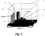
Fig. 2 illustrates the main components of the system. - A typical INS (Inertial Navigation System) normally consists of at least 2 gyroscopes and 3 accelerometers that provide position data. Modern INS are typically of a Strap-Down type - i.e., the gyros and accelerometers are mechanically mounted on the casing of the INS (in contrast to gimbaled sensors). Typical modern gyroscope types may include MEMS (Micro Electro Mechanical Sensors), FOG (Fiber Optic Gyroscope) and RLG (Ring Laser Gyroscope). An INS is capable of providing Position, Velocity and Attitude (PVA) data by manipulating the outputs of Gyros and Accelerometers. When static, the INS initial attitude is acquired by means of a process called gyrocompassing. The gyrocompassing in modern INS systems is based on the calculation of the attitude by measuring the gravity and earth rotation vectors, utilizing the gyros and accelerometers. Once a static system has acquired its initial attitude, the INS uses numerical manipulations of its sensors readouts to track any dynamic changes so as to provide continuous PVA solution. Initial position is either assumed by the system, or supplied externally. Since all sensors are prone to errors, once a system is no longer static and changes are measured relative to the initial state, the inaccuracy of the continuous PVA data drifts with time. Typically for modern systems, GPS signals are used to limit the maximum total error of an INS to constant values, through a process named transfer alignment. GPS, however, is not available underground or inside tunnels and structures and is not effective for tracking small short term movements.
- The present invention comprises a modified North Finding System (NFS), which includes a mono-axial stage, and in which only one of the gyroscopes is a high-precision gyroscope, such as a FOG-based gyroscope. As will be apparent to the skilled person, such high precision gyroscopes are not needed to operate a conventional low-grade INS, and therefore the resulting system, which may be termed a "hybrid" system, is novel both in concept and in operation.
- In one embodiment of the invention, therefore, the system comprises:
- a stage - a rotating platform with a very high precision angular position reading;
- an INS consisting of inertial sensors such as gyroscopes and accelerometers, wherein only one gyroscope is used in the process of finding the direction of true North; and,
- a control unit for controlling input signals and output signals of the stage and the INS and combining the signals in order to ascertain attitude data of the system.
- As explained above, the INS is mounted on a stage and the signals of the high quality and precision gyroscope are used in conjunction with the stage's signals for finding the direction of true North, while the whole system itself is static. Thus, accurate attitude data are ascertained and can be used to initialize the INS and provided to a body to which the system may be attached.
- When the body begins a dynamic inertial maneuver, throughout which the direction of true North seeking ability is no longer available, the whole INS is used to track the inertial momentum changes and ascertain the resulting relative positioning changes from the initially calibrated positioning data. Thus, high accuracy continuous position tracking is achieved both at rest and during movement of various natures for the system and a body to which it may be attached, and this task is performed at low costs and with the use of minimal resources when compared to the prior art.
- With reference now to
Fig. 2 , the main system components are schematically shown.System case 1 defines the axes of the system to which the attitude solution is related. The case may include various accessories for accurate system axes determination (e.g. mirrors 7).Motorized Stage 2 is used for rotating the other components mounted on the rotating disk to predefined angles, and to read the actual rotation angle of the disk relative to the case.High Precision Gyro 3 is of suitable grade to measure the earth rotation rate. Only one such gyro per system is required.Low precision Gyros 4 are used for complementing the High precision gyro to a three axes orthogonal Cartesian system (to cover all three rotational degrees of freedom). ThreeAxes Accelerometers 5 are used for sensing acceleration (specific force) in a three axes orthogonal Cartesian system (to cover all three linear degrees of freedom).Control Computation Unit 6 manages the operation of the motorized stage (1), sensor sampling, algorithms execution and communications. - The process of achieving and maintaining a converged solution of the true north is schematically illustrated in
Fig. 1 . BLOCK 'A' describes the initialization process based on "staged gyro compassing", during which the angular velocity of the Earth (ω), as measured by the higher grade gyro incorporated into the system from several angles, is determined. This process is used to determine the angular deviation (ψ(t)) of the system's case/body to which the case is attached to from the true North (ψ0). That deviation from true north, as estimated in the process describes above, utilizing the system's sensors, can be referred to as "converged solution" (azimuth/heading/...). Performance wise, that solution defines the system's accuracy of North finding. After the initial solution is obtained, is it used as an 'initial condition/continuous reference data' for maintaining it, by using other algorithmic manipulations, as will be described hereinafter (e.g. strap-down navigation and sensor errors estimation algorithms). After those algorithms start running they are kept running for as long as the system operates, even during re-initialization (BLOCK A) which may improve their performance (to be exact, only one initialization is required to start the said algorithms, which are kept running even if and when another north-finding initialization is performed for accuracy improvement). - BLOCK 'B' describes the process of maintaining the converged solution under the assumption of zero movement of the system. Also, a full navigation solution (system attitude and (relative) position) is calculated in the background, utilizing the gyros and accelerometers. The dynamic condition to which the system is exposed is continuously monitored by analyzing the signals obtained from the system's sensors. For as long as there are no dynamic conditions and the system is STATIC [BLOCK 'C'] the solution maintained from the initialization process applies. Once a system movement is detected, the initial condition and the zero movement assumption are held invalid, and the system goes into [BLOCK 'D'].
- Block 'D' describes the system's state at which dynamic conditions are applied to the system, involving velocities and displacements of the system, which render the initial solution invalid. Such dynamics may, for example, originate from an artillery gun when a shot is fired, one of several consecutive firings for example, during which the attitude solution of the system must be maintained regardless of the dynamics involved in such firing. Under applied dynamics, the system's attitude solution is maintained by utilizing the navigation solution kept current to the time of the beginning of the dynamic occurrence in the background, and by continuing that calculation in real time (such as a strapped-down navigation algorithm) an attitude solution is kept valid for as long as the solution's inaccuracy is acceptable, dynamics apply and time permitting. Once an indication for a static condition exists, the system goes into [BLOCK 'E'].
- In block 'E' the current attitude solution's validity is evaluated. During dynamics, and when the assumption of zero movement is not valid, the position and attitude solution of the system is degraded as a function of time. The reason for this time-dependent inaccuracy is output errors inherent to the lower grade sensors (gyros and accelerometers). In a strap-down navigation algorithm for example, it is known for the position solution to diverge relative to the third power of time. Taking the system's error model into account, after a long time of maintaining the solution via algorithms that utilizes the lower grade sensors, the attitude solution's accuracy may be degraded to a level not acceptable by such a system (user and application dependent) and the system may go into [BLOCK 'A'] for a new converged solution calculation as described above. In cases where dynamics apply for relatively short times between consecutive zero movement states of the system (such as but not limited to movement due to gun shots), the suggested system may go back to [BLOCK 'B'] and maintain the attitude solution under the relevant assumptions once again and thus extends the scope of abilities offered by the prior arts, giving a continuous and complete attitude solution under alternating dynamic and static conditions.
- Following the processes described above it is no longer necessary to frequently reinitialize the North finding solution at each and every change of the system state. Of course, time permitting it may be desirable periodically to recalibrate (initialization, block 'A') the system by performing a full North finding procedure, in order to improve the system's accuracy.
- As will be appreciated by the skilled person the invention provides a simple and inexpensive way to overcome the drawbacks of the prior art. Of course, the above description has been given for the purpose of illustration and is not meant to limit the invention in any way, except as defined in the claims to follow.
Claims (8)
- A hybrid attitude determination system which is provided within a casing (1) that is attachable to a body, the system being provided with true-North-finding capability, comprising:a) a North finding unit which comprises only one high precision gyroscope (3) and at least one accelerometer (5), and a North finding calculation means (6);b) an INS unit which comprises, as an integral part, said only one high precision gyroscope (3) and at least one accelerometer (5) of said North finding unit, and which further comprises additional gyroscopes (4) and one or more additional accelerometers (5) that complement said INS unit to include a total of three gyroscopes (3, 4) that are perpendicular to each other and three accelerometers (5) that are perpendicular to each other, said INS unit further comprising an INS calculation means (6);c) a rotating stage (2) on which the gyroscopes (3, 4) and the accelerometers (5) of the North finding unit and the INS unit are mounted;wherein during a static state of the casing (1), the attitude determination system is configured to output attitude, namely, true heading, pitch and roll, relative to the North as calculated by said North finding calculation algorithm (6), while said North finding unit is configured to further provide during said static state of the casing (1) initial conditions to said INS unit;
wherein during a dynamic state of the casing (1), said attitude determination system is configured to output attitude direction as calculated by said INS calculation algorithm (6) of said INS unit, by using said initial conditions as provided from said North finding unit. - The system according to claim 1, wherein during a dynamic state of the casing (1), the INS unit is configured to further output velocity and position of the casing.
- The system according to claim 1, wherein transfers from a static state of the casing (1) to a dynamic state of the casing (1), or from a dynamic state of the casing (1) to a static state of the casing (1), are determined by said INS sensors (3, 4, 5).
- The system according to claim 1, further comprising a monitoring unit which is configured to verify validity of the attitude determination, and upon detection of poor accuracy, the system is configured to perform, a static-state initialization which involves new determination of the true North by the North finding unit.
- A hybrid method for determining a true North and attitude during static and dynamic states of a body, which comprises:a) providing a North finding unit, which comprises only one high precision gyroscope and at least one accelerometer, and a North finding calculation means;b) providing an INS unit, which comprises, as an integral part, said only one high precision gyroscope and at least one accelerometer of said North finding unit, and which further comprises additional gyroscopes and one or more additional accelerometers that complement said INS unit to include a total of three gyroscopes that are perpendicular to each other and three accelerometers that are perpendicular to each other, and which further comprises an INS calculation means;c) providing a rotating stage on which the gyroscopes and the accelerometers of the North finding unit and the INS unit are mounted;d) during a static state of the body, calculating and determining by said North finding calculation algorithm an attitude relative to the North, and further providing to said INS unit during said static state said determined attitude relative to the North as an initial condition; ande) during a dynamic state of the body, calculating and determining by said calculation algorithm of said INS unit an attitude direction, by using in said calculation the initial conditions as provided by said North finding unit.
- The method according to claim 5, further determining by the INS unit the position and velocity of the body.
- The method according to claim 5, further determining transfers from a static state of the body to a dynamic state of the body, or from a dynamic state of the body to a static state of the body, by using the sensors of the INS unit.
- The method according to claim 5, further comprising a step of monitoring and verifying the validity of the attitude determination, and upon detection of a poor accuracy, performing a static-state initialization, which involves new determination of the true North by the North finding unit.
Applications Claiming Priority (2)
| Application Number | Priority Date | Filing Date | Title |
|---|---|---|---|
| IL206459A IL206459A (en) | 2010-06-17 | 2010-06-17 | North finder |
| PCT/IL2011/000466 WO2011158228A1 (en) | 2010-06-17 | 2011-06-13 | Improved north finder |
Publications (3)
| Publication Number | Publication Date |
|---|---|
| EP2583059A1 EP2583059A1 (en) | 2013-04-24 |
| EP2583059A4 EP2583059A4 (en) | 2015-03-18 |
| EP2583059B1 true EP2583059B1 (en) | 2019-08-07 |
Family
ID=43569910
Family Applications (1)
| Application Number | Title | Priority Date | Filing Date |
|---|---|---|---|
| EP11795293.7A Active EP2583059B1 (en) | 2010-06-17 | 2011-06-13 | Improved north finder |
Country Status (5)
| Country | Link |
|---|---|
| US (1) | US8930138B2 (en) |
| EP (1) | EP2583059B1 (en) |
| IL (1) | IL206459A (en) |
| SG (1) | SG186362A1 (en) |
| WO (1) | WO2011158228A1 (en) |
Families Citing this family (13)
| Publication number | Priority date | Publication date | Assignee | Title |
|---|---|---|---|---|
| IL222221B (en) | 2012-09-27 | 2019-03-31 | Rafael Advanced Defense Systems Ltd | Improved inertial navigation system and method |
| CN103344226B (en) * | 2013-06-27 | 2015-11-18 | 南京航空航天大学 | A kind of north-seeking system based on MEMS rotation technique and method |
| CN103968840B (en) * | 2014-05-22 | 2017-01-25 | 北京航天控制仪器研究所 | All-digital control platform type inertial navigation system |
| CN104215241B (en) * | 2014-09-02 | 2017-07-04 | 常州巴乌克智能科技有限公司 | Inertial Sensor Unit |
| CN104236586B (en) * | 2014-09-05 | 2017-02-08 | 南京理工大学 | Moving base transfer alignment method based on measurement of misalignment angle |
| CN104634346B (en) * | 2015-02-13 | 2017-04-19 | 西安应用光学研究所 | Gesture detection method for photoelectric platform based on fiber-optic gyroscopes |
| CN111366144B (en) * | 2019-11-26 | 2023-07-28 | 北京计算机技术及应用研究所 | Multi-position north-seeking method for gyro north-seeking instrument |
| CN110926447B (en) * | 2019-12-16 | 2022-02-22 | 重庆华渝电气集团有限公司 | Single-axis fiber-optic gyroscope north-seeking method with autonomous navigation function and attitude navigation method |
| CN112484712B (en) * | 2020-11-23 | 2022-08-12 | 重庆华渝电气集团有限公司 | Double-gyroscope north-seeking attitude reference instrument and north-seeking method |
| CN112556674B (en) * | 2020-12-03 | 2022-05-31 | 北京北寻融科科技有限公司 | Micro-inertia north seeker |
| CN112964240B (en) * | 2021-02-20 | 2023-08-08 | 广州导远电子科技有限公司 | Continuous north-seeking device and method, electronic equipment and storage medium |
| CN113984033A (en) * | 2021-10-18 | 2022-01-28 | 华中光电技术研究所(中国船舶重工集团公司第七一七研究所) | North seeking method and system based on four-pulse atomic interference gyroscope |
| CN114322970B (en) * | 2021-11-30 | 2024-01-12 | 湖南航天机电设备与特种材料研究所 | Dual gyroscope north-seeking method, system and storage medium |
Citations (1)
| Publication number | Priority date | Publication date | Assignee | Title |
|---|---|---|---|---|
| US20090070058A1 (en) * | 2007-08-14 | 2009-03-12 | American Gnc Corporation | Miniaturized smart self-calibration electronic pointing method and system |
Family Cites Families (7)
| Publication number | Priority date | Publication date | Assignee | Title |
|---|---|---|---|---|
| US5272922A (en) | 1991-03-06 | 1993-12-28 | Watson Industries, Inc. | Vibrating element angular rate sensor system and north seeking gyroscope embodiment thereof |
| US5617317A (en) | 1995-01-24 | 1997-04-01 | Honeywell Inc. | True north heading estimator utilizing GPS output information and inertial sensor system output information |
| US20030135327A1 (en) | 2002-01-11 | 2003-07-17 | Seymour Levine | Low cost inertial navigator |
| US8239162B2 (en) * | 2006-04-13 | 2012-08-07 | Tanenhaus & Associates, Inc. | Miniaturized inertial measurement unit and associated methods |
| US7412775B1 (en) | 2007-08-03 | 2008-08-19 | Honeywell International Inc. | Gyroscope north seeker system and method |
| US8005635B2 (en) | 2007-08-14 | 2011-08-23 | Ching-Fang Lin | Self-calibrated azimuth and attitude accuracy enhancing method and system (SAAAEMS) |
| IL198109A (en) | 2009-04-07 | 2013-01-31 | Azimuth Technologies Ltd | North finding device, system and method |
-
2010
- 2010-06-17 IL IL206459A patent/IL206459A/en active IP Right Grant
-
2011
- 2011-06-13 US US13/704,445 patent/US8930138B2/en active Active
- 2011-06-13 EP EP11795293.7A patent/EP2583059B1/en active Active
- 2011-06-13 WO PCT/IL2011/000466 patent/WO2011158228A1/en active Application Filing
- 2011-06-13 SG SG2012092292A patent/SG186362A1/en unknown
Patent Citations (1)
| Publication number | Priority date | Publication date | Assignee | Title |
|---|---|---|---|---|
| US20090070058A1 (en) * | 2007-08-14 | 2009-03-12 | American Gnc Corporation | Miniaturized smart self-calibration electronic pointing method and system |
Also Published As
| Publication number | Publication date |
|---|---|
| US20130090848A1 (en) | 2013-04-11 |
| WO2011158228A1 (en) | 2011-12-22 |
| EP2583059A1 (en) | 2013-04-24 |
| IL206459A0 (en) | 2010-12-30 |
| SG186362A1 (en) | 2013-01-30 |
| IL206459A (en) | 2015-11-30 |
| EP2583059A4 (en) | 2015-03-18 |
| US8930138B2 (en) | 2015-01-06 |
Similar Documents
| Publication | Publication Date | Title |
|---|---|---|
| EP2583059B1 (en) | Improved north finder | |
| US10132634B2 (en) | Inertial navigation system and method | |
| US8311757B2 (en) | Miniaturized smart self-calibration electronic pointing method and system | |
| US8005635B2 (en) | Self-calibrated azimuth and attitude accuracy enhancing method and system (SAAAEMS) | |
| US6459990B1 (en) | Self-contained positioning method and system thereof for water and land vehicles | |
| CA2694455C (en) | North finding device, system and method | |
| US8521428B1 (en) | Heading determination using sensors mounted on rotatable assembly | |
| Bezick et al. | Inertial navigation for guided missile systems | |
| CN101839719A (en) | Inertial measurement unit based on gyroscope and geomagnetic sensor | |
| CN102257358A (en) | Method for determining a heading in the direction of true north using an inertial measurement unit | |
| CN110621961B (en) | Low cost inertial navigation system | |
| US20140249750A1 (en) | Navigational and location determination system | |
| Noureldin et al. | Inertial navigation system | |
| US10006770B2 (en) | Remote location determination system | |
| Braasch | Inertial navigation systems | |
| RU2624617C1 (en) | Method for autonomous azimuthal orienting three-axis gyrostabilizer platform by changing visibile drifts | |
| Avrutov et al. | Strapdown Gyro Latitude Finder | |
| KR101519431B1 (en) | Azimuth providing apparatus | |
| US3545092A (en) | Method for aligning a navigation system | |
| RU2732520C1 (en) | Device for determination of spatial orientation of soyuz-2 space rocket | |
| US20230204358A1 (en) | Mems gyrocompass | |
| Stanisak | „Inertial Technology: Sensors, Algorithms, and Integration,“ | |
| CN117705097A (en) | Prism rod device, ground object broken point measuring method, device and medium | |
| Erdemir et al. | Real time roll angle estimation for fast spinning projectiles | |
| Bar-Itzhack et al. | New inertial azimuth finder apparatus |
Legal Events
| Date | Code | Title | Description |
|---|---|---|---|
| PUAI | Public reference made under article 153(3) epc to a published international application that has entered the european phase |
Free format text: ORIGINAL CODE: 0009012 |
|
| 17P | Request for examination filed |
Effective date: 20121228 |
|
| AK | Designated contracting states |
Kind code of ref document: A1 Designated state(s): AL AT BE BG CH CY CZ DE DK EE ES FI FR GB GR HR HU IE IS IT LI LT LU LV MC MK MT NL NO PL PT RO RS SE SI SK SM TR |
|
| DAX | Request for extension of the european patent (deleted) | ||
| A4 | Supplementary search report drawn up and despatched |
Effective date: 20150212 |
|
| RIC1 | Information provided on ipc code assigned before grant |
Ipc: G01C 19/36 20060101AFI20150206BHEP Ipc: G01C 21/16 20060101ALI20150206BHEP |
|
| STAA | Information on the status of an ep patent application or granted ep patent |
Free format text: STATUS: EXAMINATION IS IN PROGRESS |
|
| 17Q | First examination report despatched |
Effective date: 20161115 |
|
| REG | Reference to a national code |
Ref country code: DE Ref legal event code: R079 Ref document number: 602011061096 Country of ref document: DE Free format text: PREVIOUS MAIN CLASS: G01C0019360000 Ipc: G01C0019380000 |
|
| RIC1 | Information provided on ipc code assigned before grant |
Ipc: G01C 19/42 20060101ALI20181212BHEP Ipc: G01C 21/16 20060101ALI20181212BHEP Ipc: G01C 19/38 20060101AFI20181212BHEP |
|
| GRAP | Despatch of communication of intention to grant a patent |
Free format text: ORIGINAL CODE: EPIDOSNIGR1 |
|
| STAA | Information on the status of an ep patent application or granted ep patent |
Free format text: STATUS: GRANT OF PATENT IS INTENDED |
|
| INTG | Intention to grant announced |
Effective date: 20190318 |
|
| GRAS | Grant fee paid |
Free format text: ORIGINAL CODE: EPIDOSNIGR3 |
|
| GRAA | (expected) grant |
Free format text: ORIGINAL CODE: 0009210 |
|
| STAA | Information on the status of an ep patent application or granted ep patent |
Free format text: STATUS: THE PATENT HAS BEEN GRANTED |
|
| AK | Designated contracting states |
Kind code of ref document: B1 Designated state(s): AL AT BE BG CH CY CZ DE DK EE ES FI FR GB GR HR HU IE IS IT LI LT LU LV MC MK MT NL NO PL PT RO RS SE SI SK SM TR |
|
| REG | Reference to a national code |
Ref country code: GB Ref legal event code: FG4D |
|
| REG | Reference to a national code |
Ref country code: CH Ref legal event code: EP Ref country code: AT Ref legal event code: REF Ref document number: 1164559 Country of ref document: AT Kind code of ref document: T Effective date: 20190815 |
|
| REG | Reference to a national code |
Ref country code: DE Ref legal event code: R096 Ref document number: 602011061096 Country of ref document: DE |
|
| REG | Reference to a national code |
Ref country code: IE Ref legal event code: FG4D |
|
| REG | Reference to a national code |
Ref country code: NL Ref legal event code: MP Effective date: 20190807 |
|
| REG | Reference to a national code |
Ref country code: LT Ref legal event code: MG4D |
|
| PG25 | Lapsed in a contracting state [announced via postgrant information from national office to epo] |
Ref country code: FI Free format text: LAPSE BECAUSE OF FAILURE TO SUBMIT A TRANSLATION OF THE DESCRIPTION OR TO PAY THE FEE WITHIN THE PRESCRIBED TIME-LIMIT Effective date: 20190807 Ref country code: LT Free format text: LAPSE BECAUSE OF FAILURE TO SUBMIT A TRANSLATION OF THE DESCRIPTION OR TO PAY THE FEE WITHIN THE PRESCRIBED TIME-LIMIT Effective date: 20190807 Ref country code: HR Free format text: LAPSE BECAUSE OF FAILURE TO SUBMIT A TRANSLATION OF THE DESCRIPTION OR TO PAY THE FEE WITHIN THE PRESCRIBED TIME-LIMIT Effective date: 20190807 Ref country code: PT Free format text: LAPSE BECAUSE OF FAILURE TO SUBMIT A TRANSLATION OF THE DESCRIPTION OR TO PAY THE FEE WITHIN THE PRESCRIBED TIME-LIMIT Effective date: 20191209 Ref country code: BG Free format text: LAPSE BECAUSE OF FAILURE TO SUBMIT A TRANSLATION OF THE DESCRIPTION OR TO PAY THE FEE WITHIN THE PRESCRIBED TIME-LIMIT Effective date: 20191107 Ref country code: NO Free format text: LAPSE BECAUSE OF FAILURE TO SUBMIT A TRANSLATION OF THE DESCRIPTION OR TO PAY THE FEE WITHIN THE PRESCRIBED TIME-LIMIT Effective date: 20191107 Ref country code: NL Free format text: LAPSE BECAUSE OF FAILURE TO SUBMIT A TRANSLATION OF THE DESCRIPTION OR TO PAY THE FEE WITHIN THE PRESCRIBED TIME-LIMIT Effective date: 20190807 Ref country code: SE Free format text: LAPSE BECAUSE OF FAILURE TO SUBMIT A TRANSLATION OF THE DESCRIPTION OR TO PAY THE FEE WITHIN THE PRESCRIBED TIME-LIMIT Effective date: 20190807 |
|
| REG | Reference to a national code |
Ref country code: AT Ref legal event code: MK05 Ref document number: 1164559 Country of ref document: AT Kind code of ref document: T Effective date: 20190807 |
|
| PG25 | Lapsed in a contracting state [announced via postgrant information from national office to epo] |
Ref country code: GR Free format text: LAPSE BECAUSE OF FAILURE TO SUBMIT A TRANSLATION OF THE DESCRIPTION OR TO PAY THE FEE WITHIN THE PRESCRIBED TIME-LIMIT Effective date: 20191108 Ref country code: ES Free format text: LAPSE BECAUSE OF FAILURE TO SUBMIT A TRANSLATION OF THE DESCRIPTION OR TO PAY THE FEE WITHIN THE PRESCRIBED TIME-LIMIT Effective date: 20190807 Ref country code: IS Free format text: LAPSE BECAUSE OF FAILURE TO SUBMIT A TRANSLATION OF THE DESCRIPTION OR TO PAY THE FEE WITHIN THE PRESCRIBED TIME-LIMIT Effective date: 20191207 Ref country code: RS Free format text: LAPSE BECAUSE OF FAILURE TO SUBMIT A TRANSLATION OF THE DESCRIPTION OR TO PAY THE FEE WITHIN THE PRESCRIBED TIME-LIMIT Effective date: 20190807 Ref country code: LV Free format text: LAPSE BECAUSE OF FAILURE TO SUBMIT A TRANSLATION OF THE DESCRIPTION OR TO PAY THE FEE WITHIN THE PRESCRIBED TIME-LIMIT Effective date: 20190807 Ref country code: AL Free format text: LAPSE BECAUSE OF FAILURE TO SUBMIT A TRANSLATION OF THE DESCRIPTION OR TO PAY THE FEE WITHIN THE PRESCRIBED TIME-LIMIT Effective date: 20190807 |
|
| PG25 | Lapsed in a contracting state [announced via postgrant information from national office to epo] |
Ref country code: TR Free format text: LAPSE BECAUSE OF FAILURE TO SUBMIT A TRANSLATION OF THE DESCRIPTION OR TO PAY THE FEE WITHIN THE PRESCRIBED TIME-LIMIT Effective date: 20190807 |
|
| PG25 | Lapsed in a contracting state [announced via postgrant information from national office to epo] |
Ref country code: AT Free format text: LAPSE BECAUSE OF FAILURE TO SUBMIT A TRANSLATION OF THE DESCRIPTION OR TO PAY THE FEE WITHIN THE PRESCRIBED TIME-LIMIT Effective date: 20190807 Ref country code: DK Free format text: LAPSE BECAUSE OF FAILURE TO SUBMIT A TRANSLATION OF THE DESCRIPTION OR TO PAY THE FEE WITHIN THE PRESCRIBED TIME-LIMIT Effective date: 20190807 Ref country code: RO Free format text: LAPSE BECAUSE OF FAILURE TO SUBMIT A TRANSLATION OF THE DESCRIPTION OR TO PAY THE FEE WITHIN THE PRESCRIBED TIME-LIMIT Effective date: 20190807 Ref country code: EE Free format text: LAPSE BECAUSE OF FAILURE TO SUBMIT A TRANSLATION OF THE DESCRIPTION OR TO PAY THE FEE WITHIN THE PRESCRIBED TIME-LIMIT Effective date: 20190807 Ref country code: PL Free format text: LAPSE BECAUSE OF FAILURE TO SUBMIT A TRANSLATION OF THE DESCRIPTION OR TO PAY THE FEE WITHIN THE PRESCRIBED TIME-LIMIT Effective date: 20190807 |
|
| PG25 | Lapsed in a contracting state [announced via postgrant information from national office to epo] |
Ref country code: SK Free format text: LAPSE BECAUSE OF FAILURE TO SUBMIT A TRANSLATION OF THE DESCRIPTION OR TO PAY THE FEE WITHIN THE PRESCRIBED TIME-LIMIT Effective date: 20190807 Ref country code: SM Free format text: LAPSE BECAUSE OF FAILURE TO SUBMIT A TRANSLATION OF THE DESCRIPTION OR TO PAY THE FEE WITHIN THE PRESCRIBED TIME-LIMIT Effective date: 20190807 Ref country code: IS Free format text: LAPSE BECAUSE OF FAILURE TO SUBMIT A TRANSLATION OF THE DESCRIPTION OR TO PAY THE FEE WITHIN THE PRESCRIBED TIME-LIMIT Effective date: 20200224 Ref country code: CZ Free format text: LAPSE BECAUSE OF FAILURE TO SUBMIT A TRANSLATION OF THE DESCRIPTION OR TO PAY THE FEE WITHIN THE PRESCRIBED TIME-LIMIT Effective date: 20190807 |
|
| REG | Reference to a national code |
Ref country code: DE Ref legal event code: R097 Ref document number: 602011061096 Country of ref document: DE |
|
| PLBE | No opposition filed within time limit |
Free format text: ORIGINAL CODE: 0009261 |
|
| STAA | Information on the status of an ep patent application or granted ep patent |
Free format text: STATUS: NO OPPOSITION FILED WITHIN TIME LIMIT |
|
| PG2D | Information on lapse in contracting state deleted |
Ref country code: IS |
|
| 26N | No opposition filed |
Effective date: 20200603 |
|
| PG25 | Lapsed in a contracting state [announced via postgrant information from national office to epo] |
Ref country code: SI Free format text: LAPSE BECAUSE OF FAILURE TO SUBMIT A TRANSLATION OF THE DESCRIPTION OR TO PAY THE FEE WITHIN THE PRESCRIBED TIME-LIMIT Effective date: 20190807 |
|
| PG25 | Lapsed in a contracting state [announced via postgrant information from national office to epo] |
Ref country code: MC Free format text: LAPSE BECAUSE OF FAILURE TO SUBMIT A TRANSLATION OF THE DESCRIPTION OR TO PAY THE FEE WITHIN THE PRESCRIBED TIME-LIMIT Effective date: 20190807 |
|
| REG | Reference to a national code |
Ref country code: CH Ref legal event code: PL |
|
| PG25 | Lapsed in a contracting state [announced via postgrant information from national office to epo] |
Ref country code: LU Free format text: LAPSE BECAUSE OF NON-PAYMENT OF DUE FEES Effective date: 20200613 |
|
| REG | Reference to a national code |
Ref country code: BE Ref legal event code: MM Effective date: 20200630 |
|
| PG25 | Lapsed in a contracting state [announced via postgrant information from national office to epo] |
Ref country code: CH Free format text: LAPSE BECAUSE OF NON-PAYMENT OF DUE FEES Effective date: 20200630 Ref country code: LI Free format text: LAPSE BECAUSE OF NON-PAYMENT OF DUE FEES Effective date: 20200630 Ref country code: IE Free format text: LAPSE BECAUSE OF NON-PAYMENT OF DUE FEES Effective date: 20200613 |
|
| PG25 | Lapsed in a contracting state [announced via postgrant information from national office to epo] |
Ref country code: BE Free format text: LAPSE BECAUSE OF NON-PAYMENT OF DUE FEES Effective date: 20200630 |
|
| PG25 | Lapsed in a contracting state [announced via postgrant information from national office to epo] |
Ref country code: MT Free format text: LAPSE BECAUSE OF FAILURE TO SUBMIT A TRANSLATION OF THE DESCRIPTION OR TO PAY THE FEE WITHIN THE PRESCRIBED TIME-LIMIT Effective date: 20190807 Ref country code: CY Free format text: LAPSE BECAUSE OF FAILURE TO SUBMIT A TRANSLATION OF THE DESCRIPTION OR TO PAY THE FEE WITHIN THE PRESCRIBED TIME-LIMIT Effective date: 20190807 |
|
| PG25 | Lapsed in a contracting state [announced via postgrant information from national office to epo] |
Ref country code: MK Free format text: LAPSE BECAUSE OF FAILURE TO SUBMIT A TRANSLATION OF THE DESCRIPTION OR TO PAY THE FEE WITHIN THE PRESCRIBED TIME-LIMIT Effective date: 20190807 |
|
| REG | Reference to a national code |
Ref country code: FR Ref legal event code: PLFP Year of fee payment: 13 |
|
| P01 | Opt-out of the competence of the unified patent court (upc) registered |
Effective date: 20230517 |
|
| PGFP | Annual fee paid to national office [announced via postgrant information from national office to epo] |
Ref country code: IT Payment date: 20230510 Year of fee payment: 13 Ref country code: FR Payment date: 20230411 Year of fee payment: 13 Ref country code: DE Payment date: 20230418 Year of fee payment: 13 |
|
| PGFP | Annual fee paid to national office [announced via postgrant information from national office to epo] |
Ref country code: GB Payment date: 20230420 Year of fee payment: 13 |