EP1983604A2 - Wireless communication device and method - Google Patents
Wireless communication device and method Download PDFInfo
- Publication number
- EP1983604A2 EP1983604A2 EP08005267A EP08005267A EP1983604A2 EP 1983604 A2 EP1983604 A2 EP 1983604A2 EP 08005267 A EP08005267 A EP 08005267A EP 08005267 A EP08005267 A EP 08005267A EP 1983604 A2 EP1983604 A2 EP 1983604A2
- Authority
- EP
- European Patent Office
- Prior art keywords
- shaped
- wave antenna
- wireless communication
- polygonal
- conductor
- Prior art date
- Legal status (The legal status is an assumption and is not a legal conclusion. Google has not performed a legal analysis and makes no representation as to the accuracy of the status listed.)
- Withdrawn
Links
- 238000004891 communication Methods 0.000 title claims abstract description 354
- 238000000034 method Methods 0.000 title claims description 49
- 238000004519 manufacturing process Methods 0.000 claims abstract description 52
- 239000004020 conductor Substances 0.000 claims description 219
- 238000005476 soldering Methods 0.000 claims description 33
- 239000011888 foil Substances 0.000 claims description 29
- 230000005404 monopole Effects 0.000 claims description 18
- 230000007613 environmental effect Effects 0.000 claims description 17
- 229910000679 solder Inorganic materials 0.000 claims description 17
- 238000004140 cleaning Methods 0.000 claims description 9
- 230000008859 change Effects 0.000 claims description 8
- 230000001939 inductive effect Effects 0.000 claims description 5
- 239000012811 non-conductive material Substances 0.000 claims description 5
- 230000000694 effects Effects 0.000 claims description 3
- 238000010586 diagram Methods 0.000 description 75
- 230000008569 process Effects 0.000 description 23
- 239000000463 material Substances 0.000 description 11
- 230000008878 coupling Effects 0.000 description 8
- 238000010168 coupling process Methods 0.000 description 8
- 238000005859 coupling reaction Methods 0.000 description 8
- 230000004044 response Effects 0.000 description 6
- ATJFFYVFTNAWJD-UHFFFAOYSA-N Tin Chemical compound [Sn] ATJFFYVFTNAWJD-UHFFFAOYSA-N 0.000 description 5
- 230000006835 compression Effects 0.000 description 5
- 238000007906 compression Methods 0.000 description 5
- 238000013461 design Methods 0.000 description 5
- 238000012986 modification Methods 0.000 description 4
- 230000004048 modification Effects 0.000 description 4
- 229910001369 Brass Inorganic materials 0.000 description 3
- 229910000831 Steel Inorganic materials 0.000 description 3
- 239000000853 adhesive Substances 0.000 description 3
- 230000001070 adhesive effect Effects 0.000 description 3
- 239000010951 brass Substances 0.000 description 3
- 238000006880 cross-coupling reaction Methods 0.000 description 3
- 239000010959 steel Substances 0.000 description 3
- 238000010998 test method Methods 0.000 description 3
- 238000012546 transfer Methods 0.000 description 3
- 239000004593 Epoxy Substances 0.000 description 2
- 239000003990 capacitor Substances 0.000 description 2
- 230000008602 contraction Effects 0.000 description 2
- 238000009826 distribution Methods 0.000 description 2
- 230000006872 improvement Effects 0.000 description 2
- 230000003993 interaction Effects 0.000 description 2
- RYGMFSIKBFXOCR-UHFFFAOYSA-N Copper Chemical compound [Cu] RYGMFSIKBFXOCR-UHFFFAOYSA-N 0.000 description 1
- 229910000639 Spring steel Inorganic materials 0.000 description 1
- 230000009471 action Effects 0.000 description 1
- 238000005452 bending Methods 0.000 description 1
- 230000009286 beneficial effect Effects 0.000 description 1
- 230000008901 benefit Effects 0.000 description 1
- 239000006229 carbon black Substances 0.000 description 1
- 239000011248 coating agent Substances 0.000 description 1
- 238000000576 coating method Methods 0.000 description 1
- 238000010276 construction Methods 0.000 description 1
- 229910052802 copper Inorganic materials 0.000 description 1
- 239000010949 copper Substances 0.000 description 1
- 238000001514 detection method Methods 0.000 description 1
- 239000003292 glue Substances 0.000 description 1
- 230000006698 induction Effects 0.000 description 1
- 239000011810 insulating material Substances 0.000 description 1
- 230000001788 irregular Effects 0.000 description 1
- 238000003475 lamination Methods 0.000 description 1
- 230000007246 mechanism Effects 0.000 description 1
- 239000002184 metal Substances 0.000 description 1
- 229910052751 metal Inorganic materials 0.000 description 1
- 238000012544 monitoring process Methods 0.000 description 1
- 230000006855 networking Effects 0.000 description 1
- 230000000737 periodic effect Effects 0.000 description 1
- 239000004033 plastic Substances 0.000 description 1
- 238000003908 quality control method Methods 0.000 description 1
- 238000003860 storage Methods 0.000 description 1
- 239000000126 substance Substances 0.000 description 1
- 238000013068 supply chain management Methods 0.000 description 1
- 238000003466 welding Methods 0.000 description 1
- 238000004804 winding Methods 0.000 description 1
Images


Classifications
-
- H—ELECTRICITY
- H04—ELECTRIC COMMUNICATION TECHNIQUE
- H04B—TRANSMISSION
- H04B5/00—Near-field transmission systems, e.g. inductive or capacitive transmission systems
- H04B5/40—Near-field transmission systems, e.g. inductive or capacitive transmission systems characterised by components specially adapted for near-field transmission
- H04B5/48—Transceivers
-
- H—ELECTRICITY
- H01—ELECTRIC ELEMENTS
- H01Q—ANTENNAS, i.e. RADIO AERIALS
- H01Q9/00—Electrically-short antennas having dimensions not more than twice the operating wavelength and consisting of conductive active radiating elements
- H01Q9/04—Resonant antennas
- H01Q9/16—Resonant antennas with feed intermediate between the extremities of the antenna, e.g. centre-fed dipole
-
- B—PERFORMING OPERATIONS; TRANSPORTING
- B60—VEHICLES IN GENERAL
- B60C—VEHICLE TYRES; TYRE INFLATION; TYRE CHANGING; CONNECTING VALVES TO INFLATABLE ELASTIC BODIES IN GENERAL; DEVICES OR ARRANGEMENTS RELATED TO TYRES
- B60C23/00—Devices for measuring, signalling, controlling, or distributing tyre pressure or temperature, specially adapted for mounting on vehicles; Arrangement of tyre inflating devices on vehicles, e.g. of pumps or of tanks; Tyre cooling arrangements
- B60C23/02—Signalling devices actuated by tyre pressure
- B60C23/04—Signalling devices actuated by tyre pressure mounted on the wheel or tyre
- B60C23/0408—Signalling devices actuated by tyre pressure mounted on the wheel or tyre transmitting the signals by non-mechanical means from the wheel or tyre to a vehicle body mounted receiver
- B60C23/0422—Signalling devices actuated by tyre pressure mounted on the wheel or tyre transmitting the signals by non-mechanical means from the wheel or tyre to a vehicle body mounted receiver characterised by the type of signal transmission means
- B60C23/0433—Radio signals
- B60C23/0447—Wheel or tyre mounted circuits
- B60C23/0452—Antenna structure, control or arrangement
-
- G—PHYSICS
- G06—COMPUTING; CALCULATING OR COUNTING
- G06K—GRAPHICAL DATA READING; PRESENTATION OF DATA; RECORD CARRIERS; HANDLING RECORD CARRIERS
- G06K19/00—Record carriers for use with machines and with at least a part designed to carry digital markings
- G06K19/06—Record carriers for use with machines and with at least a part designed to carry digital markings characterised by the kind of the digital marking, e.g. shape, nature, code
- G06K19/067—Record carriers with conductive marks, printed circuits or semiconductor circuit elements, e.g. credit or identity cards also with resonating or responding marks without active components
- G06K19/07—Record carriers with conductive marks, printed circuits or semiconductor circuit elements, e.g. credit or identity cards also with resonating or responding marks without active components with integrated circuit chips
- G06K19/077—Constructional details, e.g. mounting of circuits in the carrier
- G06K19/07749—Constructional details, e.g. mounting of circuits in the carrier the record carrier being capable of non-contact communication, e.g. constructional details of the antenna of a non-contact smart card
- G06K19/07758—Constructional details, e.g. mounting of circuits in the carrier the record carrier being capable of non-contact communication, e.g. constructional details of the antenna of a non-contact smart card arrangements for adhering the record carrier to further objects or living beings, functioning as an identification tag
- G06K19/07764—Constructional details, e.g. mounting of circuits in the carrier the record carrier being capable of non-contact communication, e.g. constructional details of the antenna of a non-contact smart card arrangements for adhering the record carrier to further objects or living beings, functioning as an identification tag the adhering arrangement making the record carrier attachable to a tire
-
- G—PHYSICS
- G06—COMPUTING; CALCULATING OR COUNTING
- G06K—GRAPHICAL DATA READING; PRESENTATION OF DATA; RECORD CARRIERS; HANDLING RECORD CARRIERS
- G06K19/00—Record carriers for use with machines and with at least a part designed to carry digital markings
- G06K19/06—Record carriers for use with machines and with at least a part designed to carry digital markings characterised by the kind of the digital marking, e.g. shape, nature, code
- G06K19/067—Record carriers with conductive marks, printed circuits or semiconductor circuit elements, e.g. credit or identity cards also with resonating or responding marks without active components
- G06K19/07—Record carriers with conductive marks, printed circuits or semiconductor circuit elements, e.g. credit or identity cards also with resonating or responding marks without active components with integrated circuit chips
- G06K19/077—Constructional details, e.g. mounting of circuits in the carrier
- G06K19/07749—Constructional details, e.g. mounting of circuits in the carrier the record carrier being capable of non-contact communication, e.g. constructional details of the antenna of a non-contact smart card
- G06K19/07773—Antenna details
- G06K19/07786—Antenna details the antenna being of the HF type, such as a dipole
-
- H—ELECTRICITY
- H01—ELECTRIC ELEMENTS
- H01Q—ANTENNAS, i.e. RADIO AERIALS
- H01Q1/00—Details of, or arrangements associated with, antennas
- H01Q1/12—Supports; Mounting means
- H01Q1/22—Supports; Mounting means by structural association with other equipment or articles
- H01Q1/2208—Supports; Mounting means by structural association with other equipment or articles associated with components used in interrogation type services, i.e. in systems for information exchange between an interrogator/reader and a tag/transponder, e.g. in Radio Frequency Identification [RFID] systems
- H01Q1/2216—Supports; Mounting means by structural association with other equipment or articles associated with components used in interrogation type services, i.e. in systems for information exchange between an interrogator/reader and a tag/transponder, e.g. in Radio Frequency Identification [RFID] systems used in interrogator/reader equipment
-
- H—ELECTRICITY
- H01—ELECTRIC ELEMENTS
- H01Q—ANTENNAS, i.e. RADIO AERIALS
- H01Q1/00—Details of, or arrangements associated with, antennas
- H01Q1/12—Supports; Mounting means
- H01Q1/22—Supports; Mounting means by structural association with other equipment or articles
- H01Q1/2208—Supports; Mounting means by structural association with other equipment or articles associated with components used in interrogation type services, i.e. in systems for information exchange between an interrogator/reader and a tag/transponder, e.g. in Radio Frequency Identification [RFID] systems
- H01Q1/2225—Supports; Mounting means by structural association with other equipment or articles associated with components used in interrogation type services, i.e. in systems for information exchange between an interrogator/reader and a tag/transponder, e.g. in Radio Frequency Identification [RFID] systems used in active tags, i.e. provided with its own power source or in passive tags, i.e. deriving power from RF signal
-
- H—ELECTRICITY
- H01—ELECTRIC ELEMENTS
- H01Q—ANTENNAS, i.e. RADIO AERIALS
- H01Q1/00—Details of, or arrangements associated with, antennas
- H01Q1/12—Supports; Mounting means
- H01Q1/22—Supports; Mounting means by structural association with other equipment or articles
- H01Q1/2208—Supports; Mounting means by structural association with other equipment or articles associated with components used in interrogation type services, i.e. in systems for information exchange between an interrogator/reader and a tag/transponder, e.g. in Radio Frequency Identification [RFID] systems
- H01Q1/2241—Supports; Mounting means by structural association with other equipment or articles associated with components used in interrogation type services, i.e. in systems for information exchange between an interrogator/reader and a tag/transponder, e.g. in Radio Frequency Identification [RFID] systems used in or for vehicle tyres
-
- H—ELECTRICITY
- H01—ELECTRIC ELEMENTS
- H01Q—ANTENNAS, i.e. RADIO AERIALS
- H01Q1/00—Details of, or arrangements associated with, antennas
- H01Q1/12—Supports; Mounting means
- H01Q1/22—Supports; Mounting means by structural association with other equipment or articles
- H01Q1/24—Supports; Mounting means by structural association with other equipment or articles with receiving set
-
- H—ELECTRICITY
- H01—ELECTRIC ELEMENTS
- H01Q—ANTENNAS, i.e. RADIO AERIALS
- H01Q1/00—Details of, or arrangements associated with, antennas
- H01Q1/36—Structural form of radiating elements, e.g. cone, spiral, umbrella; Particular materials used therewith
-
- H—ELECTRICITY
- H01—ELECTRIC ELEMENTS
- H01Q—ANTENNAS, i.e. RADIO AERIALS
- H01Q1/00—Details of, or arrangements associated with, antennas
- H01Q1/36—Structural form of radiating elements, e.g. cone, spiral, umbrella; Particular materials used therewith
- H01Q1/38—Structural form of radiating elements, e.g. cone, spiral, umbrella; Particular materials used therewith formed by a conductive layer on an insulating support
-
- H—ELECTRICITY
- H01—ELECTRIC ELEMENTS
- H01Q—ANTENNAS, i.e. RADIO AERIALS
- H01Q9/00—Electrically-short antennas having dimensions not more than twice the operating wavelength and consisting of conductive active radiating elements
- H01Q9/04—Resonant antennas
- H01Q9/16—Resonant antennas with feed intermediate between the extremities of the antenna, e.g. centre-fed dipole
- H01Q9/28—Conical, cylindrical, cage, strip, gauze, or like elements having an extended radiating surface; Elements comprising two conical surfaces having collinear axes and adjacent apices and fed by two-conductor transmission lines
-
- Y—GENERAL TAGGING OF NEW TECHNOLOGICAL DEVELOPMENTS; GENERAL TAGGING OF CROSS-SECTIONAL TECHNOLOGIES SPANNING OVER SEVERAL SECTIONS OF THE IPC; TECHNICAL SUBJECTS COVERED BY FORMER USPC CROSS-REFERENCE ART COLLECTIONS [XRACs] AND DIGESTS
- Y10—TECHNICAL SUBJECTS COVERED BY FORMER USPC
- Y10T—TECHNICAL SUBJECTS COVERED BY FORMER US CLASSIFICATION
- Y10T29/00—Metal working
- Y10T29/49—Method of mechanical manufacture
- Y10T29/49002—Electrical device making
- Y10T29/49016—Antenna or wave energy "plumbing" making
Definitions
- This invention relates to wireless communication devices.
- the present invention relates to a wave antenna coupled to a wireless communication device so that the wireless communication device can wirelessly communicate information.
- Wireless communication devices are commonly used today to wirelessly communicate information about goods.
- transponders may be attached to goods during their manufacture, transport and/or distribution to provide information, such as the good's identification number, expiration date, date of manufacture or "born on" date, lot number, and the like.
- the transponder allows this information to be obtained unobtrusively using wireless communication without slowing down the manufacturing, transportation, and/or distribution process.
- Some goods involve environmental factors that are critical to their manufacture and/or intended operation.
- An example of such a good is a vehicle tyre. It may be desirable to place a wireless communication device in a tyre so that information regarding the tyre, such as a tyre's identification, pressure, temperature, and other environmental information, can be wirelessly communicated to an interrogation reader during the tyre's manufacture and/or use.
- Tyre pressure monitoring may be particularly important since the pressure in a tyre governs its proper operation and safety in use. For example, too little pressure in a tyre during its use can cause a tyre to be damaged by the weight of a vehicle supported by the tyre. Too much pressure can cause a tyre to rupture. Tyre pressure must be tested during the manufacturing process to ensure that the tyre meets intended design specifications. The tyre pressure should also be within a certain pressure limits during use in order to avoid dangerous conditions. Knowledge of the tyre pressure during the operation of a vehicle can be used to inform an operator and/or vehicle system that a tyre has a dangerous pressure condition. The vehicle may indicate a pressure condition by generating an alarm or warning signal to the operator of the vehicle.
- the rubber material comprising the vehicle tyre is violently stretched before taking final shape.
- Wireless communication devices placed inside tyres during their manufacture must be able to withstand this stretching and compression and still be able to operate properly after the completion of the tyre's manufacture. Since wireless communication devices are typically radio-frequency communication devices, an antenna must be coupled to the wireless communication device for communication. This antenna and wireless communication device combination may be placed in the inside of the tyre along its inner wall or inside the rubber of the tyre, for example. This results in stretching and compression of the wireless communication device and its antenna whenever the tyre is stretched and compressed.
- an object of the present invention is to provide an antenna for a wireless communication device that can withstand a force, such as stretching or compression, and not be susceptible to damage or a break. In this manner, a high level of operability can be achieved with wireless communication devices coupled to antennas for applications where a force is placed on the antenna.
- the present invention relates to a wave antenna that is coupled to a wireless communication device, such as a transponder, to wirelessly communicate information.
- the wave antenna is a conductor.
- the wave antenna may be shaped in the form of various different types of curvatures, including a polygonal shape, elliptical curvature, and a coil. Polygonal shapes include curvatures having three or more sides.
- the wave antenna is capable of stretching when subjected to a force without being damaged.
- the wave antenna can also provide improved impedance matching capability between the antenna and a wireless communication device because of the reactive interaction between different sections of the antenna conductor.
- varying the characteristics of the conductor wire of the wave antenna such as diameter, the angle of the curves or bends, the lengths of the sections formed by the curves or bends, the period, phase, and/or amplitude of the conductor, and the type of conductor wire, will modify the cross coupling and, hence, the impedance of the wave antenna.
- a wireless communication device is coupled to a single conductor wave antenna to form a monopole wave antenna.
- the wave antenna conductor may be shaped in the form of polygonal shape, elliptical curvature, or a coil.
- a wireless communication device is coupled to two conductor wave antennas to form a dipole wave antenna.
- the wave antenna conductor may be shaped in the form of polygonal shape, elliptical curvature, or a coil.
- a dipole wave antenna is comprised out of conductors having different sections having different lengths.
- the first section is coupled to the wireless communication device and forms a first antenna having a first operating frequency.
- the second section is coupled to the first section and forms a second antenna having a second operating frequency.
- the wireless communication device is capable of communicating at each of these two frequencies formed by the first antenna and the second antenna.
- the wave antenna conductor may be shaped in the form of polygonal shape, elliptical curvature, or a coil.
- a dipole wave antenna is comprised out of conductive sections having different amplitudes.
- a first section having a first amplitude, is coupled to the wireless communication device and forms a first antenna having a first operating frequency.
- the second section having a second amplitude different from the amplitude of the first section, is coupled to the first section to form a second antenna having a second operating frequency.
- the wireless communication device is capable of communicating at each of these two frequencies formed by the first antenna and the second antenna.
- Each pole of the wave antenna is symmetrical.
- the wave antenna conductor may be shaped in the form of polygonal shape, elliptical curvature, or a coil.
- an asymmetrical dipole wave antenna is comprised out of conductive sections having different amplitudes.
- a first conductor having a first amplitude, is coupled to the wireless communication device to form one pole of the dipole wave antenna.
- the second conductor having a second amplitude different from the amplitude of the first pole, is coupled to the wireless communication device to form the second pole of the dipole wave antenna.
- the wave antenna conductor may be shaped in the form of polygonal shape, elliptical curvature, or a coil.
- an asymmetrical dipole wave antenna is comprised out of conductive sections having different lengths.
- a first conductor having a first length, is coupled to the wireless communication device to form one pole of the dipole wave antenna.
- the second conductor having a second length different from the length of the first pole, is coupled to the wireless communication device to form the second pole of the dipole wave antenna.
- the wave antenna conductor may be shaped in the form of polygonal shape, elliptical curvature, or a coil.
- a resonating conductor is additionally coupled to the wireless communication device to provide a second antenna operating at a second operating frequency.
- the resonating ring may also act as a stress relief for force placed on the wave antenna so that such force is not placed on the wireless communication device.
- the wave antenna conductor may be shaped in the form of polygonal shape, elliptical curvature, or a coil.
- the wireless communication device is coupled to a wave antenna and is placed inside a tyre so that information can be wirelessly communicated from the tyre to an interrogation reader.
- the wave antenna is capable of stretching and compressing, without being damaged, as the tyre is stretched and compressed during its manufacture and pressurization during use on a vehicle.
- the wave antenna conductor may be shaped in the form of polygonal shape, elliptical curvature, or a coil.
- the interrogation reader determines the pressure inside a tyre by the response from a wireless communication device coupled to a wave antenna placed inside the tyre.
- the wave antenna conductor may be shaped in the form of polygonal shape, elliptical curvature, or a coil.
- a method of manufacture is disclosed on one method of manufacturing the wave antenna out of a straight conductor and attaching wireless communication devices to the wave antenna.
- the uncut string of wireless communication devices and wave antennas form one continuous strip that can be wound on a reel and later unwound, cut and applied to a good, object, or article of manufacture.
- the wave antenna conductor may be shaped in the form of polygonal shape, elliptical curvature, or a coil.
- the present invention relates to a wave antenna that is coupled to a wireless communication device, such as a transponder, to wirelessly communicate information.
- the wave antenna may be a conductor shaped in the form of a polygonal shape, elliptical curvature, or a coil.
- a wave antenna has bends or curves that allow stretching or compressing of the conductor comprising the antenna without being damaged when subjected to a force.
- a wave antenna can also provide improved impedance matching capability between the antenna and a wireless communication device because of the reactive interaction between different sections of the antenna conductor.
- varying the characteristics of the conductor wire of the wave antenna such as the diameter, the angle of the bends or curves, the lengths of the sections formed by the bends or curves, and the type of conductor wire, will modify the cross coupling and, hence, the impedance of the wave antenna.
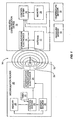
- FIG. 1 illustrates a wireless communication device and communication system that may be used with the present invention.
- the wireless communication device 10 is capable of communicating information wirelessly and may include a control system 12, communication electronics 14, and memory 16.
- the wireless communication device 10 may also be known as a radio-frequency identification device (RFID).
- RFID radio-frequency identification device
- the communication electronics 14 is coupled to an antenna 17 for wirelessly communicating information in radio-frequency signals.
- the communication electronics 14 is capable of receiving modulated radio-frequency signals through the antenna 17 and demodulating these signals into information passed to the control system 12.
- the antenna 17 may be any type of antenna, including but not limited to a pole or slot antenna.
- the antenna 17 may be internal or external to the wireless communication device 10.
- the control system 12 may be any type of circuitry or processor that receives and processes information received by the communication electronics 14, including a microcontroller or microprocessor.
- the wireless communication device 10 may also contain a memory 16 for storage of information. Such information may be any type of information about goods, objects, or articles of manufacture, including but not limited to identification, tracking, environmental information, such as pressure and temperature, and other pertinent information.
- the memory 16 may be electronic memory, such as random access memory (RAM), read-only memory (ROM), flash memory, diode, etc., or the memory 16 may be mechanical memory, such as a switch, dipswitch, etc.
- the control system 12 may also be coupled to sensors that sense environmental information concerning the wireless communication device 10.
- the control system 12 may be coupled to a pressure sensor 18 to sense the pressure on the wireless communication device 10 and/or its surroundings.
- the control system 12 may also be coupled to a temperature sensor 19 to sense the temperature of the wireless communication device 10 or the ambient temperature around the wireless communication device 10. More information on different types of pressure sensors 18 that can be used to couple to the control system are disclosed in U.S. Patent Nos. 6,299,349 and 6,272,936 , entitled “Pressure and temperature sensor” and “Pressure sensor,” respectively, both of which are incorporated herein by reference in their entirety.
- the temperature sensor 19 may be contained within the wireless communication device 10, or external to the wireless communication device 10.
- the temperature sensor 19 may be any variety of temperature sensing elements, such as a thermistor or chemical device.
- One such temperature sensor 19 is described in U.S. Patent No. 5,959,524 , entitled “Temperature sensor,” incorporated herein by reference in its entirety.
- the temperature sensor 19 may also be incorporated into the wireless communication device 10 or its control system 12, like that described in U.S. Patent No. 5,961,215 , entitled “Temperature sensor integral with microprocessor and methods of using same,” incorporated herein by reference in its entirety.
- the present invention is not limited to any particular type of temperature sensor 19.
- Some wireless communication devices 10 are termed “active” devices in that they receive and transmit data using their own energy source coupled to the wireless communication device 10.
- a wireless communication device 10 may use a battery for power as described in U.S. Patent No. 6,130,602 entitled “Radio frequency data communications device,” or may use other forms of energy, such as a capacitor as described in U.S. Patent No. 5,833,603 , entitled “Implantable biosensing transponder.” Both of the preceding patents are incorporated herein by reference in their entirety.
- wireless communication devices 10 are termed “passive” devices meaning that they do not actively transmit and therefore may not include their own energy source for power.
- One type of passive wireless communication device 10 is known as a "transponder.”
- a transponder effectively transmits information by reflecting back a received signal from an external communication device, such as an interrogation reader.
- An example of a transponder is disclosed in U.S. Patent No. 5,347,280 , entitled “Frequency diversity transponder arrangement,” incorporated herein by reference in its entirety.
- Another example of a transponder is described in co-pending U.S. Patent No. 6,501,435 , entitled “Wireless communication device and method,” incorporated herein by reference in its entirety.
- FIG. 1 depicts communication between a wireless communication device 10 and an interrogation reader 20.
- the interrogation reader 20 may include a control system 22, an interrogation communication electronics 24, memory 2 6, and an interrogation antenna 28.
- the interrogation antenna 28 may be any type of antenna, including a pole antenna or a slot antenna.
- the interrogation reader 20 may also contain its own internal energy source 30, or the interrogation reader 20 may be powered through an external power source.
- the energy source 30 may include batteries, a capacitor, solar cell or other medium that contains energy.
- the energy source 30 may also be rechargeable.
- a timer 23 may also be coupled to the control system 22 for performing tasks that require timing operations.
- the interrogation reader 20 communicates with the wireless communication device 10 by emitting an electronic signal 32 modulated by the interrogation communication electronics 24 through the interrogation antenna 28.
- the interrogation antenna 28 may be any type of antenna that can radiate a signal 32 through a field 34 so that a reception device, such as a wireless communication device 10, can receive such signal 32 through its own antenna 17.
- the field 34 may be electro-magnetic, magnetic, or electric.
- the signal 32 may be a message containing information and/or a specific request for the wireless communication device 10 to perform a task or communicate back information.
- the communication electronics 14 are energized by the energy in the signal 32, thereby energizing the wireless communication device 10.
- the wireless communication device 10 remains energized so long as its antenna 17 is in the field 34 of the interrogation reader 20.
- the communication electronics 14 demodulates the signal 32 and sends the message containing information and/or request to the control system 12 for appropriate actions.
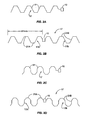
- Figure 2A illustrates a first embodiment of a wave antenna 17 coupled to a wireless communication device 10 for wireless communication.
- This embodiment illustrates a monopole hexagonal-shaped wave antenna 17.
- a hexagonal-shaped wave antenna 17 is one form of a polygonal-shaped wave antenna.
- a polygonal-shaped wave antenna is a plane figure with a number of sides should the antenna not reverse its direction to form a repeating pattern. In a regular polygon all the sides and internal angles are equal. For such a polygon with n sides, the interior angle is (180 - 360/ n ) degrees and the sum of the interior angles is (180 n - 360) degrees.
- the polygonal shapes described may be normal or not normal.
- polygonal-shapes are a square, a pentagon, a hexagon, a heptagon, an octagon, a nonagon, and a decagon, which are 4, 5, 6, 7, 8, 9 and 10-sided shapes respectively.
- the polygonal-shaped wave antennas are open such that approximately one half of the figure is above the x-axis center line of the antenna 17, and the other half is included below the x-axis center line of the antenna 17 so that the shape repeats in opposing fashion so that the antenna is not shorted. If the lower and upper portions of the wave antenna were superimposed on each other, a polygonal-shape figure would result.
- the hexagonal-shaped wave antenna 17 is formed by a conducting material, such as a wire or foil for example, that is in the shape of a hexagon.
- the hexagonal-shaped sections form a series of peaks and valleys in the conductor. Any type of material can be used to form the hexagonal-shaped wave antenna 17 so long as the material can conduct electrical energy, including but not limited to copper, brass, steel, zinc-plated steel, spring brass, and brass coated spring steel.
- the monopole hexagonal-shaped wave antenna 17 illustrated in Figure 2A is coupled, by either a direct or reactive coupling, to an input port (not shown) on the wireless communication device 10 to provide an antenna 17 for wireless communications. Since the wireless communication device 10 contains another input port that is coupled to the monopole hexagonal-shaped wave antenna 17, this additional input port is grounded.
- a wave antenna 17 may be particularly advantageous to use with a wireless communication device 10 in lieu of a straight antenna.
- One advantage of a wave antenna 17 is that it is tolerant to stretching without substantial risk of damage or breakage to the conductor. Certain types of goods, objects, or articles of manufacture may encounter a force, such as stretching or compression, during their manufacture and/or normal use. If a wireless communication device 10 uses a straight conductor as antenna 17 and is attached to goods, objects, or articles of manufacture that are subjected to a force during their manufacture or use, the antenna 17 may be damaged or broken when the good, object or article of manufacture is subjected to such force. If the antenna 17 is damaged or broken, this may cause the wireless communication device 10 to be incapable of wireless communication since a change in the length or shape of the conductor in the antenna 17 may change the operating frequency of the antenna 17.
- the impedance of a straight conductor antenna 17 is dependant on the type, size, and shape of the conductor.
- the length of the antenna 17 is the primary variable that determines the operating frequency of the antenna 17.
- a wave antenna 17 can be varied in other ways not possible in a straight conductor antenna. In a wave antenna 17, other variables exist in the design of the antenna in addition to the type, size, shape and length of the conductor.
- the impedance of a wave antenna 17 can also be varied by varying the length of the individual sections 21 of the conductor making up the wave antenna 17, the angle between these individual sections 21, and the phase, period, and amplitude of the sections 21, in addition to the traditional variables available in straight conductor antennas.
- a wave antenna 17 provides the ability to alter and select additional variables not possible in straight conductor antennas 17 that affect the impedance of the antenna 17, thereby creating a greater likelihood that the wave antenna's 17 impedance can be designed to more closely match the impedance of the wireless communication device 10.
- the type of materials attached to the wave antenna 17 and the materials' dielectric properties also vary the impedance and operating frequency of the wave antenna 17.
- These additional variables should also be taken into account in the final design of the wave antenna 17.
- the reactive cross-coupling that occurs between different sections 21 of the wave antenna 17 also contribute to greater impedance matching capability of the wave antenna 17 to a wireless communication device 10. More information on impedance matching between a wireless communication device 10 and an antenna 17 for efficient transfer of energy is disclosed in International Patent Application No. WO 01/73675 , entitled "Remote communication using slot antenna,” incorporated herein by reference in its entirety.
- Figure 2B illustrates a hexagonal-shaped wave antenna 17 similar to that illustrated in Figure 2A ; however, the hexagonal-shaped wave antenna in Figure 2B is a dipole hexagonal-shaped wave antenna 17.
- Two conductors 17A, 17B are coupled to the wireless communication device 10 to provide wireless communications.
- the length of the conductors 17A, 17B that form the dipole hexagonal-shaped wave antenna 17 are each 84 millimeters in length.
- the dipole hexagonal-shaped wave antenna 17 operates at a frequency of 915 MHz.
- the lengths of the individual sections 21 and the angles between the individual sections 21 that make up the dipole hexagonal-shaped wave antenna 17 are the same; however, they do not have to be.
- Figure 2C illustrates an alternative embodiment of Figure 2A , except that the wave antenna 17 comprises octagonal-shaped sections 21 . All other aspects of the octagonal-shaped wave antenna 17 embodiment discussed above and illustrated in Figure 2A are equally applicable for this embodiment
- Figure 2D illustrates an alternative embodiment of Figure 2B , except that the wave antenna 17 is comprised of sections 21 that are octagonal-shaped. All other aspects of the hexagonal-shaped wave antenna 17 embodiment discussed above and illustrated in Figure 2B are equally applicable for this embodiment.
- Figure 2E illustrates an alternative embodiment of Figure 2A , except that the wave antenna 17 comprises pentagonal-shaped sections 21. All other aspects for the pentagonal-shaped wave antenna 17 embodiment discussed above and illustrated in Figure 2A are equally applicable for this embodiment.
- Figure 2F illustrates an alternative embodiment of Figure 2B , except that the wave antenna 17 is comprised of sections 21 that are pentagonal-shaped. All other aspects for the pentagonal-shaped wave antenna 17 embodiment discussed above and illustrated in Figure 2B are equally applicable for this embodiment.
- Figure 2G illustrates an alternative embodiment of Figure 2A , except that the wave antenna 17 comprises square-shaped sections 21. All other aspects for the square-shaped wave antenna 17 embodiment discussed above and illustrated in Figure 2A are equally applicable for this embodiment.
- Figure 2H illustrates an alternative embodiment of Figure 2B , except that the wave antenna 17 is comprised of sections 21 that are square-shaped. All other aspects for the square-shaped wave antenna 17 embodiment discussed above and illustrated in Figure 2B are equally applicable for this embodiment.
- Figure 2I illustrates an alternative embodiment of Figure 2A , except that the wave antenna 17 comprises elliptical-curved sections 21.
- the wave antenna 17 is comprised of a series of alternating elliptical curves.
- the elliptical curves reverse in direction in an alternating and periodic pattern.
- the elliptical curves may be irregular curves meaning that they are uniform in angle.
- Figure 2J illustrates an alternative embodiment of Figure 2I , except that the wave antenna 17 is a dipole antenna. All other aspects for the elliptical curvo-shaped wave antenna 17 embodiment discussed above and illustrated in Figure 2I are equally applicable for this embodiment.
- Figure 2K illustrates an alternative embodiment of Figure 2A , except that the wave antenna 17 comprises coil-shaped sections 21.
- the coil shape is a series of curves in the wave antenna 17 that form a commonly known coil shape.
- An example of a coil shape is a spring.
- the coil-shaped wave antenna 17 may be constructed so that no two different sections 21 of the antenna 17 touch each other to prevent shorting even in normal contraction situations. Or the coil-shaped wave antenna 17 may be designed so that different section 21 short together under normal conditions and/or contraction depending on the operating characteristics desired.
- Figure 2L illustrates an alternative embodiment of Figure 2K , except that the wave antenna 17 is a dipole antenna. All other aspects for the elliptical curve-shaped wave antenna 17 embodiment discussed above and illustrated in Figure 2I are equally applicable for this embodiment.
- Figure 3A illustrates another embodiment of a hexagonal-shaped wave antenna 17 where the lengths of the individual sections 21 and the angle between the individual sections 21 are not the same.
- the hexagonal-shape of the wave antenna 17 is the same shape as illustrated and described in Figures 2A and 2B above.
- the first conductor is comprised out of two sections 21A, 21C, each having a different number of sections 21 and lengths.
- the two sections 21A, 21C are also symmetrically contained in the second conductor 21B, 21D. This causes the hexagonal-shaped wave antenna 17 to act as a dipole antenna that resonates and receives signals at two different operating frequencies so that the wireless communication device 10 is capable of communicating at two different frequencies.
- the first symmetrical sections 21A, 21B are 30.6 millimeters or ⁇ /4 in length and are coupled to the wireless communication device 10 so that the hexagonal-shaped wave antenna 17 is capable of receiving 2.45 GHz signals.
- the second symmetrical sections 21C, 21D are coupled to the first sections 21A, 21B, respectively, to form a second dipole antenna for receiving signals at a second frequency.
- the second sections 21C, 21D are 70 millimeters in length and are coupled to the first sections 21A, 21B, respectively, to form lengths that are designed to receive 915 MHz signals. Also note that bends in the conductor in the hexagonal-shaped wave antenna 17 are not constant.
- Figure 3B illustrates another embodiment similar to Figure 3A , except that the wave antenna 17 is octagonal-shaped.
- the octagonal-shape of the wave antenna 17 is the same shape as illustrated and described in Figures 2C and 2D above. All other aspects for the hexagonal-shaped wave antenna 17 embodiment discussed above and illustrated in Figure 3A are equally applicable for this embodiment.
- Figure 3C illustrates another embodiment similar to Figure 3A , except that the wave antenna 17 is pentagonal-shaped.
- the pentagonal-shape of the wave antenna 17 is the same shape as illustrated and described in Figures 2E and 2F above. All other aspects for the hexagonal-shaped wave antenna 17 embodiment discussed above and illustrated in Figure 3A are equally applicable for this embodiment.
- Figure 3D illustrates another embodiment similar to Figure 3A , except that the wave antenna 17 is square-shaped.
- the square-shape of the wave antenna 17 is the same shape as illustrated and described in Figures 2G and 2H above. All other aspects for the hexagonal-shaped wave antenna 17 embodiment discussed above and illustrated in Figure 3A are equally applicable for this embodiment.
- Figure 3E illustrates another embodiment similar to Figure 3A , except that the wave antenna 17 is elliptical curve-shaped.
- the elliptical curve-shape of the wave antenna 17 is the same shape as illustrated and described in Figures 2I and 2J above. All other aspects for the hexagonal-shaped wave antenna 17 embodiment discussed above and illustrated in Figure 3A are equally applicable for this embodiment.
- Figure 3F illustrates another embodiment similar to Figure 3A , except that the wave antenna 17 is coil-shaped.
- the coil-shape of the wave antenna 17 is the same shape as illustrated and described in Figures 2K and 2L above. All other aspects for the hexagonal-shaped wave antenna 17 embodiment discussed above and illustrated in Figure 3A are equally applicable for this embodiment.
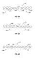
- Figure 4A illustrates another embodiment of a hexagonal-shaped wave antenna 17 where the amplitudes of the individual sections 21 that form the hexagonal-shaped wave antenna 17 are not the same.
- the hexagonal-shape of the wave antenna 17 is the same shape as illustrated and described in Figures 2A and 2B above.
- the first conductor is comprised out of two sections 21A, 21C, each having a different number of sections 21 and different amplitudes.
- the two sections 21A, 21C are also symmetrically contained in the second conductor 21B, 21D. This causes the hexagonal-shaped wave antenna 17 to act as a dipole antenna that resonates and receives signals at two different operating frequencies so that the wireless communication device 10 is capable of communicating at two different frequencies.
- Figure 4B illustrates another embodiment of an asymmetrical hexagonal-shaped wave antenna 17 where the amplitude of a first pole antenna 17A of the hexagonal-shaped wave antenna 17 has a different amplitude than the second pole antenna 17B of the hexagonal-shaped wave antenna 17. More information on asymmetrical pole antennas is disclosed in U.S.Patent No.6,501,435 , entitled “Wireless Communication Device and Method,” assigned to the same assignee as the present invention, and incorporated herein by reference in its entirety.
- Figure 4C illustrates another embodiment of an asymmetrical hexagonal-shaped wave antenna 17,where the length of a first pole antenna 17A of the hexagonal-shaped wave antenna 17 is of a different length than the second pole antenna 17B of the hexagonal-shaped wave antenna 17.
- Figures 4A, 4B, and 4C may be combined to create an asymmetrical hexagonal-shaped dipole wave antenna 17 wherein the pole antennas 17A, 17B contain different lengths and different amplitudes, including different amplitudes within different sections 21, of a pole antenna 17A, 17B.
- Figure 4D illustrates an alternative embodiment of Figure 4A , except that the wave antenna 17 is comprised of sections 21 that are octagonal-shaped like the wave antenna 17 illustrated in Figures 2C and 2D and described above. All other aspects for the hexagonal-shaped wave antenna 17 embodiment discussed above and illustrated in Figure 4A are equally applicable for this embodiment.
- Figure 4E illustrates an alternative embodiment of Figure 4B , except that the wave antenna 17 is comprised of sections 21 that are ociagonal-shaped like the wave antenna 17 illustrated in Figures 2C and 2D and described above. All other aspects for the hexagonal-shaped wave antenna 17 embodiment discussed above and illustrated in Figure 4B are equally applicable for this embodiment.
- Figure 4F illustrates an alternative embodiment of Figure 4C , except that the wave antenna 17 is comprised of sections 21 that are octagonal-circle shaped like the wave antenna 17 illustrated in Figures 2C and 2D and described above. All other aspects for the hexagonal-shaped wave antenna 17 embodiment discussed above and illustrated in Figure 4C are equally applicable for this embodiment.
- Figures 4D, 4E, and 4F may be combined to create an asymmetrical octagonal-shaped dipole wave antenna 17 wherein the pole antennas 17A, 17B contain different lengths and different amplitudes, including different amplitudes within different sections 21, of a pole antenna 17A, 17B.
- Figure 4G illustrates an alternative embodiment of Figure 4A , except that the wave antenna 17 is comprised of sections 21 that are pentagonal-shaped like the wave antenna 17 illustrated in Figures 2E and 2F and described above. All other aspects for the hexagonal-shaped wave antenna 17 embodiment discussed above and illustrated in Figure 4A are equally applicable for this embodiment.
- Figure 4H illustrates an alternative embodiment of Figure 4B , except that the wave antenna 17 is comprised of sections 21 that are pentagonal-shaped like the wave antenna 17 illustrated in Figures 2E and 2F and described above. All other aspects for the hexagonal-shaped wave antenna 17 embodiment discussed above and illustrated in Figure 4B are equally applicable for this embodiment.
- Figure 4I illustrates an alternative embodiment of Figure 4C , except that the wave antenna 17 is comprised of sections 21 that are pentagonal-shaped like the wave antenna 17 illustrated in Figures 2E and 2F and described above. All other aspects for the hexagonal-shaped wave antenna 17 embodiment discussed above and illustrated in Figure 4C are equally applicable for this embodiment.
- Figures 4G, 4H, and 4I may be combined to create an asymmetrical pentagonal-shaped dipole wave antenna 17 wherein the pole antennas 17A, 17B contain different lengths and different amplitudes, including different amplitudes within different sections 21, of a pole antenna 17A, 17B.
- Figure 4J illustrates an alternative embodiment of Figure 4A , except that the wave antenna 17 is comprised of sections 21 that are square-shaped like the wave antenna 17 illustrated in Figures 2G and 2H and described above. All other aspects for the hexagonal-shaped wave antenna 17 embodiment discussed above and illustrated in Figure 4A are equally applicable for this embodiment.
- Figure 4K illustrates an alternative embodiment of Figure 4B , except that the wave antenna 17 is comprised of sections 21 that are square-shaped like the wave antenna 17 illustrated in Figures 2G and 2H and described above. All other aspects for the hexagonal-shaped wave antenna 17 embodiment discussed above and illustrated in Figure 4B are equally applicable for this embodiment.
- Figure 4L illustrates an alternative embodiment of Figure 4C , except that the wave antenna 17 is comprised of sections 21 that are square-shaped like the wave antenna 17 illustrated in Figures 2G and 2H and described above. All other aspects for the hexagonal-shaped wave antenna 17 embodiment discussed above and illustrated in Figure 4C are equally applicable for this embodiment
- Figures 4J, 4K, and 4L may be combined to create an asymmetrical square-shaped dipole wave antenna 17 wherein the pole antennas 17A, 17B contain different lengths and different amplitudes, including different amplitudes within different sections 21, of a pole antenna 17A, 17B.
- Figure 4M illustrates an alternative embodiment of Figure 4A , except that the wave antenna 17 is comprised of sections 21 that are elliptical curve-shaped like the wave antenna 17 illustrated in Figures 2I and 2J and described above. All other aspects for the hexagonal-shaped wave antenna 17 embodiment discussed above and illustrated in Figure 4A are equally applicable for this embodiment.
- Figure 4N illustrates an alternative embodiment of Figure 4B , except that the wave antenna 17 is comprised of sections 21 that are elliptical curve-shaped like the wave antenna 17 illustrated in Figures 2I and 2J and described above. All other aspects for the hexagonal-shaped wave antenna 17 embodiment discussed above and illustrated in Figure 4B are equally applicable for this embodiment.
- Figure 4O illustrates an alternative embodiment of Figure 4C , except that the wave antenna 17 is comprised of sections 21 that are elliptical curve-shaped like the wave antenna 17 illustrated in Figures 2I and 2J and described above. All other aspects for the hexagonal-shaped wave antenna 17 embodiment discussed above and illustrated in Figure 4C are equally applicable for this embodiment.
- Figures 4M, 4N, and 4O may be combined to create an asymmetrical elliptical curve-shaped dipole wave antenna 17 wherein the pole antennas 17A, 17B contain different lengths and different amplitudes, including different amplitudes within different sections 21, of a pole antenna 17A, 17B.
- Figure 4P illustrates an alternative embodiment of Figure 4A , except that the wave antenna 17 is comprised of sections 21 that are coil-shaped like the wave antenna 17 illustrated in Figures 2K and 2L and described above. All other aspects for the hexagonal-shaped wave antenna 17 embodiment discussed above and illustrated in Figure 4A are equally applicable for this embodiment.
- Figure 4Q illustrates an alternative embodiment of Figure 4B , except that the wave antenna 17 is comprised of sections 21 that are coil-shaped like the wave antenna 17 illustrated in Figures 2K and 2L and described above. All other aspects for the hexagonal-shaped wave antenna 17 embodiment discussed above and illustrated in Figure 4B are equally applicable for this embodiment.
- Figure 4R illustrates an alternative embodiment of Figure 4C , except that the wave antenna 17 is comprised of sections 21 that are coil-shaped like the wave antenna 17 illustrated in Figures 2K and 2L and described above. All other aspects for the hexagonal-shaped wave antenna 17 embodiment discussed above and illustrated in Figure 4C are equally applicable for this embodiment.
- Figures 4P, 4Q, and 4R may be combined to create an asymmetrical coil-shaped dipole wave antenna 17 wherein the pole antennas 17A, 17B contain different lengths and different amplitudes, including different amplitudes within different sections 21, of a pole antenna 17A, 17B.
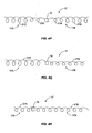
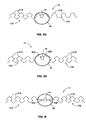
- FIG 5A illustrates another embodiment of the hexagonal-shaped wave antenna 17 coupled to the wireless communication device 10 wherein the wireless communication device 10 is configured to receive signals at two different frequencies.
- a hexagonal-shaped wave antenna 17 similar the hexagonal-shaped wave antenna 17 illustrated in Figures 2A and 2B is coupled to the wireless communication device 10 to form a dipole hexagonal-shaped wave antenna 17.
- a resonating ring 40 is also capacitively coupled to the wireless communication device 10 to provide a second antenna 17 that operates at a second and different frequency from the operating frequency of the dipole hexagonal-shaped wave antenna 17.
- the resonating ring 40 may be constructed out of any type of material so long as the material is conductive.
- This embodiment may be particularly advantageous if it is necessary for the wireless communication device 10 to be capable of wirelessly communicating regardless of the force, such as stretching or compression, exerted on the hexagonal-shaped wave antenna 17.
- the resonating ring 40 is designed to remain in its original shape regardless of the application of any force that may be placed on the wireless communication device 10 or a good, object, or article of manufacture that contains the wireless communication device 10.
- the length of the hexagonal-shaped wave antenna 17 may change, thereby changing the operating frequency of the hexagonal-shaped wave antenna 17.
- the new operating frequency of the hexagonal-shaped wave antenna 17 may be sufficiently different from the normal operating frequency such that hexagonal-shaped wave antenna 17 and the wireless communication device 10 could not receive and/or demodulate signals sent by the interrogation reader 20.
- the resonating ring 40 is capable of receiving signals 32 regardless of the state of the hexagonal-shaped wave antenna 17.
- Figure 5B also illustrates an embodiment of the present invention employing a dipole hexagonal-shaped wave antenna 17 that operates at 915 MHz and a resonating ring 40 that operates at 2.45GHz.
- the dipole hexagonal-shaped wave antenna 17 and the resonating ring 40 are both coupled to the wireless communication device 10 to allow the wireless communication device 10 to operate at two different frequencies.
- the conductors of the dipole hexagonal-shaped wave antenna 17 are looped around the resonating ring 40 at a first inductive turn 42A and a second inductive turn 42B. In this manner, any force placed on the dipole hexagonal-shaped wave antenna 17 will place such force on the resonating ring 40 instead of the wireless communication device 10.
- This embodiment may be advantageous in cases where a force placed on the dipole hexagonal-shaped wave antenna 17 without providing a relief mechanism other than the wireless communication device 10 itself would possibly cause the dipole hexagonal-shaped wave antenna 17 to disconnect from the wireless communication device 10, thus causing the wireless communication device 10 to be unable to wirelessly communicate.
- the resonating ring 40 may be constructed out of a stronger material than the connecting point between the dipole hexagonal-shaped wave antenna 17 and the wireless communication device 10, thereby providing the ability to absorb any force placed on the dipole hexagonal-shaped wave antenna 17 without damaging the resonating ring 40.
- This embodiment may also be particularly advantageous if the wireless communication device 10 is placed on a good, object or article of manufacture that undergoes force during its manufacture or use, such as a rubber tyre, for example.
- Figure 5C illustrates another embodiment similar to those illustrated in Figures 5A and 5B .
- the resonating ring 40 is directly coupled to the wireless communication device 10
- the dipole hexagonal-shaped wave antenna 17 is directly coupled to the resonating ring 10.
- a first and second conducting attachments 44A, 44B are used to couple the resonating ring 40 to the wireless communication device 10.
- a force exerted on the dipole hexagonal-shaped wave antenna 17 is exerted on and absorbed by the resonating ring 40 rather than wireless communication device 10 so that the wireless communication device 10 is not damaged.
- Figure 5D illustrates an alternative embodiment of Figure 5A , except that the wave antenna 17 is comprised of sections 21 that are octagonal-shaped like that illustrated in Figures 2C and 2D and described above. All other aspects for the hexagonal-shaped wave antenna 17 embodiment discussed above and illustrated in Figure 5A are equally applicable for this embodiment.
- Figure 5E illustrates an alternative embodiment of Figure 5B , except that the wave antenna 17 is comprised of sections 21 that are octagonal shaped like that illustrated in Figures 2C and 2D and described above. All other aspects for the hexagonal-shaped wave antenna 17 embodiment discussed above and illustrated in Figure 5B are equally applicable for this embodiment.
- Figure 5F illustrates an alternative embodiment of Figure 5C , except that the wave antenna 17 is comprised of sections 21 that are octagonal- shaped liked that illustrated in Figures 2C and 2D and described above. All other aspects for the hexagonal-shaped wave antenna 17 embodiment discussed above and illustrated in Figure 5C are equally applicable for this embodiment.
- Figure 5G illustrates an alternative embodiment of Figure 5A , except that the wave antenna 17 is comprised of sections 21 that are pentagonal-shaped like that illustrated in Figures 2E and 2F and described above. All other aspects for the hexagonal-shaped wave antenna 17 embodiment discussed above and illustrated in Figure 5A are equally applicable for this embodiment.
- Figure 5H illustrates an alternative embodiment of Figure 5B , except that the wave antenna 17 is comprised of sections 21 that are pentagonal-shaped that illustrated in Figures 2E and 2F and described above. All other aspects for the hexagonal-shaped wave antenna 17 embodiment discussed above and illustrated in Figure 5B are equally applicable for this embodiment.
- Figure 5I illustrates an alternative embodiment of Figure 5C , except that the wave antenna 17 is comprised of sections 21 that are pentagonal-shaped liked that illustrated in Figures 2E and 2F and described above. All other aspects for the hexagonal-shaped wave antenna 17 embodiment discussed above and illustrated in Figure 5C are equally applicable for this embodiment.
- Figure 5J illustrates an alternative embodiment of Figure 5A , except that the wave antenna 17 is comprised of sections 21 that are square-shaped like that illustrated in Figures 2G and 2H and described above. All other aspects for the hexagonal-shaped wave antenna 17 embodiment discussed above and illustrated in Figure 5A are equally applicable for this embodiment.
- Figure 5K illustrates an alternative embodiment of Figure 5B , except that the wave antenna 17 is comprised of sections 21 that are square-shaped that illustrated in Figures 2G and 2H and described above. All other aspects for the hexagonal-shaped wave antenna 17 embodiment discussed above and illustrated in Figure 5B are equally applicable for this embodiment.
- Figure 5L illustrates an alternative embodiment of Figure 5C , except that the wave antenna 17 is comprised of sections 21 that are square-shaped liked that illustrated in Figures 2G and 2H and described above. All other aspects for the hexagonal-shaped wave antenna 17 embodiment discussed above and illustrated in Figure 5C are equally applicable for this embodiment
- Figure 5M illustrates an alternative embodiment of Figure 5A , except that the wave antenna 17 is comprised of sections 21 that are elliptical curve-shaped like that illustrated in Figures 2I and 2J and described above. All other aspects for the hexagonal-shaped wave antenna 17 embodiment discussed above and illustrated in Figure 5A are equally applicable for this embodiment.
- Figure 5N illustrates an alternative embodiment of Figure 5B , except that the wave antenna 17 is comprised of sections 21 that are elliptical curve-shaped that illustrated in Figures 2I and 2J and described above. All other aspects for the hexagonal-shaped wave antenna 17 embodiment discussed above and illustrated in Figure 5B are equally applicable for this embodiment.
- Figure 5O illustrates an alternative embodiment of Figure 5C , except that the wave antenna 17 is comprised of sections 21 that are elliptical curve-shaped liked that illustrated in Figures 2I and 2J and described above. All other aspects for the hexagonal-shaped wave antenna 17 embodiment discussed above and illustrated in Figure 5C are equally applicable for this embodiment.
- Figure 5P illustrates an alternative embodiment of Figure 5A , except that the wave antenna 17 is comprised of sections 21 that are coil-shaped like that illustrated in Figures 2K and 2L and described above. All other aspects for the hexagonal-shaped wave antenna 17 embodiment discussed above and illustrated in Figure 5A are equally applicable for this embodiment.
- Figure 5Q illustrates an alternative embodiment of Figure 5B , except that the wave antenna 17 is comprised of sections 21 that are coil-shaped that illustrated in Figures 2K and 2L and described above. All other aspects for the hexagonal-shaped wave antenna 17 embodiment discussed above and illustrated in Figure 5B are equally applicable for this embodiment.
- Figure 5R illustrates an alternative embodiment of Figure 5C , except that the wave antenna 17 is comprised of sections 21 that are coil-shaped liked that illustrated in Figures 2K and 2L and described above. All other aspects for the hexagonal-shaped wave antenna 17 embodiment discussed above and illustrated in Figure 5C are equally applicable for this embodiment.
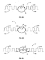
- Figure 6A illustrates another embodiment of the hexagonal-shaped wave antenna 17 like that illustrated in Figures 2A and 2B that illustrates sections 21 close to each other.
- the coupling between the individual elements in the hexagonal-shaped wave antenna 17 will be strong due to the proximity. Therefore, a small change in stretching of the hexagonal-shaped wave antenna 17 will have a large effect on the operating frequency of the hexagonal-shaped wave antenna 17. Since the change in the operating frequency will be great, it will be easier for a small stretching of the hexagonal-shaped wave antenna 17 to change the operating frequency of the hexagonal-shaped wave antenna 17.
- FIG 6B illustrates the same hexagonal-shaped wave antenna 17 and wireless communication device 10 illustrated in Figure 6A ; however, the hexagonal-shaped wave antenna 17 is not being stretched.
- the sections 21 in the hexagonal-shaped wave antenna 17 touch each other to effectively act as a regular dipole antenna without angled sections 21.
- each pole 17A, 17B of the hexagonal-shaped wave antenna 17 in its normal form is 30.6 millimeters long and has an operating frequency of 2.45 GHz such that the wireless communication device 10 is capable of responding to a frequency of 2.45 GHz.
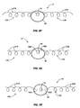
- Figure 6C illustrates an alternative embodiment of Figure 6A , except that the wave antenna 17 is comprised of sections 21 that are octagonal-shaped like that illustrated in Figures 2C and 2D . All other aspects for the hexagonal-shaped wave antenna 17 embodiment discussed above and illustrated in Figure 6A are equally applicable for this embodiment.
- Figure 6D illustrates an alternative embodiment of Figure 6B , except that the wave antenna 17 is comprised of sections 21 that are octagonal-shaped like that illustrated in Figures 2C and 2D . All other aspects for the hexagonal-shaped wave antenna 17 embodiment discussed above and illustrated in Figure 6B are equally applicable for this embodiment.
- Figure 6E illustrates an alternative embodiment of Figure 6A , except that the wave antenna 17-is comprised of sections 21 that are pentagonal-shaped like that illustrated in Figures 2E and 2F . All other aspects for the hexagonal-shaped wave antenna 17 embodiment discussed above and illustrated in Figure 6A are equally applicable for this embodiment.
- Figure 6F illustrates an alternative embodiment of Figure 6B , except that the wave antenna 17 is comprised of sections 21 that are pentagonal-shaped like that illustrated in Figures 2E and 2F . All other aspects for the hexagonal-shaped wave antenna 17 embodiment discussed above and illustrated in Figure 6B are equally applicable for this embodiment.
- Figure 6G illustrates an alternative embodiment of Figure 6A , except that the wave antenna 17 is comprised of sections 21 that are square-shaped like that illustrated in Figures 2G and 2H . All other aspects for the square-shaped wave antenna 17 embodiment discussed above and illustrated in Figure 6A are equally applicable for this embodiment.
- Figure 6H illustrates an alternative embodiment of Figure 6B , except that the wave antenna 17 is comprised of sections 21 that are square-shaped like that illustrated in Figures 2G and 2H . All other aspects for the hexagonal-shaped wave antenna 17 embodiment discussed above and illustrated in Figure 6B are equally applicable for this embodiment.
- Figure 6I illustrates an alternative embodiment of Figure 6A , except that the wave antenna 17 is comprised of sections 21 that are elliptical curve-shaped like that illustrated in Figures 2I and 2J . All other aspects for the square-shaped wave antenna 17 embodiment discussed above and illustrated in Figure 6A are equally applicable for this embodiment.
- Figure 6J illustrates an alternative embodiment of Figure 6B , except that the wave antenna 17 is comprised of sections 21 that are elliptical curve-shaped like that illustrated in Figures 2I and 2J . All other aspects for the hexagonal-shaped wave antenna 17 embodiment discussed above and illustrated in Figure 6B are equally applicable for this embodiment.
- Figure 6K illustrates an alternative embodiment of Figure 6A , except that the wave antenna 17 is comprised of sections 21 that are coil-shaped like that illustrated in Figures 2K and 2L . All other aspects for the square-shaped wave antenna 17 embodiment discussed above and illustrated in Figure 6A are equally applicable for this embodiment.
- Figure 6L illustrates an alternative embodiment of Figure 6B , except that the wave antenna 17 is comprised of sections 21 that are coil-shaped like that illustrated in Figures 2K and 2L . All other aspects for the hexagonal-shaped wave antenna 17 embodiment discussed above and illustrated in Figure 6B are equally applicable for this embodiment.
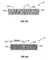
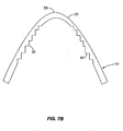
- Figure 7A illustrates an alternative embodiment of the conductive section 21 of the wave antenna 17 wherein the width of the section 21 is dynamically altered along the length of the shape of the section 21. This embodiment is useful for the polygonal-shaped wave antennas discussed above.
- Figure 7B illustrates an alternative embodiment of Figure 7A that is a conductive section 21 of the wave antenna 17 useful for a curve-shaped wave antenna 17, such as the elliptical-curve or coil shaped wave antennas 17 discussed above.
- This embodiment spreads the bending effect along the conductive section 21 so that the wave antenna 17 is less susceptible to breaking, just as the embodiment illustrated in Figure 7A .
- the discussion above related to Figure 7A is equally applicable for the embodiment illustrated in Figure 7B .
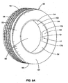
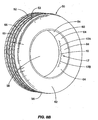
- Figure 8A illustrates one type of article of manufacture that undergoes force during its manufacture and use and that may include a wireless communication device 10 and wave antenna 17 like that illustrated in Figures 6A,-6L , or any of the previously discussed wave antennas 17.
- This embodiment includes a rubber tyre 50 well known in the prior art that is used on transportation vehicles.
- the tyre 50 is designed to be pressurized with air when mounted on a vehicle wheel forming a seal between the wheel and the tyre 50.
- the tyre 50 is comprised of a tread surface 52 that has a certain defined thickness 53.
- the tread surface 52 has a left outer side 54, a right outer side 56 and an orifice 58 in the center where the tyre 50 is designed to fit on a wheel.
- the left outer side 54 and right outer side 56 are curved downward at angles substantially perpendicular to the plane of the tread surface 52 to form a left outer wall 60 and a right outer wall 62.
- a left inner wall 64 and a right inner wall (not shown) on the inside of right outer wall 62 are also formed as well.
- a steel belt 68 may also be included inside the rubber of the tyre 50 under the surface of the tread surface 52 for increased performance and life. More information on the construction and design of a typical tyre 50 is disclosed in U.S. Patent No. 5,554,242 , entitled "Method for making a multi-component tyre," incorporated herein by reference in its entirety.
- a wireless communication device 10 and dipole wave antenna 17 are attached on the inner surface of the tyre 50 on the inner side of the tread surface 52.
- the rubber in the tyre 50 undergoes a lamination process whereby the tyre 50 may be stretched up to approximately 1.6 times its normal size and then shrunk back down to the normal dimensions of a wheel.
- the wireless communication device 10 and antenna 17 must be able to withstand the stretching and shrinking that a tyre 50 undergoes without being damaged.
- the wave antenna 17 of the present invention is particularly suited for this application since the wave antenna 17 can stretch and compress without damaging the conductor of the wave antenna 17.
- a tyre 50 is inflated with a gas, such as air, to a pressure during its normal operation. If the wireless communication device 10 and antenna 17 are placed inside the tread surface 52 or inside the tyre 50, the wireless communication device 10 and antenna 17 will stretch and compress depending on the pressure level in the tyre 50. The more pressure contained in the tyre 50, the more the tyre 50 will stretch. Therefore, any wireless communication device 10 and antenna 17 that is contained inside the tyre 50 or inside the rubber of the tyre 50 must be able to withstand this stretching without being damaged and/or affecting the proper operation of the wireless communication device 10.
- a gas such as air
- Figure 8B illustrates the same tyre illustrated in Figure 8A .
- the tyre 50 is under a pressure and has stretched the dipole wave antenna 17. Because the dipole wave antenna. 17 is capable of stretching without being damaged or broken, the dipole wave antenna 17 is not damaged and does not break when the tyre 50 is stretched when subjected to a pressure.
- the wave antenna 17 placed inside the tyre 50 could also be a monopole wave antenna 17, as illustrated in Figures 2A, 2C , 2E, 2G , 2I, and 2K or any other variation of the wave antenna 17, including the wave antennas 17 illustrated in Figures 2A-6L .
- the wireless communication device 10 and wave antenna 17 could be provided anywhere on the inside of the tyre 50, including inside the thickness 53 of the tread surface 52, the left inner wall 64 or the right inner wall (not shown) on the inside of right outer wall 62.
- the length of the wave antenna 17 for optimum coupling is affected by the electrical properties of the material surrounding, and in contact with, the conductive portions of the antenna 17. Since the rubber of the tyre 50 may contain large amounts of "carbon black," a relatively conductive material, an insulating material having the necessary electrical properties, may be required to encapsulate the metal of the antenna 17 with a non-conductive coating (not shown) to insulate it from the rubber of the tyre 50. In other cases the length of the antenna 17 elements must be tuned in length to match the electrical properties of the surrounding material, as is well known issue with antennas.
- wave antenna 17 discussed above and illustrated in Figures 8A and 8B may be any of the shapes discussed above and illustrated in Figures 2A-6L , including polygonal, elliptical curve and coil-shaped.
- Figure 9 illustrates a flowchart process wherein the interrogation reader 20 is designed to communicate with the wireless communication device 10 and wave antenna 17 to determine when the pressure of the tyre 50 has reached a certain designated threshold pressure. Because a wave antenna 17 changes length based on the force exerted on its conductors, a wave antenna 17 will stretch if placed inside a tyre 50 as the pressure inside the tyre 50 rises.
- the wave antenna 17 can be designed so that the length of the wave antenna 17 only reaches a certain designated length to be capable of receiving signals at the operating frequency of the interrogation reader 20 when the tyre 50 reaches a certain designated threshold pressure.
- the process starts (block 70), and the interrogation reader 20 emits a signal 32 through the field 34 as discussed previously for operation of the interrogation reader 20 and wireless communication device 10 illustrated in Figure 1 .
- the interrogation reader 20 checks to see if a response communication has been received from the wireless communication device 10 (decision 74). If no response signal is received by the interrogation reader 20 from the wireless communication device 10, the interrogation reader 20 continues to emit the signal 32 through field 34 in a looping fashion (block 72) until a response is received.
- the interrogation reader 20 can report that the tyre 50 containing the wireless communication device 10 and wave antenna 17 has reached a certain threshold pressure.
- the wave antennas 17 may be any of the wave antennas 17 illustrated in Figures 2A-6L .
- Figure 10 illustrates one embodiment of a reporting system 77 that may be provided for the interrogation reader 20.
- the interrogation reader 20 may be coupled to a reporting system 77.
- This reporting system 77 may be located in close proximity to the interrogation reader 20, and may be coupled to the interrogation reader 20 by either a wired or wireless connection.
- the reporting system 77 may be a user interface or other computer system that is capable of receiving and/or storing data communications received from an interrogation reader 20.
- This information may be any type of information received from a wireless communication device 10, including but not limited to identification information, tracking information, and/or environmental information concerning the wireless communication device 10 and/or its surroundings, such as pressure and temperature. The information may be used for any purpose.
- identification, tracking, temperature, force and/or pressure information concerning a tyre 50 during its manufacture may be communicated to the reporting system 77 which may then be used for tracking, quality control, and supply-chain management. If the information received by the reporting system is not normal or proper, the reporting system 77 may control the manufacturing operations to stop and/or change processes during manufacture and/or alert personnel in charge of the manufacturing process.
- the reporting system 77 may also communicate information received from the wireless communication device 10, via the interrogation reader 20, to a remote system 78 located remotely from the reporting system 77 and/or the interrogation reader 20.
- the communication between the reporting system 77 and the remote system 78 may be through wired communication, wireless communication, modem communication or other networking communication, such as the Internet.
- the interrogation reader 20 may communicate the information received from the wireless communication device 10 directly to the remote system 78 rather than first reporting the information through the reporting system 77 using the same or similar communication mediums as may be used between the reporting system 77 and the remote system 78.
- Figure 11 illustrates a method of manufacturing a wave antenna 17 and assembling of the wave antenna 17 to wireless communication devices 10 for any type of wave antenna 17 illustrated in Figure ZA-6L and discussed above.
- the process involves eight total steps. Each of the steps is labeled in circled numbers illustrated in Figure 11 .
- the first step of the process involves passing an antenna 17 conductor wire or foil through cogs 120 to create the alternating curves in the antenna conductor 17 to form the wave antenna 17.
- the cogs 120 are comprised of a top cog 120A and a bottom cog 120B.
- the top cog 120A rotates clockwise
- the bottom cog 120B rotates counterclockwise.
- Each cog 120A, 120B has a periphery such that each of the cogs 120A, 120B interlock with each other as they rotate.
- the cogs 120A, 120B are shaped to create the desired wave antenna 17 shape. As the antenna conductor 17 passes through the cogs 120A, 120B, alternating curves are placed in the antenna conductor 17 to form peaks 121 and valleys 122 in the antenna conductor 17 to form the wave antenna 17.
- the second step of the process involves placing tin solder on portions of the wave antenna 17 so that a wireless communication device 10 can be soldered and attached to the wave antenna 17 in a later step.
- a soldering station 123 is provided and is comprised of a first tinning position 123A and a second tinning position 123B.
- the first tinning position 123A and second tinning position 123B raise upward to place tin solder on the left side of the peak 124A and an adjacent right side of the peak 124B so that the wireless communication device 10 can be soldered to the wave antenna 17 in the third step of the process.
- the process may also use glue, induction welding, or other suitable adhesive, instead of solder, to attach the wireless communication device 10 to the wave antenna 17.
- the third step of the process involves attaching a wireless communication device 10 to the wave antenna 17.
- a wireless communication device is attached to the left side of the peak 124A and the right side of the peak 124B at the points of the tin solder.
- An adhesive 126 is used to attach the leads or pins (not shown) of the wireless communication device 10 to the tin solder, and solder paste is added to the points where the wireless communication device 10 attaches to the tin solder on the wave antenna 17 to conductively attach the wireless communication device 10 to the wave antenna 17. Note that when the wireless communication device 10 is attached to the wave antenna 17, the peak remains on the wireless communication device 10 that causes a short 128 between the two input ports (not shown) of the wireless communication device 10 and the two wave antennas 17 coupled to the wireless communication device 10.
- the fourth step in the process involves passing the wireless communication device 10 as connected to the wave antenna 17 through a hot gas re-flow soldering process well known to one of ordinary skill in the art to securely attach the solder between the leads of the wireless communication device 10 and the wave antenna 17.
- the fifth step in the process involves the well-lmown process of cleaning away any excess solder that is unused and left over during the previous soldering.
- the sixth step in the process involves removing the short 128 between the two wave antennas 17 left by the peak 124 of the wave antenna 17 from the third step in the process.
- the short 128 may or may not cause the wireless communication device 10 to not properly operate to receive signals and re-modulate response signals. If the wireless communication device 10 operation is not affected by this short 128, this step can be skipped in the process.
- the seventh step in the process involves encapsulating the wireless communication device 10.
- the wireless communication device 10 is typically in the form of an RF integrated circuit chip that is encapsulated within a hardened, non-conductive material, such as a plastic or epoxy, to protect the inside components of the chip from the environment.
- An additional encapsulating material, such as epoxy, may also be added over the bonding points of the wireless communication device 10 to the wave antenna 17 to add additional mechanical strain relief.
- the eighth and last step involves winding wireless communication devices 10 as attached on the wave antenna 17 onto a reel 130.
- the wireless communication devices 10 and wave antenna 17 are contained on a strip since the wave antenna 17 conductor has not been yet cut.
- the wireless communication device 10 and attached wave antenna 17 can be unwound from the reel 130 and the wave antenna 17 conductor cut in the middle between two consecutive wireless communication devices 10 to form separate wireless communication devices 10 and dipole wave antennas 17.
- the wave antenna 17 may be for any shaped wave antenna 17 previously discussed.
- Figure 12 illustrates the short 128 left on the wireless communication device 10 and polygonal-shaped wave antenna 17 as a tuning inductance.
- Some UHF wireless communication devices 10 operate best when a direct current (DC) short, in the form of a tuning inductance, is present across the wireless communication device 10 and, therefore, the process of removing the short 128 can be omitted.
- Figure 12A illustrates an alternative embodiment of the polygonal-shaped wave antenna 17 and wireless communication device 10 where an uneven cog 120 has been used in step 1 of the process illustrated in Figure 11 to produce an extended loop short 128 across the wireless communication device 10. This gives the required amount of inductance for best operation of the wireless communication device 10 as the wave antenna 17 and the short 128 are in parallel.
- the present invention is not limited to applications involving a vehicle tyre. It should also be understood that the present invention is not limited to any particular type of component, including but not limited to the wireless communication device 10 and its components, the wave antenna 17, the interrogation reader 20 and its components, the pressure sensor 18, the temperature sensor 19, the resonating ring 40, the tyre 50 and its components, the reporting system 77, the remote system 78, the wheel 100 and its components, the cogs 120, the soldering station 123, and the adhesive 124.
- couple, coupled, or coupling is defined as either a direct connection or a reactive coupling.
- Reactive coupling is defined as either capacitive or inductive coupling.
- the wave antenna 17 discussed in this application may be polygonal, elliptical-curve, or coil-shaped.
Landscapes
- Engineering & Computer Science (AREA)
- Theoretical Computer Science (AREA)
- Computer Hardware Design (AREA)
- Microelectronics & Electronic Packaging (AREA)
- Physics & Mathematics (AREA)
- General Physics & Mathematics (AREA)
- Mechanical Engineering (AREA)
- Computer Networks & Wireless Communication (AREA)
- Signal Processing (AREA)
- Details Of Aerials (AREA)
- Support Of Aerials (AREA)
- Arrangements For Transmission Of Measured Signals (AREA)
- Facsimile Transmission Control (AREA)
Abstract

Description
- This invention relates to wireless communication devices.
- Such wireless communications devices form the subject of prior International Patent Application No.
PCT/IB02/05095 - The present invention relates to a wave antenna coupled to a wireless communication device so that the wireless communication device can wirelessly communicate information.
- Wireless communication devices are commonly used today to wirelessly communicate information about goods. For example, transponders may be attached to goods during their manufacture, transport and/or distribution to provide information, such as the good's identification number, expiration date, date of manufacture or "born on" date, lot number, and the like. The transponder allows this information to be obtained unobtrusively using wireless communication without slowing down the manufacturing, transportation, and/or distribution process.
- Some goods involve environmental factors that are critical to their manufacture and/or intended operation. An example of such a good is a vehicle tyre. It may be desirable to place a wireless communication device in a tyre so that information regarding the tyre, such as a tyre's identification, pressure, temperature, and other environmental information, can be wirelessly communicated to an interrogation reader during the tyre's manufacture and/or use.
- Tyre pressure monitoring may be particularly important since the pressure in a tyre governs its proper operation and safety in use. For example, too little pressure in a tyre during its use can cause a tyre to be damaged by the weight of a vehicle supported by the tyre. Too much pressure can cause a tyre to rupture. Tyre pressure must be tested during the manufacturing process to ensure that the tyre meets intended design specifications. The tyre pressure should also be within a certain pressure limits during use in order to avoid dangerous conditions. Knowledge of the tyre pressure during the operation of a vehicle can be used to inform an operator and/or vehicle system that a tyre has a dangerous pressure condition. The vehicle may indicate a pressure condition by generating an alarm or warning signal to the operator of the vehicle.
- During the manufacturing process of a tyre, the rubber material comprising the vehicle tyre is violently stretched before taking final shape. Wireless communication devices placed inside tyres during their manufacture must be able to withstand this stretching and compression and still be able to operate properly after the completion of the tyre's manufacture. Since wireless communication devices are typically radio-frequency communication devices, an antenna must be coupled to the wireless communication device for communication. This antenna and wireless communication device combination may be placed in the inside of the tyre along its inner wall or inside the rubber of the tyre, for example. This results in stretching and compression of the wireless communication device and its antenna whenever the tyre is stretched and compressed. Often, the antenna is stretched and subsequently damaged or broken, thereby either disconnecting the wireless communication device from an antenna or changing the length of the antenna, which changes the operating frequency of the antenna. In either case, the wireless communication device may be unable to communicate properly when the antenna is damaged or broken. Therefore, an object of the present invention is to provide an antenna for a wireless communication device that can withstand a force, such as stretching or compression, and not be susceptible to damage or a break. In this manner, a high level of operability can be achieved with wireless communication devices coupled to antennas for applications where a force is placed on the antenna.
- The present invention relates to a wave antenna that is coupled to a wireless communication device, such as a transponder, to wirelessly communicate information. The wave antenna is a conductor. The wave antenna may be shaped in the form of various different types of curvatures, including a polygonal shape, elliptical curvature, and a coil. Polygonal shapes include curvatures having three or more sides.
- The wave antenna is capable of stretching when subjected to a force without being damaged. The wave antenna can also provide improved impedance matching capability between the antenna and a wireless communication device because of the reactive interaction between different sections of the antenna conductor. In general, varying the characteristics of the conductor wire of the wave antenna, such as diameter, the angle of the curves or bends, the lengths of the sections formed by the curves or bends, the period, phase, and/or amplitude of the conductor, and the type of conductor wire, will modify the cross coupling and, hence, the impedance of the wave antenna.
- In a first wave antenna embodiment, a wireless communication device is coupled to a single conductor wave antenna to form a monopole wave antenna. The wave antenna conductor may be shaped in the form of polygonal shape, elliptical curvature, or a coil.
- In a second wave antenna embodiment, a wireless communication device is coupled to two conductor wave antennas to form a dipole wave antenna. The wave antenna conductor may be shaped in the form of polygonal shape, elliptical curvature, or a coil.
- In a third wave antenna embodiment, a dipole wave antenna is comprised out of conductors having different sections having different lengths. The first section is coupled to the wireless communication device and forms a first antenna having a first operating frequency. The second section is coupled to the first section and forms a second antenna having a second operating frequency. The wireless communication device is capable of communicating at each of these two frequencies formed by the first antenna and the second antenna. The wave antenna conductor may be shaped in the form of polygonal shape, elliptical curvature, or a coil.
- In a fourth wave antenna embodiment, a dipole wave antenna is comprised out of conductive sections having different amplitudes. A first section, having a first amplitude, is coupled to the wireless communication device and forms a first antenna having a first operating frequency. The second section, having a second amplitude different from the amplitude of the first section, is coupled to the first section to form a second antenna having a second operating frequency. The wireless communication device is capable of communicating at each of these two frequencies formed by the first antenna and the second antenna. Each pole of the wave antenna is symmetrical. The wave antenna conductor may be shaped in the form of polygonal shape, elliptical curvature, or a coil.
- In a fifth wave antenna embodiment, an asymmetrical dipole wave antenna is comprised out of conductive sections having different amplitudes. A first conductor, having a first amplitude, is coupled to the wireless communication device to form one pole of the dipole wave antenna. The second conductor, having a second amplitude different from the amplitude of the first pole, is coupled to the wireless communication device to form the second pole of the dipole wave antenna. The wave antenna conductor may be shaped in the form of polygonal shape, elliptical curvature, or a coil.
- In a sixth wave antenna embodiment, an asymmetrical dipole wave antenna is comprised out of conductive sections having different lengths. A first conductor, having a first length, is coupled to the wireless communication device to form one pole of the dipole wave antenna. The second conductor, having a second length different from the length of the first pole, is coupled to the wireless communication device to form the second pole of the dipole wave antenna. The wave antenna conductor may be shaped in the form of polygonal shape, elliptical curvature, or a coil.
- In a seventh wave antenna embodiment, a resonating conductor is additionally coupled to the wireless communication device to provide a second antenna operating at a second operating frequency. The resonating ring may also act as a stress relief for force placed on the wave antenna so that such force is not placed on the wireless communication device. The wave antenna conductor may be shaped in the form of polygonal shape, elliptical curvature, or a coil.
- In another embodiment, the wireless communication device is coupled to a wave antenna and is placed inside a tyre so that information can be wirelessly communicated from the tyre to an interrogation reader. The wave antenna is capable of stretching and compressing, without being damaged, as the tyre is stretched and compressed during its manufacture and pressurization during use on a vehicle. The wave antenna conductor may be shaped in the form of polygonal shape, elliptical curvature, or a coil.
- In another embodiment, the interrogation reader determines the pressure inside a tyre by the response from a wireless communication device coupled to a wave antenna placed inside the tyre. When the tyre and, therefore, the wave antenna stretch to a certain length indicative that the tyre is at a certain threshold pressure, the length of the antenna will be at the operating frequency of the interrogation reader so that the wireless communication device is capable of responding to the interrogation reader. The wave antenna conductor may be shaped in the form of polygonal shape, elliptical curvature, or a coil.
- In another embodiment, a method of manufacture is disclosed on one method of manufacturing the wave antenna out of a straight conductor and attaching wireless communication devices to the wave antenna. The uncut string of wireless communication devices and wave antennas form one continuous strip that can be wound on a reel and later unwound, cut and applied to a good, object, or article of manufacture. The wave antenna conductor may be shaped in the form of polygonal shape, elliptical curvature, or a coil.
- Ways of carrying out the invention will now be described in detail, by way of example, with reference to the accompanying drawings, in which;
-
Figure 1 is a schematic diagram of an interrogation reader and wireless communication device system that may be used with the present invention; -
Figure 2A is a schematic diagram of a monopole hexagonal-shaped wave antenna coupled to a wireless communication device for wireless communications; -
Figure 2B is a schematic diagram of a dipole hexagonal-shaped wave antenna coupled to a wireless communication device for wireless communications; -
Figure 2C is a schematic diagram of a monopole octagonal-shaped wave antenna coupled to a wireless communication device for wireless communications; -
Figure 2D is a schematic diagram of a dipole octagonal-shaped wave antenna coupled to a wireless communication device for wireless communications; -
Figure 2E is a schematic diagram of a monopole pentagonal-shaped wave antenna coupled to a wireless communication device for wireless communications; -
Figure 2F is a schematic diagram of a dipole pentagonal-shaped wave antenna coupled to a wireless communication device for wireless communications; -
Figure 2G is a schematic diagram of a monopole square-shaped wave antenna coupled to a wireless communication device for wireless communications; -
Figure 2H is a schematic diagram of a dipole square-shaped wave antenna coupled to a wireless communication device for wireless communications; -
Figure 2I is a schematic diagram of a monopole elliptical curve-shaped wave antenna coupled to a wireless communication device for wireless communications; -
Figure 2J is a schematic diagram of a dipole elliptical curve-shaped wave antenna coupled to a wireless communication device for wireless communications; -
Figure 2K is a schematic diagram of a monopole coil-shaped wave antenna coupled to a wireless communication device for wireless communications; -
Figure 2L is a schematic diagram of a dipole coil-shaped wave antenna coupled to a wireless communication device for wireless communications; -
Figure 3A is a schematic diagram of a dipole hexagonal-shaped wave antenna coupled to a wireless communication device wherein a first portion of the hexagonal-shaped wave antenna operates at a first frequency and a second portion of the hexagonal-shaped wave antenna coupled to the first portion operates at a second frequency; -
Figure 3B is a schematic diagram of a dipole octagonal-shaped wave antenna coupled to a wireless communication device wherein a first portion of the octagonal-shaped wave antenna operates at a first frequency and a second portion of the octagonal-shaped wave antenna coupled to the first portion operates at a second frequency; -
Figure 3C is a schematic diagram of a dipole pentagonal-shaped wave antenna coupled to a wireless communication device wherein a first portion of the pentagonal-shaped wave antenna operates at a first frequency and a second portion of the pentagonal-shaped wave antenna coupled to the first portion operates at a second frequency; -
Figure 3D is a schematic diagram of a dipole square-shaped wave antenna coupled to a wireless communication device wherein a first portion of the square-shaped wave antenna operates at a first frequency and a second portion of the square-shaped wave antenna coupled to the first portion operates at a second frequency; -
Figure 3E is a schematic diagram of a dipole elliptical curve-shaped wave antenna coupled to a wireless communication device wherein a first portion of the elliptical curve-shaped wave antenna operates at a first frequency and a second portion of the elliptical curve-shaped wave antenna coupled to the first portion operates at a second frequency; -
Figure 3F is a schematic diagram of a dipole coil-shaped wave antenna coupled to a wireless communication device wherein a first portion of the coil-shaped wave antenna operates at a first frequency and a second portion of the coil-shaped wave antenna coupled to the first portion operates at a second frequency; -
Figure 4A is a schematic diagram of a dipole hexagonal-shaped wave antenna coupled to a wireless communication device for wireless communications wherein each hexagonal-shaped pole conductor comprises two sections each having different amplitudes; -
Figure 4B is a schematic diagram of a dipole hexagonal-shaped wave antenna coupled to a wireless communication device for wireless communications wherein one hexagonal-shaped pole conductor has an amplitude larger than the other hexagonal-shaped pole conductor; -
Figure 4C is a schematic diagram of a dipole hexagonal-shaped wave antenna coupled to a wireless communication device for wireless communications wherein one hexagonal-shaped pole conductor is longer than the other hexagonal-shaped pole conductor; -
Figure 4D is a schematic diagram of a dipole octagonal-shaped wave antenna coupled to a wireless communication device for wireless communications wherein each octagonal-shaped pole conductor comprises two sections each having different amplitudes; -
Figure 4E is a schematic diagram of a dipole octagonal-shaped wave antenna coupled to a wireless communication device for wireless communications wherein one octagonal-shaped pole conductor has an amplitude larger than the other octagonal-shaped pole conductor; -
Figure 4F is a schematic diagram of a dipole octagonal-shaped wave antenna coupled to a wireless communication device for wireless communications wherein one octagonal-shaped pole conductor is longer than the other octagonal-shaped pole conductor; -
Figure 4G is a schematic diagram of a dipole pentagonal-shaped wave antenna coupled to a wireless communication device for wireless communications wherein each pentagonal-shaped pole conductor comprises two sections each having different amplitudes; -
Figure 4H is a schematic diagram of a dipole pentagonal shaped wave antenna coupled to a wireless communication device for wireless communications wherein one pentagonal-shaped pole conductor has an amplitude larger than the other pentagonal-shaped pole conductor; -
Figure 4I is a schematic diagram of a dipole pentagonal-shaped wave antenna coupled to a wireless communication device for wireless communications wherein one pentagonal-shaped pole conductor is longer than the other pentagonal-shaped pole conductor; -
Figure 4J is a schematic diagram of a dipole square-shaped wave antenna coupled to a wireless communication device for wireless communications wherein each square-shaped pole conductor comprises two sections each having different amplitudes; -
Figure 4K is a schematic diagram of a dipole square-shaped wave antenna coupled to a wireless communication device for wireless communications wherein one square-shaped pole conductor has an amplitude larger than the other square-shaped pole conductor; -
Figure 4L is a schematic diagram of a dipole square-shaped wave antenna coupled to a wireless communication device for wireless communications wherein one square-shaped pole conductor is longer than the other square-shaped pole conductor; -
Figure 4M is a schematic diagram of a dipole elliptical curve-shaped wave antenna coupled to a wireless communication device for wireless communications wherein each elliptical curve-shaped pole conductor comprises two sections each having different amplitudes; -
Figure 4N is a schematic diagram of a dipole elliptical curve-shaped wave antenna coupled to a wireless communication device for wireless communications wherein one elliptical curve-shaped pole conductor has an amplitude larger than the other elliptical curve-shaped pole conductor; -
Figure 4O is a schematic diagram of a dipole elliptical curve-shaped wave antenna coupled to a wireless communication device for wireless communications wherein one elliptical curve-shaped pole conductor is longer than the other elliptical curve-shaped pole conductor; -
Figure 4P is a schematic diagram of a dipole coil-shaped wave antenna coupled to a wireless communication device for wireless communications wherein each coil-shaped pole conductor comprises two sections each having different amplitudes; -
Figure 4Q is a schematic diagram of a dipole coil-shaped wave antenna coupled to a wireless communication device for wireless communications wherein one coil-shaped pole conductor has an amplitude larger than the other coil-shaped pole conductor; -
Figure 4R is a schematic diagram of a dipole coil-shaped wave antenna coupled to a wireless communication device for wireless communications wherein one coil-shaped pole conductor is longer than the other coil-shaped pole conductor, -
Figure 5A is a schematic diagram of a hexagonal-shaped wave antenna and a ring resonator both coupled to a wireless communication device wherein the hexagonal-shaped wave antenna operates at a first frequency and the ring resonator operates at a second frequency; -
Figure 5B is a schematic diagram of the hexagonal-shaped wave antenna and a ring resonator as illustrated inFigure 5A , except that the ring resonator is additionally mechanically coupled to the hexagonal-shaped wave antenna as a mechanical stress relief; -
Figure 5C is a schematic diagram of an alternative embodiment toFigure 5B ; -
Figure 5D is a schematic diagram of a octagonal-shaped wave antenna and a ring resonator both coupled to a wireless communication device wherein the octagonal-shaped wave antenna operates at a first frequency and the ring resonator operates at a second frequency; -
Figure 5E is a schematic diagram of the octagonal-shaped wave antenna and a ring resonator as illustrated inFigure 5D , except that the ring resonator is additionally mechanically coupled to the octagonal-shaped wave antenna as a mechanical stress relief; -
Figure 5F is a schematic diagram of an alternative embodiment toFigure 5E ; -
Figure 5G is a schematic diagram of a pentagonal-shaped wave antenna and a ring resonator both coupled to a wireless communication device wherein the pentagonal-shaped wave antenna operates at a first frequency and the ring resonator operates at a second frequency; -
Figure 5H is a schematic diagram of the pentagonal-shaped wave antenna and a ring resonator as illustrated inFigure 5G , except that the ring resonator is additionally mechanically coupled to the pentagonal-shaped wave antenna as a mechanical stress relief; -
Figure 5I is a schematic diagram of an alternative embodiment toFigure 5H ; -
Figure 5J is a schematic diagram of a square-shaped wave antenna and a ring resonator both coupled to a wireless communication device wherein the square-shaped wave antenna operates at a first frequency and the ring resonator operates at a second frequency; -
Figure 5K is a schematic diagram of the square-shaped wave antenna and a ring resonator as illustrated inFigure 5J , except that the ring resonator is additionally mechanically coupled to the square-shaped wave antenna as a mechanical stress relief; -
Figure 5L is a schematic diagram of an alternative embodiment toFigure 5K ; -
Figure 5M is a schematic diagram of an elliptical curve-shaped wave antenna and a ring resonator both coupled to a wireless communication device wherein the elliptical curve-shaped wave antenna operates at a first frequency and the ring resonator operates at a second frequency; -
Figure 5N is a schematic diagram of the elliptical curve-shaped wave antenna and a ring resonator as illustrated inFigure 5M , except that the ring resonator is additionally mechanically coupled to the elliptical curve-shaped wave antenna as a mechanical stress relief; -
Figure 5O is a schematic diagram of an alternative embodiment toFigure 5N ; -
Figure 5P is a schematic diagram of a coil-shaped wave antenna and a ring resonator both coupled to a wireless communication device wherein the coil-shaped wave antenna operates at a first frequency and the ring resonator operates at a second frequency; -
Figure 5Q is a schematic diagram of the coil-shaped wave antenna and a ring resonator as illustrated inFigure 5P , except that the ring resonator is additionally mechanically coupled to the coil-shaped wave antenna as a mechanical stress relief; -
Figure 5R is a schematic diagram of an alternative embodiment toFigure 5Q ; -
Figure 6A is a schematic diagram of another embodiment of a hexagonal-shaped wave antenna and wireless communication device; -
Figure 6B is a schematic diagram of a compressed version of the hexagonal-shaped wave antenna illustrated inFigure 6A ; -
Figure 6C is a schematic diagram of another embodiment of an octagonal-shaped wave antenna and wireless communication device; -
Figure 6D is a schematic diagram of a compressed version of the octagonal-shaped wave antenna illustrated inFigure 6C ; -
Figure 6E is a schematic diagram of another embodiment of an pentagonal-shaped wave antenna and wireless communication device; -
Figure 6F is a schematic diagram of a compressed version of the pentagonal-shaped wave antenna illustrated inFigure 6E ; -
Figure 6G is a schematic diagram of another embodiment of an square-shaped wave antenna and wireless communication device; -
Figure 6H is a schematic diagram of a compressed version of the square-shaped wave antenna illustrated inFigure 6G ; -
Figure 6I is a schematic diagram of another embodiment of an elliptical curve-shaped wave antenna and wireless communication device; -
Figure 6J is a schematic diagram of a compressed version of the elliptical curve-shaped wave antenna illustrated inFigure 6I ; -
Figure 6K is a schematic diagram of another embodiment of an coil-shaped wave antenna and wireless communication device; -
Figure 6L is a schematic diagram of a compressed version of the coil-shaped wave antenna illustrated inFigure 6K ; -
Figure 7A is a schematic diagram of modifications to a curved section of the wave antenna to spread the bend angle of the conductive section over a larger linear length of the bend; -
Figure 7B is a schematic diagram of modifications to a section side of the wave antenna to spread the bend angle of the conductive section over a larger linear length of the bend; -
Figure 8A is a schematic diagram of a wireless communication device and wave antenna attached to the inside of a tyre for wireless communication of information about the tyre; -
Figure 8B is a schematic diagram of the wireless communication device and wave antenna ofFigure 8A , except that the tyre is under pressure and is stretching the wave antenna; -
Figure 9 is a flowchart diagram of a tyre pressure detection system executed by an interrogation reader by communicating with a wireless communication device coupled to a wave antenna inside a tyre like that illustrated inFigures 8A and8B ; -
Figure 10 is a schematic diagram of a reporting system for information wirelessly communicated from a tyre to an interrogation reader; -
Figure 11 is a schematic diagram of a process of manufacturing a wave antenna and coupling the wave antenna to a wireless communication device; and -
Figure 12 is a schematic diagram of an inductance tuning short provided by the manufacturing process illustrated inFigure 11 . - The present invention relates to a wave antenna that is coupled to a wireless communication device, such as a transponder, to wirelessly communicate information. The wave antenna may be a conductor shaped in the form of a polygonal shape, elliptical curvature, or a coil.
- A wave antenna has bends or curves that allow stretching or compressing of the conductor comprising the antenna without being damaged when subjected to a force.
- A wave antenna can also provide improved impedance matching capability between the antenna and a wireless communication device because of the reactive interaction between different sections of the antenna conductor. In general, varying the characteristics of the conductor wire of the wave antenna, such as the diameter, the angle of the bends or curves, the lengths of the sections formed by the bends or curves, and the type of conductor wire, will modify the cross coupling and, hence, the impedance of the wave antenna.
- Before discussing the particular aspects and applications of the wave antenna as illustrated in
Figures 2-12 of this application, a wireless communication system that may be used with the present invention is discussed below. -
Figure 1 illustrates a wireless communication device and communication system that may be used with the present invention. Thewireless communication device 10 is capable of communicating information wirelessly and may include acontrol system 12,communication electronics 14, andmemory 16. Thewireless communication device 10 may also be known as a radio-frequency identification device (RFID). Thecommunication electronics 14 is coupled to anantenna 17 for wirelessly communicating information in radio-frequency signals. Thecommunication electronics 14 is capable of receiving modulated radio-frequency signals through theantenna 17 and demodulating these signals into information passed to thecontrol system 12. Theantenna 17 may be any type of antenna, including but not limited to a pole or slot antenna. Theantenna 17 may be internal or external to thewireless communication device 10. - The
control system 12 may be any type of circuitry or processor that receives and processes information received by thecommunication electronics 14, including a microcontroller or microprocessor. Thewireless communication device 10 may also contain amemory 16 for storage of information. Such information may be any type of information about goods, objects, or articles of manufacture, including but not limited to identification, tracking, environmental information, such as pressure and temperature, and other pertinent information. Thememory 16 may be electronic memory, such as random access memory (RAM), read-only memory (ROM), flash memory, diode, etc., or thememory 16 may be mechanical memory, such as a switch, dipswitch, etc. - The
control system 12 may also be coupled to sensors that sense environmental information concerning thewireless communication device 10. For instance, thecontrol system 12 may be coupled to apressure sensor 18 to sense the pressure on thewireless communication device 10 and/or its surroundings. Thecontrol system 12 may also be coupled to atemperature sensor 19 to sense the temperature of thewireless communication device 10 or the ambient temperature around thewireless communication device 10. More information on different types ofpressure sensors 18 that can be used to couple to the control system are disclosed inU.S. Patent Nos. 6,299,349 and6,272,936 , entitled "Pressure and temperature sensor" and "Pressure sensor," respectively, both of which are incorporated herein by reference in their entirety. - The
temperature sensor 19 may be contained within thewireless communication device 10, or external to thewireless communication device 10. Thetemperature sensor 19 may be any variety of temperature sensing elements, such as a thermistor or chemical device. Onesuch temperature sensor 19 is described inU.S. Patent No. 5,959,524 , entitled "Temperature sensor," incorporated herein by reference in its entirety. Thetemperature sensor 19 may also be incorporated into thewireless communication device 10 or itscontrol system 12, like that described inU.S. Patent No. 5,961,215 , entitled "Temperature sensor integral with microprocessor and methods of using same," incorporated herein by reference in its entirety. However, note that the present invention is not limited to any particular type oftemperature sensor 19. - Some
wireless communication devices 10 are termed "active" devices in that they receive and transmit data using their own energy source coupled to thewireless communication device 10. Awireless communication device 10 may use a battery for power as described inU.S. Patent No. 6,130,602 entitled "Radio frequency data communications device," or may use other forms of energy, such as a capacitor as described inU.S. Patent No. 5,833,603 , entitled "Implantable biosensing transponder." Both of the preceding patents are incorporated herein by reference in their entirety. - Other
wireless communication devices 10 are termed "passive" devices meaning that they do not actively transmit and therefore may not include their own energy source for power. One type of passivewireless communication device 10 is known as a "transponder." A transponder effectively transmits information by reflecting back a received signal from an external communication device, such as an interrogation reader. An example of a transponder is disclosed inU.S. Patent No. 5,347,280 , entitled "Frequency diversity transponder arrangement," incorporated herein by reference in its entirety. Another example of a transponder is described in co-pendingU.S. Patent No. 6,501,435 , entitled "Wireless communication device and method," incorporated herein by reference in its entirety. -
Figure 1 depicts communication between awireless communication device 10 and aninterrogation reader 20. Theinterrogation reader 20 may include acontrol system 22, aninterrogation communication electronics 24,memory 2 6, and aninterrogation antenna 28. Theinterrogation antenna 28 may be any type of antenna, including a pole antenna or a slot antenna. Theinterrogation reader 20 may also contain its owninternal energy source 30, or theinterrogation reader 20 may be powered through an external power source. Theenergy source 30 may include batteries, a capacitor, solar cell or other medium that contains energy. Theenergy source 30 may also be rechargeable. Atimer 23 may also be coupled to thecontrol system 22 for performing tasks that require timing operations. - The
interrogation reader 20 communicates with thewireless communication device 10 by emitting anelectronic signal 32 modulated by theinterrogation communication electronics 24 through theinterrogation antenna 28. Theinterrogation antenna 28 may be any type of antenna that can radiate asignal 32 through afield 34 so that a reception device, such as awireless communication device 10, can receivesuch signal 32 through itsown antenna 17. Thefield 34 may be electro-magnetic, magnetic, or electric. Thesignal 32 may be a message containing information and/or a specific request for thewireless communication device 10 to perform a task or communicate back information. When theantenna 17 is in the presence of thefield 34 emitted by theinterrogation reader 20, thecommunication electronics 14 are energized by the energy in thesignal 32, thereby energizing thewireless communication device 10. Thewireless communication device 10 remains energized so long as itsantenna 17 is in thefield 34 of theinterrogation reader 20. Thecommunication electronics 14 demodulates thesignal 32 and sends the message containing information and/or request to thecontrol system 12 for appropriate actions. - It is readily understood to one of ordinary skill in the art that there are many other types of wireless communication devices and communication techniques than those described herein, and the present invention is not limited to a particular type of wireless communication device, technique or method.
-
Figure 2A illustrates a first embodiment of awave antenna 17 coupled to awireless communication device 10 for wireless communication. This embodiment illustrates a monopole hexagonal-shapedwave antenna 17. A hexagonal-shapedwave antenna 17 is one form of a polygonal-shaped wave antenna. A polygonal-shaped wave antenna is a plane figure with a number of sides should the antenna not reverse its direction to form a repeating pattern. In a regular polygon all the sides and internal angles are equal. For such a polygon with n sides, the interior angle is (180 - 360/n) degrees and the sum of the interior angles is (180n - 360) degrees. In this present invention, the polygonal shapes described may be normal or not normal. Examples of polygonal-shapes are a square, a pentagon, a hexagon, a heptagon, an octagon, a nonagon, and a decagon, which are 4, 5, 6, 7, 8, 9 and 10-sided shapes respectively. In the present invention, the polygonal-shaped wave antennas are open such that approximately one half of the figure is above the x-axis center line of theantenna 17, and the other half is included below the x-axis center line of theantenna 17 so that the shape repeats in opposing fashion so that the antenna is not shorted. If the lower and upper portions of the wave antenna were superimposed on each other, a polygonal-shape figure would result. - The hexagonal-shaped
wave antenna 17 is formed by a conducting material, such as a wire or foil for example, that is in the shape of a hexagon. The hexagonal-shaped sections form a series of peaks and valleys in the conductor. Any type of material can be used to form the hexagonal-shapedwave antenna 17 so long as the material can conduct electrical energy, including but not limited to copper, brass, steel, zinc-plated steel, spring brass, and brass coated spring steel. - The monopole hexagonal-shaped
wave antenna 17 illustrated inFigure 2A is coupled, by either a direct or reactive coupling, to an input port (not shown) on thewireless communication device 10 to provide anantenna 17 for wireless communications. Since thewireless communication device 10 contains another input port that is coupled to the monopole hexagonal-shapedwave antenna 17, this additional input port is grounded. - A
wave antenna 17 may be particularly advantageous to use with awireless communication device 10 in lieu of a straight antenna. One advantage of awave antenna 17 is that it is tolerant to stretching without substantial risk of damage or breakage to the conductor. Certain types of goods, objects, or articles of manufacture may encounter a force, such as stretching or compression, during their manufacture and/or normal use. If awireless communication device 10 uses a straight conductor asantenna 17 and is attached to goods, objects, or articles of manufacture that are subjected to a force during their manufacture or use, theantenna 17 may be damaged or broken when the good, object or article of manufacture is subjected to such force. If theantenna 17 is damaged or broken, this may cause thewireless communication device 10 to be incapable of wireless communication since a change in the length or shape of the conductor in theantenna 17 may change the operating frequency of theantenna 17. - A
wave antenna 17, because of itsbent sections 21, also causes the field emitted by the conductors insections 21 to capacitively couple toother sections 21 of thewave antenna 17. This results in improved impedance matching with thewireless communication device 10 to provide greater and more efficient energy transfer between thewireless communication device 10 and thewave antenna 17. As is well known to one of ordinary skill in the art, the most efficient energy transfer occurs between awireless communication device 10 and anantenna 17 when the impedance of theantenna 17 is the complex conjugate of the impedance of thewireless communication device 10. - The impedance of a
straight conductor antenna 17 is dependant on the type, size, and shape of the conductor. The length of theantenna 17 is the primary variable that determines the operating frequency of theantenna 17. Awave antenna 17 can be varied in other ways not possible in a straight conductor antenna. In awave antenna 17, other variables exist in the design of the antenna in addition to the type, size, shape and length of the conductor. The impedance of awave antenna 17 can also be varied by varying the length of theindividual sections 21 of the conductor making up thewave antenna 17, the angle between theseindividual sections 21, and the phase, period, and amplitude of thesections 21, in addition to the traditional variables available in straight conductor antennas. These additional variables available inwave antennas 17 can be varied while maintaining the overall length of the conductor so that the operating frequency of thewave antenna 17 is maintained. In this embodiment, the lengths of theindividual sections 21 and the angles between theindividual sections 21 are the same; however, they do not have to be. - It may be beneficial to selectively heat parts of the conductive wire that forms the
wave antenna 17 to reduce the stress in thewave antenna 17 to prevent breakage. This could be done in a number of ways including but not limited to gas jets, clamps, or conductive clamps passing a high current through areas of thewave antenna 17. - In summary, a
wave antenna 17 provides the ability to alter and select additional variables not possible instraight conductor antennas 17 that affect the impedance of theantenna 17, thereby creating a greater likelihood that the wave antenna's 17 impedance can be designed to more closely match the impedance of thewireless communication device 10. Of course, as is well known by one of ordinary skill in the art, the type of materials attached to thewave antenna 17 and the materials' dielectric properties also vary the impedance and operating frequency of thewave antenna 17. These additional variables should also be taken into account in the final design of thewave antenna 17. The reactive cross-coupling that occurs betweendifferent sections 21 of thewave antenna 17 also contribute to greater impedance matching capability of thewave antenna 17 to awireless communication device 10. More information on impedance matching between awireless communication device 10 and anantenna 17 for efficient transfer of energy is disclosed in International Patent Application No.WO 01/73675 -
Figure 2B illustrates a hexagonal-shapedwave antenna 17 similar to that illustrated inFigure 2A ; however, the hexagonal-shaped wave antenna inFigure 2B is a dipole hexagonal-shapedwave antenna 17. Twoconductors wireless communication device 10 to provide wireless communications. In this embodiment, the length of theconductors wave antenna 17 are each 84 millimeters in length. The dipole hexagonal-shapedwave antenna 17 operates at a frequency of 915 MHz. In this embodiment, the lengths of theindividual sections 21 and the angles between theindividual sections 21 that make up the dipole hexagonal-shapedwave antenna 17 are the same; however, they do not have to be. -
Figure 2C illustrates an alternative embodiment ofFigure 2A , except that thewave antenna 17 comprises octagonal-shapedsections 21 . All other aspects of the octagonal-shapedwave antenna 17 embodiment discussed above and illustrated inFigure 2A are equally applicable for this embodiment -
Figure 2D illustrates an alternative embodiment ofFigure 2B , except that thewave antenna 17 is comprised ofsections 21 that are octagonal-shaped. All other aspects of the hexagonal-shapedwave antenna 17 embodiment discussed above and illustrated inFigure 2B are equally applicable for this embodiment. -
Figure 2E illustrates an alternative embodiment ofFigure 2A , except that thewave antenna 17 comprises pentagonal-shapedsections 21. All other aspects for the pentagonal-shapedwave antenna 17 embodiment discussed above and illustrated inFigure 2A are equally applicable for this embodiment. -
Figure 2F illustrates an alternative embodiment ofFigure 2B , except that thewave antenna 17 is comprised ofsections 21 that are pentagonal-shaped. All other aspects for the pentagonal-shapedwave antenna 17 embodiment discussed above and illustrated inFigure 2B are equally applicable for this embodiment. -
Figure 2G illustrates an alternative embodiment ofFigure 2A , except that thewave antenna 17 comprises square-shapedsections 21. All other aspects for the square-shapedwave antenna 17 embodiment discussed above and illustrated inFigure 2A are equally applicable for this embodiment. -
Figure 2H illustrates an alternative embodiment ofFigure 2B , except that thewave antenna 17 is comprised ofsections 21 that are square-shaped. All other aspects for the square-shapedwave antenna 17 embodiment discussed above and illustrated inFigure 2B are equally applicable for this embodiment. -
Figure 2I illustrates an alternative embodiment ofFigure 2A , except that thewave antenna 17 comprises elliptical-curved sections 21. Thewave antenna 17 is comprised of a series of alternating elliptical curves. The elliptical curves reverse in direction in an alternating and periodic pattern. The elliptical curves may be irregular curves meaning that they are uniform in angle. -
Figure 2J illustrates an alternative embodiment ofFigure 2I , except that thewave antenna 17 is a dipole antenna. All other aspects for the elliptical curvo-shapedwave antenna 17 embodiment discussed above and illustrated inFigure 2I are equally applicable for this embodiment. -
Figure 2K illustrates an alternative embodiment ofFigure 2A , except that thewave antenna 17 comprises coil-shapedsections 21. The coil shape is a series of curves in thewave antenna 17 that form a commonly known coil shape. An example of a coil shape is a spring. The coil-shapedwave antenna 17 may be constructed so that no twodifferent sections 21 of theantenna 17 touch each other to prevent shorting even in normal contraction situations. Or the coil-shapedwave antenna 17 may be designed so thatdifferent section 21 short together under normal conditions and/or contraction depending on the operating characteristics desired. -
Figure 2L illustrates an alternative embodiment ofFigure 2K , except that thewave antenna 17 is a dipole antenna. All other aspects for the elliptical curve-shapedwave antenna 17 embodiment discussed above and illustrated inFigure 2I are equally applicable for this embodiment. -
Figure 3A illustrates another embodiment of a hexagonal-shapedwave antenna 17 where the lengths of theindividual sections 21 and the angle between theindividual sections 21 are not the same. The hexagonal-shape of thewave antenna 17 is the same shape as illustrated and described inFigures 2A and 2B above. - Two conductors are coupled to the
wireless communication device 10 to create a dipole hexagonal-shapedwave antenna 17. The first conductor is comprised out of twosections sections 21 and lengths. The twosections second conductor wave antenna 17 to act as a dipole antenna that resonates and receives signals at two different operating frequencies so that thewireless communication device 10 is capable of communicating at two different frequencies. - The first
symmetrical sections wireless communication device 10 so that the hexagonal-shapedwave antenna 17 is capable of receiving 2.45 GHz signals. The secondsymmetrical sections first sections second sections first sections wave antenna 17 are not constant. -
Figure 3B illustrates another embodiment similar toFigure 3A , except that thewave antenna 17 is octagonal-shaped. The octagonal-shape of thewave antenna 17 is the same shape as illustrated and described inFigures 2C and 2D above. All other aspects for the hexagonal-shapedwave antenna 17 embodiment discussed above and illustrated inFigure 3A are equally applicable for this embodiment. -
Figure 3C illustrates another embodiment similar toFigure 3A , except that thewave antenna 17 is pentagonal-shaped. The pentagonal-shape of thewave antenna 17 is the same shape as illustrated and described inFigures 2E and 2F above. All other aspects for the hexagonal-shapedwave antenna 17 embodiment discussed above and illustrated inFigure 3A are equally applicable for this embodiment. -
Figure 3D illustrates another embodiment similar toFigure 3A , except that thewave antenna 17 is square-shaped. The square-shape of thewave antenna 17 is the same shape as illustrated and described inFigures 2G and 2H above. All other aspects for the hexagonal-shapedwave antenna 17 embodiment discussed above and illustrated inFigure 3A are equally applicable for this embodiment. -
Figure 3E illustrates another embodiment similar toFigure 3A , except that thewave antenna 17 is elliptical curve-shaped. The elliptical curve-shape of thewave antenna 17 is the same shape as illustrated and described inFigures 2I and 2J above. All other aspects for the hexagonal-shapedwave antenna 17 embodiment discussed above and illustrated inFigure 3A are equally applicable for this embodiment. -
Figure 3F illustrates another embodiment similar toFigure 3A , except that thewave antenna 17 is coil-shaped. The coil-shape of thewave antenna 17 is the same shape as illustrated and described inFigures 2K and 2L above. All other aspects for the hexagonal-shapedwave antenna 17 embodiment discussed above and illustrated inFigure 3A are equally applicable for this embodiment. -
Figure 4A illustrates another embodiment of a hexagonal-shapedwave antenna 17 where the amplitudes of theindividual sections 21 that form the hexagonal-shapedwave antenna 17 are not the same. The hexagonal-shape of thewave antenna 17 is the same shape as illustrated and described inFigures 2A and 2B above. - Two conductors are coupled to the
wireless communication device 10 to create a dipole hexagonal-shapedwave antenna 17. The first conductor is comprised out of twosections sections 21 and different amplitudes. The twosections second conductor wave antenna 17 to act as a dipole antenna that resonates and receives signals at two different operating frequencies so that thewireless communication device 10 is capable of communicating at two different frequencies. -
Figure 4B illustrates another embodiment of an asymmetrical hexagonal-shapedwave antenna 17 where the amplitude of afirst pole antenna 17A of the hexagonal-shapedwave antenna 17 has a different amplitude than thesecond pole antenna 17B of the hexagonal-shapedwave antenna 17. More information on asymmetrical pole antennas is disclosed inU.S.Patent No.6,501,435 , entitled "Wireless Communication Device and Method," assigned to the same assignee as the present invention, and incorporated herein by reference in its entirety. -
Figure 4C illustrates another embodiment of an asymmetrical hexagonal-shapedwave antenna 17,where the length of afirst pole antenna 17A of the hexagonal-shapedwave antenna 17 is of a different length than thesecond pole antenna 17B of the hexagonal-shapedwave antenna 17. - Note that the embodiments of
Figures 4A, 4B, and 4C may be combined to create an asymmetrical hexagonal-shapeddipole wave antenna 17 wherein thepole antennas different sections 21, of apole antenna -
Figure 4D illustrates an alternative embodiment ofFigure 4A , except that thewave antenna 17 is comprised ofsections 21 that are octagonal-shaped like thewave antenna 17 illustrated inFigures 2C and 2D and described above. All other aspects for the hexagonal-shapedwave antenna 17 embodiment discussed above and illustrated inFigure 4A are equally applicable for this embodiment. -
Figure 4E illustrates an alternative embodiment ofFigure 4B , except that thewave antenna 17 is comprised ofsections 21 that are ociagonal-shaped like thewave antenna 17 illustrated inFigures 2C and 2D and described above. All other aspects for the hexagonal-shapedwave antenna 17 embodiment discussed above and illustrated inFigure 4B are equally applicable for this embodiment. -
Figure 4F illustrates an alternative embodiment ofFigure 4C , except that thewave antenna 17 is comprised ofsections 21 that are octagonal-circle shaped like thewave antenna 17 illustrated inFigures 2C and 2D and described above. All other aspects for the hexagonal-shapedwave antenna 17 embodiment discussed above and illustrated inFigure 4C are equally applicable for this embodiment. - Note that the embodiments of
Figures 4D, 4E, and 4F may be combined to create an asymmetrical octagonal-shapeddipole wave antenna 17 wherein thepole antennas different sections 21, of apole antenna -
Figure 4G illustrates an alternative embodiment ofFigure 4A , except that thewave antenna 17 is comprised ofsections 21 that are pentagonal-shaped like thewave antenna 17 illustrated inFigures 2E and 2F and described above. All other aspects for the hexagonal-shapedwave antenna 17 embodiment discussed above and illustrated inFigure 4A are equally applicable for this embodiment. -
Figure 4H illustrates an alternative embodiment ofFigure 4B , except that thewave antenna 17 is comprised ofsections 21 that are pentagonal-shaped like thewave antenna 17 illustrated inFigures 2E and 2F and described above. All other aspects for the hexagonal-shapedwave antenna 17 embodiment discussed above and illustrated inFigure 4B are equally applicable for this embodiment. -
Figure 4I illustrates an alternative embodiment ofFigure 4C , except that thewave antenna 17 is comprised ofsections 21 that are pentagonal-shaped like thewave antenna 17 illustrated inFigures 2E and 2F and described above. All other aspects for the hexagonal-shapedwave antenna 17 embodiment discussed above and illustrated inFigure 4C are equally applicable for this embodiment. - Note that the embodiments of
Figures 4G, 4H, and 4I may be combined to create an asymmetrical pentagonal-shapeddipole wave antenna 17 wherein thepole antennas different sections 21, of apole antenna -
Figure 4J illustrates an alternative embodiment ofFigure 4A , except that thewave antenna 17 is comprised ofsections 21 that are square-shaped like thewave antenna 17 illustrated inFigures 2G and 2H and described above. All other aspects for the hexagonal-shapedwave antenna 17 embodiment discussed above and illustrated inFigure 4A are equally applicable for this embodiment. -
Figure 4K illustrates an alternative embodiment ofFigure 4B , except that thewave antenna 17 is comprised ofsections 21 that are square-shaped like thewave antenna 17 illustrated inFigures 2G and 2H and described above. All other aspects for the hexagonal-shapedwave antenna 17 embodiment discussed above and illustrated inFigure 4B are equally applicable for this embodiment. -
Figure 4L illustrates an alternative embodiment ofFigure 4C , except that thewave antenna 17 is comprised ofsections 21 that are square-shaped like thewave antenna 17 illustrated inFigures 2G and 2H and described above. All other aspects for the hexagonal-shapedwave antenna 17 embodiment discussed above and illustrated inFigure 4C are equally applicable for this embodiment - Note that the embodiments of
Figures 4J, 4K, and 4L may be combined to create an asymmetrical square-shapeddipole wave antenna 17 wherein thepole antennas different sections 21, of apole antenna -
Figure 4M illustrates an alternative embodiment ofFigure 4A , except that thewave antenna 17 is comprised ofsections 21 that are elliptical curve-shaped like thewave antenna 17 illustrated inFigures 2I and 2J and described above. All other aspects for the hexagonal-shapedwave antenna 17 embodiment discussed above and illustrated inFigure 4A are equally applicable for this embodiment. -
Figure 4N illustrates an alternative embodiment ofFigure 4B , except that thewave antenna 17 is comprised ofsections 21 that are elliptical curve-shaped like thewave antenna 17 illustrated inFigures 2I and 2J and described above. All other aspects for the hexagonal-shapedwave antenna 17 embodiment discussed above and illustrated inFigure 4B are equally applicable for this embodiment. -
Figure 4O illustrates an alternative embodiment ofFigure 4C , except that thewave antenna 17 is comprised ofsections 21 that are elliptical curve-shaped like thewave antenna 17 illustrated inFigures 2I and 2J and described above. All other aspects for the hexagonal-shapedwave antenna 17 embodiment discussed above and illustrated inFigure 4C are equally applicable for this embodiment. - Note that the embodiments of
Figures 4M, 4N, and 4O may be combined to create an asymmetrical elliptical curve-shapeddipole wave antenna 17 wherein thepole antennas different sections 21, of apole antenna -
Figure 4P illustrates an alternative embodiment ofFigure 4A , except that thewave antenna 17 is comprised ofsections 21 that are coil-shaped like thewave antenna 17 illustrated inFigures 2K and 2L and described above. All other aspects for the hexagonal-shapedwave antenna 17 embodiment discussed above and illustrated inFigure 4A are equally applicable for this embodiment. -
Figure 4Q illustrates an alternative embodiment ofFigure 4B , except that thewave antenna 17 is comprised ofsections 21 that are coil-shaped like thewave antenna 17 illustrated inFigures 2K and 2L and described above. All other aspects for the hexagonal-shapedwave antenna 17 embodiment discussed above and illustrated inFigure 4B are equally applicable for this embodiment. -
Figure 4R illustrates an alternative embodiment ofFigure 4C , except that thewave antenna 17 is comprised ofsections 21 that are coil-shaped like thewave antenna 17 illustrated inFigures 2K and 2L and described above. All other aspects for the hexagonal-shapedwave antenna 17 embodiment discussed above and illustrated inFigure 4C are equally applicable for this embodiment. - Note that the embodiments of
Figures 4P, 4Q, and 4R may be combined to create an asymmetrical coil-shapeddipole wave antenna 17 wherein thepole antennas different sections 21, of apole antenna -
Figure 5A illustrates another embodiment of the hexagonal-shapedwave antenna 17 coupled to thewireless communication device 10 wherein thewireless communication device 10 is configured to receive signals at two different frequencies. A hexagonal-shapedwave antenna 17 similar the hexagonal-shapedwave antenna 17 illustrated inFigures 2A and 2B is coupled to thewireless communication device 10 to form a dipole hexagonal-shapedwave antenna 17. A resonatingring 40 is also capacitively coupled to thewireless communication device 10 to provide asecond antenna 17 that operates at a second and different frequency from the operating frequency of the dipole hexagonal-shapedwave antenna 17. The resonatingring 40 may be constructed out of any type of material so long as the material is conductive. - This embodiment may be particularly advantageous if it is necessary for the
wireless communication device 10 to be capable of wirelessly communicating regardless of the force, such as stretching or compression, exerted on the hexagonal-shapedwave antenna 17. The resonatingring 40 is designed to remain in its original shape regardless of the application of any force that may be placed on thewireless communication device 10 or a good, object, or article of manufacture that contains thewireless communication device 10. Depending on the force exerted on the hexagonal-shapedwave antenna 17 or a good, object or article of manufacture that contains the hexagonal-shapedwave antenna 17 andwireless communication device 10, the length of the hexagonal-shapedwave antenna 17 may change, thereby changing the operating frequency of the hexagonal-shapedwave antenna 17. The new operating frequency of the hexagonal-shapedwave antenna 17 may be sufficiently different from the normal operating frequency such that hexagonal-shapedwave antenna 17 and thewireless communication device 10 could not receive and/or demodulate signals sent by theinterrogation reader 20. The resonatingring 40 is capable of receivingsignals 32 regardless of the state of the hexagonal-shapedwave antenna 17. -
Figure 5B also illustrates an embodiment of the present invention employing a dipole hexagonal-shapedwave antenna 17 that operates at 915 MHz and a resonatingring 40 that operates at 2.45GHz. The dipole hexagonal-shapedwave antenna 17 and the resonatingring 40 are both coupled to thewireless communication device 10 to allow thewireless communication device 10 to operate at two different frequencies. However, in this embodiment, the conductors of the dipole hexagonal-shapedwave antenna 17 are looped around the resonatingring 40 at a firstinductive turn 42A and a secondinductive turn 42B. In this manner, any force placed on the dipole hexagonal-shapedwave antenna 17 will place such force on the resonatingring 40 instead of thewireless communication device 10. - This embodiment may be advantageous in cases where a force placed on the dipole hexagonal-shaped
wave antenna 17 without providing a relief mechanism other than thewireless communication device 10 itself would possibly cause the dipole hexagonal-shapedwave antenna 17 to disconnect from thewireless communication device 10, thus causing thewireless communication device 10 to be unable to wirelessly communicate. The resonatingring 40 may be constructed out of a stronger material than the connecting point between the dipole hexagonal-shapedwave antenna 17 and thewireless communication device 10, thereby providing the ability to absorb any force placed on the dipole hexagonal-shapedwave antenna 17 without damaging the resonatingring 40. This embodiment may also be particularly advantageous if thewireless communication device 10 is placed on a good, object or article of manufacture that undergoes force during its manufacture or use, such as a rubber tyre, for example. -
Figure 5C illustrates another embodiment similar to those illustrated inFigures 5A and 5B . However, the resonatingring 40 is directly coupled to thewireless communication device 10, and the dipole hexagonal-shapedwave antenna 17 is directly coupled to the resonatingring 10. A first andsecond conducting attachments ring 40 to thewireless communication device 10. A force exerted on the dipole hexagonal-shapedwave antenna 17 is exerted on and absorbed by the resonatingring 40 rather thanwireless communication device 10 so that thewireless communication device 10 is not damaged. -
Figure 5D illustrates an alternative embodiment ofFigure 5A , except that thewave antenna 17 is comprised ofsections 21 that are octagonal-shaped like that illustrated inFigures 2C and 2D and described above. All other aspects for the hexagonal-shapedwave antenna 17 embodiment discussed above and illustrated inFigure 5A are equally applicable for this embodiment. -
Figure 5E illustrates an alternative embodiment ofFigure 5B , except that thewave antenna 17 is comprised ofsections 21 that are octagonal shaped like that illustrated inFigures 2C and 2D and described above. All other aspects for the hexagonal-shapedwave antenna 17 embodiment discussed above and illustrated inFigure 5B are equally applicable for this embodiment. -
Figure 5F illustrates an alternative embodiment ofFigure 5C , except that thewave antenna 17 is comprised ofsections 21 that are octagonal- shaped liked that illustrated inFigures 2C and 2D and described above. All other aspects for the hexagonal-shapedwave antenna 17 embodiment discussed above and illustrated inFigure 5C are equally applicable for this embodiment. -
Figure 5G illustrates an alternative embodiment ofFigure 5A , except that thewave antenna 17 is comprised ofsections 21 that are pentagonal-shaped like that illustrated inFigures 2E and 2F and described above. All other aspects for the hexagonal-shapedwave antenna 17 embodiment discussed above and illustrated inFigure 5A are equally applicable for this embodiment. -
Figure 5H illustrates an alternative embodiment ofFigure 5B , except that thewave antenna 17 is comprised ofsections 21 that are pentagonal-shaped that illustrated inFigures 2E and 2F and described above. All other aspects for the hexagonal-shapedwave antenna 17 embodiment discussed above and illustrated inFigure 5B are equally applicable for this embodiment. -
Figure 5I illustrates an alternative embodiment ofFigure 5C , except that thewave antenna 17 is comprised ofsections 21 that are pentagonal-shaped liked that illustrated inFigures 2E and 2F and described above. All other aspects for the hexagonal-shapedwave antenna 17 embodiment discussed above and illustrated inFigure 5C are equally applicable for this embodiment. -
Figure 5J illustrates an alternative embodiment ofFigure 5A , except that thewave antenna 17 is comprised ofsections 21 that are square-shaped like that illustrated inFigures 2G and 2H and described above. All other aspects for the hexagonal-shapedwave antenna 17 embodiment discussed above and illustrated inFigure 5A are equally applicable for this embodiment. -
Figure 5K illustrates an alternative embodiment ofFigure 5B , except that thewave antenna 17 is comprised ofsections 21 that are square-shaped that illustrated inFigures 2G and 2H and described above. All other aspects for the hexagonal-shapedwave antenna 17 embodiment discussed above and illustrated inFigure 5B are equally applicable for this embodiment. -
Figure 5L illustrates an alternative embodiment ofFigure 5C , except that thewave antenna 17 is comprised ofsections 21 that are square-shaped liked that illustrated inFigures 2G and 2H and described above. All other aspects for the hexagonal-shapedwave antenna 17 embodiment discussed above and illustrated inFigure 5C are equally applicable for this embodiment -
Figure 5M illustrates an alternative embodiment ofFigure 5A , except that thewave antenna 17 is comprised ofsections 21 that are elliptical curve-shaped like that illustrated inFigures 2I and 2J and described above. All other aspects for the hexagonal-shapedwave antenna 17 embodiment discussed above and illustrated inFigure 5A are equally applicable for this embodiment. -
Figure 5N illustrates an alternative embodiment ofFigure 5B , except that thewave antenna 17 is comprised ofsections 21 that are elliptical curve-shaped that illustrated inFigures 2I and 2J and described above. All other aspects for the hexagonal-shapedwave antenna 17 embodiment discussed above and illustrated inFigure 5B are equally applicable for this embodiment. -
Figure 5O illustrates an alternative embodiment ofFigure 5C , except that thewave antenna 17 is comprised ofsections 21 that are elliptical curve-shaped liked that illustrated inFigures 2I and 2J and described above. All other aspects for the hexagonal-shapedwave antenna 17 embodiment discussed above and illustrated inFigure 5C are equally applicable for this embodiment. -
Figure 5P illustrates an alternative embodiment ofFigure 5A , except that thewave antenna 17 is comprised ofsections 21 that are coil-shaped like that illustrated inFigures 2K and 2L and described above. All other aspects for the hexagonal-shapedwave antenna 17 embodiment discussed above and illustrated inFigure 5A are equally applicable for this embodiment. -
Figure 5Q illustrates an alternative embodiment ofFigure 5B , except that thewave antenna 17 is comprised ofsections 21 that are coil-shaped that illustrated inFigures 2K and 2L and described above. All other aspects for the hexagonal-shapedwave antenna 17 embodiment discussed above and illustrated inFigure 5B are equally applicable for this embodiment. -
Figure 5R illustrates an alternative embodiment ofFigure 5C , except that thewave antenna 17 is comprised ofsections 21 that are coil-shaped liked that illustrated inFigures 2K and 2L and described above. All other aspects for the hexagonal-shapedwave antenna 17 embodiment discussed above and illustrated inFigure 5C are equally applicable for this embodiment. -
Figure 6A illustrates another embodiment of the hexagonal-shapedwave antenna 17 like that illustrated inFigures 2A and 2B that illustratessections 21 close to each other. The coupling between the individual elements in the hexagonal-shapedwave antenna 17 will be strong due to the proximity. Therefore, a small change in stretching of the hexagonal-shapedwave antenna 17 will have a large effect on the operating frequency of the hexagonal-shapedwave antenna 17. Since the change in the operating frequency will be great, it will be easier for a small stretching of the hexagonal-shapedwave antenna 17 to change the operating frequency of the hexagonal-shapedwave antenna 17. -
Figure 6B illustrates the same hexagonal-shapedwave antenna 17 andwireless communication device 10 illustrated inFigure 6A ; however, the hexagonal-shapedwave antenna 17 is not being stretched. When this hexagonal-shapedwave antenna 17 is not being stretched, thesections 21 in the hexagonal-shapedwave antenna 17 touch each other to effectively act as a regular dipole antenna withoutangled sections 21. In this embodiment, eachpole wave antenna 17 in its normal form is 30.6 millimeters long and has an operating frequency of 2.45 GHz such that thewireless communication device 10 is capable of responding to a frequency of 2.45 GHz. -
Figure 6C illustrates an alternative embodiment ofFigure 6A , except that thewave antenna 17 is comprised ofsections 21 that are octagonal-shaped like that illustrated inFigures 2C and 2D . All other aspects for the hexagonal-shapedwave antenna 17 embodiment discussed above and illustrated inFigure 6A are equally applicable for this embodiment. -
Figure 6D illustrates an alternative embodiment ofFigure 6B , except that thewave antenna 17 is comprised ofsections 21 that are octagonal-shaped like that illustrated inFigures 2C and 2D . All other aspects for the hexagonal-shapedwave antenna 17 embodiment discussed above and illustrated inFigure 6B are equally applicable for this embodiment. -
Figure 6E illustrates an alternative embodiment ofFigure 6A , except that the wave antenna 17-is comprised ofsections 21 that are pentagonal-shaped like that illustrated inFigures 2E and 2F . All other aspects for the hexagonal-shapedwave antenna 17 embodiment discussed above and illustrated inFigure 6A are equally applicable for this embodiment. -
Figure 6F illustrates an alternative embodiment ofFigure 6B , except that thewave antenna 17 is comprised ofsections 21 that are pentagonal-shaped like that illustrated inFigures 2E and 2F . All other aspects for the hexagonal-shapedwave antenna 17 embodiment discussed above and illustrated inFigure 6B are equally applicable for this embodiment. -
Figure 6G illustrates an alternative embodiment ofFigure 6A , except that thewave antenna 17 is comprised ofsections 21 that are square-shaped like that illustrated inFigures 2G and 2H . All other aspects for the square-shapedwave antenna 17 embodiment discussed above and illustrated inFigure 6A are equally applicable for this embodiment. -
Figure 6H illustrates an alternative embodiment ofFigure 6B , except that thewave antenna 17 is comprised ofsections 21 that are square-shaped like that illustrated inFigures 2G and 2H . All other aspects for the hexagonal-shapedwave antenna 17 embodiment discussed above and illustrated inFigure 6B are equally applicable for this embodiment. -
Figure 6I illustrates an alternative embodiment ofFigure 6A , except that thewave antenna 17 is comprised ofsections 21 that are elliptical curve-shaped like that illustrated inFigures 2I and 2J . All other aspects for the square-shapedwave antenna 17 embodiment discussed above and illustrated inFigure 6A are equally applicable for this embodiment. -
Figure 6J illustrates an alternative embodiment ofFigure 6B , except that thewave antenna 17 is comprised ofsections 21 that are elliptical curve-shaped like that illustrated inFigures 2I and 2J . All other aspects for the hexagonal-shapedwave antenna 17 embodiment discussed above and illustrated inFigure 6B are equally applicable for this embodiment. -
Figure 6K illustrates an alternative embodiment ofFigure 6A , except that thewave antenna 17 is comprised ofsections 21 that are coil-shaped like that illustrated inFigures 2K and 2L . All other aspects for the square-shapedwave antenna 17 embodiment discussed above and illustrated inFigure 6A are equally applicable for this embodiment. -
Figure 6L illustrates an alternative embodiment ofFigure 6B , except that thewave antenna 17 is comprised ofsections 21 that are coil-shaped like that illustrated inFigures 2K and 2L . All other aspects for the hexagonal-shapedwave antenna 17 embodiment discussed above and illustrated inFigure 6B are equally applicable for this embodiment. -
Figure 7A illustrates an alternative embodiment of theconductive section 21 of thewave antenna 17 wherein the width of thesection 21 is dynamically altered along the length of the shape of thesection 21. This embodiment is useful for the polygonal-shaped wave antennas discussed above. -
Figure 7B illustrates an alternative embodiment ofFigure 7A that is aconductive section 21 of thewave antenna 17 useful for a curve-shapedwave antenna 17, such as the elliptical-curve or coil shapedwave antennas 17 discussed above. This embodiment spreads the bending effect along theconductive section 21 so that thewave antenna 17 is less susceptible to breaking, just as the embodiment illustrated inFigure 7A . The discussion above related toFigure 7A is equally applicable for the embodiment illustrated inFigure 7B . -
Figure 8A illustrates one type of article of manufacture that undergoes force during its manufacture and use and that may include awireless communication device 10 andwave antenna 17 like that illustrated inFigures 6A,-6L , or any of the previously discussedwave antennas 17. This embodiment includes arubber tyre 50 well known in the prior art that is used on transportation vehicles. Thetyre 50 is designed to be pressurized with air when mounted on a vehicle wheel forming a seal between the wheel and thetyre 50. Thetyre 50 is comprised of atread surface 52 that has a certain definedthickness 53. Thetread surface 52 has a leftouter side 54, a rightouter side 56 and anorifice 58 in the center where thetyre 50 is designed to fit on a wheel. The leftouter side 54 and rightouter side 56 are curved downward at angles substantially perpendicular to the plane of thetread surface 52 to form a leftouter wall 60 and a rightouter wall 62. When the leftouter wall 60 and rightouter wall 62 are formed, a leftinner wall 64 and a right inner wall (not shown) on the inside of rightouter wall 62 are also formed as well. Additionally, depending on the type oftyre 50, asteel belt 68 may also be included inside the rubber of thetyre 50 under the surface of thetread surface 52 for increased performance and life. More information on the construction and design of atypical tyre 50 is disclosed inU.S. Patent No. 5,554,242 , entitled "Method for making a multi-component tyre," incorporated herein by reference in its entirety. - In this embodiment, a
wireless communication device 10 anddipole wave antenna 17 are attached on the inner surface of thetyre 50 on the inner side of thetread surface 52. During the manufacturing of atyre 50, the rubber in thetyre 50 undergoes a lamination process whereby thetyre 50 may be stretched up to approximately 1.6 times its normal size and then shrunk back down to the normal dimensions of a wheel. If awireless communication device 10 is placed inside thetyre 50 during the manufacturing process, thewireless communication device 10 andantenna 17 must be able to withstand the stretching and shrinking that atyre 50 undergoes without being damaged. Thewave antenna 17 of the present invention is particularly suited for this application since thewave antenna 17 can stretch and compress without damaging the conductor of thewave antenna 17. - Also, a
tyre 50 is inflated with a gas, such as air, to a pressure during its normal operation. If thewireless communication device 10 andantenna 17 are placed inside thetread surface 52 or inside thetyre 50, thewireless communication device 10 andantenna 17 will stretch and compress depending on the pressure level in thetyre 50. The more pressure contained in thetyre 50, the more thetyre 50 will stretch. Therefore, anywireless communication device 10 andantenna 17 that is contained inside thetyre 50 or inside the rubber of thetyre 50 must be able to withstand this stretching without being damaged and/or affecting the proper operation of thewireless communication device 10. -
Figure 8B illustrates the same tyre illustrated inFigure 8A . However, in this embodiment, thetyre 50 is under a pressure and has stretched thedipole wave antenna 17. Because the dipole wave antenna. 17 is capable of stretching without being damaged or broken, thedipole wave antenna 17 is not damaged and does not break when thetyre 50 is stretched when subjected to a pressure. Note that thewave antenna 17 placed inside thetyre 50 could also be amonopole wave antenna 17, as illustrated inFigures 2A, 2C ,2E, 2G ,2I, and 2K or any other variation of thewave antenna 17, including thewave antennas 17 illustrated inFigures 2A-6L . Also, note that thewireless communication device 10 andwave antenna 17 could be provided anywhere on the inside of thetyre 50, including inside thethickness 53 of thetread surface 52, the leftinner wall 64 or the right inner wall (not shown) on the inside of rightouter wall 62. - At a given frequency, the length of the
wave antenna 17 for optimum coupling is affected by the electrical properties of the material surrounding, and in contact with, the conductive portions of theantenna 17. Since the rubber of thetyre 50 may contain large amounts of "carbon black," a relatively conductive material, an insulating material having the necessary electrical properties, may be required to encapsulate the metal of theantenna 17 with a non-conductive coating (not shown) to insulate it from the rubber of thetyre 50. In other cases the length of theantenna 17 elements must be tuned in length to match the electrical properties of the surrounding material, as is well known issue with antennas. - Note that the
wave antenna 17 discussed above and illustrated inFigures 8A and8B may be any of the shapes discussed above and illustrated inFigures 2A-6L , including polygonal, elliptical curve and coil-shaped. -
Figure 9 illustrates a flowchart process wherein theinterrogation reader 20 is designed to communicate with thewireless communication device 10 andwave antenna 17 to determine when the pressure of thetyre 50 has reached a certain designated threshold pressure. Because awave antenna 17 changes length based on the force exerted on its conductors, awave antenna 17 will stretch if placed inside atyre 50 as the pressure inside thetyre 50 rises. Thewave antenna 17 can be designed so that the length of thewave antenna 17 only reaches a certain designated length to be capable of receiving signals at the operating frequency of theinterrogation reader 20 when thetyre 50 reaches a certain designated threshold pressure. - The process starts (block 70), and the
interrogation reader 20 emits asignal 32 through thefield 34 as discussed previously for operation of theinterrogation reader 20 andwireless communication device 10 illustrated inFigure 1 . Theinterrogation reader 20 checks to see if a response communication has been received from the wireless communication device 10 (decision 74). If no response signal is received by theinterrogation reader 20 from thewireless communication device 10, theinterrogation reader 20 continues to emit thesignal 32 throughfield 34 in a looping fashion (block 72) until a response is received. Once a response is received by theinterrogation reader 20 from the wireless communication device 10 (decision 74), this is indicative of the fact that thewave antenna 17 coupled to thewireless communication device 10 has stretched to a certain length so that the wave antenna's 17 operating frequency is compatible with the operating frequency of the interrogation reader 20 (block 76). Theinterrogation reader 20 can report that thetyre 50 containing thewireless communication device 10 andwave antenna 17 has reached a certain threshold pressure. Note that thewave antennas 17 may be any of thewave antennas 17 illustrated inFigures 2A-6L . -
Figure 10 illustrates one embodiment of areporting system 77 that may be provided for theinterrogation reader 20. Theinterrogation reader 20 may be coupled to areporting system 77. Thisreporting system 77 may be located in close proximity to theinterrogation reader 20, and may be coupled to theinterrogation reader 20 by either a wired or wireless connection. The reportingsystem 77 may be a user interface or other computer system that is capable of receiving and/or storing data communications received from aninterrogation reader 20. This information may be any type of information received from awireless communication device 10, including but not limited to identification information, tracking information, and/or environmental information concerning thewireless communication device 10 and/or its surroundings, such as pressure and temperature. The information may be used for any purpose. For example, identification, tracking, temperature, force and/or pressure information concerning atyre 50 during its manufacture may be communicated to thereporting system 77 which may then be used for tracking, quality control, and supply-chain management. If the information received by the reporting system is not normal or proper, the reportingsystem 77 may control the manufacturing operations to stop and/or change processes during manufacture and/or alert personnel in charge of the manufacturing process. - The reporting
system 77 may also communicate information received from thewireless communication device 10, via theinterrogation reader 20, to aremote system 78 located remotely from the reportingsystem 77 and/or theinterrogation reader 20. The communication between the reportingsystem 77 and theremote system 78 may be through wired communication, wireless communication, modem communication or other networking communication, such as the Internet. Alternatively, theinterrogation reader 20 may communicate the information received from thewireless communication device 10 directly to theremote system 78 rather than first reporting the information through thereporting system 77 using the same or similar communication mediums as may be used between the reportingsystem 77 and theremote system 78. -
Figure 11 illustrates a method of manufacturing awave antenna 17 and assembling of thewave antenna 17 towireless communication devices 10 for any type ofwave antenna 17 illustrated in Figure ZA-6L and discussed above. The process involves eight total steps. Each of the steps is labeled in circled numbers illustrated inFigure 11 . The first step of the process involves passing anantenna 17 conductor wire or foil throughcogs 120 to create the alternating curves in theantenna conductor 17 to form thewave antenna 17. Thecogs 120 are comprised of atop cog 120A and abottom cog 120B. Thetop cog 120A rotates clockwise, and thebottom cog 120B rotates counterclockwise. Eachcog cogs cogs wave antenna 17 shape. As theantenna conductor 17 passes through thecogs antenna conductor 17 to formpeaks 121 andvalleys 122 in theantenna conductor 17 to form thewave antenna 17. - The second step of the process involves placing tin solder on portions of the
wave antenna 17 so that awireless communication device 10 can be soldered and attached to thewave antenna 17 in a later step. Asoldering station 123 is provided and is comprised of afirst tinning position 123A and a second tinning position 123B. For every predefined portion of thewave antenna 17 that passes by thesoldering station 123, thefirst tinning position 123A and second tinning position 123B raise upward to place tin solder on the left side of thepeak 124A and an adjacent right side of the peak 124B so that thewireless communication device 10 can be soldered to thewave antenna 17 in the third step of the process. Please note that the process may also use glue, induction welding, or other suitable adhesive, instead of solder, to attach thewireless communication device 10 to thewave antenna 17. - The third step of the process involves attaching a
wireless communication device 10 to thewave antenna 17. A wireless communication device is attached to the left side of thepeak 124A and the right side of the peak 124B at the points of the tin solder. An adhesive 126 is used to attach the leads or pins (not shown) of thewireless communication device 10 to the tin solder, and solder paste is added to the points where thewireless communication device 10 attaches to the tin solder on thewave antenna 17 to conductively attach thewireless communication device 10 to thewave antenna 17. Note that when thewireless communication device 10 is attached to thewave antenna 17, the peak remains on thewireless communication device 10 that causes a short 128 between the two input ports (not shown) of thewireless communication device 10 and the twowave antennas 17 coupled to thewireless communication device 10. - The fourth step in the process involves passing the
wireless communication device 10 as connected to thewave antenna 17 through a hot gas re-flow soldering process well known to one of ordinary skill in the art to securely attach the solder between the leads of thewireless communication device 10 and thewave antenna 17. - The fifth step in the process involves the well-lmown process of cleaning away any excess solder that is unused and left over during the previous soldering.
- The sixth step in the process involves removing the short 128 between the two
wave antennas 17 left by the peak 124 of thewave antenna 17 from the third step in the process. Depending on the type ofwireless communication device 10 and its design, the short 128 may or may not cause thewireless communication device 10 to not properly operate to receive signals and re-modulate response signals. If thewireless communication device 10 operation is not affected by this short 128, this step can be skipped in the process. - The seventh step in the process involves encapsulating the
wireless communication device 10. Thewireless communication device 10 is typically in the form of an RF integrated circuit chip that is encapsulated within a hardened, non-conductive material, such as a plastic or epoxy, to protect the inside components of the chip from the environment. An additional encapsulating material, such as epoxy, may also be added over the bonding points of thewireless communication device 10 to thewave antenna 17 to add additional mechanical strain relief. - The eighth and last step involves winding
wireless communication devices 10 as attached on thewave antenna 17 onto areel 130. Thewireless communication devices 10 andwave antenna 17 are contained on a strip since thewave antenna 17 conductor has not been yet cut. When it is desired to apply thewireless communication device 10 and attachedwave antenna 17 to a good, object, or article of manufacture, such as atyre 50, thewireless communication device 10 and attachedwave antenna 17 can be unwound from thereel 130 and thewave antenna 17 conductor cut in the middle between two consecutivewireless communication devices 10 to form separatewireless communication devices 10 anddipole wave antennas 17. - Please note that there are other methods of manufacturing the
wave antenna 17 including using a computer numerical controller (CNC) machine. The manufacturing process may be like that of used for making springs. Also note that thewave antenna 17 discussed above and illustrated inFigure 11 may be for any shapedwave antenna 17 previously discussed. -
Figure 12 illustrates the short 128 left on thewireless communication device 10 and polygonal-shapedwave antenna 17 as a tuning inductance. Some UHFwireless communication devices 10 operate best when a direct current (DC) short, in the form of a tuning inductance, is present across thewireless communication device 10 and, therefore, the process of removing the short 128 can be omitted.Figure 12A illustrates an alternative embodiment of the polygonal-shapedwave antenna 17 andwireless communication device 10 where anuneven cog 120 has been used instep 1 of the process illustrated inFigure 11 to produce an extended loop short 128 across thewireless communication device 10. This gives the required amount of inductance for best operation of thewireless communication device 10 as thewave antenna 17 and the short 128 are in parallel. - Note that the embodiment illustrated in
Figure 12 and discussed above may also be implemented with any polygonal, elliptical-curve, or cod-shapedwave antenna 17, including the polygonal, elliptical-curve, and coil-shapedwave antennas 17 discussed above and illustrated inFigures 2A-6L . - The embodiments set forth above represent the necessary information to enable those skilled in the art to practice the invention and illustrate the best mode of practicing the invention. Upon reading the preceding description in light of the accompanying drawing figures, those skilled in the art will understand the concepts of the invention and will recognize applications of these concepts not particularly addressed herein. It should be understood that these concepts and applications fall within the scope of the disclosure and the accompanying claims.
- It should be understood that the present invention is not limited to applications involving a vehicle tyre. It should also be understood that the present invention is not limited to any particular type of component, including but not limited to the
wireless communication device 10 and its components, thewave antenna 17, theinterrogation reader 20 and its components, thepressure sensor 18, thetemperature sensor 19, the resonatingring 40, thetyre 50 and its components, the reportingsystem 77, theremote system 78, the wheel 100 and its components, thecogs 120, thesoldering station 123, and the adhesive 124. For the purposes of this application, couple, coupled, or coupling is defined as either a direct connection or a reactive coupling. Reactive coupling is defined as either capacitive or inductive coupling. Thewave antenna 17 discussed in this application may be polygonal, elliptical-curve, or coil-shaped. - Those skilled in the art will recognize improvements and modifications to the preferred embodiments of the present invention. All such improvements and modifications are considered within the scope of the concepts disclosed herein and the claims that follow.
- In the following, further embodiments of the invention are explained with the help of the following examples:
-
- 1. A wireless communication device, comprising: a RFID chip; and a polygonal- shaped wave antenna; said polygonal-shaped wave antenna coupled to said RFID chip.
- 2. A device as explained in example 1, wherein said polygonal-shaped wave antenna is comprised from the group consisting of a monopole polygonal-shaped conductor and a dipole polygonal-shaped conductor.
- 3. A device as explained in example 1 or example 2, wherein the amplitude of said at least one polygonal-shaped conductor is the same over the entire length of said polygonal-shaped conductor.
- 4. A device as explained in example 1 or example 2, wherein the amplitude of said at least one polygonal-shaped conductor is different in at least two different portions of said polygonal- shaped conductor.
- 5. A device as explained in any one of examples 1 to 4, wherein said at least one polygonal-shaped conductor is coated with a non-conductive material.
- 6. A device as explained in anyone of examples 1 to 5, wherein said at least one polygonal-shaped conductor is comprised of a first section having a first length to form a first polygonal-shaped wave antenna designed to operate at a first operating frequency and a second section having a second length to form a second polygonal-shaped wave antenna designed to operate at a second operating frequency.
- 7. A device as explained in example 6, wherein said first section is coupled to said RFID chip, and said second section is coupled to said first section.
- 8. A device as explained in example 6, wherein said first section has a first amplitude and said second section has a second amplitude different than said first amplitude.
- 9. A device as explained in example 1, wherein said at least one polygonal-shaped conductor is comprised out of a first polygonal-shaped conductor and a second polygonal-shaped conductor wherein both said first polygonal-shaped conductor and a second polygonal-shaped conductor are coupled to said RFID chip to form said dipole polygonal-shaped wave antenna.
- 10. A device as explained in example 9, wherein said first polygonal-shaped conductor has a first section having a first amplitude and a second section having second amplitude different than said first amplitude.
- 11. A device as explained in example 9, wherein said first polygonal-shaped conductor has a first length and said second polygonal-shaped conductor has a second length different than said first length
- 12. A device as explained in any one of examples 1 to 11, further comprising a resonating ring coupled to said polygonal-shaped wave antenna wherein said polygonal-shaped wave antenna operates at a first operating frequency and said resonating ring forms a second antenna that operates at a second operating frequency.
- 13. A device is explained in example 12, wherein said resonating ring is capacitively coupled to said polygonal-shaped wave antenna.
- 14. A device as explained in example 13, wherein said resonating ring is additionally coupled to said RFID chip so that a force placed on said polygonal-shaped wave antenna will be placed in whole or in part on said resonating ring to relieve mechanical stress on said RFID chip.
- 15. A device as explained in any one of examples 1 to 14, wherein said at least one conductor has a peak that is thicker than the other portions of said at least one conductor to reduce the susceptibility of breakage of said polygonal-shaped wave antenna.
- 16. A device as explained in any one of examples 1 to 15, wherein said at least one conductor is heated to reduce the stress in said at least one conductor to reduce the susceptibility of breakage of said polygonal-shaped wave antenna.
- 17. A device as explained in any one of examples 1 to 16, wherein said polygonal-shape is comprised from the group consisting of a square, a pentagon, a hexagon, a heptagon, an octagon, a nonagon, and a decagon.
- 18. Apparatus, comprising: a wireless communication device coupled to a polygonal-shaped wave antenna comprised of at least one polygonal-shaped conductor that operates at a first operating frequency; and a tyre wherein said wireless communication device is mounted to the inside of said tyre to detect information related to said tyre and wirelessly communicate said information.
- 19. Apparatus as explained in example 18, wherein said information is environmental information.
- 20. Apparatus as explained in example 18 or 19, wherein said tyre comprises: an outer surface, comprising: a circular-shaped tread surface having a left outer side and a right outer side and an orifice; and said left outer side and said right outer side each fold down at an angle substantially perpendicular to said tread surface to form a left outer wall and a right outer wall substantially perpendicular to said tread surface and to form a left inner wall and a right inner wall attached substantially perpendicular to an internal wall on the opposite side of said tread surface; and wherein said wireless communication device is attached to a wall inside said tyre comprised from the group consisting of said left inner wall, said right inner wall, and said internal wall.
- 21. Apparatus as explained in example 20, wherein said polygonal-shaped wave antenna expands when said tyre is placed under pressure.
- 22. Apparatus as explained in example 18, further comprising a resonating ring coupled to said polygonal-shaped wave antenna wherein said resonating ring forms a second antenna that operates at a second operating frequency.
- 23. Apparatus as explained in example 20, wherein said tread surface is comprised out of rubber having a thickness wherein said polygonal-shaped wave antenna is contained inside said rubber.
- 24. Apparatus as explained in example 20, wherein said tread surface is comprised out of rubber having a thickness wherein said wireless communication device is contained inside said rubber.
- 25. Apparatus as explained in example 19, wherein said wireless communication device is coupled to a pressure sensor contained inside said tyre that measures the pressure inside said tyre so that said wireless communication device can wirelessly communicate the pressure inside said tyre as environmental information.
- 26. Apparatus as explained in example 19, wherein said wireless communication device is coupled to a temperature sensor contained inside said tyre that measures the temperature inside said tyre so that said wireless communication device can wirelessly communicate the temperature inside said tyre as environmental information.
- 27. Apparatus as explained in example 18, wherein said at least one polygonal-shaped conductor has a peak that is thicker than the other portions of said at least one conductor to reduce the susceptibility of breakage of said polygonal-shaped wave antenna.
- 28. Apparatus as explained in example 18, wherein said polygonal-shape is comprised from the group consisting of a square, a pentagon, a hexagon, a heptagon, an octagon, a nonagon, and a decagon.
- 29. A system for wirelessly communicating information about a tyre, comprising: an interrogation reader; a wireless communication device coupled to a polygonal-shaped wave antenna comprised of at least one polygonal-shaped conductor that operates at a first frequency; and a tyre wherein said wireless communication device is mounted to the inside of said tyre to detect information related said tyre and wirelessly communicate said information to said interrogation reader.
- 30. A method of wirelessly communicating with a tyre, comprising the steps of: placing a wireless communication device coupled to a polygonal-shaped wave antenna comprised out at least one polygonal-shaped conductor that operates at a first operating frequency; placing an interrogation reader proximate to said tyre; and receiving information wirelessly at a first frequency from said wireless communication device inside said tyre.
- 31. A method as explained in example 30, wherein said polygonal-shape is comprised from the group consisting of a square, a pentagon, a hexagon, a heptagon, an octagon, a nonagon, and a decagon.
- 32. A method of manufacturing a polygonal-shaped wave antenna, comprising the steps of : passing a conducting foil through a first cog and a second cog each having a polygonal-shaped periphery and placed in a vertical plane with respect to each other wherein said polygonal-shaped periphery in each of said first cog and said second cog substantially interlock with each other as said first cog rotates clockwise and said second cog rotates counterclockwise; and placing alternating curves in said conducting foil when said conducting foil is passed through said first cog and said second cog.
- 33. A method as explained in example 32, wherein said polygonal-shape is comprised from the group consisting of a square, a pentagon, a hexagon, a heptagon, an octagon, a nonagon, and a decagon.
- 34. A method of manufacturing a wireless communication device that is coupled to a polygonal-shaped wave antenna, comprising the steps of: passing a conducting foil through a first cog and a second cog each having a polygonal-shaped periphery and placed in a vertical plane with respect to each other wherein each of said first cog and said second cog substantially interlock with each other as said first cog rotates clockwise and said second cog rotates counterclockwise; placing alternating curves in said conducting foil when said conducting foil passes through said first cog and said second cog to form a conducting foil having a plurality of curves that form a plurality of peaks separated by valleys; and soldering wireless communication chips individually to each side of one of said plurality of peaks using solder.
- 35. A method as explained in example 34, further comprising the steps of : re-flow soldering said wireless communication chips with hot gas after said step of soldering; cleaning away said excess solder away after said step of soldering; and removing a short formed across each side of said plurality of peaks after said step of soldering; wherein said steps of reflow-soldering, cleaning away, and removing are performed after said step of soldering.
- 36. A method as explained in example 34, wherein said polygonal-shape is comprised from the group consisting of a square, a pentagon, a hexagon, a heptagon, an octagon, a nonagon, and a decagon.
- 37. A method of testing a wireless communication device that is attached to a tyre during the manufacture of the tyre, comprising: attaching a wireless communication device that is coupled to a polygonal-shaped wave antenna comprised of at least one polygonal-shaped conductor that operates at a first frequency to the inside of a tyre; pressurizing said tyre; and communicating with said wireless communication device at said first frequency to determine if said wireless communication device is operating properly.
- 38. A method as explained in example 37, wherein said polygonal-shape is comprised from the group consisting of a square, a pentagon, a hexagon, a heptagon, an octagon, a nonagon, and a decagon.
- 39. A wireless communication device, comprising: a RFID chip; and an elliptical curve-shaped wave antenna; said elliptical curve-shaped wave antenna coupled to said RFID chip.
- 40. A device as explained in example 39, wherein said elliptical curve-shaped wave antenna is comprised from the group consisting of a monopole elliptical curve-shaped conductor and a dipole elliptical curve-shaped conductor.
- 41. A device as explained in example 39 or example 40, wherein the amplitude of said at least one elliptical curve-shaped conductor is the same over the entire length of said elliptical curve-shaped conductor.
- 42. A device as explained in example 39 or example 40, wherein the amplitude of said at least one elliptical curve-shaped conductor is different in at least two different portions of said elliptical curve-shaped conductor.
- 43. A device as explained in any one of examples 39 to 42, wherein said at least one elliptical curve-shaped conductor is coated with a non-conductive material.
- 44. A device as explained in any one of examples 39 to 43, wherein said at least one elliptical curve-shaped conductor is comprised of a first section having a first length to form a first elliptical curve-shaped wave antenna designed to operate at a first operating frequency and a second section having a second length to form a second elliptical curve- shaped wave antenna designed to operate at a second operating frequency.
- 45. A device as explained in example 44, wherein said first section is coupled to said RFID chip, and said second section is coupled to said first section.
- 46. A device as explained in example 44, wherein said first section has a first amplitude and said second section has a second amplitude different than said first amplitude.
- 47. A device as explained in example 39, wherein said at least one elliptical curve-shaped conductor is comprised out of a first elliptical curve-shaped conductor and a second elliptical curve-shaped conductor wherein both said first elliptical curve-shaped conductor and a second elliptical curve-shaped conductor are coupled to said RFID chip to form a dipole elliptical curve-shaped wave antenna.
- 48. A device as explained in example 47, wherein said first elliptical curve-shaped conductor has a first section having a first amplitude and a second section having a second amplitude different than said first amplitude.
- 49. A device as explained in example 47, wherein said first elliptical curve-shaped conductor has a first length and said second elliptical curve-shaped conductor has a second length different than said first length.
- 50. A device as explained in any one of examples 39 to 49, further comprising a resonating ring coupled to said elliptical curve-shaped wave antenna wherein said elliptical curve-shaped wave antenna operates at a first operating frequency and said resonating ring forms a second antenna that operates at a second operating frequency.
- 51. A device as explained in example 50, wherein said resonating ring is capacitively coupled to said elliptical curve-shaped wave antenna.
- 52. A device as explained in example 51, wherein said resonating ring is additionally coupled to said RFID chip so that a force placed on said elliptical curve-shaped wave antenna will be placed in whole or in part on said resonating ring to relieve mechanical stress on said RFID chip.
- 53. A device as explained in any one of examples 39 to 52, wherein said at least one conductor has a peak that is thicker than the other portions of said at least one conductor to reduce the susceptibility of breakage of said elliptical curve-shaped wave antenna.
- 54. A device as explained in any one of examples 39 to 53, wherein said at least one conductor is heated to reduce the stress in said at least one conductor to reduce the susceptibility of breakage of said elliptical curve-shaped wave antenna.
- 55. Apparatus, comprising: a wireless communication device coupled to an elliptical curve-shaped wave antenna comprised of at least one elliptical curve-shaped conductor that operates at a first operating frequency; and a tyre wherein said wireless communication device is mounted to the inside of said tyre to detect information related to said tyre and wirelessly communicate said information.
- 56. Apparatus as explained in example 55, wherein said information is environmental information.
- 57. Apparatus as explained in example 55, wherein said tyre comprises: an outer surface, comprising: a circular-shaped tread surface having a left outer side and a right outer side and an orifice; and said left outer side and said right outer side each fold down at an angle substantially perpendicular to said tread surface to form a left outer wall and a right outer wall substantially perpendicular to said tread surface and to form a left inner wall and a right inner wall attached substantially perpendicular to an internal wall on the opposite side of said tread surface; and wherein said wireless communication device is attached to a wall inside said tyre comprised from the group consisting of said left inner wall, said right inner wall, and said internal wall.
- 58. Apparatus as explained in example 57, wherein said elliptical curve-shaped wave antenna expands when said tyre is placed under pressure.
- 59. Apparatus as explained in example 55, further comprising a resonating ring coupled to said elliptical curve-shaped wave antenna wherein said resonating ring forms a second antenna that operates at a second operating frequency.
- 60. Apparatus as explained in example 57, wherein said tread surface is comprised out of rubber having a thickness wherein said elliptical curve-shaped wave antenna is contained inside said rubber.
- 61. Apparatus as explained in example 57, wherein said tread surface is comprised out of rubber having a thickness wherein said wireless communication device is contained inside said rubber.
- 62. Apparatus as explained in example 56, wherein said wireless communication device is coupled to a pressure sensor contained inside said tyre that measures the pressure inside said tyre so that said wireless communication device can wirelessly communicate the pressure inside said tyre as environmental information.
- 63. Apparatus as explained in example 56, wherein said wireless communication device is coupled to a temperature sensor contained inside said tyre that measures the temperature inside said tyre so that said wireless communication device can wirelessly communicate the temperature inside said tyre as environmental information.
- 64. Apparatus as explained in example 55, wherein said at least one elliptical curve-shaped conductor has a peak that is thicker than the other portions of said at least one conductor to reduce the susceptibility of breakage of said elliptical curve-shaped wave antenna.
- 65. A system for wirelessly communicating information about a tyre, comprising: an interrogation reader; a wireless communication device coupled to an elliptical curve-shaped wave antenna comprised of at least one elliptical curve-shaped conductor that operates at a first frequency; and a tyre wherein said wireless communication device is mounted to the inside of said tyre to detect information related said tyre and wirelessly communicate said information to said interrogation reader.
- 66. A method for wirelessly communicating with a tyre, comprising the steps of: placing a wireless communication device coupled to an elliptical curve-shaped wave antenna comprised out at least one elliptical curve-shaped conductor that operates at a first operating frequency; placing an interrogation reader proximate to said tyre; and receiving information wirelessly at a first frequency from said wireless communication device inside said tyre.
- 67. A method of manufacturing an elliptical curve-shaped wave antenna, comprising the steps of: passing a conducting foil through a first cog and a second cog each having an elliptical curve-shaped periphery and placed in a vertical plane with respect to each other wherein said elliptical curve-shaped periphery in each of said first cog and said second cog substantially interlock with each other as said first cog rotates clockwise and said second cog rotates counterclockwise; and placing alternating curves in said conducting foil when said conducting foil is passed through said first cog and said second cog.
- 68. A method of manufacturing a wireless communication device that is coupled to an elliptical curve-shaped wave antenna, comprising the steps of : passing a conducting foil through a first cog and a second cog each having an elliptical curve-shaped periphery and placed in a vertical plane with respect to each other wherein each of said first cog and said second cog substantially interlock with each other as said first cog rotates clockwise and said second cog rotates counterclockwise; placing alternating curves in said conducting foil when said conducting foil passes through said first cog and said second cog to form a conducting foil having a plurality of curves that form a plurality of peaks separated by valleys; and soldering wireless communication chips individually to each side of one of said plurality of peaks using solder.
- 69. A method as explained in example 68, further comprising the steps of: re-flow soldering said wireless communication chips with hot gas after said step of soldering cleaning away said excess solder away after said step of soldering; and removing a short formed across each side of said plurality of peaks after said step of soldering; wherein said steps of reflow-soldering, cleaning away, and removing are performed after said step of soldering.
- 70. A method of testing a wireless communication device that is attached to a tyre during the manufacture of the tyre, comprising: attaching a wireless communication device that is coupled to an elliptical curve-shaped wave antenna comprised of at least one elliptical curve-shaped conductor that operates at a first frequency to the inside of a tyre; pressurizing said tyre; and communicating with said wireless communication device at said first frequency to determine if said wireless communication device is operating properly.
- 71. A wireless communication device, comprising: a RFID chip; and a coil-shaped wave antenna; said coil-shaped wave antenna coupled to said RFID chip.
- 72. A device as explained in example 71, wherein said coil-shaped wave antenna is comprised from the group consisting of a monopole coil-shaped conductor and a dipole coil-shaped conductor.
- 73. A device as explained in example 71 or example 72, wherein the amplitude of said at least one coil-shaped conductor is the same over the entire length of said coil-shaped conductor.
- 74. A device as explained in example 71 or example 72, wherein the amplitude of said at least one coil-shaped conductor is different in at least two different portions of said coil-shaped conductor.
- 75. A device as explained in any one of examples 71 to 74, wherein said at least one coilshaped conductor is coated with a non-conductive material.
- 76. A device as explained in any one of examples 71 to 75, wherein said at least one coilshaped conductor is comprised of a first section having a first length to form a first coilshaped wave antenna designed to operate at a first operating frequency and a second section having a second length to form a second coil-shaped wave antenna designed to operate at a second operating frequency.
- 77. A device as explained in example 76, wherein said first section is coupled to said RFID chip, and said second section is coupled to said first section.
- 78. A device as explained in example 76 or example 77, wherein said first section has a first amplitude and said second section has a second amplitude different than said first amplitude.
- 79. A device as explained in example 71, wherein said at least one coil-shaped conductor is comprised out of a first coil-shaped conductor and a second coil-shaped conductor wherein both said first coil-shaped conductor and a second coil-shaped conductor are coupled to said RFID chip to form a dipole coil-shaped wave antenna.
- 80. A device as explained in example 79, wherein said first coil-shaped conductor has a first section having a first amplitude and a second section having a second amplitude different than said first amplitude.
- 81. A device as explained in example 79, wherein said first coil-shaped conductor has a first length and said second coil-shaped conductor has a second length different than said first length.
- 82. A device as explained in any one of examples 71 to 81, further comprising a resonating ring coupled to said coil-shaped wave antenna wherein said coil-shaped wave antenna operates at a first operating frequency and said resonating ring forms a second antenna that operates at a second operating frequency.
- 83. A device as explained in example 82, wherein said resonating ring is capacitively coupled to said coil-shaped wave antenna.
- 84. A device as explained in example 83, wherein said resonating ring is additionally coupled to said RFID chip so that a force placed on said coil-shaped wave antenna will be placed in whole or in part on said resonating ring to relieve mechanical stress on said RFID chip.
- 85. A device as explained in any one of examples 71 to 84, wherein said at least one conductor has a peak that is thicker than the other portions of said at least one conductor to reduce the susceptibility of breakage of said coil-shaped wave antenna.
- 86. A device as explained in any one of examples 71 to 85, wherein said at least one conductor is heated to reduce the stress in said at least one conductor to reduce the susceptibility of breakage of said coil-shaped wave antenna.
- 87. Apparatus, comprising: a wireless communication device coupled to a coil-shaped wave antenna comprised of at least one coil-shaped conductor that operates at a first operating frequency; and a tyre wherein said wireless communication device is mounted to the inside of said tyre to detect information related to said tyre and wirelessly communicate said information.
- 88. Apparatus as explained in example 87, wherein said information is environmental information.
- 89. Apparatus as explained in example 87, wherein said tyre comprises: an outer surface, comprising: a circular-shaped tread surface having a left outer side and a right outer side and an orifice; and said left outer side and said right outer side each fold down at an angle substantially perpendicular to said tread surface to form a left outer wall and a right outer wall substantially perpendicular to said tread surface and to form a left inner wall and a right inner wall attached substantially perpendicular to an internal wall on the opposite side of said tread surface; and wherein said wireless communication device is attached to a wall inside said tyre comprised from the group consisting of said left inner wall, said right inner wall, and said internal wall.
- 90. Apparatus as explained in example 89, wherein said coil-shaped wave antenna expands when said tyre is placed under pressure.
- 91. Apparatus as explained in example 87, further comprising a resonating ring coupled to said coil-shaped wave antenna wherein said resonating ring forms a second antenna that operates at a second operating frequency.
- 92. Apparatus as explained in example 89, wherein said tread surface is comprised out of rubber having a thickness wherein said coil-shaped wave antenna is contained inside said rubber.
- 93. Apparatus as explained in example 89, wherein said tread surface is comprised out of rubber having a thickness wherein said wireless communication device is contained inside said rubber.
- 94. Apparatus as explained in example 88, wherein said wireless communication device is coupled to a pressure sensor contained inside said tyre that measures the pressure inside said tyre so that said wireless communication device can wirelessly communicate the pressure inside said tyre as environmental information.
- 95. Apparatus as explained in example 84, wherein said wireless communication device is coupled to a temperature sensor contained inside said tyre that measures the temperature inside said tyre so that said wireless communication device can wirelessly communicate the temperature inside said tyre as environmental information.
- 96. Apparatus as explained in example 87, wherein said at least one coil-shaped conductor has a peak that is thicker than the other portions of said at least one conductor to reduce the susceptibility of breakage of said coil-shaped wave antenna.
- 97. A system for wirelessly communicating information about a tyre, comprising: an interrogation reader; a wireless communication device coupled to a coil-shaped wave antenna comprised of at least one coil-shaped conductor that operates at a first frequency; and a tyre wherein said wireless communication device is mounted to the inside of said tyre to detect information related said tyre and wirelessly communicate said information to said interrogation reader.
- 98. A method for wirelessly communicating with a tyre, comprising the steps of: placing a wireless communication device coupled to a coil-shaped wave antenna comprised out at least one coil-shaped conductor that operates at a first operating frequency; placing an interrogation reader proximate to said tyre; and receiving information wirelessly at a first frequency from said wireless communication device inside said tyre.
- 99. A method of manufacturing a coil-shaped wave antenna, comprising the steps of: passing a conducting foil through a first cog and a second cog each having a coil-shaped periphery and placed in a vertical plane with respect to each other wherein said coil-shaped periphery in each of said first cog and said second cog substantially interlock with each other as said first cog rotates clockwise and said second cog rotates counterclockwise; and placing alternating curves in said conducting foil when said conducting foil is passed through said first cog and said second cog.
- 100.A method of manufacturing a wireless communication device that is coupled to a coil-shaped wave antenna, comprising the steps of: passing a conducting foil through a first cog and a second cog each having a coil-shaped periphery and placed in a vertical plane with respect to each other wherein each of said first cog and said second cog substantially interlock with each other as said first cog rotates clockwise and said second cog rotates counterclockwise; placing alternating curves in said conducting foil when said conducting foil passes through said first cog and said second cog to form a conducting foil having a plurality of curves that form a plurality of peaks separated by valleys; and soldering wireless communication chips individually to each side of one of said plurality of peaks using solder.
- 101.A method as explained in example 100, further comprising the steps of: re-flow soldering said wireless communication chips with hot gas after said step of soldering; cleaning away said excess solder away after said step of soldering; and removing a short formed across each side of said plurality of peaks after said step of soldering; wherein said steps of reflow-soldering, cleaning away, and removing are performed after said step of soldering.
- 102.A method of testing a wireless communication device that is attached to a tyre during the manufacture of the tyre, comprising: attaching a wireless communication device that is coupled to a coil-shaped wave antenna comprised of at least one coil-shaped conductor that operates at a first frequency to the inside of a tyre; pressurizing said tyre; and communicating with said wireless communication device at said first frequency to determine if said wireless communication device is operating properly.
Claims (39)
- A wireless communication device, comprising: a RFID chip (10); and a wave antenna (17) having bent sections (21) and being polygonal-shaped, elliptical curve-shaped or coil-shaped, wherein the polygonal shape includes curvatures having three or more sides and said wave antenna (17) is coupled to said RFID chip (10), wherein further the wave antenna (17) is capable of stretching when subjected to force without being damaged and the sections (21) in the wave antenna (17) touch each other when the wave antenna (17) is not stretched.
- A device as claimed in claim 1, wherein the sections (21) in the wave antenna (17) effectively act as a regular dipole antenna or monopole antenna without angled sections when the wave antenna is not stretched.
- A device as claimed in claim 1 or claim 2, wherein said polygonal-shaped, elliptical curve-shaped or coil-shaped wave antenna (17) is comprised from the group consisting of a monopole polygonal-shaped conductor, a dipole polygonal-shaped conductor (17A, 17B), a monopole elliptical curve-shaped conductor, a dipole elliptical curve-shaped conductor (17A, 17B), a monopole coil-shaped conductor and a dipole coil-shaped conductor (17A, 17B).
- A device as claimed in any one of claims 1 to 3, wherein the amplitude of said at least one polygonal-shaped conductor (17A, 17B), elliptical curve-shaped conductor (17A, 17B) or coil-shaped conductor (17A, 17B) is the same over the entire length of said conductor (17A, 17B).
- A device as claimed in any one of claims 1 to 4, wherein the amplitude of said at least one polygonal-shaped, elliptical curve-shaped or coil-shaped conductor (17A, 17B) is different in at least two different portions (2 1 A, 21B, 21C, 2 1 D) of said conductor (17A, 17B).
- A device as claimed in any one of claims 1 to 5, wherein said at least one polygonal-shaped conductor (17), elliptical curve-shaped conductor (17) or coil-shaped conductor (17) is coated with a non-conductive material.
- A device as claimed in any one of claims 1 to 6, wherein a small change in stretching of the wave antenna (17) has a large effect on an operating frequency of the wave antenna (17).
- A device as claimed in anyone of claims 1 to 7, wherein said at least one polygonal-shaped conductor (17A, 17B), elliptical curve-shaped conductor (17A, 17B) or coil-shaped conductor (17A, 17B), is comprised of a first section (21A, 21B) having a first length to form a first polygonal-shaped, elliptical curve-shaped or coil-shaped wave antenna (17) designed to operate at a first operating frequency and a second section (21C, 21D) having a second length to form a second polygonal-shaped, elliptical curve-shaped or coil-shaped wave antenna (17) designed to operate at a second operating frequency:
- A device as claimed in claim 8, wherein said first section (21A, 21B) is coupled to said RFID chip (10), and said second section (21C, 21 D) is coupled to said first section (21 A, 21B).
- A device as claimed in claim 8, wherein said first section (21A, 21 B) has a first amplitude and said second section (21C, 21D) has a second amplitude different than said first amplitude.
- A device as claimed in claim 1 or claim 2, wherein said at least one polygonal-shaped conductor (17) is comprised out of a first polygonal-shaped conductor (17A) and a second polygonal-shaped conductor (17B) wherein both said first polygonal-shaped conductor (17A) and said second polygonal-shaped conductor (17B) are coupled to said RFID chip (10) to form said dipole polygonal-shaped wave antenna (17), or
wherein said at least one elliptical curve-shaped conductor (17) is comprised out of a first elliptical curve-shaped conductor (17A) and a second elliptical curve-shaped conductor (17B) wherein both said first elliptical curve-shaped conductor (17A) and a second elliptical curve-shaped conductor (17B) are coupled to said RFID chip (10) to form a dipole elliptical curve-shaped wave antenna (17), or
wherein said at least one coil-shaped conductor (17) is comprised out of a first coil-shaped conductor (17A) and a second coil-shaped conductor (17B) wherein both said first coil-shaped conductor (17A) and said second coil-shaped conductor (17B) are coupled to said RFID chip (10) to form a dipole coil-shaped wave antenna (17). - A device as claimed in claim 11, wherein said first polygonal-shaped, elliptical curve-shaped or coil-shaped conductor (17A) has a first section (21A, 21B) having a first amplitude and a second section (21C, 21D) having second amplitude different than said first amplitude.
- A device as claimed in claim 11, wherein said first polygonal-shaped conductor (17A) has a first length and said second polygonal-shaped conductor (17B) has a second length different than said first length, or
wherein said first elliptical curve-shaped conductor (17A) has a first length and said second elliptical curve-shaped conductor (17B) has a second length different than said first length, or
wherein said first coil-shaped conductor (17A) has a first length and said second coil-shaped conductor (17B) has a second length different than said first length. - A device as claimed in any one of claims 1 to 13, further comprising a resonating ring (40) coupled to said polygonal-shaped, elliptical curve-shaped or coil-shaped wave antenna (17, 17A, 17B) wherein said wave antenna (17, 17A, 17B) operates at a first operating frequency and said resonating ring (40) forms a second antenna that operates at a second operating frequency.
- A device is claimed in claim 14, wherein said resonating ring (40) is reactively, especially capacitively, coupled to said polygonal-shaped, elliptical curve-shaped or coil-shaped wave antenna (17, 17A, 17B).
- A device as claimed in claim 14 or claim 15, wherein said resonating ring (40) is additionally coupled to said RFID chip (10) so that a force placed on said polygonal-shaped, elliptical curve-shaped or coil-shaped wave antenna (17) will be placed in whole or in part on said resonating ring (40) to relieve mechanical stress on said RFID chip (10).
- A device as claimed in any one of claims 14 to 16, wherein the conductors (17A, 17B) of the polygonal-shaped, elliptical curve-shaped or coil-shaped wave antenna (17) are looped around the resonating ring (40) at a first inductive turn (42A) and a second inductive turn (42B).
- A device as claimed in any one of claims 1 to 17, wherein said at least one conductor (17A, 17B) has a peak that is thicker than the other portions of said at least one conductor to reduce the susceptibility of breakage of said polygonal-shaped, elliptical curve-shaped or coil-shaped wave antenna (17).
- A device as claimed in any one of claims 1 to 18, wherein said at least one conductor (17A, 17B) is heated to reduce the stress in said at least one conductor (17A, 17B) to reduce the susceptibility of breakage of said polygonal-shaped, elliptical curve-shaped or coil-shaped wave antenna (17).
- A device as claimed in any one of claims 1 to 19, wherein said polygonal-shape is comprised from the group consisting of a square, a pentagon, a hexagon, a heptagon, an octagon, a nonagon, and a decagon.
- Apparatus, comprising: a wireless communication device according to claim 1, wherein said antenna (17) is comprised of at least one polygonal-shaped, elliptical curve-shaped or coil-shaped conductor (17A, 17B) that operates at a first operating frequency; and a tyre (50) wherein said wireless communication device (10) is mounted to the inside of said tyre (50) to detect information related to said tyre (50) and wirelessly communicate said information.
- Apparatus as claimed in claim 21, wherein said information is environmental information.
- Apparatus as claimed in claim 21 or 22, wherein said tyre (50) comprises: an outer surface, comprising: a circular-shaped tread surface (52) having a left outer side (54) and a right outer side (56) and an orifice (58); and said left outer side (54) and said right outer side (56) each fold down at an angle substantially perpendicular to said tread surface (52) to form a left outer wall (60) and a right outer wall (62) substantially perpendicular to said tread surface (52) and to form a left inner wall (64) and a right inner wall (66) attached substantially perpendicular to an internal wall on the opposite side of said tread surface (52); and wherein said wireless communication device (10) is attached to a wall (65, 66) inside said tyre (50) comprised from the group consisting of said left inner wall (64), said right inner wall, and said internal wall.
- Apparatus as claimed in claim 23, wherein said polygonal-shaped, elliptical curve-shaped or coil-shaped wave (17) antenna expands when said tyre (50) is placed under pressure.
- Apparatus as claimed in claim 21, further comprising a resonating ring (40) coupled to said polygonal-shaped, elliptical curve-shaped or coil-shaped wave antenna (17) wherein said resonating ring (40) forms a second antenna that operates at a second operating frequency.
- Apparatus as claimed in claim 23, wherein said tread surface (52) is comprised out of rubber having a thickness (53) wherein said polygonal-shaped, elliptical curve-shaped or coil-shaped wave antenna (17) is contained inside said rubber.
- Apparatus as claimed in claim 23, wherein said tread surface (52) is comprised out of rubber having a thickness (53) wherein said wireless communication device (10) is contained inside said rubber.
- Apparatus as claimed in claim 22, wherein said wireless communication device (10) is coupled to a pressure sensor (18) contained inside said tyre (50) that measures the pressure inside said tyre (50) so that said wireless communication device (10) can wirelessly communicate the pressure inside said tyre (50) as environmental information.
- Apparatus as claimed in claim 22, wherein said wireless communication device (10) is coupled to a temperature sensor (19) contained inside said tyre (50) that measures the temperature inside said tyre (50) so that said wireless communication device (10) can wirelessly communicate the temperature inside said tyre (50) as environmental information.
- Apparatus as claimed in claim 21, wherein said at least one polygonal-shaped, elliptical curve-shaped or coil-shaped conductor (17A, 17B) has a peak that is thicker than the other portions of said at least one conductor (17A, 17B) to reduce the susceptibility of breakage of said polygonal-shaped, elliptical curve-shaped or coil-shaped wave antenna (17).
- Apparatus as claimed in claim 21, wherein said polygonal-shape is comprised from the group consisting of a square, a pentagon, a hexagon, a heptagon, an octagon, a nonagon, and a decagon.
- A system for wirelessly communicating information about a tyre, comprising: an interrogation reader (20) and an apparatus according to claim 21, wherein said wireless communication device (10) wirelessly communicates information related to said tyre (50) to said interrogation reader (20).
- A method of wirelessly communicating with a tyre (50), comprising the steps of: placing a system according to claim 32 inside said tyre; placing the interrogation reader (20) proximate to said tyre (50); and receiving information wirelessly at a first frequency from said wireless communication device (10) inside said tyre (50).
- A method as claimed in claim 33, wherein said polygonal-shape is comprised from the group consisting of a square, a pentagon, a hexagon, a heptagon, an octagon, a nonagon, and a decagon.
- A method of manufacturing a polygonal-shaped, elliptical curve-shaped or coil-shaped wave antenna (17), comprising the steps of: passing a conducting foil (17) through a first cog (120A) and a second cog (1200B) each having a polygonal-shaped, elliptical curve-shaped or coil-shaped periphery and placed in a vertical plane with respect to each other
wherein said polygonal-shaped, elliptical curve-shaped or coil-shaped periphery in each of said first cog (120A) and said second cog (120B) substantially interlock with each other as said first cog (120A) rotates clockwise and said second cog (120B) rotates counterclockwise; and placing alternating curves in said conducting foil (17) when said conducting foil (17) is passed through said first cog (120A) and said second cog. - A method as claimed in claim 35, wherein said polygonal-shape is comprised from the group consisting of a square, a pentagon, a hexagon, a heptagon, an octagon, a nonagon, and a decagon.
- A method of manufacturing a wireless communication device that is coupled to a polygonal-shaped, elliptical curve-shaped or coil-shaped wave antenna, comprising the steps of: manufacturing a wave antenna (17) according to claim 35 wherein the alternating curves are placed in said conducting foil (17) when said conducting foil (17) passes through said first cog (120A) and said second cog (120B) to form a conducting foil (17) having a plurality of curves that form a plurality of peaks (124A) separated by valleys; and the method further comprises soldering wireless communication chips (10) individually to each side of one of said plurality of peaks (124A) using solder.
- A method as claimed in claim 37, further comprising the steps of: re-flow soldering said wireless communication chips (10) with hot gas after said step of soldering; cleaning away said excess solder away after said step of soldering; and removing a short (128) formed across each side of said plurality of peaks (124A) after said step of soldering;
wherein said steps of reflow-soldering, cleaning away, and removing are performed after said step of soldering. - A method as claimed in claim 37, wherein said polygonal-shape is comprised from the group consisting of a square, a pentagon, a hexagon, a heptagon, an octagon, a nonagon, and a decagon.
Applications Claiming Priority (2)
| Application Number | Priority Date | Filing Date | Title |
|---|---|---|---|
| US10/356,815 US7190319B2 (en) | 2001-10-29 | 2003-02-03 | Wave antenna wireless communication device and method |
| EP03727815A EP1590856B1 (en) | 2003-02-03 | 2003-04-22 | Wireless communication device and method |
Related Parent Applications (1)
| Application Number | Title | Priority Date | Filing Date |
|---|---|---|---|
| EP03727815A Division EP1590856B1 (en) | 2003-02-03 | 2003-04-22 | Wireless communication device and method |
Publications (2)
| Publication Number | Publication Date |
|---|---|
| EP1983604A2 true EP1983604A2 (en) | 2008-10-22 |
| EP1983604A3 EP1983604A3 (en) | 2009-02-18 |
Family
ID=32849548
Family Applications (2)
| Application Number | Title | Priority Date | Filing Date |
|---|---|---|---|
| EP03727815A Expired - Lifetime EP1590856B1 (en) | 2003-02-03 | 2003-04-22 | Wireless communication device and method |
| EP08005267A Withdrawn EP1983604A3 (en) | 2003-02-03 | 2003-04-22 | Wireless communication device and method |
Family Applications Before (1)
| Application Number | Title | Priority Date | Filing Date |
|---|---|---|---|
| EP03727815A Expired - Lifetime EP1590856B1 (en) | 2003-02-03 | 2003-04-22 | Wireless communication device and method |
Country Status (9)
| Country | Link |
|---|---|
| US (4) | US7190319B2 (en) |
| EP (2) | EP1590856B1 (en) |
| JP (1) | JP4315911B2 (en) |
| KR (3) | KR101146161B1 (en) |
| CN (1) | CN1739220B (en) |
| AT (1) | ATE390732T1 (en) |
| AU (1) | AU2003233015A1 (en) |
| DE (1) | DE60320037T2 (en) |
| WO (1) | WO2004070876A1 (en) |
Cited By (3)
| Publication number | Priority date | Publication date | Assignee | Title |
|---|---|---|---|---|
| EP1454771B1 (en) * | 2003-03-04 | 2011-12-14 | Société de Technologie Michelin | Electronics device for a tire having an extensible antenna and a tire having such a device |
| EP4340130A1 (en) * | 2022-09-16 | 2024-03-20 | Hand Held Products, Inc. | Radio-frequency identification (rfid) printer antenna |
| WO2024083636A1 (en) * | 2022-10-21 | 2024-04-25 | Compagnie Generale Des Etablissements Michelin | Radiofrequency reading system on board a transport vehicle |
Families Citing this family (89)
| Publication number | Priority date | Publication date | Assignee | Title |
|---|---|---|---|---|
| US7190319B2 (en) | 2001-10-29 | 2007-03-13 | Forster Ian J | Wave antenna wireless communication device and method |
| US6951596B2 (en) | 2002-01-18 | 2005-10-04 | Avery Dennison Corporation | RFID label technique |
| WO2003038747A2 (en) * | 2001-10-29 | 2003-05-08 | Marconi Intellectual Property (Us) Inc | Wave antenna wireless communication device |
| US6630910B2 (en) * | 2001-10-29 | 2003-10-07 | Marconi Communications Inc. | Wave antenna wireless communication device and method |
| US7283101B2 (en) * | 2003-06-26 | 2007-10-16 | Andrew Corporation | Antenna element, feed probe; dielectric spacer, antenna and method of communicating with a plurality of devices |
| US7336243B2 (en) * | 2003-05-29 | 2008-02-26 | Sky Cross, Inc. | Radio frequency identification tag |
| DE10333704B4 (en) * | 2003-07-23 | 2009-12-17 | Ovd Kinegram Ag | Security element for RF identification |
| GB0318134D0 (en) * | 2003-08-01 | 2003-09-03 | Gatan Uk | Specimen tip and tip holder assembly |
| US7104298B2 (en) * | 2003-12-22 | 2006-09-12 | The Goodyear Tire & Rubber Company | Tire having antenna attached to elastic fiber textile strip and method of mounting antenna assembly to tire |
| US7196617B2 (en) * | 2004-04-19 | 2007-03-27 | Michelin Recherche Et Technique S.A. | Graduated stiffness for electrical connections in tires |
| EP1628359B1 (en) * | 2004-08-21 | 2007-10-03 | Samsung Electronics Co., Ltd. | Small planar antenna with enhanced bandwidth and small strip radiator |
| US7500307B2 (en) | 2004-09-22 | 2009-03-10 | Avery Dennison Corporation | High-speed RFID circuit placement method |
| US20070241982A1 (en) * | 2004-09-30 | 2007-10-18 | Alan Stigliani | Contoured triangular dipole antenna |
| DE602004012627T2 (en) * | 2004-11-05 | 2009-04-16 | Pirelli Tyre S.P.A. | AIR TIRES WITH ANTENNA FOR VEHICLE WHEELS AND MANUFACTURING METHOD THEREFOR |
| WO2006074518A1 (en) * | 2005-01-14 | 2006-07-20 | Matthew Henderson | A transponder bolt seal and a housing for a transponder |
| US7545272B2 (en) | 2005-02-08 | 2009-06-09 | Therasense, Inc. | RF tag on test strips, test strip vials and boxes |
| EP1855897B1 (en) * | 2005-03-09 | 2010-08-11 | Société de Technologie Michelin | Robust mounting for rfid transponder antenna |
| JPWO2006098004A1 (en) * | 2005-03-15 | 2008-08-21 | 富士通株式会社 | Antenna and RFID tag |
| KR100924427B1 (en) | 2005-03-15 | 2009-10-29 | 후지쯔 가부시끼가이샤 | Antenna and rfid tag |
| FR2883222B1 (en) * | 2005-03-21 | 2007-05-18 | Michelin Soc Tech | METHOD OF OBTAINING A PREFORMED YARN FOR INTEGRATING IN THE MANUFACTURE OF A PNEUMMATIC, A SET OF A GUM SHEET AND A PREFORMED YARN |
| US7623034B2 (en) * | 2005-04-25 | 2009-11-24 | Avery Dennison Corporation | High-speed RFID circuit placement method and device |
| US7501947B2 (en) * | 2005-05-04 | 2009-03-10 | Tc License, Ltd. | RFID tag with small aperture antenna |
| JP2006324766A (en) * | 2005-05-17 | 2006-11-30 | Nec Tokin Corp | Radio tag and adjustment method of antenna characteristic of radio tag |
| JP4578411B2 (en) | 2005-07-22 | 2010-11-10 | ブラザー工業株式会社 | Antenna and wireless tag |
| US8369950B2 (en) * | 2005-10-28 | 2013-02-05 | Cardiac Pacemakers, Inc. | Implantable medical device with fractal antenna |
| DE602006016645D1 (en) * | 2005-12-19 | 2010-10-14 | Nxp Bv | RADIO RECEIVER, RADIO TRANSMITTER AND HEARING DEVICE |
| US7555826B2 (en) | 2005-12-22 | 2009-07-07 | Avery Dennison Corporation | Method of manufacturing RFID devices |
| FR2901422B1 (en) * | 2006-05-19 | 2011-07-29 | Michelin Soc Tech | ELECTRONIC MODULE FOR INTEGRATING IN A TIRE, DEVICE COMPRISING SUCH A MODULE, PNEUMATIC COMPRISING SUCH A DEVICE AND METHOD FOR OBTAINING SUCH A DEVICE |
| US11817637B2 (en) | 2006-11-18 | 2023-11-14 | Rfmicron, Inc. | Radio frequency identification (RFID) moisture tag(s) and sensors with extended sensing via capillaries |
| US10715209B2 (en) | 2006-11-18 | 2020-07-14 | RF Micron, Inc. | Computing device for processing environmental sensed conditions |
| US10149177B2 (en) | 2006-11-18 | 2018-12-04 | Rfmicron, Inc. | Wireless sensor including an RF signal circuit |
| DE102006058168B4 (en) * | 2006-12-09 | 2021-05-27 | Atmel Corp. | Antenna for a backscatter-based RFID transponder |
| US7767052B2 (en) * | 2006-12-18 | 2010-08-03 | The Goodyear Tire & Rubber Company | Method of assembling an electronic device into a tire |
| US7914058B2 (en) * | 2006-12-18 | 2011-03-29 | The Goodyear Tire & Rubber Company | Picking apparatus for an electronic device |
| BRPI0812356A2 (en) * | 2007-05-29 | 2015-01-27 | Hawkinson Paul E Co | TIRE DEFECT TESTER |
| US20100283578A1 (en) * | 2007-06-15 | 2010-11-11 | Matthew Henderson | Transponder Bolt Seal and a Housing for a Transponder |
| US7768407B2 (en) * | 2007-06-22 | 2010-08-03 | Avery Dennison Corporation | Foldable RFID device interposer and method |
| JP5065780B2 (en) * | 2007-07-03 | 2012-11-07 | 株式会社日立製作所 | RFID tag mounting board |
| CN101090175B (en) * | 2007-07-18 | 2013-07-10 | 北京邮电大学 | Superhigh frequency RFID universal label antenna of coupled capacitor and inductance |
| US7880614B2 (en) | 2007-09-26 | 2011-02-01 | Avery Dennison Corporation | RFID interposer with impedance matching |
| US9300032B2 (en) * | 2007-10-31 | 2016-03-29 | Tyco Fire & Security Gmbh | RFID antenna system and method |
| GB2456387B (en) * | 2007-11-13 | 2012-07-18 | Transense Technologies Plc | Stowable antenna for tpms sensor |
| US7864131B2 (en) * | 2007-11-29 | 2011-01-04 | Knight Eric A | Versatile wire antenna and method |
| US8633821B2 (en) * | 2007-12-03 | 2014-01-21 | Avery Dennison Corporation | Dual use RFID/EAS device |
| US8847764B2 (en) | 2007-12-05 | 2014-09-30 | Avery Dennison Corporation | RFID system with distributed read structure |
| US7786868B2 (en) * | 2007-12-11 | 2010-08-31 | Avery Dennison Corporation | RFID device with multiple passive operation modes |
| WO2009081557A1 (en) | 2007-12-20 | 2009-07-02 | Harada Industry Co., Ltd. | Patch antenna device |
| JP4524318B2 (en) * | 2008-05-27 | 2010-08-18 | 原田工業株式会社 | Automotive noise filter |
| JP5114325B2 (en) * | 2008-07-08 | 2013-01-09 | 原田工業株式会社 | Roof mount antenna device for vehicle |
| US7716977B2 (en) * | 2008-07-21 | 2010-05-18 | The Goodyear Tire & Rubber Company | Tire sensor system and method |
| US8319610B2 (en) * | 2008-08-12 | 2012-11-27 | Industrial Technology Research Institute | Radio-frequency identification (RFID) antenna, tags and communications systems using the same |
| FR2936185B1 (en) * | 2008-09-25 | 2011-09-23 | Michelin Soc Tech | PNEUMATIC HAVING A DELETED ANTENNA ORGAN |
| US20100198690A1 (en) * | 2009-02-02 | 2010-08-05 | Michael Gilvar | Event information tracking and communication tool |
| US20100212798A1 (en) * | 2009-02-20 | 2010-08-26 | Nissan Technical Center North America, Inc. | Tire pressure inflation system |
| US20100228602A1 (en) * | 2009-02-25 | 2010-09-09 | Michael Gilvar | Event information tracking and communication tool |
| JP4832549B2 (en) * | 2009-04-30 | 2011-12-07 | 原田工業株式会社 | Vehicle antenna apparatus using space filling curve |
| JP5523466B2 (en) * | 2009-08-28 | 2014-06-18 | 株式会社エヌエイチケイアイテック | antenna |
| US8441355B2 (en) * | 2009-10-23 | 2013-05-14 | The Goodyear Tire & Rubber Company | Product and electronic tag assembly |
| JP4955094B2 (en) * | 2009-11-02 | 2012-06-20 | 原田工業株式会社 | Patch antenna |
| US8841881B2 (en) | 2010-06-02 | 2014-09-23 | Bryan Marc Failing | Energy transfer with vehicles |
| FR2963851B1 (en) * | 2010-08-11 | 2017-04-21 | Soc De Tech Michelin | METHOD FOR MANUFACTURING AN ANTENNA FOR AN ELECTRONIC DEVICE OF A PNEUMATIC |
| DE102010037686A1 (en) * | 2010-09-21 | 2012-03-22 | Contitech Luftfedersysteme Gmbh | Transmitting and / or receiving device for installation in elastic structures |
| WO2012070678A1 (en) * | 2010-11-26 | 2012-05-31 | 京セラ株式会社 | Antenna, dipole antenna, and communication device utilizing same |
| JP5303042B2 (en) | 2011-01-12 | 2013-10-02 | 原田工業株式会社 | Antenna device |
| JP5274597B2 (en) | 2011-02-15 | 2013-08-28 | 原田工業株式会社 | Vehicle pole antenna |
| JP5654917B2 (en) | 2011-03-24 | 2015-01-14 | 原田工業株式会社 | Antenna device |
| CN104335417B (en) * | 2011-06-09 | 2016-11-02 | Adc长途电讯有限公司 | There is the Anneta module of integrated radio circuit |
| CN104160554B (en) * | 2012-03-30 | 2016-08-24 | 富士通株式会社 | RFID label tag |
| USD726696S1 (en) | 2012-09-12 | 2015-04-14 | Harada Industry Co., Ltd. | Vehicle antenna |
| WO2014058473A1 (en) | 2012-10-09 | 2014-04-17 | Mc10, Inc. | Conformal electronics integrated with apparel |
| US10055538B2 (en) * | 2013-01-05 | 2018-08-21 | Qualcomm Incorporated | Processing of skin conductance signals to mitigate noise and detect signal features |
| DE102013104677A1 (en) * | 2013-05-07 | 2014-11-13 | Phoenix Contact Gmbh & Co. Kg | Flexible shortenable antenna |
| JP2015005794A (en) * | 2013-06-19 | 2015-01-08 | Dowaエレクトロニクス株式会社 | Antenna |
| US10079923B2 (en) | 2013-07-05 | 2018-09-18 | John Ashmore LUMBARD | Foldable electronic gaming or mobile communication device for insertion into hip pocket |
| EP2884580B1 (en) * | 2013-12-12 | 2019-10-09 | Electrolux Appliances Aktiebolag | Antenna arrangement and kitchen apparatus |
| JP6492807B2 (en) * | 2015-03-13 | 2019-04-03 | 株式会社村田製作所 | RFIC device for moisture detection |
| US9751558B2 (en) | 2015-03-25 | 2017-09-05 | Ford Global Technologies, Llc | Handwheel obstruction detection and inertia compensation |
| US10365184B2 (en) | 2015-06-30 | 2019-07-30 | Paul E. Hawkinson Company | Electrical discharge testing system |
| TWI626790B (en) * | 2016-08-18 | 2018-06-11 | Read Tag Tech Corp | Long-distance radio frequency electronic identification tire structure |
| WO2018102630A1 (en) * | 2016-12-01 | 2018-06-07 | Avery Dennison Retail Information Services, Llc | Systems and methods for improving performance of rfid tags |
| CN109421434A (en) * | 2017-08-29 | 2019-03-05 | 创新联合科技股份有限公司 | Long range less radio-frequency electronic recognition tire construction |
| FR3073094B1 (en) * | 2017-10-27 | 2021-01-29 | Michelin & Cie | PARAMETER MEASUREMENT SYSTEM OF A MOUNTED ASSEMBLY |
| WO2019140020A1 (en) * | 2018-01-11 | 2019-07-18 | Bridgestone Americas Tire Operations, Llc | Post-cure read range enhancement of rfid tire tags |
| JP6930776B2 (en) * | 2018-05-15 | 2021-09-01 | 株式会社フェニックスソリューション | RF tag antenna and RF tag, RF tag sponge member, RF tag silent tire, RF tag tire |
| US11420826B2 (en) | 2018-11-28 | 2022-08-23 | Contitech Transportbandsysteme Gmbh | Metal or rubber resonators for use in monitoring conveyor belt wear and longitudinal rip sensor systems |
| CN110034367A (en) * | 2019-04-22 | 2019-07-19 | 南京理工大学 | High isolation broadband power divider based on vertical ellipse coupled structure |
| CN216671904U (en) * | 2019-10-24 | 2022-06-03 | 株式会社村田制作所 | Antenna device for radio frequency identification reader-writer |
| DE102021206658A1 (en) * | 2021-06-28 | 2022-12-29 | Contitech Techno-Chemie Gmbh | Identification element for media tours |
| US11733126B2 (en) | 2021-07-07 | 2023-08-22 | Paul E. Hawkinson Company | Tire defect detection system that images localized cooling at a defect |
Citations (3)
| Publication number | Priority date | Publication date | Assignee | Title |
|---|---|---|---|---|
| DE317753C (en) * | ||||
| FR2771965A1 (en) * | 1997-12-08 | 1999-06-11 | Dassault Electronique | TIRE PROVIDED WITH A CONDUCTIVE LOOP AND METHOD OF IMPLANTING THIS LOOP UNDER ITS TRACK |
| WO2001036221A1 (en) * | 1999-11-15 | 2001-05-25 | The Goodyear Tire & Rubber Company | Mounting transponders and antennas in pneumatic tires |
Family Cites Families (103)
| Publication number | Priority date | Publication date | Assignee | Title |
|---|---|---|---|---|
| US3202985A (en) | 1961-09-26 | 1965-08-24 | Gen Electric | True three-dimensional display system |
| US3508274A (en) | 1966-12-14 | 1970-04-21 | Raymond B Kesler | Motor driven portable dipole antenna |
| US3689929A (en) | 1970-11-23 | 1972-09-05 | Howard B Moody | Antenna structure |
| US3778833A (en) | 1971-07-29 | 1973-12-11 | Us Navy | Magnetic-electronic position encoder |
| US3858220A (en) * | 1973-11-12 | 1974-12-31 | S Arnow | Tunable spiral dipole antenna |
| US4250509A (en) | 1979-08-29 | 1981-02-10 | Harris Corporation | Circularly polarized zigzag antenna |
| DE3200444A1 (en) | 1982-01-09 | 1983-07-21 | Wilhelm Sihn jr. KG, 7532 Niefern-Öschelbronn | TELESCOPIC ANTENNA WITH ACTUATING DEVICE |
| JPS5972530U (en) | 1982-11-08 | 1984-05-17 | 日産自動車株式会社 | tire pressure sensor |
| US4739516A (en) * | 1986-01-17 | 1988-04-19 | A. Van Brackel & Sons, Inc. | Frequency tuned antenna assembly |
| JPS62206902A (en) | 1986-03-06 | 1987-09-11 | Asmo Co Ltd | Motor-driven antenna system |
| LU86897A1 (en) | 1986-06-02 | 1987-11-11 | Goodyear Tire & Rubber | PROCESS AND APPARATUS FOR MANUFACTURING A MULTI-ELEMENT PNEUMATIC TAPE |
| US4866456A (en) | 1986-07-16 | 1989-09-12 | Fulton Manufacturing Corporation | Horizon-to-horizon satellite antenna drive mechanism |
| DE3736803A1 (en) | 1987-10-30 | 1989-05-11 | Vdo Schindling | Test element, mounted on the wheel of a motor vehicle, for monitoring the interior pressure of a tyre |
| JPH01116899U (en) * | 1988-01-30 | 1989-08-07 | ||
| JPH0279602A (en) * | 1988-09-16 | 1990-03-20 | Nippon Telegr & Teleph Corp <Ntt> | Microstrip antenna |
| US5181975A (en) | 1991-03-27 | 1993-01-26 | The Goodyear Tire & Rubber Company | Integrated circuit transponder with coil antenna in a pneumatic tire for use in tire identification |
| US5218861A (en) | 1991-03-27 | 1993-06-15 | The Goodyear Tire & Rubber Company | Pneumatic tire having an integrated circuit transponder and pressure transducer |
| US5274393A (en) | 1991-09-23 | 1993-12-28 | Allied-Signal Inc. | Adjustable helical antenna for a VHF radio |
| FR2683951A1 (en) | 1991-11-14 | 1993-05-21 | Michelin & Cie | ANTENNA STRUCTURE SUITABLE FOR COMMUNICATION WITH AN ELECTRONIC LABEL IMPLANTED IN A TIRE. |
| US5479171A (en) | 1993-04-27 | 1995-12-26 | Texas Instruments Deutschland Gmbh | Extended range RF-ID transponder |
| US5347280A (en) | 1993-07-02 | 1994-09-13 | Texas Instruments Deutschland Gmbh | Frequency diversity transponder arrangement |
| EP0639472B1 (en) | 1993-08-18 | 1997-10-15 | Bridgestone Corporation | Pneumatic tire having a transponder therein, and a method of and a device for reading and writing of a transponder |
| FI97817C (en) * | 1993-10-27 | 1997-02-25 | Valmet Paper Machinery Inc | Method and arrangement for coating a moving track |
| US6087930A (en) | 1994-02-22 | 2000-07-11 | Computer Methods Corporation | Active integrated circuit transponder and sensor apparatus for transmitting vehicle tire parameter data |
| US5731754A (en) | 1994-06-03 | 1998-03-24 | Computer Methods Corporation | Transponder and sensor apparatus for sensing and transmitting vehicle tire parameter data |
| US5682143A (en) | 1994-09-09 | 1997-10-28 | International Business Machines Corporation | Radio frequency identification tag |
| ES2236745T3 (en) | 1995-08-09 | 2005-07-16 | Fractal Antenna Systems Inc. | ANTENAS RESONADORES AND ELEMENTS OF FRACTAL LOAD. |
| US6452553B1 (en) * | 1995-08-09 | 2002-09-17 | Fractal Antenna Systems, Inc. | Fractal antennas and fractal resonators |
| US6104349A (en) | 1995-08-09 | 2000-08-15 | Cohen; Nathan | Tuning fractal antennas and fractal resonators |
| US7019695B2 (en) | 1997-11-07 | 2006-03-28 | Nathan Cohen | Fractal antenna ground counterpoise, ground planes, and loading elements and microstrip patch antennas with fractal structure |
| DE19542516C1 (en) | 1995-11-15 | 1997-04-17 | Heraeus Sensor Gmbh | Temperature sensor |
| DE19605836C1 (en) | 1996-02-16 | 1997-01-23 | Siemens Ag | Vehicle anti-theft device operation method |
| US5833603A (en) | 1996-03-13 | 1998-11-10 | Lipomatrix, Inc. | Implantable biosensing transponder |
| US6130602A (en) | 1996-05-13 | 2000-10-10 | Micron Technology, Inc. | Radio frequency data communications device |
| US6016127A (en) | 1996-06-26 | 2000-01-18 | Howell Laboratories, Inc. | Traveling wave antenna |
| DE29619778U1 (en) | 1996-11-15 | 1998-03-12 | Steinel Ag | Pressure and temperature sensor |
| US6097347A (en) * | 1997-01-29 | 2000-08-01 | Intermec Ip Corp. | Wire antenna with stubs to optimize impedance for connecting to a circuit |
| CH691098A5 (en) * | 1997-03-24 | 2001-04-12 | Em Microelectronic Marin Sa | monolithic structure of integrated circuit and antenna coil provided with a peripheral protective ring. |
| EP0884796A3 (en) * | 1997-06-11 | 1999-03-24 | Matsushita Electric Industrial Co., Ltd. | Antenna device consisting of bent or curved portions of linear conductor |
| US5961215A (en) | 1997-09-26 | 1999-10-05 | Advanced Micro Devices, Inc. | Temperature sensor integral with microprocessor and methods of using same |
| JPH11154819A (en) * | 1997-11-19 | 1999-06-08 | Furukawa Electric Co Ltd:The | Small-sized helical antenna |
| CA2312153A1 (en) * | 1997-12-09 | 1999-06-17 | The Goodyear Tire & Rubber Company | Antenna for radio transponder |
| JP4100868B2 (en) * | 1997-12-09 | 2008-06-11 | ザ・グッドイヤー・タイヤ・アンド・ラバー・カンパニー | Pneumatic tire with antenna for radio frequency band transponder |
| US6281794B1 (en) * | 1998-01-02 | 2001-08-28 | Intermec Ip Corp. | Radio frequency transponder with improved read distance |
| US6061036A (en) * | 1998-02-03 | 2000-05-09 | Ericsson, Inc. | Rigid and flexible antenna |
| TW464582B (en) * | 1998-02-17 | 2001-11-21 | Lincoln Global Inc | Welding wire and method of making same |
| US6272936B1 (en) | 1998-02-20 | 2001-08-14 | Tekscan, Inc | Pressure sensor |
| US6320509B1 (en) * | 1998-03-16 | 2001-11-20 | Intermec Ip Corp. | Radio frequency identification transponder having a high gain antenna configuration |
| US6147606A (en) | 1998-03-26 | 2000-11-14 | Intermec Ip Corp. | Apparatus and method for radio frequency transponder with improved read distance |
| SE513055C2 (en) | 1998-04-24 | 2000-06-26 | Intenna Technology Ab | The multiband antenna device |
| US6023250A (en) | 1998-06-18 | 2000-02-08 | The United States Of America As Represented By The Secretary Of The Navy | Compact, phasable, multioctave, planar, high efficiency, spiral mode antenna |
| SE512524C2 (en) | 1998-06-24 | 2000-03-27 | Allgon Ab | An antenna device, a method of producing an antenna device and a radio communication device including an antenna device |
| DE19828397A1 (en) * | 1998-06-25 | 1999-12-30 | Siemens Ag | Tunable antenna for mobile telephone |
| ATE398814T1 (en) * | 1998-09-11 | 2008-07-15 | Motorola Inc | RFID LABEL APPARATUS AND METHOD |
| JP3324522B2 (en) * | 1998-09-16 | 2002-09-17 | 日本電気株式会社 | Variable gain amplifier circuit and gain control method |
| US6140974A (en) | 1998-10-20 | 2000-10-31 | Nortel Networks Limited | Antenna arrangement |
| US6100804A (en) | 1998-10-29 | 2000-08-08 | Intecmec Ip Corp. | Radio frequency identification system |
| US6285342B1 (en) | 1998-10-30 | 2001-09-04 | Intermec Ip Corp. | Radio frequency tag with miniaturized resonant antenna |
| US6366260B1 (en) * | 1998-11-02 | 2002-04-02 | Intermec Ip Corp. | RFID tag employing hollowed monopole antenna |
| US6262692B1 (en) | 1999-01-13 | 2001-07-17 | Brady Worldwide, Inc. | Laminate RFID label and method of manufacture |
| JP3485823B2 (en) | 1999-01-14 | 2004-01-13 | 三菱電機株式会社 | Portable radio |
| US6043746A (en) | 1999-02-17 | 2000-03-28 | Microchip Technology Incorporated | Radio frequency identification (RFID) security tag for merchandise and method therefor |
| US6278413B1 (en) | 1999-03-29 | 2001-08-21 | Intermec Ip Corporation | Antenna structure for wireless communications device, such as RFID tag |
| US6474380B1 (en) | 1999-04-29 | 2002-11-05 | Bridgestone/Firestone North American Tire, Llc | Pneumatic tire and monitoring device including dipole antenna |
| US6208244B1 (en) | 1999-04-29 | 2001-03-27 | Bridgestone/Firestone Research, Inc. | Combination monitoring device and patch for a pneumatic tire and method of installing the same with a coupled antenna |
| US6388567B1 (en) | 1999-04-29 | 2002-05-14 | Bridgestone/Firestone North American Tire, Llc | Combination monitoring device and patch for a pneumatic tire and method of installing the same |
| CH693394A5 (en) | 1999-05-07 | 2003-07-15 | Njc Innovations | chip card comprising an antenna. |
| JP3639767B2 (en) | 1999-06-24 | 2005-04-20 | 株式会社村田製作所 | Surface mount antenna and communication device using the same |
| US6198442B1 (en) | 1999-07-22 | 2001-03-06 | Ericsson Inc. | Multiple frequency band branch antennas for wireless communicators |
| WO2001013464A1 (en) | 1999-08-18 | 2001-02-22 | Ericsson, Inc. | A dual band bowtie/meander antenna |
| JP4440380B2 (en) * | 1999-08-26 | 2010-03-24 | 大日本印刷株式会社 | Contact type non-contact type common IC module and contact type non-contact type common IC card using the same |
| US6899153B1 (en) * | 1999-11-15 | 2005-05-31 | The Goodyear Tire & Rubber Company | Mounting transponders and antennas in pneumatic tires |
| JP2001237633A (en) * | 2000-02-23 | 2001-08-31 | Hitachi Ltd | Mounting structure for planar antenna |
| EP1259390B1 (en) | 2000-03-03 | 2008-11-05 | Continental Automotive GmbH | Tyre comprising a sensor and method for determining a wear value for a tyre of this type |
| US6371178B1 (en) | 2000-03-09 | 2002-04-16 | Bridgestone/Firestone North American Tire, Llc | Method of providing electrical power to an embedded electronic device in a tire using close proximity electromagnetic coupling |
| US7190319B2 (en) | 2001-10-29 | 2007-03-13 | Forster Ian J | Wave antenna wireless communication device and method |
| US6535175B2 (en) * | 2000-06-01 | 2003-03-18 | Intermec Ip Corp. | Adjustable length antenna system for RF transponders |
| US6483473B1 (en) | 2000-07-18 | 2002-11-19 | Marconi Communications Inc. | Wireless communication device and method |
| US7161476B2 (en) | 2000-07-26 | 2007-01-09 | Bridgestone Firestone North American Tire, Llc | Electronic tire management system |
| EP2842771B1 (en) | 2000-07-26 | 2020-03-25 | Bridgestone Americas Tire Operations, LLC | Electronic tire management system |
| US6424315B1 (en) | 2000-08-02 | 2002-07-23 | Amkor Technology, Inc. | Semiconductor chip having a radio-frequency identification transceiver |
| JP2002064329A (en) * | 2000-08-15 | 2002-02-28 | Sony Corp | Radio communication equipment |
| US6429817B1 (en) * | 2000-10-03 | 2002-08-06 | Bellsouth Intellectual Property Corporation | Retractable antenna for portable telephone |
| US6480110B2 (en) | 2000-12-01 | 2002-11-12 | Microchip Technology Incorporated | Inductively tunable antenna for a radio frequency identification tag |
| FR2817509B1 (en) | 2000-12-05 | 2003-08-29 | Trw France | WHEEL PARAMETER MEASUREMENT SYSTEM AND MEASUREMENT DETECTOR FOR SUCH A SYSTEM |
| US6459413B1 (en) | 2001-01-10 | 2002-10-01 | Industrial Technology Research Institute | Multi-frequency band antenna |
| JP4152595B2 (en) | 2001-01-11 | 2008-09-17 | 横浜ゴム株式会社 | Transponder and its system |
| JP4501097B2 (en) | 2001-01-12 | 2010-07-14 | 横浜ゴム株式会社 | Transponder for mounting tire and method for manufacturing tire mounted with transponder |
| US6463798B2 (en) | 2001-01-17 | 2002-10-15 | Microchip Technology Incorporated | Tire inflation pressure monitoring and location determining method and apparatus |
| US20020116992A1 (en) | 2001-02-26 | 2002-08-29 | Trw Inc. | System and method for monitoring wear of a vehicle component |
| US6683537B2 (en) | 2001-03-29 | 2004-01-27 | The Goodyear Tire And Rubber Company | System of apparatus for monitoring a tire condition value in a pneumatic tire |
| US20020190852A1 (en) | 2001-06-14 | 2002-12-19 | Trw Inc. | Tire pressure monitoring apparatus and method |
| JP3553032B2 (en) * | 2001-07-16 | 2004-08-11 | 電気興業株式会社 | Omnidirectional antenna |
| US6630910B2 (en) | 2001-10-29 | 2003-10-07 | Marconi Communications Inc. | Wave antenna wireless communication device and method |
| WO2003038747A2 (en) * | 2001-10-29 | 2003-05-08 | Marconi Intellectual Property (Us) Inc | Wave antenna wireless communication device |
| US6882318B2 (en) | 2002-03-04 | 2005-04-19 | Siemens Information & Communications Mobile, Llc | Broadband planar inverted F antenna |
| US6809700B2 (en) | 2002-07-24 | 2004-10-26 | The Goodyear Tire & Rubber Company | Tag housing and assembly method for annular apparatus |
| US6734791B2 (en) | 2002-07-31 | 2004-05-11 | Michelin Recherche Et Technique S.A. | Electronics component assembly in a tire for remotely monitoring tire conditions |
| US7050017B2 (en) | 2002-08-14 | 2006-05-23 | King Patrick F | RFID tire belt antenna system and method |
| US6856258B2 (en) * | 2002-10-10 | 2005-02-15 | Bombardier Transportation Gmbh | Message announcement system |
| US7116213B2 (en) | 2002-11-22 | 2006-10-03 | Michelin Recherche Et Technique S.A. | Acoustic wave device with modulation functionality |
| US6870506B2 (en) | 2003-06-04 | 2005-03-22 | Auden Techno Corp. | Multi-frequency antenna with single layer and feeding point |
| US6999028B2 (en) | 2003-12-23 | 2006-02-14 | 3M Innovative Properties Company | Ultra high frequency radio frequency identification tag |
-
2003
- 2003-02-03 US US10/356,815 patent/US7190319B2/en not_active Expired - Lifetime
- 2003-04-22 CN CN038259001A patent/CN1739220B/en not_active Expired - Lifetime
- 2003-04-22 JP JP2004567827A patent/JP4315911B2/en not_active Expired - Lifetime
- 2003-04-22 KR KR1020107020819A patent/KR101146161B1/en active IP Right Grant
- 2003-04-22 WO PCT/IB2003/002269 patent/WO2004070876A1/en active IP Right Grant
- 2003-04-22 KR KR1020057014288A patent/KR101036772B1/en active IP Right Grant
- 2003-04-22 EP EP03727815A patent/EP1590856B1/en not_active Expired - Lifetime
- 2003-04-22 DE DE60320037T patent/DE60320037T2/en not_active Expired - Lifetime
- 2003-04-22 AU AU2003233015A patent/AU2003233015A1/en not_active Abandoned
- 2003-04-22 AT AT03727815T patent/ATE390732T1/en not_active IP Right Cessation
- 2003-04-22 KR KR1020107008418A patent/KR20100047347A/en active Search and Examination
- 2003-04-22 EP EP08005267A patent/EP1983604A3/en not_active Withdrawn
-
2006
- 2006-08-30 US US11/468,735 patent/US7439928B2/en not_active Expired - Lifetime
- 2006-08-30 US US11/468,727 patent/US7420520B2/en not_active Expired - Lifetime
- 2006-08-30 US US11/468,750 patent/US7373713B2/en not_active Expired - Lifetime
Patent Citations (3)
| Publication number | Priority date | Publication date | Assignee | Title |
|---|---|---|---|---|
| DE317753C (en) * | ||||
| FR2771965A1 (en) * | 1997-12-08 | 1999-06-11 | Dassault Electronique | TIRE PROVIDED WITH A CONDUCTIVE LOOP AND METHOD OF IMPLANTING THIS LOOP UNDER ITS TRACK |
| WO2001036221A1 (en) * | 1999-11-15 | 2001-05-25 | The Goodyear Tire & Rubber Company | Mounting transponders and antennas in pneumatic tires |
Cited By (4)
| Publication number | Priority date | Publication date | Assignee | Title |
|---|---|---|---|---|
| EP1454771B1 (en) * | 2003-03-04 | 2011-12-14 | Société de Technologie Michelin | Electronics device for a tire having an extensible antenna and a tire having such a device |
| EP4340130A1 (en) * | 2022-09-16 | 2024-03-20 | Hand Held Products, Inc. | Radio-frequency identification (rfid) printer antenna |
| WO2024083636A1 (en) * | 2022-10-21 | 2024-04-25 | Compagnie Generale Des Etablissements Michelin | Radiofrequency reading system on board a transport vehicle |
| FR3141264A1 (en) * | 2022-10-21 | 2024-04-26 | Compagnie Generale Des Etablissements Michelin | radio frequency reading system on board a transport vehicle |
Also Published As
| Publication number | Publication date |
|---|---|
| WO2004070876A1 (en) | 2004-08-19 |
| CN1739220A (en) | 2006-02-22 |
| EP1983604A3 (en) | 2009-02-18 |
| AU2003233015A1 (en) | 2004-08-30 |
| JP2006514462A (en) | 2006-04-27 |
| US20030132893A1 (en) | 2003-07-17 |
| ATE390732T1 (en) | 2008-04-15 |
| DE60320037D1 (en) | 2008-05-08 |
| US20060290588A1 (en) | 2006-12-28 |
| KR20060013366A (en) | 2006-02-09 |
| DE60320037T2 (en) | 2009-04-02 |
| US20060290587A1 (en) | 2006-12-28 |
| JP4315911B2 (en) | 2009-08-19 |
| KR20100107082A (en) | 2010-10-04 |
| CN1739220B (en) | 2011-07-06 |
| US7420520B2 (en) | 2008-09-02 |
| EP1590856A1 (en) | 2005-11-02 |
| EP1590856B1 (en) | 2008-03-26 |
| US20070057861A1 (en) | 2007-03-15 |
| US7439928B2 (en) | 2008-10-21 |
| KR101146161B1 (en) | 2012-05-24 |
| US7373713B2 (en) | 2008-05-20 |
| KR101036772B1 (en) | 2011-05-25 |
| US7190319B2 (en) | 2007-03-13 |
| KR20100047347A (en) | 2010-05-07 |
Similar Documents
| Publication | Publication Date | Title |
|---|---|---|
| US7439928B2 (en) | Wave antenna wireless communication device and method | |
| US7093345B2 (en) | Wave antenna wireless communication device and method | |
| EP1942448B1 (en) | Wave antenna wireless communication device | |
| EP1539509B1 (en) | Rfid tyre belt antenna system and method |
Legal Events
| Date | Code | Title | Description |
|---|---|---|---|
| PUAI | Public reference made under article 153(3) epc to a published international application that has entered the european phase |
Free format text: ORIGINAL CODE: 0009012 |
|
| 17P | Request for examination filed |
Effective date: 20080320 |
|
| AC | Divisional application: reference to earlier application |
Ref document number: 1590856 Country of ref document: EP Kind code of ref document: P |
|
| AK | Designated contracting states |
Kind code of ref document: A2 Designated state(s): AT BE BG CH CY CZ DE DK EE ES FI FR GB GR HU IE IT LI LU MC NL PT RO SE SI SK TR |
|
| AX | Request for extension of the european patent |
Extension state: AL LT LV MK |
|
| PUAL | Search report despatched |
Free format text: ORIGINAL CODE: 0009013 |
|
| AK | Designated contracting states |
Kind code of ref document: A3 Designated state(s): AT BE BG CH CY CZ DE DK EE ES FI FR GB GR HU IE IT LI LU MC NL PT RO SE SI SK TR |
|
| AX | Request for extension of the european patent |
Extension state: AL LT LV MK |
|
| AKX | Designation fees paid |
Designated state(s): AT BE BG CH CY CZ DE DK EE ES FI FR GB GR HU IE IT LI LU MC NL PT RO SE SI SK TR |
|
| AXX | Extension fees paid |
Extension state: MK Payment date: 20080320 Extension state: LV Payment date: 20080320 Extension state: LT Payment date: 20080320 Extension state: AL Payment date: 20080320 |
|
| 17Q | First examination report despatched |
Effective date: 20091130 |
|
| STAA | Information on the status of an ep patent application or granted ep patent |
Free format text: STATUS: THE APPLICATION HAS BEEN WITHDRAWN |
|
| 18W | Application withdrawn |
Effective date: 20130830 |