EP1950653A2 - Apparatus and method for improvement of usability of touch screen - Google Patents
Apparatus and method for improvement of usability of touch screen Download PDFInfo
- Publication number
- EP1950653A2 EP1950653A2 EP08100613A EP08100613A EP1950653A2 EP 1950653 A2 EP1950653 A2 EP 1950653A2 EP 08100613 A EP08100613 A EP 08100613A EP 08100613 A EP08100613 A EP 08100613A EP 1950653 A2 EP1950653 A2 EP 1950653A2
- Authority
- EP
- European Patent Office
- Prior art keywords
- touch
- location
- movement
- pointer
- touched
- Prior art date
- Legal status (The legal status is an assumption and is not a legal conclusion. Google has not performed a legal analysis and makes no representation as to the accuracy of the status listed.)
- Granted
Links
- 238000000034 method Methods 0.000 title claims abstract description 29
- 230000001131 transforming effect Effects 0.000 claims abstract description 24
- 238000010586 diagram Methods 0.000 description 16
- 230000006870 function Effects 0.000 description 7
- 238000004590 computer program Methods 0.000 description 4
- 238000006243 chemical reaction Methods 0.000 description 3
- 230000000694 effects Effects 0.000 description 3
- 239000012190 activator Substances 0.000 description 1
- 238000003491 array Methods 0.000 description 1
- 238000003745 diagnosis Methods 0.000 description 1
- 238000010295 mobile communication Methods 0.000 description 1
- 230000009466 transformation Effects 0.000 description 1
Images


Classifications
-
- G—PHYSICS
- G06—COMPUTING; CALCULATING OR COUNTING
- G06F—ELECTRIC DIGITAL DATA PROCESSING
- G06F3/00—Input arrangements for transferring data to be processed into a form capable of being handled by the computer; Output arrangements for transferring data from processing unit to output unit, e.g. interface arrangements
- G06F3/01—Input arrangements or combined input and output arrangements for interaction between user and computer
- G06F3/048—Interaction techniques based on graphical user interfaces [GUI]
- G06F3/0487—Interaction techniques based on graphical user interfaces [GUI] using specific features provided by the input device, e.g. functions controlled by the rotation of a mouse with dual sensing arrangements, or of the nature of the input device, e.g. tap gestures based on pressure sensed by a digitiser
- G06F3/0488—Interaction techniques based on graphical user interfaces [GUI] using specific features provided by the input device, e.g. functions controlled by the rotation of a mouse with dual sensing arrangements, or of the nature of the input device, e.g. tap gestures based on pressure sensed by a digitiser using a touch-screen or digitiser, e.g. input of commands through traced gestures
- G06F3/04883—Interaction techniques based on graphical user interfaces [GUI] using specific features provided by the input device, e.g. functions controlled by the rotation of a mouse with dual sensing arrangements, or of the nature of the input device, e.g. tap gestures based on pressure sensed by a digitiser using a touch-screen or digitiser, e.g. input of commands through traced gestures for inputting data by handwriting, e.g. gesture or text
-
- G—PHYSICS
- G06—COMPUTING; CALCULATING OR COUNTING
- G06F—ELECTRIC DIGITAL DATA PROCESSING
- G06F3/00—Input arrangements for transferring data to be processed into a form capable of being handled by the computer; Output arrangements for transferring data from processing unit to output unit, e.g. interface arrangements
- G06F3/01—Input arrangements or combined input and output arrangements for interaction between user and computer
- G06F3/03—Arrangements for converting the position or the displacement of a member into a coded form
- G06F3/041—Digitisers, e.g. for touch screens or touch pads, characterised by the transducing means
- G06F3/0414—Digitisers, e.g. for touch screens or touch pads, characterised by the transducing means using force sensing means to determine a position
- G06F3/04142—Digitisers, e.g. for touch screens or touch pads, characterised by the transducing means using force sensing means to determine a position the force sensing means being located peripherally, e.g. disposed at the corners or at the side of a touch sensing plate
-
- G—PHYSICS
- G06—COMPUTING; CALCULATING OR COUNTING
- G06F—ELECTRIC DIGITAL DATA PROCESSING
- G06F3/00—Input arrangements for transferring data to be processed into a form capable of being handled by the computer; Output arrangements for transferring data from processing unit to output unit, e.g. interface arrangements
- G06F3/01—Input arrangements or combined input and output arrangements for interaction between user and computer
- G06F3/03—Arrangements for converting the position or the displacement of a member into a coded form
- G06F3/041—Digitisers, e.g. for touch screens or touch pads, characterised by the transducing means
- G06F3/0416—Control or interface arrangements specially adapted for digitisers
-
- G—PHYSICS
- G06—COMPUTING; CALCULATING OR COUNTING
- G06F—ELECTRIC DIGITAL DATA PROCESSING
- G06F3/00—Input arrangements for transferring data to be processed into a form capable of being handled by the computer; Output arrangements for transferring data from processing unit to output unit, e.g. interface arrangements
- G06F3/01—Input arrangements or combined input and output arrangements for interaction between user and computer
- G06F3/048—Interaction techniques based on graphical user interfaces [GUI]
- G06F3/0481—Interaction techniques based on graphical user interfaces [GUI] based on specific properties of the displayed interaction object or a metaphor-based environment, e.g. interaction with desktop elements like windows or icons, or assisted by a cursor's changing behaviour or appearance
-
- G—PHYSICS
- G06—COMPUTING; CALCULATING OR COUNTING
- G06F—ELECTRIC DIGITAL DATA PROCESSING
- G06F3/00—Input arrangements for transferring data to be processed into a form capable of being handled by the computer; Output arrangements for transferring data from processing unit to output unit, e.g. interface arrangements
- G06F3/01—Input arrangements or combined input and output arrangements for interaction between user and computer
- G06F3/048—Interaction techniques based on graphical user interfaces [GUI]
- G06F3/0484—Interaction techniques based on graphical user interfaces [GUI] for the control of specific functions or operations, e.g. selecting or manipulating an object, an image or a displayed text element, setting a parameter value or selecting a range
- G06F3/04845—Interaction techniques based on graphical user interfaces [GUI] for the control of specific functions or operations, e.g. selecting or manipulating an object, an image or a displayed text element, setting a parameter value or selecting a range for image manipulation, e.g. dragging, rotation, expansion or change of colour
-
- G—PHYSICS
- G06—COMPUTING; CALCULATING OR COUNTING
- G06F—ELECTRIC DIGITAL DATA PROCESSING
- G06F3/00—Input arrangements for transferring data to be processed into a form capable of being handled by the computer; Output arrangements for transferring data from processing unit to output unit, e.g. interface arrangements
- G06F3/01—Input arrangements or combined input and output arrangements for interaction between user and computer
- G06F3/048—Interaction techniques based on graphical user interfaces [GUI]
- G06F3/0487—Interaction techniques based on graphical user interfaces [GUI] using specific features provided by the input device, e.g. functions controlled by the rotation of a mouse with dual sensing arrangements, or of the nature of the input device, e.g. tap gestures based on pressure sensed by a digitiser
- G06F3/0488—Interaction techniques based on graphical user interfaces [GUI] using specific features provided by the input device, e.g. functions controlled by the rotation of a mouse with dual sensing arrangements, or of the nature of the input device, e.g. tap gestures based on pressure sensed by a digitiser using a touch-screen or digitiser, e.g. input of commands through traced gestures
-
- G—PHYSICS
- G06—COMPUTING; CALCULATING OR COUNTING
- G06F—ELECTRIC DIGITAL DATA PROCESSING
- G06F2203/00—Indexing scheme relating to G06F3/00 - G06F3/048
- G06F2203/048—Indexing scheme relating to G06F3/048
- G06F2203/04806—Zoom, i.e. interaction techniques or interactors for controlling the zooming operation
-
- H—ELECTRICITY
- H04—ELECTRIC COMMUNICATION TECHNIQUE
- H04W—WIRELESS COMMUNICATION NETWORKS
- H04W4/00—Services specially adapted for wireless communication networks; Facilities therefor
- H04W4/02—Services making use of location information
- H04W4/023—Services making use of location information using mutual or relative location information between multiple location based services [LBS] targets or of distance thresholds
Definitions
- the present invention relates to an apparatus and method for improving usability of a touch screen, and more particularly, to an apparatus and method for improving usability of a touch screen, which are capable of preventing a desired screen image displayed on a location based service (LBS) apparatus from being partially hidden by a part of a user's body, such as a finger, or a tool, such as a stylus pen, and precisely controlling the operation of a pointer.
- LBS location based service
- LBS Location based services
- GIS geographic information system
- GPS global positioning system
- Telematics based on the location of a mobile communication terminal, such as a mobile phone or a personal digital assistant (PDA).
- An LBS employs the triangular network method in which a current location is detected simultaneously by 3 base stations, or a GPS-based method.
- LBSs have recently been applied to the fields of location information and traffic navigation, and further, to the field of private sector services, such as mobile advertisements, mobile coupons, travel information, vehicle diagnosis supports, emergency operations, and taxi call services.
- FIGS. 1A and 1B illustrate that a map is displayed on a conventional LBS apparatus 110 through map browsing.
- the LBS apparatus 110 illustrated in FIGS. 1A and 1B employs a touch screen technique in which a user can move and search for a map and refer to information regarding a specific location on the map by touching the LBS apparatus 110.
- a map is displayed on a screen 111 of the LBS apparatus 110, and a user can see the latitude, longitude, name, and address of a specific location 111a on the map by touching the location 111a of the map on the screen 111.
- not only the location 111a but also neighbor locations are hidden by a part of the body of the user, e.g., a finger 120, which touches the location 111a.
- LBSs have been recently, actively applied to private sectors, thus increasing demand for LBS apparatuses.
- LBS apparatuses As the sizes of digital apparatuses become smaller and smaller, it is quite difficult to delicately manipulate a touch screen, which is accordingly becoming smaller and smaller, by part of a user's body, e.g., the finger 120.
- the present invention provides an apparatus and method for improving usability of a touch screen, which are capable of preventing part of a user's body, e.g., a finger, from obstructing a user' s field of vision in a locationbased service (LBS) apparatus.
- LBS locationbased service
- the present invention also allows a user to precisely move and search for a map on an LBS apparatus with a touch screen.
- an apparatus for improving usability of a touch screen including a touch sensing unit that senses a first touch and a second touch and detects the locations of the sensed touches, a pointer setting unit that sets a pointer to the detected location of the first touch, and a coordinate transforming unit that transforms movement of a touched location, which is caused by movement of the second touch, into movement of the location of the pointer.
- a method of improving usability of a touch screen comprising: sensing a first touch, and detecting a touched location of the sensed first touch, setting a pointer to the detected location of the first touch, sensing a second touch, and detecting a touched location of the sensed second touch, and transforming movement of a touched location, which is caused by movement of the second touch, into movement of a location of the pointer.
- These computer program instructions may also be stored in a computer usable or computer-readable memory that can direct a computer or other programmable data processing apparatus to function in a particular manner, such that the instructions implement the function specified in the flowchart block or blocks.
- the computer program instructions may also be loaded onto a computer or other programmable data processing apparatus to cause a series of operational steps to be performed on the computer or other programmable apparatus to produce a computer implemented process for implementing the functions specified in the flowchart block or blocks.
- each block may represent a module, a segment, or a portion of code, which may comprise one or more executable instructions for implementing the specified logical functions.
- the functions noted in the blocks may occur out of the order noted or in different configurations of hardware and software. For example, two blocks shown in succession may, in fact, be executed substantially concurrently, or the blocks may sometimes be executed in the reverse order, depending on the functionality involved.
- a map is displayed on a touch screen of a location based service (LBS) apparatus and a user selects a desired location on the map.
- LBS location based service
- FIG. 2A is a block diagram of an apparatus for improving usability of a touch screen, according to an embodiment of the present invention.
- an apparatus 200 for improving usability of a touch screen includes a touch sensing unit 201 that senses a first touch and a second touch and detects the touched locations of the sensed touches, a pointer setting unit 202 that sets a pointer to the touched location of the first touch, which is detected by the touch sensing unit 201, a coordinate transforming unit 203 that transforms movement of a touched location, which is caused by movement of the second touch, into movement of the location of the pointer, a pressure sensing unit 204 that senses a pressure applied to the touched location detected by the touch sensing unit 201 to instruct an operation corresponding to the sensed pressure to be performed, and a display unit 205 that displays movement of the location of the pointer and the operation corresponding to the sensed pressure.
- the apparatus 200 of FIG. 2A can be applied to LBS apparatuses.
- the touch sensing unit 201 may include a touch sensor in order to sense a user's touch, and be located on the top of the display unit 205 which is a screen of the LBS apparatus.
- the pressure sensing unit 204 senses a pressure applied to the touched location.
- One or more pressure sensing units 204 may be located at the bottom of the display unit 205.
- 'unit' means, but is not limited to, a software or hardware component, such as a Field Programmable Gate Array (FPGA) or Application Specific Integrated Circuit (ASIC), which performs certain tasks.
- FPGA Field Programmable Gate Array
- ASIC Application Specific Integrated Circuit
- a unit may advantageously be configured to reside on the addressable storage medium and configured to execute on one or more processors.
- a unit may include, by way of example, components, such as software components, object-oriented software components, class components and task components, processes, functions, attributes, procedures, subroutines, segments of program code, drivers, firmware, microcode, circuitry, data, databases, data structures, tables, arrays, and variables.
- components such as software components, object-oriented software components, class components and task components, processes, functions, attributes, procedures, subroutines, segments of program code, drivers, firmware, microcode, circuitry, data, databases, data structures, tables, arrays, and variables.
- the touch sensing unit 201 of the apparatus 200 of FIG. 2A senses the first touch and the second touch, and detects the touched locations of the sensed touches.
- the first touch indicates the user's touch of a desired location on the screen of the LBS apparatus by using an object.
- the object means a part of the body of the user, such as a finger, or a tool, such as a stylus pen.
- FIGS. 3A and 3B are diagrams illustrating a first touch made by a user according to an embodiment of the present invention.
- a map is displayed on a screen 320 of an LBS apparatus 310, and a user touches a desired location 321 on the map with his/her finger 330.
- FIG. 3B illustrates the location 321 of a first touch of the desired location 321 illustrated in FIG. 3A , which is touched by the user's finger 330.
- the touch sensing unit 201 senses the first touch and detects the touched location 321 of the first touch.
- FIG. 3C is a diagram illustrating setting of a pointer according to an embodiment of the present invention.
- the pointer setting unit 202 sets a pointer 322 to the touched location 321 of the first touch, which is detected by the touch sensing unit 201.
- the user's finger 330 is separated from the location 321 of the first touch.
- the pointer setting unit 202 sets the pointer 322, that is, it places the pointer 322 at the location 321 of the first touch, when the user touches and then stops touching the location 321 of the first touch or when the user touches the location 321 and then moves a predetermined distance from the location 321 of the first touch.
- the above operation of the pointer setting unit 202 is closely related to an operation of the touch sensing unit 201 that differentiates the first and second touches from each other, which will later be described with reference to FIG. 3F .
- FIGS. 3D and 3E illustrate movement of a touched location, which is caused by movement of the second touch, according to an embodiment of the present invention.
- the touch sensing unit 201 sensed the first touch and detected the touched location 321 of the first touch, and the pointer setting unit 202 set the pointer 322 to the touched location 321 of the first touch, as described above with reference to FIGS. 3A through 3C .
- the touch sensing unit 201 senses the second touch and detects the touched location 323 of the second touch.
- the coordinate transforming unit 203 receives information regarding the touched locations 321 and 323 of the respective first and second touches from the touch sensing unit 201, and transforms movement of the touched location 323 (a location 324 illustrated in FIG. 3E ), which is caused by movement of the second touch, into movement of the location of the pointer 322.
- the second touch means the user's touch made in order to control movement of the pointer 322 set to the touched location 321 of the first touch.
- the location 323 of the second touch is preferably determined to be a region in which it is convenient to control the movement of the pointer 322 that is set to the location 321 of the first touch on the screen 320 of the LBS apparatus 310.
- the touch sensing unit 201 differentiates the first touch and the second touch from each other, with reference to a predetermined instant of time.
- the touch sensing unit 201 recognizes the touch of the new location as the second touch.
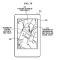
- FIG. 3F is a diagram illustrates that the touch sensing unit 201 differentiates the first touch and the second touch from each other, according to an embodiment of the present invention.
- the touch sensing unit 201 may differentiate the first touch and the second touch from each other, with reference to a predetermined distance.
- the touch sensing unit 201 recognizes this movement as the second touch.
- the touch sensing unit 201 may differentiate the first and second touches from each other, depending on whether a pressure is applied onto the locations of the first and second touches.
- a pointer is set to the touched location, and if the user makes a second touch without pressing the touched location, the touch sensing unit 201 recognizes it as the second touch.
- the coordinate transforming unit 203 reflects the coordinates of the location of the second touch, which are changed whenever the user changes the location of the second touch, into the coordinates of the location of the first touch, i.e., into the coordinates of the location of the pointer.
- FIG. 3G is a diagram illustrating that the movement of the location of the second touch is reflected into the movement of the location of the pointer, according to an embodiment of the present invention.
- FIG. 3G illustrates a pointer 326 that is moved by the coordinate transforming unit 203 as described above.
- the coordinate transforming unit 203 is capable of transforming the movement of the location of the second touch into movement of the location of the pointer at a ratio of 1 to 1.
- the current location of the pointer is also moved on the screen by 3 cm and in a right direction.
- the coordinate transforming unit 203 is also capable of transforming the movement of the location of the second touch into the movement of the location of the pointer at a ratio of 1 to N.
- the location of the second touch is moved on the screen by 3 cm and in a left direction
- the current location of the pointer is moved by 1 cm, 0.5 cm, or less than 0.5 cm and in a left direction according to a ratio of transformation.
- the present invention allows a pointer to be minutely moved, thereby improving usability of the apparatuses.
- the apparatus is capable of not only moving a pointer based on a first touch and a second touch, but also rotating a map by inputting an input of predetermined mode conversion using a button (not shown) or a touch (not shown).
- FIG. 3H is a diagram illustrating a method of rotating a map, according to an embodiment of the invention.
- the touch sensing unit 201 senses the first touch and detects the touched location 321 of the first touch
- the pointer setting unit 202 sets the pointer 322 to the location 321 of the first touch, and the second touch is made, a user can rotate a map to a desired extent by using a rotation conversion button (not shown) or a touch activator for rotation conversion (not shown).
- the map is rotated with respect to the location 321 of the first touch, and the user can adjust the extent of the rotation by moving the location of the second touch.
- the coordinate transforming unit 203 is capable of precisely adjusting the rotation of the map with respect to the pointer according to the movement of the location of the second touch, at the above ratio of the movement of the location of the second touch to the movement of the location of the pointer, e.g., at a ratio of 1 to 1 or a ratio of 1 to N.
- the pressure sensing unit 204 senses pressures applied onto the locations of the first and second touches, which are detected by the touch sensing unit 201 to instruct an operation corresponding to each of the sensed pressures to be performed.
- the pressure sensing unit 204 may instruct an operation corresponding to the sensed pressure to be performed according to the duration and intensity of the sensed pressure.
- the speed of the zoom-in operation or the zoom-out operation may be controlled according to the intensity of the pressure.
- the pressure is low, it is possible to reduce the speed of the zoom-in operation or the zoom-out operation, and if the pressure is high, it is possible to increase the speed of the zoom-in operation or the zoom-out operation.
- FIGS. 3I and 3J are diagrams illustrating how an operation to be performed is instructed by a pressure sensing unit according to an embodiment of the present invention.
- the pressure sensing unit 204 requests the display unit 205 to display information 327 regarding the location of the first touch on a map as illustrated in FIG. 3I .
- the information 327 may include the name, address, latitude, and longitude of the location of the first touch.
- the pressure sensing unit 204 may present an effect of clicking a left button or a right button of a mouse.
- a pressure is applied onto the touched location of the second touch without moving the location of the second touch, it is possible to obtain an effect of clicking the left button of a mouse.
- a pressure is applied onto the location of the second touch without moving the location of the second touch for a predetermined duration of time, e.g., for 2 seconds, an effect of clicking the right button of the mouse is achieved thus popping up an attribute window 328.
- duration and intensity of a pressure applied according to the present invention may be determined in various manners, without being intended to be limiting.
- FIG. 4 is a flowchart illustrating a method of improving usability of a touch screen, according to an embodiment of the present invention.
- FIG. 4 The flowchart, of FIG. 4 , illustrating a method of improving usability of a touch screen according to an embodiment of the present invention, will now be described with reference to FIG. 2 .
- the touch sensing unit 201 senses a user's first touch and detects the touched location of the first touch (S401). After operation S401, the touch sensing unit 201 determines whether the first touch is canceled (S402).
- the pointer setting unit 202 sets a pointer to the location of the first touch (S403).
- the touch sensing unit 201 senses the user' s second touch and detects the touched location of the second touch (S404).
- the touch sensing unit 201 can recognize the second touch, since it is made after the first touch is canceled, that is, since it is made a predetermined interval of time after the first touch.
- the pressure sensingunit 204 determines whether a pressure is applied onto the location of the second touch (5405) .
- the touch sensing unit 201 senses movement of the user's second touch, and detects the location of the moved second touch (S406).
- the pressure sensing unit 204 performs operations S412 and S413 which will later be described.
- the coordinate transforming unit 203 reflects the movement of the location of the second touch determined in operation S405 by transforming the movement of the location of the second touch into movement of the pointer (S407).
- the coordinate transforming unit 203 is capable of precisely controlling the movement of the pointer based on the second touch by reflecting the movement of the pointer with respect to the movement of the second touch at a ratio of 1 to 1 or at a ratio of 1 to N.
- the movement of the pointer is displayed on the display unit 205 (S408). If it is determined in operation S402 that the first touch is not canceled, the touch sensing unit 201 determines whether the location of the first touch is moved (5409) .
- the touch sensing unit 201 determines this movement as the second touch and the pointer setting unit 202 sets a pointer to the original location of the first touch (S410).
- the touch sensing unit 201 continuously senses the first touch and detects the touched location of the first touch.
- the pressure sensing unit 204 determines whether a pressure is applied onto the location of the first touch (5411).
- the display unit 205 displays the instructed operation (5413).
- the above apparatus and method for improving usability of a touch screen according to the present invention have one or more advantages as follows.
- the present invention has an advantage of preventing a desired screen image from being partially hidden by part of a user' s body, e.g., a finger, or a tool, such as a stylus pen.
Landscapes
- Engineering & Computer Science (AREA)
- General Engineering & Computer Science (AREA)
- Theoretical Computer Science (AREA)
- Human Computer Interaction (AREA)
- Physics & Mathematics (AREA)
- General Physics & Mathematics (AREA)
- Position Input By Displaying (AREA)
- User Interface Of Digital Computer (AREA)
- Devices For Indicating Variable Information By Combining Individual Elements (AREA)
Abstract
Description
- The present invention relates to an apparatus and method for improving usability of a touch screen, and more particularly, to an apparatus and method for improving usability of a touch screen, which are capable of preventing a desired screen image displayed on a location based service (LBS) apparatus from being partially hidden by a part of a user's body, such as a finger, or a tool, such as a stylus pen, and precisely controlling the operation of a pointer.
- Location based services (LBS) indicate various types of services that provide a terminal user with location-related information from a geographic information system (GIS), a global positioning system (GPS), or Telematics, based on the location of a mobile communication terminal, such as a mobile phone or a personal digital assistant (PDA). An LBS employs the triangular network method in which a current location is detected simultaneously by 3 base stations, or a GPS-based method. LBSs have recently been applied to the fields of location information and traffic navigation, and further, to the field of private sector services, such as mobile advertisements, mobile coupons, travel information, vehicle diagnosis supports, emergency operations, and taxi call services.
-
FIGS. 1A and1B illustrate that a map is displayed on aconventional LBS apparatus 110 through map browsing. - Here, it is assumed that the
LBS apparatus 110 illustrated inFIGS. 1A and1B employs a touch screen technique in which a user can move and search for a map and refer to information regarding a specific location on the map by touching theLBS apparatus 110. As illustrated inFIG. 1A , a map is displayed on ascreen 111 of theLBS apparatus 110, and a user can see the latitude, longitude, name, and address of aspecific location 111a on the map by touching thelocation 111a of the map on thescreen 111. - In this case, as illustrated in
FIG. 1B , not only thelocation 111a but also neighbor locations are hidden by a part of the body of the user, e.g., afinger 120, which touches thelocation 111a. - Also, as described above, LBSs have been recently, actively applied to private sectors, thus increasing demand for LBS apparatuses. Further, as the sizes of digital apparatuses become smaller and smaller, it is quite difficult to delicately manipulate a touch screen, which is accordingly becoming smaller and smaller, by part of a user's body, e.g., the
finger 120. - The present invention provides an apparatus and method for improving usability of a touch screen, which are capable of preventing part of a user's body, e.g., a finger, from obstructing a user' s field of vision in a locationbased service (LBS) apparatus.
- The present invention also allows a user to precisely move and search for a map on an LBS apparatus with a touch screen.
- These and other objects of the present invention will be described in or be apparent from the following description of the preferred embodiments.
- According to an aspect of the present invention, there is provided an apparatus for improving usability of a touch screen, the apparatus including a touch sensing unit that senses a first touch and a second touch and detects the locations of the sensed touches, a pointer setting unit that sets a pointer to the detected location of the first touch, and a coordinate transforming unit that transforms movement of a touched location, which is caused by movement of the second touch, into movement of the location of the pointer.
- According to another aspect of the present invention, there is provided a method of improving usability of a touch screen, the method comprising: sensing a first touch, and detecting a touched location of the sensed first touch, setting a pointer to the detected location of the first touch, sensing a second touch, and detecting a touched location of the sensed second touch, and transforming movement of a touched location, which is caused by movement of the second touch, into movement of a location of the pointer.
- The above and other features and advantages of the present invention will become more apparent by describing in detail preferred embodiments thereof with reference to the attached drawings in which:
-
FIGS. 1A and1B illustrate that a map is displayed on a conventional location based service (LBS) apparatus through map browsing; -
FIG. 2A is a block diagram of an apparatus for improving usability of a touch screen, according to an embodiment of the present invention; -
FIG. 2B is a diagram illustrating a case where an apparatus for improving usability of a touch screen is actually applied to an LBS apparatus, according to an embodiment of the present invention; -
FIGS. 3A and3B are diagrams illustrating a first touch made by a user according to an embodiment of the present invention; -
FIG. 3C is a diagram illustrating setting of a pointer according to an embodiment of the present invention; -
FIGS. 3D and3E are diagrams illustrating movement of a touched location, which is caused by movement of the location of a second touch, according to an embodiment of the present invention; -
FIG. 3F is a diagram illustrating that a touch sensing unit differentiates the first touch and the second touch from each other, according to an embodiment of the present invention; -
FIG. 3G is a diagram illustrating reflecting of movement of the location of the second touch into movement of the pointer, according to an embodiment of the present invention; -
FIG. 3H is a diagram illustrating a method of rotating a map according to an embodiment of the present invention; -
FIG. 3I and3J are diagrams illustrating how an operation to be performed is instructed by a pressure sensing unit according to an embodiment of the present invention; and -
FIG. 4 is a flowchart illustrating a method of improving usability of a touch screen, according to an embodiment of the present invention. - Advantages and features of the present invention and methods of accomplishing the same may be understood more readily by reference to the following detailed description of preferred embodiments and the accompanying drawings. The present invention may, however, be embodied in many different forms and should not be construed as being limited to the embodiments set forth herein. Rather, these embodiments are provided so that this disclosure will be thorough and complete and will fully convey the concept of the invention to those skilled in the art, and the present invention will only be defined by the appended claims.
- Like reference numerals refer to like elements throughout the specification.
- The present invention is described hereinafter with reference to flowchart illustrations of methods according to exemplary embodiments of the invention.
- It will be understood that each block of the flowchart illustrations, and combinations of blocks in the flowchart illustrations, can be implemented by computer program instructions. These computer program instructions can be provided to a processor of a general purpose computer, special purpose computer, or other programmable data processing apparatus to create means for implementing the functions specified in the flowchart block or blocks.
- These computer program instructions may also be stored in a computer usable or computer-readable memory that can direct a computer or other programmable data processing apparatus to function in a particular manner, such that the instructions implement the function specified in the flowchart block or blocks.
- The computer program instructions may also be loaded onto a computer or other programmable data processing apparatus to cause a series of operational steps to be performed on the computer or other programmable apparatus to produce a computer implemented process for implementing the functions specified in the flowchart block or blocks.
- In addition, each block may represent a module, a segment, or a portion of code, which may comprise one or more executable instructions for implementing the specified logical functions. It should also be noted that in other implementations, the functions noted in the blocks may occur out of the order noted or in different configurations of hardware and software. For example, two blocks shown in succession may, in fact, be executed substantially concurrently, or the blocks may sometimes be executed in the reverse order, depending on the functionality involved.
- In exemplary embodiments of the present invention, it is assumed that a map is displayed on a touch screen of a location based service (LBS) apparatus and a user selects a desired location on the map. Hereinafter, exemplary embodiments of the present invention will be described in detail with reference to the accompanying drawings.
-
FIG. 2A is a block diagram of an apparatus for improving usability of a touch screen, according to an embodiment of the present invention. - Referring to
FIG. 2A , anapparatus 200 for improving usability of a touch screen according to an embodiment of the present invention, includes atouch sensing unit 201 that senses a first touch and a second touch and detects the touched locations of the sensed touches, apointer setting unit 202 that sets a pointer to the touched location of the first touch, which is detected by thetouch sensing unit 201, a coordinate transformingunit 203 that transforms movement of a touched location, which is caused by movement of the second touch, into movement of the location of the pointer, apressure sensing unit 204 that senses a pressure applied to the touched location detected by thetouch sensing unit 201 to instruct an operation corresponding to the sensed pressure to be performed, and adisplay unit 205 that displays movement of the location of the pointer and the operation corresponding to the sensed pressure. As illustrated inFIG. 2B , theapparatus 200 ofFIG. 2A can be applied to LBS apparatuses. - The
touch sensing unit 201 may include a touch sensor in order to sense a user's touch, and be located on the top of thedisplay unit 205 which is a screen of the LBS apparatus. Thepressure sensing unit 204 senses a pressure applied to the touched location. One or morepressure sensing units 204 may be located at the bottom of thedisplay unit 205. - Meanwhile, the term 'unit', as used in
FIG. 2A , means, but is not limited to, a software or hardware component, such as a Field Programmable Gate Array (FPGA) or Application Specific Integrated Circuit (ASIC), which performs certain tasks. - A unit may advantageously be configured to reside on the addressable storage medium and configured to execute on one or more processors.
- Thus, a unit may include, by way of example, components, such as software components, object-oriented software components, class components and task components, processes, functions, attributes, procedures, subroutines, segments of program code, drivers, firmware, microcode, circuitry, data, databases, data structures, tables, arrays, and variables.
- The functionality provided for in the components and units maybe combined into fewer components and units or further separated into additional components and units.
First, thetouch sensing unit 201 of theapparatus 200 ofFIG. 2A senses the first touch and the second touch, and detects the touched locations of the sensed touches. - The first touch indicates the user's touch of a desired location on the screen of the LBS apparatus by using an object. Here, the object means a part of the body of the user, such as a finger, or a tool, such as a stylus pen.
- Hereinafter, for convenience of explanation, it is assumed in embodiments of the present invention that a part of the body of the user, e.g., a finger, is used in order to apply an input to an LBS apparatus. The second touch and the
touch sensing unit 201 will be described in greater detail when describing theother elements 202 through 205 illustrated inFIG. 2A . -
FIGS. 3A and3B are diagrams illustrating a first touch made by a user according to an embodiment of the present invention. - Referring to
FIG. 3A , a map is displayed on ascreen 320 of anLBS apparatus 310, and a user touches a desiredlocation 321 on the map with his/herfinger 330. -
FIG. 3B illustrates thelocation 321 of a first touch of the desiredlocation 321 illustrated inFIG. 3A , which is touched by the user'sfinger 330. - In this case, the
touch sensing unit 201 senses the first touch and detects the touchedlocation 321 of the first touch. -
FIG. 3C is a diagram illustrating setting of a pointer according to an embodiment of the present invention. - Referring to
FIG. 3C , thepointer setting unit 202 sets apointer 322 to the touchedlocation 321 of the first touch, which is detected by thetouch sensing unit 201. - At this time, as illustrated in
FIG. 3C , the user'sfinger 330 is separated from thelocation 321 of the first touch. - The
pointer setting unit 202 sets thepointer 322, that is, it places thepointer 322 at thelocation 321 of the first touch, when the user touches and then stops touching thelocation 321 of the first touch or when the user touches thelocation 321 and then moves a predetermined distance from thelocation 321 of the first touch. - The above operation of the
pointer setting unit 202 is closely related to an operation of thetouch sensing unit 201 that differentiates the first and second touches from each other, which will later be described with reference toFIG. 3F . -
FIGS. 3D and3E illustrate movement of a touched location, which is caused by movement of the second touch, according to an embodiment of the present invention. - The
touch sensing unit 201 sensed the first touch and detected the touchedlocation 321 of the first touch, and thepointer setting unit 202 set thepointer 322 to the touchedlocation 321 of the first touch, as described above with reference toFIGS. 3A through 3C . - Next, when the user determines an estimated
location 323 of the second touch on thescreen 320 of theLBS apparatus 310 as illustrated inFIG. 3D , and touches thedetermined location 323 as illustrated inFIG. 3E , thetouch sensing unit 201 senses the second touch and detects the touchedlocation 323 of the second touch. - The coordinate transforming
unit 203 receives information regarding the touchedlocations touch sensing unit 201, and transforms movement of the touched location 323 (alocation 324 illustrated inFIG. 3E ), which is caused by movement of the second touch, into movement of the location of thepointer 322. - Here, the second touch means the user's touch made in order to control movement of the
pointer 322 set to the touchedlocation 321 of the first touch. As illustrated inFIG. 3E , thelocation 323 of the second touch is preferably determined to be a region in which it is convenient to control the movement of thepointer 322 that is set to thelocation 321 of the first touch on thescreen 320 of theLBS apparatus 310. - The
touch sensing unit 201 differentiates the first touch and the second touch from each other, with reference to a predetermined instant of time. - For example, as illustrated in
FIG. 3C , when after the user' s first touch, the user cancels the first touch and touches a new location rather than thelocation 321 of the first touch, thetouch sensing unit 201 recognizes the touch of the new location as the second touch. -
FIG. 3F is a diagram illustrates that thetouch sensing unit 201 differentiates the first touch and the second touch from each other, according to an embodiment of the present invention. - The
touch sensing unit 201 may differentiate the first touch and the second touch from each other, with reference to a predetermined distance. - For example, after the user' s first touch, when the user moves the predetermined distance from the first touch while maintaining the first touch, that is, when the user moves to the outside of a
predetermined boundary 325 from thelocation 321 of the first touch, thetouch sensing unit 201 recognizes this movement as the second touch. - Also, the
touch sensing unit 201 may differentiate the first and second touches from each other, depending on whether a pressure is applied onto the locations of the first and second touches. - For example, if the user makes a first touch and presses the touched location at the same time, a pointer is set to the touched location, and if the user makes a second touch without pressing the touched location, the
touch sensing unit 201 recognizes it as the second touch. - Since the touched locations of the first touch and the second touch, that is, the coordinates of the touched locations of the first and second touches, are known, the coordinate transforming
unit 203 reflects the coordinates of the location of the second touch, which are changed whenever the user changes the location of the second touch, into the coordinates of the location of the first touch, i.e., into the coordinates of the location of the pointer. - Accordingly, the movement of the location of the user' s second touch is transformed into the movement of the location of the pointer.
-
FIG. 3G is a diagram illustrating that the movement of the location of the second touch is reflected into the movement of the location of the pointer, according to an embodiment of the present invention. - If the initial, touched
location 323 of the second touch is changed to a new touchedlocation 324, thetouch sensing unit 201 detects the coordinates of thenew location 324, and reflects in real time the detected coordinates into the coordinates of thepointer 322 that is set to the location of the first touch, thereby moving thepointer 322.FIG. 3G illustrates apointer 326 that is moved by the coordinate transformingunit 203 as described above. - In this case, the coordinate transforming
unit 203 is capable of transforming the movement of the location of the second touch into movement of the location of the pointer at a ratio of 1 to 1. - For example, if the location of the second touch is moved on the screen by 3 cm and in a right direction, the current location of the pointer is also moved on the screen by 3 cm and in a right direction.
- The coordinate transforming
unit 203 is also capable of transforming the movement of the location of the second touch into the movement of the location of the pointer at a ratio of 1 to N. - For example, the location of the second touch is moved on the screen by 3 cm and in a left direction, the current location of the pointer is moved by 1 cm, 0.5 cm, or less than 0.5 cm and in a left direction according to a ratio of transformation. In this case, even if the scale of a map displayed on a screen of an OBS apparatus is high, it is possible to minutelymove the pointer on the map. Further, as not only a screen of each LBS apparatus but also a touch screen of each of most digital apparatuses become smaller and smaller, the present invention allows a pointer to be minutely moved, thereby improving usability of the apparatuses.
- Further, the apparatus according to an embodiment of the present invention is capable of not only moving a pointer based on a first touch and a second touch, but also rotating a map by inputting an input of predetermined mode conversion using a button (not shown) or a touch (not shown).
-
FIG. 3H is a diagram illustrating a method of rotating a map, according to an embodiment of the invention. - As illustrated in
FIG. 3E , if thetouch sensing unit 201 senses the first touch and detects the touchedlocation 321 of the first touch, thepointer setting unit 202 sets thepointer 322 to thelocation 321 of the first touch, and the second touch is made, a user can rotate a map to a desired extent by using a rotation conversion button (not shown) or a touch activator for rotation conversion (not shown). - In this case, as illustrated in
FIG. 3H , the map is rotated with respect to thelocation 321 of the first touch, and the user can adjust the extent of the rotation by moving the location of the second touch. - The coordinate transforming
unit 203 is capable of precisely adjusting the rotation of the map with respect to the pointer according to the movement of the location of the second touch, at the above ratio of the movement of the location of the second touch to the movement of the location of the pointer, e.g., at a ratio of 1 to 1 or a ratio of 1 to N. - The
pressure sensing unit 204 senses pressures applied onto the locations of the first and second touches, which are detected by thetouch sensing unit 201 to instruct an operation corresponding to each of the sensed pressures to be performed. - Also, the
pressure sensing unit 204 may instruct an operation corresponding to the sensed pressure to be performed according to the duration and intensity of the sensed pressure. - For example, when a zoom-in operation or a zoom-out operation is to be performed on the map, the speed of the zoom-in operation or the zoom-out operation may be controlled according to the intensity of the pressure.
- If the pressure is low, it is possible to reduce the speed of the zoom-in operation or the zoom-out operation, and if the pressure is high, it is possible to increase the speed of the zoom-in operation or the zoom-out operation.
-
FIGS. 3I and3J are diagrams illustrating how an operation to be performed is instructed by a pressure sensing unit according to an embodiment of the present invention. - For example, when after a first touch, a pressure is applied onto the touched location of the first touch without moving the location of the first touch for a predetermined duration of time, the
pressure sensing unit 204 requests thedisplay unit 205 to displayinformation 327 regarding the location of the first touch on a map as illustrated inFIG. 3I . - Here, the
information 327 may include the name, address, latitude, and longitude of the location of the first touch. - Also, if after a second touch, a pressure is applied onto the touched location of the second touch without moving the location of the second touch for a predetermined duration of time, the
pressure sensing unit 204 may present an effect of clicking a left button or a right button of a mouse. - For example, when after the second touch, a pressure is applied onto the touched location of the second touch without moving the location of the second touch, it is possible to obtain an effect of clicking the left button of a mouse. Also, as illustrated in
FIG. 3J , when after a second touch, a pressure is applied onto the location of the second touch without moving the location of the second touch for a predetermined duration of time, e.g., for 2 seconds, an effect of clicking the right button of the mouse is achieved thus popping up anattribute window 328. - The duration and intensity of a pressure applied according to the present invention may be determined in various manners, without being intended to be limiting.
-
FIG. 4 is a flowchart illustrating a method of improving usability of a touch screen, according to an embodiment of the present invention. - The flowchart, of
FIG. 4 , illustrating a method of improving usability of a touch screen according to an embodiment of the present invention, will now be described with reference toFIG. 2 . - The
touch sensing unit 201 senses a user's first touch and detects the touched location of the first touch (S401). After operation S401, thetouch sensing unit 201 determines whether the first touch is canceled (S402). - If it is determined in operation S402 that the first touch is canceled, the
pointer setting unit 202 sets a pointer to the location of the first touch (S403). - After operation S403, the
touch sensing unit 201 senses the user' s second touch and detects the touched location of the second touch (S404). - In this case, the
touch sensing unit 201 can recognize the second touch, since it is made after the first touch is canceled, that is, since it is made a predetermined interval of time after the first touch. - After operation S404, the
pressure sensingunit 204 determines whether a pressure is applied onto the location of the second touch (5405) . - If it is determined in operation S405 that a pressure is not applied, the
touch sensing unit 201 senses movement of the user's second touch, and detects the location of the moved second touch (S406). - If it is determined in operation S405 that a pressure is applied onto the location of the second touch, the
pressure sensing unit 204 performs operations S412 and S413 which will later be described. - After operation S406, the coordinate transforming
unit 203 reflects the movement of the location of the second touch determined in operation S405 by transforming the movement of the location of the second touch into movement of the pointer (S407). - In this case, the coordinate transforming
unit 203 is capable of precisely controlling the movement of the pointer based on the second touch by reflecting the movement of the pointer with respect to the movement of the second touch at a ratio of 1 to 1 or at a ratio of 1 to N. - After operation S407, the movement of the pointer is displayed on the display unit 205 (S408). If it is determined in operation S402 that the first touch is not canceled, the
touch sensing unit 201 determines whether the location of the first touch is moved (5409) . - If it is determined in operation S409 that the first touch is moved to the outside of a predetermined range, the
touch sensing unit 201 determines this movement as the second touch and thepointer setting unit 202 sets a pointer to the original location of the first touch (S410). - If it is determined in operation S409 that the movement of the first touch falls within the predetermined range, the
touch sensing unit 201 continuously senses the first touch and detects the touched location of the first touch. - If it is determined in operation S409 that the location of the first touch is not moved, the
pressure sensing unit 204 determines whether a pressure is applied onto the location of the first touch (5411). - If it is determined in operation 5411 that a pressure is applied, the duration and intensity of the applied pressure are detected, and performing of an operation corresponding to the detected duration and intensity of the pressure is instructed (5412).
- After operation S412, the
display unit 205 displays the instructed operation (5413). - The above apparatus and method for improving usability of a touch screen according to the present invention have one or more advantages as follows.
- The present invention has an advantage of preventing a desired screen image from being partially hidden by part of a user' s body, e.g., a finger, or a tool, such as a stylus pen.
- Also, it is possible to precisely control movement of a pointer or an operation that is to be performed using the pointer, based on a first touch and a second touch.
- Also, it is possible to precisely control movement of a pointer or an operation that is to be performed using a pointer without enlarging the size of a screen image, thereby minimizing the size of an LBS apparatus.
- While the present invention has been particularly shown and described with reference to exemplary embodiments thereof, it will be understood by those of ordinary skill in the art that various changes in form and details may be made therein without departing from the spirit and scope of the present invention as defined by the following claims. It is therefore desired that the present embodiments be considered in all respects as illustrative and not restrictive, reference being made to the appended claims rather than the foregoing description to indicate the scope of the invention.
Claims (14)
- An apparatus for improving usability of a touch screen, the apparatus comprising:a touch sensing unit sensing a first touch and a second touch, and detecting touched locations of the sensed touches;a pointer setting unit setting a pointer to the detected location of the first touch; anda coordinate transforming unit transforming movement of a touched location, which is caused by movement of the second touch, into movement of a location of the pointer.
- The apparatus of claim 1, further comprising a pressure sensingunit sensing pressure applied to the locations of the sensed touches to instruct an operation corresponding to the sensed pressure to be performed.
- The apparatus of claim 2, wherein the operation instructed by the pressure sensing unit is performed according to one of a duration and intensity of the sensed pressure.
- The apparatus of claim 1, wherein the touch sensing unit differentiates the first touch and the second touch from each other with reference to a predetermined instant of time.
- The apparatus of claim 1, wherein the touch sensing unit differentiates the first touch and the second touch from each other with reference to a predetermined distance.
- The apparatus of claim 1, wherein the coordinate transforming unit transforms movement of the touched location, which is caused by movement of the second touch, into movement of a location of the pointer at a ratio of 1 to 1.
- The apparatus of claim 1, wherein the coordinate transforming unit transforms movement of the touched location, which is caused by movement of the second touch, into movement of a location of the pointer at a ratio of 1 to N.
- A method of improving usability of a touch screen, the method comprising:sensing a first touch, and detecting a touched location of the sensed first touch;setting a pointer to the detected location of the first touch;sensing a second touch, and detecting a touched location of the sensed second touch; andtransforming movement of a touched location, which is caused by movement of the second touch, into movement of a location of the pointer.
- The method of claim 8, further comprising sensing a pressure applied to the touched location to instruct an operation corresponding to the sensed pressure to be performed.
- The method of claim 9, wherein the operation instructed in the sensing of the pressure is performed according to one of a duration and intensity of the sensed pressure.
- The method of claim 9, wherein the sensing of the second touch comprises differentiating the first touch and the second touch from each other with reference to a predetermined instant of time.
- The method of claim 8, wherein the sensing of the second touch comprises differentiating the first touch and the second touch from each other with reference to a predetermined distance.
- The method of claim 8, wherein the transforming of the movement of the touched location comprises transforming movement of the touched location, which is caused by movement of the second touch, into movement of a location of the pointer at a ratio of 1 to 1.
- The method of claim 8, wherein the transforming of the movement of the touched location comprises transforming movement of the touched location, which is caused by movement of the second touch, into movement of a location of the pointer at a ratio of 1 to N.
Applications Claiming Priority (1)
| Application Number | Priority Date | Filing Date | Title |
|---|---|---|---|
| KR1020070007972A KR100891099B1 (en) | 2007-01-25 | 2007-01-25 | Touch screen and method for improvement of usability in touch screen |
Publications (3)
| Publication Number | Publication Date |
|---|---|
| EP1950653A2 true EP1950653A2 (en) | 2008-07-30 |
| EP1950653A3 EP1950653A3 (en) | 2009-07-08 |
| EP1950653B1 EP1950653B1 (en) | 2018-08-29 |
Family
ID=39415137
Family Applications (1)
| Application Number | Title | Priority Date | Filing Date |
|---|---|---|---|
| EP08100613.2A Active EP1950653B1 (en) | 2007-01-25 | 2008-01-17 | Apparatus and method for improvement of usability of touch screen |
Country Status (5)
| Country | Link |
|---|---|
| US (1) | US8760410B2 (en) |
| EP (1) | EP1950653B1 (en) |
| JP (2) | JP5448346B2 (en) |
| KR (1) | KR100891099B1 (en) |
| CN (1) | CN101231564B (en) |
Cited By (3)
| Publication number | Priority date | Publication date | Assignee | Title |
|---|---|---|---|---|
| FR2948808A1 (en) * | 2009-07-30 | 2011-02-04 | Dassault Aviat | DIGITAL DISPLAY DEVICE, IN PARTICULAR FOR THE PREPARATION OF A PATH |
| EP2458487A1 (en) * | 2009-09-02 | 2012-05-30 | Sony Corporation | Operation control device, operation control method and computer program |
| EP2851765B1 (en) * | 2012-06-20 | 2017-08-23 | ZTE Corporation | Method for reporting coordinate point of touch screen and mobile terminal |
Families Citing this family (69)
| Publication number | Priority date | Publication date | Assignee | Title |
|---|---|---|---|---|
| US10983665B2 (en) | 2008-08-01 | 2021-04-20 | Samsung Electronics Co., Ltd. | Electronic apparatus and method for implementing user interface |
| JP2010049460A (en) * | 2008-08-21 | 2010-03-04 | Denso Corp | Operation input device |
| US8384687B2 (en) * | 2008-08-21 | 2013-02-26 | Denso Corporation | Manipulation input apparatus |
| US20100060588A1 (en) * | 2008-09-09 | 2010-03-11 | Microsoft Corporation | Temporally separate touch input |
| US8427424B2 (en) * | 2008-09-30 | 2013-04-23 | Microsoft Corporation | Using physical objects in conjunction with an interactive surface |
| KR101507840B1 (en) * | 2008-10-23 | 2015-04-03 | 엘지전자 주식회사 | A mobile telecommunication device and a method of controlling a touch screen |
| US20100162181A1 (en) * | 2008-12-22 | 2010-06-24 | Palm, Inc. | Interpreting Gesture Input Including Introduction Or Removal Of A Point Of Contact While A Gesture Is In Progress |
| JP2010176330A (en) * | 2009-01-28 | 2010-08-12 | Sony Corp | Information processing apparatus and display control method |
| DE102009008041A1 (en) * | 2009-02-09 | 2010-08-12 | Volkswagen Ag | Method for operating a motor vehicle with a touchscreen |
| KR101062594B1 (en) * | 2009-03-19 | 2011-09-06 | 김연수 | Touch screen with pointer display |
| JP5325979B2 (en) * | 2009-04-24 | 2013-10-23 | 京セラ株式会社 | Input device |
| US20100283722A1 (en) * | 2009-05-08 | 2010-11-11 | Sony Ericsson Mobile Communications Ab | Electronic apparatus including a coordinate input surface and method for controlling such an electronic apparatus |
| US8355007B2 (en) * | 2009-05-11 | 2013-01-15 | Adobe Systems Incorporated | Methods for use with multi-touch displays for determining when a touch is processed as a mouse event |
| JP5173924B2 (en) * | 2009-05-12 | 2013-04-03 | 京セラドキュメントソリューションズ株式会社 | Image forming apparatus |
| US8441465B2 (en) | 2009-08-17 | 2013-05-14 | Nokia Corporation | Apparatus comprising an optically transparent sheet and related methods |
| CN102033684B (en) * | 2009-09-30 | 2013-01-02 | 万达光电科技股份有限公司 | Gesture sensing method for touch panel |
| TW201115419A (en) * | 2009-10-29 | 2011-05-01 | Sentelic Corp | Touch-sensing method and electronic device |
| CN102103452A (en) * | 2009-12-17 | 2011-06-22 | 深圳富泰宏精密工业有限公司 | Flying spot control system and method |
| US8730309B2 (en) | 2010-02-23 | 2014-05-20 | Microsoft Corporation | Projectors and depth cameras for deviceless augmented reality and interaction |
| US20110224896A1 (en) * | 2010-03-09 | 2011-09-15 | Nokia Corporation | Method and apparatus for providing touch based routing services |
| KR101572892B1 (en) | 2010-05-06 | 2015-11-30 | 엘지전자 주식회사 | Mobile terminal and Method for displying image thereof |
| KR101694157B1 (en) * | 2010-05-11 | 2017-01-09 | 엘지전자 주식회사 | Mobile terminal and operation control method thereof |
| US8640020B2 (en) * | 2010-06-02 | 2014-01-28 | Microsoft Corporation | Adjustable and progressive mobile device street view |
| US9329469B2 (en) | 2011-02-17 | 2016-05-03 | Microsoft Technology Licensing, Llc | Providing an interactive experience using a 3D depth camera and a 3D projector |
| US9480907B2 (en) | 2011-03-02 | 2016-11-01 | Microsoft Technology Licensing, Llc | Immersive display with peripheral illusions |
| US9597587B2 (en) | 2011-06-08 | 2017-03-21 | Microsoft Technology Licensing, Llc | Locational node device |
| US8643616B1 (en) | 2011-07-29 | 2014-02-04 | Adobe Systems Incorporated | Cursor positioning on a touch-sensitive display screen |
| EP2562628A1 (en) * | 2011-08-26 | 2013-02-27 | Sony Ericsson Mobile Communications AB | Image scale alteration arrangement and method |
| US9274632B2 (en) * | 2011-09-27 | 2016-03-01 | Nec Corporation | Portable electronic device, touch operation processing method, and program |
| JP2013080412A (en) * | 2011-10-05 | 2013-05-02 | Sony Corp | Information processing device, information processing method, and program |
| KR101123886B1 (en) * | 2011-10-26 | 2012-03-23 | 주식회사 한글과컴퓨터 | Touch screen apparatus and touch screen display size adjustment method |
| KR101338825B1 (en) | 2011-12-14 | 2013-12-06 | 현대자동차주식회사 | A controlling method and apparatus for display particular in selected area by using dynamic touch interaction |
| US9075566B2 (en) | 2012-03-02 | 2015-07-07 | Microsoft Technoogy Licensing, LLC | Flexible hinge spine |
| US9134807B2 (en) | 2012-03-02 | 2015-09-15 | Microsoft Technology Licensing, Llc | Pressure sensitive key normalization |
| KR101690261B1 (en) * | 2012-04-02 | 2016-12-27 | 삼성전자주식회사 | Digital image processing apparatus and controlling method thereof |
| EP2847661A2 (en) * | 2012-05-09 | 2015-03-18 | Apple Inc. | Device, method, and graphical user interface for moving and dropping a user interface object |
| US20130300590A1 (en) | 2012-05-14 | 2013-11-14 | Paul Henry Dietz | Audio Feedback |
| CN103425311A (en) * | 2012-05-25 | 2013-12-04 | 捷达世软件(深圳)有限公司 | Positioning method and positioning system for mobile object clicking selection |
| US9487388B2 (en) | 2012-06-21 | 2016-11-08 | Nextinput, Inc. | Ruggedized MEMS force die |
| CN103513908B (en) * | 2012-06-29 | 2017-03-29 | 国际商业机器公司 | For controlling light target method and apparatus on the touchscreen |
| JP2014010777A (en) * | 2012-07-02 | 2014-01-20 | Fujitsu Ltd | Display program, display method, and information processing device |
| US9032818B2 (en) | 2012-07-05 | 2015-05-19 | Nextinput, Inc. | Microelectromechanical load sensor and methods of manufacturing the same |
| JP6015183B2 (en) * | 2012-07-18 | 2016-10-26 | 富士ゼロックス株式会社 | Information processing apparatus and program |
| JP2014044605A (en) * | 2012-08-28 | 2014-03-13 | Fujifilm Corp | Input control device and method in touch-sensitive display, and program |
| KR101404505B1 (en) * | 2012-09-24 | 2014-06-09 | (주)이스트소프트 | Method for manipulating scale and/or rotation of graphic in electronic device with display, and electronic device for implementing the same |
| US10139937B2 (en) * | 2012-10-12 | 2018-11-27 | Microsoft Technology Licensing, Llc | Multi-modal user expressions and user intensity as interactions with an application |
| JP6029453B2 (en) * | 2012-12-21 | 2016-11-24 | 京セラ株式会社 | Portable terminal, cursor display control program, cursor display control method, cursor generation control program, cursor generation control method, icon display program, and icon display method |
| JP5780438B2 (en) * | 2013-05-21 | 2015-09-16 | カシオ計算機株式会社 | Electronic device, position designation method and program |
| CN103530052B (en) * | 2013-09-27 | 2017-09-29 | 华为技术有限公司 | The display methods and user equipment of a kind of interface content |
| CN104679423A (en) * | 2013-12-03 | 2015-06-03 | 方正国际软件(北京)有限公司 | Method and system for accurately positioning geographic position of touch screen |
| EP3094950B1 (en) | 2014-01-13 | 2022-12-21 | Nextinput, Inc. | Miniaturized and ruggedized wafer level mems force sensors |
| US9965173B2 (en) * | 2015-02-13 | 2018-05-08 | Samsung Electronics Co., Ltd. | Apparatus and method for precise multi-touch input |
| US10466119B2 (en) | 2015-06-10 | 2019-11-05 | Nextinput, Inc. | Ruggedized wafer level MEMS force sensor with a tolerance trench |
| CN107168565B (en) * | 2016-03-07 | 2020-05-15 | 敦泰电子有限公司 | Touch device, driving circuit and driving method thereof, and electronic equipment |
| CN107229362A (en) * | 2016-03-25 | 2017-10-03 | 宇龙计算机通信科技(深圳)有限公司 | A kind of touch-control pressure reminding method and device |
| CN107239202B (en) * | 2016-03-29 | 2020-06-30 | 中兴通讯股份有限公司 | Control instruction identification method and device |
| KR101835674B1 (en) * | 2016-04-27 | 2018-03-07 | 연세대학교 산학협력단 | Data input device and method on force touch interaction |
| JP6313395B1 (en) * | 2016-10-17 | 2018-04-18 | グリー株式会社 | Drawing processing method, drawing processing program, and drawing processing apparatus |
| US20180121000A1 (en) * | 2016-10-27 | 2018-05-03 | Microsoft Technology Licensing, Llc | Using pressure to direct user input |
| CN116907693A (en) | 2017-02-09 | 2023-10-20 | 触控解决方案股份有限公司 | Integrated digital force sensor and related manufacturing method |
| US11243125B2 (en) | 2017-02-09 | 2022-02-08 | Nextinput, Inc. | Integrated piezoresistive and piezoelectric fusion force sensor |
| US11221263B2 (en) | 2017-07-19 | 2022-01-11 | Nextinput, Inc. | Microelectromechanical force sensor having a strain transfer layer arranged on the sensor die |
| US11423686B2 (en) | 2017-07-25 | 2022-08-23 | Qorvo Us, Inc. | Integrated fingerprint and force sensor |
| US11243126B2 (en) | 2017-07-27 | 2022-02-08 | Nextinput, Inc. | Wafer bonded piezoresistive and piezoelectric force sensor and related methods of manufacture |
| US11579028B2 (en) | 2017-10-17 | 2023-02-14 | Nextinput, Inc. | Temperature coefficient of offset compensation for force sensor and strain gauge |
| WO2019090057A1 (en) | 2017-11-02 | 2019-05-09 | Nextinput, Inc. | Sealed force sensor with etch stop layer |
| WO2019099821A1 (en) | 2017-11-16 | 2019-05-23 | Nextinput, Inc. | Force attenuator for force sensor |
| JP6863918B2 (en) * | 2018-03-19 | 2021-04-21 | グリー株式会社 | Control programs, control methods and information processing equipment |
| US10962427B2 (en) | 2019-01-10 | 2021-03-30 | Nextinput, Inc. | Slotted MEMS force sensor |
Citations (5)
| Publication number | Priority date | Publication date | Assignee | Title |
|---|---|---|---|---|
| EP0653696A1 (en) | 1993-11-15 | 1995-05-17 | Tektronix, Inc. | Touch control of cursor position |
| US6278443B1 (en) | 1998-04-30 | 2001-08-21 | International Business Machines Corporation | Touch screen with random finger placement and rolling on screen to control the movement of information on-screen |
| EP1191430A1 (en) | 2000-09-22 | 2002-03-27 | Hewlett-Packard Company, A Delaware Corporation | Graphical user interface for devices having small tactile displays |
| US20030146905A1 (en) | 2001-12-20 | 2003-08-07 | Nokia Corporation | Using touchscreen by pointing means |
| EP1674976A2 (en) | 2004-12-22 | 2006-06-28 | Microsoft Corporation | Improving touch screen accuracy |
Family Cites Families (27)
| Publication number | Priority date | Publication date | Assignee | Title |
|---|---|---|---|---|
| US1136749A (en) * | 1909-02-13 | 1915-04-20 | Union Special Machine Co | Feeding mechanism for sewing-machines. |
| JP3103085B2 (en) * | 1989-12-15 | 2000-10-23 | 株式会社東芝 | Display input device |
| JPH0651908A (en) * | 1992-07-28 | 1994-02-25 | Sony Corp | Information processor provided with touch panel type input device |
| JPH07104914A (en) | 1993-09-30 | 1995-04-21 | Toshiba Corp | Touch input device |
| GB2286100A (en) * | 1994-01-19 | 1995-08-02 | Ibm | Touch-sensitive display apparatus |
| JPH09251347A (en) | 1996-03-15 | 1997-09-22 | Matsushita Electric Ind Co Ltd | Coordinate input device |
| US5854625A (en) | 1996-11-06 | 1998-12-29 | Synaptics, Incorporated | Force sensing touchpad |
| JPH11203044A (en) | 1998-01-16 | 1999-07-30 | Sony Corp | Information processing system |
| US7760187B2 (en) * | 2004-07-30 | 2010-07-20 | Apple Inc. | Visual expander |
| US6252544B1 (en) * | 1998-01-27 | 2001-06-26 | Steven M. Hoffberg | Mobile communication device |
| JPH11338628A (en) | 1998-05-25 | 1999-12-10 | Sharp Corp | Pointing device |
| JP4044255B2 (en) * | 1999-10-14 | 2008-02-06 | 富士通株式会社 | Information processing apparatus and screen display method |
| JP5109212B2 (en) * | 2001-05-01 | 2012-12-26 | ソニー株式会社 | Navigation device, information display device, object generation method, and storage medium |
| US11275405B2 (en) * | 2005-03-04 | 2022-03-15 | Apple Inc. | Multi-functional hand-held device |
| US7656393B2 (en) * | 2005-03-04 | 2010-02-02 | Apple Inc. | Electronic device having display and surrounding touch sensitive bezel for user interface and control |
| JP2004110388A (en) | 2002-09-18 | 2004-04-08 | Sharp Corp | Device having touch panel |
| KR100480160B1 (en) | 2002-12-24 | 2005-04-06 | 엘지.필립스 엘시디 주식회사 | Apparatus and Method of Driving Touch Panel |
| KR20040081697A (en) | 2003-03-12 | 2004-09-22 | 박경희 | Mouse typed touch pad by implementing click and draw operation like as mouse operation |
| JP4215549B2 (en) * | 2003-04-02 | 2009-01-28 | 富士通株式会社 | Information processing device that operates in touch panel mode and pointing device mode |
| EP1658551A1 (en) * | 2003-08-29 | 2006-05-24 | Nokia Corporation | Method and device for recognizing a dual point user input on a touch based user input device |
| US7454713B2 (en) * | 2003-12-01 | 2008-11-18 | Sony Ericsson Mobile Communications Ab | Apparatus, methods and computer program products providing menu expansion and organization functions |
| US7366995B2 (en) * | 2004-02-03 | 2008-04-29 | Roland Wescott Montague | Combination tool that zooms in, zooms out, pans, rotates, draws, or manipulates during a drag |
| KR20060010579A (en) | 2004-07-28 | 2006-02-02 | 안준성 | Mouse touchpad |
| JP2006126997A (en) | 2004-10-27 | 2006-05-18 | Pfu Ltd | Three-dimensional touch panel |
| JP4642497B2 (en) * | 2005-02-10 | 2011-03-02 | クラリオン株式会社 | Navigation device |
| US7605804B2 (en) * | 2005-04-29 | 2009-10-20 | Microsoft Corporation | System and method for fine cursor positioning using a low resolution imaging touch screen |
| DE102005047648A1 (en) | 2005-10-05 | 2007-04-12 | Volkswagen Ag | Input device for navigation system of e.g. land vehicle, has display to display variable information e.g. map, and controller to produce selection marking and to move marking corresponding to touching movement over touch screen |
-
2007
- 2007-01-25 KR KR1020070007972A patent/KR100891099B1/en active IP Right Grant
- 2007-11-09 US US11/979,929 patent/US8760410B2/en active Active
-
2008
- 2008-01-17 EP EP08100613.2A patent/EP1950653B1/en active Active
- 2008-01-25 CN CN200810003567.9A patent/CN101231564B/en active Active
- 2008-01-25 JP JP2008014719A patent/JP5448346B2/en active Active
-
2013
- 2013-10-24 JP JP2013221022A patent/JP5881661B2/en active Active
Patent Citations (5)
| Publication number | Priority date | Publication date | Assignee | Title |
|---|---|---|---|---|
| EP0653696A1 (en) | 1993-11-15 | 1995-05-17 | Tektronix, Inc. | Touch control of cursor position |
| US6278443B1 (en) | 1998-04-30 | 2001-08-21 | International Business Machines Corporation | Touch screen with random finger placement and rolling on screen to control the movement of information on-screen |
| EP1191430A1 (en) | 2000-09-22 | 2002-03-27 | Hewlett-Packard Company, A Delaware Corporation | Graphical user interface for devices having small tactile displays |
| US20030146905A1 (en) | 2001-12-20 | 2003-08-07 | Nokia Corporation | Using touchscreen by pointing means |
| EP1674976A2 (en) | 2004-12-22 | 2006-06-28 | Microsoft Corporation | Improving touch screen accuracy |
Cited By (5)
| Publication number | Priority date | Publication date | Assignee | Title |
|---|---|---|---|---|
| FR2948808A1 (en) * | 2009-07-30 | 2011-02-04 | Dassault Aviat | DIGITAL DISPLAY DEVICE, IN PARTICULAR FOR THE PREPARATION OF A PATH |
| WO2011015752A1 (en) * | 2009-07-30 | 2011-02-10 | Dassault Aviation | Digital display device, in particular for preparing a path |
| EP2458487A1 (en) * | 2009-09-02 | 2012-05-30 | Sony Corporation | Operation control device, operation control method and computer program |
| EP2458487A4 (en) * | 2009-09-02 | 2014-07-16 | Sony Corp | Operation control device, operation control method and computer program |
| EP2851765B1 (en) * | 2012-06-20 | 2017-08-23 | ZTE Corporation | Method for reporting coordinate point of touch screen and mobile terminal |
Also Published As
| Publication number | Publication date |
|---|---|
| EP1950653B1 (en) | 2018-08-29 |
| EP1950653A3 (en) | 2009-07-08 |
| KR20080070226A (en) | 2008-07-30 |
| KR100891099B1 (en) | 2009-03-31 |
| CN101231564A (en) | 2008-07-30 |
| JP2008181523A (en) | 2008-08-07 |
| CN101231564B (en) | 2014-06-25 |
| JP5881661B2 (en) | 2016-03-09 |
| US20080180402A1 (en) | 2008-07-31 |
| JP2014056590A (en) | 2014-03-27 |
| US8760410B2 (en) | 2014-06-24 |
| JP5448346B2 (en) | 2014-03-19 |
Similar Documents
| Publication | Publication Date | Title |
|---|---|---|
| EP1950653B1 (en) | Apparatus and method for improvement of usability of touch screen | |
| US10346016B1 (en) | Nested zoom in windows on a touch sensitive device | |
| JP4882319B2 (en) | Information display device | |
| JP5777745B2 (en) | Display input device and navigation system | |
| JP5052677B2 (en) | Display input device | |
| US9256917B1 (en) | Nested zoom in windows on a touch sensitive device | |
| US9182233B2 (en) | System and method for autocompletion and alignment of user gestures | |
| US20170003848A1 (en) | Map display device and map display method | |
| US20110221776A1 (en) | Display input device and navigation device | |
| EP2444885B1 (en) | Image display device, image display method and corresponding computer program product | |
| US20110077850A1 (en) | Navigation device, method and program | |
| JP2002328028A (en) | Navigation system, information displaying device, object generating method and recording medium | |
| JPH03137673A (en) | Navigation device for moving body | |
| JP2003344054A (en) | Navigation apparatus, map display apparatus, and program | |
| US8731824B1 (en) | Navigation control for a touch screen user interface | |
| JP2010032280A (en) | Route display apparatus | |
| US20190121534A1 (en) | Non-transitory computer-readable recording medium, information control method, and terminal device | |
| JP2011118006A (en) | Map display device, map display method, map display program and recording medium | |
| US20230013132A1 (en) | Navigation apparatus | |
| JP6332532B1 (en) | Information display device | |
| JP2017182260A (en) | Display processing apparatus and display processing program | |
| KR20130094674A (en) | Method and appratus for displaying image | |
| KR20150060117A (en) | Digital map device and Method for operating thereof |
Legal Events
| Date | Code | Title | Description |
|---|---|---|---|
| PUAI | Public reference made under article 153(3) epc to a published international application that has entered the european phase |
Free format text: ORIGINAL CODE: 0009012 |
|
| AK | Designated contracting states |
Kind code of ref document: A2 Designated state(s): AT BE BG CH CY CZ DE DK EE ES FI FR GB GR HR HU IE IS IT LI LT LU LV MC MT NL NO PL PT RO SE SI SK TR |
|
| AX | Request for extension of the european patent |
Extension state: AL BA MK RS |
|
| PUAL | Search report despatched |
Free format text: ORIGINAL CODE: 0009013 |
|
| AK | Designated contracting states |
Kind code of ref document: A3 Designated state(s): AT BE BG CH CY CZ DE DK EE ES FI FR GB GR HR HU IE IS IT LI LT LU LV MC MT NL NO PL PT RO SE SI SK TR |
|
| AX | Request for extension of the european patent |
Extension state: AL BA MK RS |
|
| 17P | Request for examination filed |
Effective date: 20100107 |
|
| 17Q | First examination report despatched |
Effective date: 20100201 |
|
| AKX | Designation fees paid |
Designated state(s): DE FR GB NL |
|
| RAP1 | Party data changed (applicant data changed or rights of an application transferred) |
Owner name: SAMSUNG ELECTRONICS CO., LTD. |
|
| REG | Reference to a national code |
Ref country code: DE Ref legal event code: R079 Ref document number: 602008056670 Country of ref document: DE Free format text: PREVIOUS MAIN CLASS: G06F0003048000 Ipc: G06F0003048800 |
|
| GRAP | Despatch of communication of intention to grant a patent |
Free format text: ORIGINAL CODE: EPIDOSNIGR1 |
|
| RIC1 | Information provided on ipc code assigned before grant |
Ipc: G06F 3/0481 20130101ALI20180306BHEP Ipc: G06F 3/0488 20130101AFI20180306BHEP Ipc: G06F 3/0484 20130101ALI20180306BHEP |
|
| INTG | Intention to grant announced |
Effective date: 20180320 |
|
| GRAS | Grant fee paid |
Free format text: ORIGINAL CODE: EPIDOSNIGR3 |
|
| GRAA | (expected) grant |
Free format text: ORIGINAL CODE: 0009210 |
|
| AK | Designated contracting states |
Kind code of ref document: B1 Designated state(s): DE FR GB NL |
|
| REG | Reference to a national code |
Ref country code: GB Ref legal event code: FG4D |
|
| REG | Reference to a national code |
Ref country code: DE Ref legal event code: R096 Ref document number: 602008056670 Country of ref document: DE |
|
| REG | Reference to a national code |
Ref country code: NL Ref legal event code: FP |
|
| REG | Reference to a national code |
Ref country code: DE Ref legal event code: R097 Ref document number: 602008056670 Country of ref document: DE |
|
| PLBE | No opposition filed within time limit |
Free format text: ORIGINAL CODE: 0009261 |
|
| STAA | Information on the status of an ep patent application or granted ep patent |
Free format text: STATUS: NO OPPOSITION FILED WITHIN TIME LIMIT |
|
| 26N | No opposition filed |
Effective date: 20190531 |
|
| P01 | Opt-out of the competence of the unified patent court (upc) registered |
Effective date: 20230530 |
|
| PGFP | Annual fee paid to national office [announced via postgrant information from national office to epo] |
Ref country code: GB Payment date: 20231220 Year of fee payment: 17 |
|
| PGFP | Annual fee paid to national office [announced via postgrant information from national office to epo] |
Ref country code: NL Payment date: 20231221 Year of fee payment: 17 Ref country code: FR Payment date: 20231222 Year of fee payment: 17 |
|
| PGFP | Annual fee paid to national office [announced via postgrant information from national office to epo] |
Ref country code: DE Payment date: 20231220 Year of fee payment: 17 |