EP1912053A1 - Concentration sensor and concentration detection device - Google Patents
Concentration sensor and concentration detection device Download PDFInfo
- Publication number
- EP1912053A1 EP1912053A1 EP06768431A EP06768431A EP1912053A1 EP 1912053 A1 EP1912053 A1 EP 1912053A1 EP 06768431 A EP06768431 A EP 06768431A EP 06768431 A EP06768431 A EP 06768431A EP 1912053 A1 EP1912053 A1 EP 1912053A1
- Authority
- EP
- European Patent Office
- Prior art keywords
- concentration
- concentration sensor
- sensing target
- piezoelectric resonator
- piezoelectric
- Prior art date
- Legal status (The legal status is an assumption and is not a legal conclusion. Google has not performed a legal analysis and makes no representation as to the accuracy of the status listed.)
- Withdrawn
Links
Images


Classifications
-
- G—PHYSICS
- G01—MEASURING; TESTING
- G01N—INVESTIGATING OR ANALYSING MATERIALS BY DETERMINING THEIR CHEMICAL OR PHYSICAL PROPERTIES
- G01N11/00—Investigating flow properties of materials, e.g. viscosity, plasticity; Analysing materials by determining flow properties
- G01N11/10—Investigating flow properties of materials, e.g. viscosity, plasticity; Analysing materials by determining flow properties by moving a body within the material
- G01N11/16—Investigating flow properties of materials, e.g. viscosity, plasticity; Analysing materials by determining flow properties by moving a body within the material by measuring damping effect upon oscillatory body
-
- G—PHYSICS
- G01—MEASURING; TESTING
- G01N—INVESTIGATING OR ANALYSING MATERIALS BY DETERMINING THEIR CHEMICAL OR PHYSICAL PROPERTIES
- G01N29/00—Investigating or analysing materials by the use of ultrasonic, sonic or infrasonic waves; Visualisation of the interior of objects by transmitting ultrasonic or sonic waves through the object
- G01N29/02—Analysing fluids
- G01N29/036—Analysing fluids by measuring frequency or resonance of acoustic waves
-
- G—PHYSICS
- G01—MEASURING; TESTING
- G01N—INVESTIGATING OR ANALYSING MATERIALS BY DETERMINING THEIR CHEMICAL OR PHYSICAL PROPERTIES
- G01N29/00—Investigating or analysing materials by the use of ultrasonic, sonic or infrasonic waves; Visualisation of the interior of objects by transmitting ultrasonic or sonic waves through the object
- G01N29/44—Processing the detected response signal, e.g. electronic circuits specially adapted therefor
- G01N29/4409—Processing the detected response signal, e.g. electronic circuits specially adapted therefor by comparison
- G01N29/4427—Processing the detected response signal, e.g. electronic circuits specially adapted therefor by comparison with stored values, e.g. threshold values
-
- G—PHYSICS
- G01—MEASURING; TESTING
- G01N—INVESTIGATING OR ANALYSING MATERIALS BY DETERMINING THEIR CHEMICAL OR PHYSICAL PROPERTIES
- G01N2291/00—Indexing codes associated with group G01N29/00
- G01N2291/02—Indexing codes associated with the analysed material
- G01N2291/025—Change of phase or condition
- G01N2291/0255—(Bio)chemical reactions, e.g. on biosensors
-
- G—PHYSICS
- G01—MEASURING; TESTING
- G01N—INVESTIGATING OR ANALYSING MATERIALS BY DETERMINING THEIR CHEMICAL OR PHYSICAL PROPERTIES
- G01N2291/00—Indexing codes associated with group G01N29/00
- G01N2291/02—Indexing codes associated with the analysed material
- G01N2291/025—Change of phase or condition
- G01N2291/0256—Adsorption, desorption, surface mass change, e.g. on biosensors
-
- G—PHYSICS
- G01—MEASURING; TESTING
- G01N—INVESTIGATING OR ANALYSING MATERIALS BY DETERMINING THEIR CHEMICAL OR PHYSICAL PROPERTIES
- G01N2291/00—Indexing codes associated with group G01N29/00
- G01N2291/02—Indexing codes associated with the analysed material
- G01N2291/028—Material parameters
- G01N2291/02809—Concentration of a compound, e.g. measured by a surface mass change
-
- G—PHYSICS
- G01—MEASURING; TESTING
- G01N—INVESTIGATING OR ANALYSING MATERIALS BY DETERMINING THEIR CHEMICAL OR PHYSICAL PROPERTIES
- G01N2291/00—Indexing codes associated with group G01N29/00
- G01N2291/02—Indexing codes associated with the analysed material
- G01N2291/028—Material parameters
- G01N2291/02818—Density, viscosity
Definitions
- the present invention relates to a technical field of an apparatus to detect the concentration of a sensing target or a target substance to be sensed, by using a piezoelectric piece such as a quartz piece which has an adsorbing layer to adsorb the sensing target on the surface and varies a natural frequency thereof when the sensing target is adsorbed, so as to detect the variation of the natural frequency of the piezoelectric piece.
- a piezoelectric piece such as a quartz piece which has an adsorbing layer to adsorb the sensing target on the surface and varies a natural frequency thereof when the sensing target is adsorbed, so as to detect the variation of the natural frequency of the piezoelectric piece.
- a concentration detector using a quartz resonator is known as a method of sensing a very small amount of substance.
- the concentration detector makes up a quartz sensor (concentration sensor) by forming an adsorbing layer to adsorb a sensing target on the surface of the quartz resonator, so that the concentration of the sensing target is intended to determine by utilizing the property that when the sensing target is adhered to the adsorbing layer, the natural frequency thereof is varied according to the adhesion amount.
- the main part is structured such that it includes an oscillation circuit connected to the quartz sensor and the measurement unit to determine the oscillation frequency of the oscillation circuit. Use of such a method has the merit that it is possible to measure even a substance in an extremely small amount because of its wide range of applicability, simplicity in device structure, and high sensitivity.
- Patent Document 1 describes that the use of the quartz sensor during analyzing of a disease marker substance contained in blood, urine, and so on is an effective method substituting an immuno-latex kit which requires an expensive large automatic analyzer.
- the quartz sensor is used as a biosensor in this manner, the adsorbing layer composed of an antibody which induces an antibody-antigen reaction against a sensing target substance is formed in a quartz resonator.
- the equivalent series resistance value of the quartz piece increases to the level of, for instance, several hundred ⁇ , and if the liquid is pure water, it shows an increase of about 150 ⁇ . Therefore, it is designed to give a large amount of energy to the quartz piece.
- the interelectrode capacitance C0 of the quartz resonator consumes this energy, which results in energy loss. Accordingly, cancellation of the interelectrode capacitance C0 is necessary on the oscillation circuit side.
- Patent Document 2 describes necessity of canceling the interelectrode capacitance by connecting inductance to a quartz resonator in parallel, but the invention is in a field of a completely different technology, and is not intended to solve the problem of the present invention.
- Patent Document 1
- Patent Document 2 Japanese Patent Application Laid-open No. 2001-83154 : Column 0002, and 0004.
- the present invention has been achieved under such a circumstance, and an object of the present invention is to provide a technology to cope with different types of concentration sensors using a common oscillation circuit in a concentration sensor using a piezoelectric piece which varies the natural frequency thereof due to adsorption of a sensing target, and a concentration detector using the above-described sensor.
- a concentration sensor of the present invention detachably connected to a measurement device main unit provided with an oscillation circuit to detect the concentration of a sensing target includes:
- a concentration sensor of another invention detachably connected to a measurement device main unit provided with an oscillation circuit to detect the concentration of a sensing target includes:
- the inductance value of the above-described inductor is ⁇ 20% to the median value which is the mean value between the inductance value canceling the interelectrode capacitance of the piezoelectric resonator by a resonance frequency of the above-described piezoelectric resonator and the minimum value of the inductance able to oscillate the piezoelectric resonator when immersed in the fluid to be measured.
- a concentration detector of the present invention includes:
- the inductor is connected in parallel to the piezoelectric piece forming the concentration sensor, by setting the inductance value to a suitable value, the piezoelectric piece does not stop oscillation in various fluids to be measured, which is different in viscosity (sample fluid) while restricting consumption of oscillation energy due to the interelectrode capacitance.
- the concentration sensor is provided with the inductor, adjustment of the oscillation circuit side to various concentration sensors is not required, in other words, it is applicable to various concentration sensors though it is a common oscillation circuit. Therefore, it becomes unnecessary to perform the complicated and time-consuming work of adjusting the oscillation circuit side on the user side.
- the concentration detector is provided with a plurality of, for instance, 8 pieces of concentration sensors (quartz sensor) 1 and a measurement device main unit 100 to which these concentration sensors 1 are detachably installed, as shown in Fig. 1 .
- the concentration sensors 1 is provided with a circuit board, for instance, a printed circuit board 21 as shown in Figs. 1 and 2 , and an opening 23a is formed on the printed circuit board 21.
- a rubber sheet 22 is overlaid on the front surface side of the above-described printed circuit board 21, and a recess 23 is arranged on the rubber sheet 22.
- a quartz resonator 24 being a piezoelectric resonator is provided to cover the above-described recess 23. That is, one surface side (bottom surface side) of the quartz resonator 24 faces toward the above-described opening 23, and the bottom surface side of the quartz resonator 24 is made to be an airtight space owing to the above-described recess 23, and thus, a Langevin-type concentration sensor is built up.
- an upper lid case 25 is installed from above the rubber sheet 22.
- the upper lid case 25 includes a pouring opening 25a for pouring a sample solution which is a fluid to be measured and an observation opening 25b for observing the sample solution.
- the sample solution is poured from the pouring opening 25a so that the sample solution is filled in a space on the upper surface side of the quartz resonator 24 (the quartz piece is immersed in the sample solution).
- the structure of the concentration sensor 1 may be such that the quartz resonator 24 is installed on the surface of the printed circuit board 21 so as to cover the above-described opening 23a and the surroundings of the quartz resonator 24 is pressed with the rubber sheet 22.
- the quartz resonator 24 includes respective electrodes 24a and 24b on both surfaces of a quartz piece 20, for instance, in a circular shape (the electrode 24b on the back surface side is formed to be continuous to the peripheral part on the front surface side) as shown in Fig. 3 , and these electrodes 24a and 24b are electrically connected respectively to printed circuits 27a and 27b which are a pair of conductive paths arranged on the substrate 21 via a conductive adhesive 26.
- An adsorbing layer (not shown) for adsorbing a sensing target is formed on one surface of the quartz resonator 24, for instance, on the front surface of the electrode 24a.
- an inductor 3 composed of, for instance, discrete parts is connected between the printed circuits 27a and 27b, and the inductor 3 is installed on the circuit board 21 and covered with the upper lid case 25.
- the inductor 3 may be formed using a print pattern.
- the concentration sensor detects the concentration of a sensing substance in a fluid to be measured, for instance, in a solution to be measured, on the basis of the variation amount of oscillation frequency according to the mass of the sensing substance adhered to a peculiar adsorbing film, it must not stop oscillation in the fluid to be measured.
- the equivalent series resistance R1 of the quartz piece 20 is drastically increased. For instance, in the case of driving the quartz piece 20 at 31MHz, it increases to as high as 500 ⁇ , though it is only 10 ⁇ when the quartz piece 20 is placed in the air, which means that it becomes a state to be extremely difficult for oscillation.
- the present invention intends to perform prevention of the stop oscillation by controlling the phase of the quartz piece 20 by connecting the inductor 3 in parallel to the quartz piece 20.
- the inductance value of the inductor 3 is set to a value to cancel the interelectrode capacitance C0, the following inconveniences take place.
- Fig. 5 is a relation diagram of inductance values and loop gains of the inductor 3 determined as such by calculation.
- the equivalent series resistance R1 of the quartz piece 3 is determined in these three settings of 6.8 ⁇ , 100 ⁇ , and 500 ⁇ .
- the reason for setting the equivalent series resistance R1 to these 3 values is to check how the relation between the inductance value and the oscillation loop gain varies using the equivalent series resistance R1 as a parameter, and to grasp the above-described relation under hard conditions in which a solution having the highest viscosity among the solutions measured with the concentration sensor is assumed and the equivalent series resistance R1 is estimated to be 500 ⁇ when the quartz piece 3 is immersed in the solution.
- the inductance value with which the interelectrode capacitance C0 is cancelled at the series resonance point Fr of the quartz piece 20 is about 3.8 ⁇ H.
- This inductance value is expressed to be 1/(C0 ⁇ ⁇ 2 ) where the angular velocity of the above-described resonance frequency Fr is ⁇ .
- the inductance value of 3.8 ⁇ H is not suitable because the oscillation loop gain is close to l.
- Lmax the largest value permissible
- the inductance value when the inductance value is made smaller for any equivalent series resistance R1, it stops oscillation because it loses the ability to cancel the effect of the interelectrode capacitance C0.
- the limit value thereof is about 2.0 ⁇ H.
- the method of determining this limit value 2.0 ⁇ H will be described here.
- the conditions to activate an oscillation circuit are such that when a signal goes once through around the circuit to be an intended oscillation loop, the gain should be one or more, and the phase should be an integral multiple of 360 degrees.
- the minimum of the inductance value satisfying the latter condition, i.e. phase condition is 2.0 ⁇ H.
- the above-described inductance value 2.0 ⁇ H is the inductance value Lmin evaluated to be the minimum inductance value possible to oscillate in a state that the quartz piece 20 is immersed in a fluid to be measured.
- the concentration sensor it is not appropriate for the concentration sensor to determine the above-described inductance value to Lmax with which the interelectrode capacitance C0 is cancelled.
- the range from 2.3 ⁇ H to 3.5 ⁇ H, which is ⁇ 20% around the mean value 2.9 ⁇ H between the inductance values Lmin and Lmax is handled as the best suited range of the inductance value of the inductor 3.
- the inductance value is determined in this way, the characteristics of the product is stabilized in mass production of the concentration sensor.
- the inductance values Lmin and Lmax are determined for the equivalent series resistance R1 at the time when the viscosity is highest among the fluids to be measured in which the concentration sensor is used, for instance, if the sensor is a gas-liquid dual purpose sensor, at the time when the viscosity is highest among the solutions to be measured, and the most suitable value for the inductance of the inductor 3 may be determined based on the relation between the inductance value and the oscillation loop gain during thereof.
- Fig. 6 designates an oscillation circuit to oscillate the quartz resonator 24 of the concentration sensor 1, and a measurement unit 6 is connected to the latter part of the oscillation circuit 4 via a buffer amplifier 5.
- the oscillation circuit 4 is structured as a Colpitts type oscillation circuit, Tr is a transistor used as an oscillation amplification device, 40 and 41 are capacitors constituting split capacitive elements, and Vc designates a supply source.
- 42 to 44 are capacitors, 45 to 48 are resistors.
- 49 designates a terminal unit which the concentration sensor 1 is detachably connected to, provided in the measurement device main unit 100 shown in Fig. 1 .
- the measurement unit 6 includes a measurement device to determine the signal relating to the frequency of the oscillation output of the oscillation circuit 4 such as a frequency counter, and a microprocessing unit for computing the variation in the count number.
- this example takes an eight-channel structure having 8 pieces of the concentration sensor 1 attached thereto, in which the circuit shown in Fig. 6 is provided with 8 channels, and the output of each channel is switched over to be connected to the measurement unit 6.
- the concentration sensor 1 (refer to Fig. 1 ) is plugged into the measurement device main unit 100, a solution not containing a sensing target is filled in the concentration sensor 1 and the quartz resonator 24 is oscillated to determine, for example, a blank value.
- the solution may be pure water or other solutions.
- the oscillation output in the oscillation circuit 3 is inputted into the measuring unit 6 via the buffer amplifier 5, and for instance, the frequency of an oscillation output is measured.
- a solution to be measured which is a sample to conduct detection of a sensing target is poured into the concentration sensor 1, the variation of the oscillation frequency caused by pouring the measuring solution is measured by the measuring unit 6, and the concentration of the sensing target is detected based on the variation from, for instance, a calibration curve prepared in advance.
- the inductor 3 is connected in parallel to the quartz piece 20, the value Lmin which is evaluated as the minimum value among the inductance values, at which the quartz piece 20 can be oscillated in a state of being immersed in a measuring solution, and the value Lmax canceling the interelectrode capacitance C0 are determined, an inductance value is suitably determined between the values Lmin and Lmax, considering the relation between the inductance value and the oscillation loop gain. Therefore, it is possible to reduce consumption of the oscillation energy due to the interelectrode capacitance C0 and it never stops oscillation even when various measuring fluids different in viscosity are used.
- the concentration sensor 1 attachable to and detachable from the measurement device main unit is provided with the inductor 3, it is possible to conduct suitable measurement by using the concentration sensor 1 provided with the inductor 3 matching to the viscosity of a sample fluid. Accordingly, since no adjustment is required on the oscillation circuit 4 side for various concentration sensors, in other words, though it is a common oscillation circuit 4, it is applicable to the various concentration sensors. Therefore, it is not necessary to perform the complicated and time-consuming work of adjusting the oscillation circuit on the user side.
- the concentration sensor 1 when using the above-described concentration sensor 1, since the concentration sensor 1 can be replaced by detaching and attaching the printed circuit 21 from and to the measurement device main unit 100, replacement work is easy.
- a Langevin-type concentration sensor is structured by forming an airtight space on the bottom surface side of the quartz resonator 24 utilizing the opening 23a prepared in the printed circuit 21, the structure to form the above-described airtight space is simple.
- the concentration sensor of the present invention is not limited to determination of the concentration of the sensing target, but it also includes a sensor for detecting the presence or absence of the sensing target.
Landscapes
- Physics & Mathematics (AREA)
- General Health & Medical Sciences (AREA)
- Immunology (AREA)
- Chemical & Material Sciences (AREA)
- Analytical Chemistry (AREA)
- Biochemistry (AREA)
- Health & Medical Sciences (AREA)
- General Physics & Mathematics (AREA)
- Life Sciences & Earth Sciences (AREA)
- Pathology (AREA)
- Acoustics & Sound (AREA)
- Engineering & Computer Science (AREA)
- Signal Processing (AREA)
- Investigating Or Analyzing Materials By The Use Of Electric Means (AREA)
- Investigating Or Analyzing Materials By The Use Of Ultrasonic Waves (AREA)
Abstract
In a concentration sensor using a piezoelectric piece, for instance, a quartz piece in which the natural frequency is varied by adsorption of a sensing target, the object of the present invention is to make the concentration sensor applicable to various fluids to be measured different in viscosity while restricting consumption of the oscillation energy due to interelectrode capacitance, and to be able to cope with plural types of concentration sensors while using a common oscillation circuit.
As a concrete means for solving the problem, an inductor is connected in parallel to the piezoelectric piece, and its inductance value is determined based on the relation between inductance values and oscillation loop gains in a gap between the inductance value Lmax canceling the interelectrode capacitance in a resonance frequency of the piezoelectric piece and the inductance value Lmin evaluated as the minimum value among the inductance values with which the piezoelectric piece can oscillate in a state of being immersed in a measuring fluid.
Description
- The present invention relates to a technical field of an apparatus to detect the concentration of a sensing target or a target substance to be sensed, by using a piezoelectric piece such as a quartz piece which has an adsorbing layer to adsorb the sensing target on the surface and varies a natural frequency thereof when the sensing target is adsorbed, so as to detect the variation of the natural frequency of the piezoelectric piece.
- A concentration detector using a quartz resonator is known as a method of sensing a very small amount of substance. The concentration detector makes up a quartz sensor (concentration sensor) by forming an adsorbing layer to adsorb a sensing target on the surface of the quartz resonator, so that the concentration of the sensing target is intended to determine by utilizing the property that when the sensing target is adhered to the adsorbing layer, the natural frequency thereof is varied according to the adhesion amount. More specifically, the main part is structured such that it includes an oscillation circuit connected to the quartz sensor and the measurement unit to determine the oscillation frequency of the oscillation circuit. Use of such a method has the merit that it is possible to measure even a substance in an extremely small amount because of its wide range of applicability, simplicity in device structure, and high sensitivity.
- For instance,
Patent Document 1 describes that the use of the quartz sensor during analyzing of a disease marker substance contained in blood, urine, and so on is an effective method substituting an immuno-latex kit which requires an expensive large automatic analyzer. When the quartz sensor is used as a biosensor in this manner, the adsorbing layer composed of an antibody which induces an antibody-antigen reaction against a sensing target substance is formed in a quartz resonator. - When the quartz sensor is immersed in a liquid, the equivalent series resistance value of the quartz piece increases to the level of, for instance, several hundred Ω, and if the liquid is pure water, it shows an increase of about 150 Ω. Therefore, it is designed to give a large amount of energy to the quartz piece. However, the interelectrode capacitance C0 of the quartz resonator consumes this energy, which results in energy loss. Accordingly, cancellation of the interelectrode capacitance C0 is necessary on the oscillation circuit side. However, even the interelectrode capacitance C0 of a certain quartz sensor is cancelled by an inductor on the oscillation circuit side, when the quartz sensor is changed to another quartz sensor having a different interelectrode capacitance C0, it is necessary to adjust the inductance value of the inductor on the oscillation circuit side every time. This operation requires complicated and time-consuming work such that the interelectrode capacitance C0 is measured for every type of quartz sensors with an LCR meter or the like on the user side to exchange with an inductor having a proper inductance value after having calculated based on the measurement value. Although it is also conceivable to prepare an oscillation circuit corresponding to the type of the quartz sensor to be used instead of exchanging the inductor, it requires an expensive system.
-
Patent Document 2 describes necessity of canceling the interelectrode capacitance by connecting inductance to a quartz resonator in parallel, but the invention is in a field of a completely different technology, and is not intended to solve the problem of the present invention.
Patent Document 1 -
Japanese Patent Application Laid-open No. 2001-83154
Patent Document 2 -
Japanese Utility Model Laid-open No. Sho 61-85920 Fig. 1 - The present invention has been achieved under such a circumstance, and an object of the present invention is to provide a technology to cope with different types of concentration sensors using a common oscillation circuit in a concentration sensor using a piezoelectric piece which varies the natural frequency thereof due to adsorption of a sensing target, and a concentration detector using the above-described sensor.
- A concentration sensor of the present invention, detachably connected to a measurement device main unit provided with an oscillation circuit to detect the concentration of a sensing target includes:
- a piezoelectric resonator including a piezoelectric piece having an adsorbing layer to adsorb a sensing target and varying the natural frequency thereof by adsorption of the sensing target, and electrodes respectively provided on both surfaces of the piezoelectric piece; and
- an inductor connected to the above-described piezoelectric resonator in parallel.
- A concentration sensor of another invention, detachably connected to a measurement device main unit provided with an oscillation circuit to detect the concentration of a sensing target includes:
- a circuit board detachably connected to the above-described measurement device main unit, and provided with a pair of conductive paths, the one end thereof serving as a terminal connected to the terminal of the measurement device main unit;
- a piezoelectric resonator provided on the above-described circuit board including a piezoelectric piece having an adsorbing layer for adsorbing a sensing target formed thereon and varying the natural frequency by adsorption of the sensing target, and electrodes respectively provided on both surfaces of the piezoelectric piece;
- an upper lid case forming a housing space for a fluid between the piezoelectric resonator and provided with a pouring opening for the fluid connecting through the housing space; and
- an inductor connected in parallel to the above-described piezoelectric resonator, and provided between a pair of conductive paths of the above-described circuit board.
- It is preferable to set the inductance value of the above-described inductor to be ± 20% to the median value which is the mean value between the inductance value canceling the interelectrode capacitance of the piezoelectric resonator by a resonance frequency of the above-described piezoelectric resonator and the minimum value of the inductance able to oscillate the piezoelectric resonator when immersed in the fluid to be measured.
- It is also preferable to adopt a structure such that an opening is provided to the above-described circuit board, and the bottom side of the above-described piezoelectric resonator faces a recess formed on the above-described opening.
- A concentration detector of the present invention includes:
- the above-described concentration sensor;
- a detachable terminal of the concentration sensor; and
- a measuring unit for determining the concentration of a sensing target based on the oscillation circuit for oscillating the above-described piezoelectric piece and the oscillation output from the oscillation circuit.
- According to the present invention, since the inductor is connected in parallel to the piezoelectric piece forming the concentration sensor, by setting the inductance value to a suitable value, the piezoelectric piece does not stop oscillation in various fluids to be measured, which is different in viscosity (sample fluid) while restricting consumption of oscillation energy due to the interelectrode capacitance. Furthermore, since the concentration sensor is provided with the inductor, adjustment of the oscillation circuit side to various concentration sensors is not required, in other words, it is applicable to various concentration sensors though it is a common oscillation circuit. Therefore, it becomes unnecessary to perform the complicated and time-consuming work of adjusting the oscillation circuit side on the user side.
-
-
Fig. 1 is a perspective view showing an outside appearance of an embodiment of a concentration detector including a concentration sensor relating to the present invention; -
Fig. 2 is a vertical cross section showing the concentration sensor used in the above-described embodiment; -
Fig. 3 is an explanatory view showing a quartz resonator and wiring in the surrounding area thereof used in the above-described embodiment; -
Fig. 4 is a plan view showing the concentration sensor and circuit of the above embodiment; -
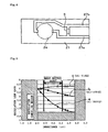
Fig. 5 is an explanatory view showing data for determining the inductance value of an inductor provided in the concentration sensor used in the above embodiment; and -
Fig. 6 is a block circuit diagram showing the concentration detector in the above embodiment. - Hereinafter, an embodiment of a concentration detector relating to the present invention will be explained. A whole structure of the concentration detector will be explained briefly first. The concentration detector is provided with a plurality of, for instance, 8 pieces of concentration sensors (quartz sensor) 1 and a measurement device
main unit 100 to which theseconcentration sensors 1 are detachably installed, as shown inFig. 1 . Theconcentration sensors 1 is provided with a circuit board, for instance, a printedcircuit board 21 as shown inFigs. 1 and2 , and an opening 23a is formed on the printedcircuit board 21. Arubber sheet 22 is overlaid on the front surface side of the above-described printedcircuit board 21, and arecess 23 is arranged on therubber sheet 22. The part corresponding to therecess 23 protrudes on the bottom surface side of therubber sheet 22, and its protruded part is fitted into the opening 23. Aquartz resonator 24 being a piezoelectric resonator is provided to cover the above-describedrecess 23. That is, one surface side (bottom surface side) of thequartz resonator 24 faces toward the above-describedopening 23, and the bottom surface side of thequartz resonator 24 is made to be an airtight space owing to the above-describedrecess 23, and thus, a Langevin-type concentration sensor is built up. - Furthermore, an
upper lid case 25 is installed from above therubber sheet 22. Theupper lid case 25 includes a pouring opening 25a for pouring a sample solution which is a fluid to be measured and an observation opening 25b for observing the sample solution. The sample solution is poured from the pouring opening 25a so that the sample solution is filled in a space on the upper surface side of the quartz resonator 24 (the quartz piece is immersed in the sample solution). - It should be noted that the structure of the
concentration sensor 1 may be such that thequartz resonator 24 is installed on the surface of the printedcircuit board 21 so as to cover the above-described opening 23a and the surroundings of thequartz resonator 24 is pressed with therubber sheet 22. - The
quartz resonator 24 includesrespective electrodes quartz piece 20, for instance, in a circular shape (theelectrode 24b on the back surface side is formed to be continuous to the peripheral part on the front surface side) as shown inFig. 3 , and theseelectrodes circuits substrate 21 via aconductive adhesive 26. An adsorbing layer (not shown) for adsorbing a sensing target is formed on one surface of thequartz resonator 24, for instance, on the front surface of theelectrode 24a. - Further as shown in
Figs. 2 to 4 , aninductor 3 composed of, for instance, discrete parts is connected between the printedcircuits inductor 3 is installed on thecircuit board 21 and covered with theupper lid case 25. Note that theinductor 3 may be formed using a print pattern. - A method of determining the inductance value of the
inductor 3 will be explained. Since the concentration sensor detects the concentration of a sensing substance in a fluid to be measured, for instance, in a solution to be measured, on the basis of the variation amount of oscillation frequency according to the mass of the sensing substance adhered to a peculiar adsorbing film, it must not stop oscillation in the fluid to be measured. However, according to an experiment, when thequartz piece 20 is immersed in a fluid sample, the equivalent series resistance R1 of thequartz piece 20 is drastically increased. For instance, in the case of driving thequartz piece 20 at 31MHz, it increases to as high as 500 Ω, though it is only 10 Ω when thequartz piece 20 is placed in the air, which means that it becomes a state to be extremely difficult for oscillation. - In order to solve this problem, the present invention intends to perform prevention of the stop oscillation by controlling the phase of the
quartz piece 20 by connecting theinductor 3 in parallel to thequartz piece 20. However, when the inductance value of theinductor 3 is set to a value to cancel the interelectrode capacitance C0, the following inconveniences take place. -
Fig. 5 is a relation diagram of inductance values and loop gains of theinductor 3 determined as such by calculation. The equivalent series resistance R1 of thequartz piece 3 is determined in these three settings of 6.8 Ω, 100 Ω, and 500 Ω. The reason for setting the equivalent series resistance R1 to these 3 values is to check how the relation between the inductance value and the oscillation loop gain varies using the equivalent series resistance R1 as a parameter, and to grasp the above-described relation under hard conditions in which a solution having the highest viscosity among the solutions measured with the concentration sensor is assumed and the equivalent series resistance R1 is estimated to be 500 Ω when thequartz piece 3 is immersed in the solution. In this example, since the resonance frequency Fr of thequartz piece 20 is 31MHz, the interelectrode capacitance C0 is 7.05pF, the inductance value with which the interelectrode capacitance C0 is cancelled at the series resonance point Fr of thequartz piece 20 is about 3.8µH. This inductance value is expressed to be 1/(C0 · ω2) where the angular velocity of the above-described resonance frequency Fr is ω. - When the equivalent series resistance R1 is 500 Ω, however, the inductance value of 3.8µH is not suitable because the oscillation loop gain is close to l. When setting an inductance value, since this inductance value is never exceeded, it is called Lmax (the largest value permissible) here.
- On the other hand, when the inductance value is made smaller for any equivalent series resistance R1, it stops oscillation because it loses the ability to cancel the effect of the interelectrode capacitance C0. The limit value thereof is about 2.0µH. The method of determining this limit value 2.0µH will be described here. The conditions to activate an oscillation circuit are such that when a signal goes once through around the circuit to be an intended oscillation loop, the gain should be one or more, and the phase should be an integral multiple of 360 degrees. The minimum of the inductance value satisfying the latter condition, i.e. phase condition is 2.0µH.
- A concrete example of the method of determining these conditions will be described as follows. The intended oscillation loop is cut at a point to form contact points A and B. Then, a signal source of the small signal so small as to make the circuit operate linearly is connected to the contact point A so as to drive the circuit. At this time, the signal at the contact point B is observed, and the ratio of the signals at the contact points A and B is taken. Then, the gain and phase at the time of making a circuit go once through around the oscillation loop are measured. Accordingly, it is possible to obtain the minimum inductance value at which the phase condition cannot be satisfied anymore when the inductance value of the inductor is varied. Then, when the gains are plotted using inductance values of the inductor connected in parallel to the quartz resonator as a parameter, the result shown in
Fig. 5 is obtained. - The above-described inductance value 2.0µH is the inductance value Lmin evaluated to be the minimum inductance value possible to oscillate in a state that the
quartz piece 20 is immersed in a fluid to be measured. As is clear fromFig. 5 , it is not appropriate for the concentration sensor to determine the above-described inductance value to Lmax with which the interelectrode capacitance C0 is cancelled. On the contrary, it is suitable to determine the value not too close to the oscillation canceling region but the value with which a sufficient oscillation loop gain can be obtained from the relation of the inductance values and oscillation loop gains between the inductance values Lmin and Lmax when immersing thequartz piece 20 in the measuring fluid. In this example, the range from 2.3µH to 3.5µH, which is ±20% around the mean value 2.9µH between the inductance values Lmin and Lmax is handled as the best suited range of the inductance value of theinductor 3. When the inductance value is determined in this way, the characteristics of the product is stabilized in mass production of the concentration sensor. - Since the greater the magnitude of the equivalent series resistance R1, the more the degree of lowering of the oscillation loop gain accompanying increase in the inductance value of the
inductor 3, the inductance values Lmin and Lmax are determined for the equivalent series resistance R1 at the time when the viscosity is highest among the fluids to be measured in which the concentration sensor is used, for instance, if the sensor is a gas-liquid dual purpose sensor, at the time when the viscosity is highest among the solutions to be measured, and the most suitable value for the inductance of theinductor 3 may be determined based on the relation between the inductance value and the oscillation loop gain during thereof. - Next, the circuit inside the measurement device
main unit 100 will be briefly explained usingFig. 6 . InFig. 6 ,4 designates an oscillation circuit to oscillate thequartz resonator 24 of theconcentration sensor 1, and ameasurement unit 6 is connected to the latter part of the oscillation circuit 4 via abuffer amplifier 5. The oscillation circuit 4 is structured as a Colpitts type oscillation circuit, Tr is a transistor used as an oscillation amplification device, 40 and 41 are capacitors constituting split capacitive elements, and Vc designates a supply source. As for other parts, 42 to 44 are capacitors, 45 to 48 are resistors. 49 designates a terminal unit which theconcentration sensor 1 is detachably connected to, provided in the measurement devicemain unit 100 shown inFig. 1 . - The
measurement unit 6 includes a measurement device to determine the signal relating to the frequency of the oscillation output of the oscillation circuit 4 such as a frequency counter, and a microprocessing unit for computing the variation in the count number. - It should be noted that this example takes an eight-channel structure having 8 pieces of the
concentration sensor 1 attached thereto, in which the circuit shown inFig. 6 is provided with 8 channels, and the output of each channel is switched over to be connected to themeasurement unit 6. - Operation of this embodiment will be explained next. First, the concentration sensor 1 (refer to
Fig. 1 ) is plugged into the measurement devicemain unit 100, a solution not containing a sensing target is filled in theconcentration sensor 1 and thequartz resonator 24 is oscillated to determine, for example, a blank value. The solution may be pure water or other solutions. The oscillation output in theoscillation circuit 3 is inputted into the measuringunit 6 via thebuffer amplifier 5, and for instance, the frequency of an oscillation output is measured. Then, a solution to be measured which is a sample to conduct detection of a sensing target is poured into theconcentration sensor 1, the variation of the oscillation frequency caused by pouring the measuring solution is measured by the measuringunit 6, and the concentration of the sensing target is detected based on the variation from, for instance, a calibration curve prepared in advance. - According to the above-described embodiment, the
inductor 3 is connected in parallel to thequartz piece 20, the value Lmin which is evaluated as the minimum value among the inductance values, at which thequartz piece 20 can be oscillated in a state of being immersed in a measuring solution, and the value Lmax canceling the interelectrode capacitance C0 are determined, an inductance value is suitably determined between the values Lmin and Lmax, considering the relation between the inductance value and the oscillation loop gain. Therefore, it is possible to reduce consumption of the oscillation energy due to the interelectrode capacitance C0 and it never stops oscillation even when various measuring fluids different in viscosity are used. In addition, since theconcentration sensor 1 attachable to and detachable from the measurement device main unit is provided with theinductor 3, it is possible to conduct suitable measurement by using theconcentration sensor 1 provided with theinductor 3 matching to the viscosity of a sample fluid. Accordingly, since no adjustment is required on the oscillation circuit 4 side for various concentration sensors, in other words, though it is a common oscillation circuit 4, it is applicable to the various concentration sensors. Therefore, it is not necessary to perform the complicated and time-consuming work of adjusting the oscillation circuit on the user side. - Further, when using the above-described
concentration sensor 1, since theconcentration sensor 1 can be replaced by detaching and attaching the printedcircuit 21 from and to the measurement devicemain unit 100, replacement work is easy. In addition, since a Langevin-type concentration sensor is structured by forming an airtight space on the bottom surface side of thequartz resonator 24 utilizing the opening 23a prepared in the printedcircuit 21, the structure to form the above-described airtight space is simple. - Note that the concentration sensor of the present invention is not limited to determination of the concentration of the sensing target, but it also includes a sensor for detecting the presence or absence of the sensing target.
Claims (5)
- A concentration sensor detachably connected to a measurement device main unit provided with an oscillation circuit to detect the concentration of a sensing target, comprising:a piezoelectric resonator including a piezoelectric piece having an adsorbing layer to adsorb a sensing target and varying the natural frequency thereof by adsorption of the sensing target, and electrodes respectively provided on both surfaces of the piezoelectric piece; andan inductor connected in parallel to said piezoelectric resonator.
- A concentration sensor, detachably connected to a measurement device main unit provided with an oscillation circuit to detect the concentration of a sensing target, comprising:a circuit board detachably connected to said measurement device main unit, and provided with a pair of conductive paths, the one end thereof serving as a terminal connected to the terminal of the measurement device main unit;a piezoelectric resonator provided on said circuit board, including a piezoelectric piece having an adsorbing layer for adsorbing a sensing target, varying the natural frequency by adsorption of the sensing target and electrodes respectively provided to both surfaces of the piezoelectric piece;an upper lid case forming a housing space for a fluid between said piezoelectric resonator and provided with a pouring opening for the fluid connecting through the housing space; andan inductor connected in parallel to said piezoelectric resonator, and provided between a pair of conductive paths of said circuit board.
- The concentration sensor according to claim 1, wherein the inductance value of said inductor is set to be ± 20% to the median value which is the mean value between the inductance value canceling the interelectrode capacitance of the piezoelectric resonator by a resonance frequency of said piezoelectric resonator and the minimum value of the inductance able to oscillate the piezoelectric resonator when immersed in the fluid to be measured.
- The concentration sensor according to claim 1, wherein said circuit board is provided with an opening, and the bottom side of said piezoelectric resonator faces a recess formed on said opening.
- A concentration detector, comprising:the concentration sensor according to any one of claim 1 to claim 4;a terminal unit to which the concentration sensor is detachably connected; anda measuring unit for determining the concentration of a sensing target based on the oscillation circuit for oscillating said piezoelectric resonator and the oscillation output from the oscillation circuit.
Applications Claiming Priority (2)
| Application Number | Priority Date | Filing Date | Title |
|---|---|---|---|
| JP2005225699 | 2005-08-03 | ||
| PCT/JP2006/315692 WO2007015575A1 (en) | 2005-08-03 | 2006-08-02 | Concentration sensor and concentration detection device |
Publications (1)
| Publication Number | Publication Date |
|---|---|
| EP1912053A1 true EP1912053A1 (en) | 2008-04-16 |
Family
ID=37708846
Family Applications (1)
| Application Number | Title | Priority Date | Filing Date |
|---|---|---|---|
| EP06768431A Withdrawn EP1912053A1 (en) | 2005-08-03 | 2006-08-02 | Concentration sensor and concentration detection device |
Country Status (5)
| Country | Link |
|---|---|
| US (1) | US7845230B2 (en) |
| EP (1) | EP1912053A1 (en) |
| CN (1) | CN101238361B (en) |
| TW (1) | TWI436063B (en) |
| WO (1) | WO2007015575A1 (en) |
Families Citing this family (5)
| Publication number | Priority date | Publication date | Assignee | Title |
|---|---|---|---|---|
| JP4960171B2 (en) * | 2007-08-08 | 2012-06-27 | 日本電波工業株式会社 | Sensing device |
| US8409875B2 (en) | 2010-10-20 | 2013-04-02 | Rapid Diagnostek, Inc. | Measurement of binding kinetics with a resonating sensor |
| JP6175434B2 (en) * | 2012-06-25 | 2017-08-02 | セイコーインスツル株式会社 | Piezoelectric unit, piezoelectric device, piezoelectric determination device, and state determination method |
| US11913906B2 (en) * | 2018-09-27 | 2024-02-27 | I-Pex Inc. | Substance detection device with improved efficiency |
| DE102020200771B4 (en) * | 2020-01-23 | 2023-03-30 | Vitesco Technologies Germany Gmbh | Fluid sensor device for detecting the filling level and/or the quality of a fluid and method for producing the same |
Family Cites Families (42)
| Publication number | Priority date | Publication date | Assignee | Title |
|---|---|---|---|---|
| JPS6185920A (en) | 1984-10-03 | 1986-05-01 | 株式会社 ニデツク | Apparatus for measuring cornea shape |
| JPS6185920U (en) | 1984-11-08 | 1986-06-05 | ||
| US5196347A (en) | 1986-07-03 | 1993-03-23 | Terumo Kabushiki Kaisha | Method for measuring oxygen concentration |
| JP2669848B2 (en) | 1988-03-25 | 1997-10-29 | 豊栄 森泉 | Chemical sensor for odor detection |
| US4991283A (en) | 1989-11-27 | 1991-02-12 | Johnson Gary W | Sensor elements in multilayer ceramic tape structures |
| JPH03257346A (en) | 1990-03-08 | 1991-11-15 | Seiko Instr Inc | Apparatus for measuring reaction |
| JP3041361B2 (en) | 1990-04-17 | 2000-05-15 | セイコーインスツルメンツ株式会社 | Reaction measurement device |
| JPH049744A (en) | 1990-04-27 | 1992-01-14 | Seiko Instr Inc | Quartz vibrator cell |
| JP2555002B2 (en) | 1991-06-27 | 1996-11-20 | 株式会社イナックス | Continuous quantitative analysis method of urinary components by flow injection method |
| DE4334834A1 (en) | 1993-10-13 | 1995-04-20 | Andrzej Dr Ing Grzegorzewski | Biosensor for measuring changes in viscosity and / or density |
| JP3499277B2 (en) | 1993-12-27 | 2004-02-23 | 東京電波株式会社 | Odor substance sensor and odor measurement device |
| US5744902A (en) * | 1995-05-16 | 1998-04-28 | The United States Of America As Represented By The Secretary Of The Army | Chemical and biological sensor based on microresonators |
| JP3257346B2 (en) | 1995-06-23 | 2002-02-18 | 市光工業株式会社 | Vehicle lamp with prism lens |
| JP2748246B2 (en) | 1995-11-14 | 1998-05-06 | デベロップメント センター フォー バイオテクノロジー | Cartridge-shaped piezoelectric sensor chip |
| JPH09250936A (en) | 1996-01-10 | 1997-09-22 | Ngk Insulators Ltd | Ceramic base body with surrounding circumferential space |
| JP3343030B2 (en) | 1996-05-22 | 2002-11-11 | 日本碍子株式会社 | Sensor element |
| JPH10142134A (en) | 1996-11-06 | 1998-05-29 | Yokogawa Electric Corp | Odor measuring apparatus |
| JPH10332463A (en) | 1997-03-31 | 1998-12-18 | Nippon Paint Co Ltd | Coating-film evaluating device using crystal oscillator and evaluation of coating-film expendability |
| JPH11183479A (en) | 1997-10-16 | 1999-07-09 | Fuji Electric Co Ltd | Sensor for measuring solution and method for measuring solution component |
| US6321588B1 (en) | 1998-09-11 | 2001-11-27 | Femtometrics, Inc. | Chemical sensor array |
| JP2000338022A (en) | 1999-05-25 | 2000-12-08 | Hokuto Denko Kk | Multi-channel qcm sensor device and multi-channel qcm measuring system |
| JP3643521B2 (en) | 1999-07-29 | 2005-04-27 | 株式会社日立製作所 | Corrosion environment monitoring device |
| DE19936693A1 (en) | 1999-08-04 | 2001-02-08 | Lre Technology Partner Gmbh | Instrument for the measurement of blood sugar concentrations has a test field with electrodes for the test strip and a circuit for measurement/evaluation of the current strength for display |
| JP2001083154A (en) | 1999-09-13 | 2001-03-30 | Agency Of Ind Science & Technol | Disease marker substance simplified compact detection device |
| DE29918177U1 (en) | 1999-10-14 | 2000-01-05 | Kan Chin Mao | Chassis for wire connection in two levels |
| JP2001201436A (en) | 2000-01-18 | 2001-07-27 | Shimadzu Corp | Gas-measuring apparatus |
| JP4794112B2 (en) | 2000-08-08 | 2011-10-19 | アレル・スウイツツアーランド・ゲゼルシヤフト・ミツト・ベシユレンクテル・ハフツング | Quartz crystal microbalance |
| JP2002148295A (en) | 2000-11-10 | 2002-05-22 | Ulvac Japan Ltd | Method and instrument for frequency measurement and analytical equipment |
| JP4387603B2 (en) | 2001-02-16 | 2009-12-16 | 株式会社アルバック | Measuring apparatus and measuring method |
| DE10203475A1 (en) | 2002-01-18 | 2003-07-31 | Bosch Gmbh Robert | Device for measuring viscosity and / or density |
| SE0203772D0 (en) | 2002-12-19 | 2002-12-19 | Attana Ab | Piezoelectric sensor arrangement |
| JP2004205392A (en) | 2002-12-26 | 2004-07-22 | Japan Science & Technology Agency | Qcm device and sample measuring method |
| JP3876842B2 (en) | 2003-03-04 | 2007-02-07 | セイコーエプソン株式会社 | Mass measuring chip and mass measuring device |
| JP2004304766A (en) * | 2003-03-17 | 2004-10-28 | Seiko Epson Corp | Oscillation circuit, adjustment method therefor, and mass measurement apparatus using the same |
| US20050052813A1 (en) | 2003-03-25 | 2005-03-10 | Yoshihiro Kobayashi | Mass measurement method, circuit for exciting piezoelectric vibration reed for mass measurement, and mass measurement apparatus |
| JP4213061B2 (en) | 2003-03-28 | 2009-01-21 | シチズンホールディングス株式会社 | QCM sensor and QCM sensor device |
| JP2005043123A (en) | 2003-07-24 | 2005-02-17 | Seiko Epson Corp | Liquid drop weight measuring instrument, and liquid drop delivery device |
| US7677087B2 (en) | 2004-12-15 | 2010-03-16 | Nihon Dempa Kogyo Co., Ltd. | Quartz sensor and sensing device |
| US7554247B2 (en) | 2004-12-15 | 2009-06-30 | Nihon Dempa Kogyo Co., Ltd | Component measuring device |
| EP1830169B1 (en) | 2004-12-15 | 2014-02-12 | Nihon Dempa Kogyo Co., Ltd. | Quartz sensor and sensing device |
| JP4134025B2 (en) | 2004-12-28 | 2008-08-13 | 日本電波工業株式会社 | Sensing device |
| US7300631B2 (en) * | 2005-05-02 | 2007-11-27 | Bioscale, Inc. | Method and apparatus for detection of analyte using a flexural plate wave device and magnetic particles |
-
2006
- 2006-08-02 WO PCT/JP2006/315692 patent/WO2007015575A1/en active Application Filing
- 2006-08-02 TW TW095128274A patent/TWI436063B/en not_active IP Right Cessation
- 2006-08-02 CN CN2006800287043A patent/CN101238361B/en not_active Expired - Fee Related
- 2006-08-02 EP EP06768431A patent/EP1912053A1/en not_active Withdrawn
- 2006-08-02 US US11/989,884 patent/US7845230B2/en not_active Expired - Fee Related
Non-Patent Citations (1)
| Title |
|---|
| See references of WO2007015575A1 * |
Also Published As
| Publication number | Publication date |
|---|---|
| WO2007015575A1 (en) | 2007-02-08 |
| CN101238361A (en) | 2008-08-06 |
| CN101238361B (en) | 2011-08-03 |
| TW200714900A (en) | 2007-04-16 |
| TWI436063B (en) | 2014-05-01 |
| US20100095750A1 (en) | 2010-04-22 |
| US7845230B2 (en) | 2010-12-07 |
Similar Documents
| Publication | Publication Date | Title |
|---|---|---|
| US7845230B2 (en) | Concentration sensor and concentration detector | |
| JP5066551B2 (en) | Piezoelectric sensor and sensing device | |
| US20130276533A1 (en) | Device for measuring fluid level in a container | |
| US7677087B2 (en) | Quartz sensor and sensing device | |
| US7552639B2 (en) | Quartz sensor and sensing device | |
| WO2003102218A3 (en) | Hybrid microcantilever sensors | |
| WO2008026764A1 (en) | Piezoelectric sensor and sensing device | |
| US8434351B2 (en) | Sensing instrument | |
| JP4542172B2 (en) | Sensing device and sensing method | |
| US20100329932A1 (en) | Sensing device | |
| JP4256871B2 (en) | Quartz sensor and sensing device | |
| JP6088857B2 (en) | Sensing sensor | |
| JP5826557B2 (en) | Sensing device and sensing method | |
| JP4369452B2 (en) | Concentration sensor and concentration detection device. | |
| JP4646813B2 (en) | Biosensor measurement system, viscosity measurement method, and trace mass measurement method | |
| JP4412546B2 (en) | Trace mass sensor chip, trace mass analysis system, and trace mass sensor chip analysis method | |
| JP5240794B2 (en) | Sensing device | |
| JP3146069B2 (en) | Concentration sensor | |
| JP6180198B2 (en) | Sensing sensor | |
| CN113758823A (en) | Integrated type pollutant measurement quartz crystal microbalance | |
| Zhang et al. | Design and evaluation of a dual channel high frequency Quartz crystal Microbalance | |
| JP4960171B2 (en) | Sensing device | |
| JP2013024648A (en) | Detection device and detection method | |
| JP3954430B2 (en) | Concentration measurement method | |
| JP2007064970A5 (en) |
Legal Events
| Date | Code | Title | Description |
|---|---|---|---|
| PUAI | Public reference made under article 153(3) epc to a published international application that has entered the european phase |
Free format text: ORIGINAL CODE: 0009012 |
|
| 17P | Request for examination filed |
Effective date: 20080201 |
|
| AK | Designated contracting states |
Kind code of ref document: A1 Designated state(s): AT BE BG CH CY CZ DE DK EE ES FI FR GB GR HU IE IS IT LI LT LU LV MC NL PL PT RO SE SI SK TR |
|
| STAA | Information on the status of an ep patent application or granted ep patent |
Free format text: STATUS: THE APPLICATION HAS BEEN WITHDRAWN |
|
| 18W | Application withdrawn |
Effective date: 20090709 |