JP4369452B2 - Concentration sensor and concentration detection device. - Google Patents
Concentration sensor and concentration detection device. Download PDFInfo
- Publication number
- JP4369452B2 JP4369452B2 JP2006210801A JP2006210801A JP4369452B2 JP 4369452 B2 JP4369452 B2 JP 4369452B2 JP 2006210801 A JP2006210801 A JP 2006210801A JP 2006210801 A JP2006210801 A JP 2006210801A JP 4369452 B2 JP4369452 B2 JP 4369452B2
- Authority
- JP
- Japan
- Prior art keywords
- piezoelectric vibrator
- concentration
- value
- wiring
- concentration sensor
- Prior art date
- Legal status (The legal status is an assumption and is not a legal conclusion. Google has not performed a legal analysis and makes no representation as to the accuracy of the status listed.)
- Expired - Fee Related
Links
Images


Landscapes
- Investigating Or Analyzing Materials By The Use Of Electric Means (AREA)
- Oscillators With Electromechanical Resonators (AREA)
Description
本発明は、感知対象物を吸着するための吸着層がその表面に形成され、感知対象物の吸着により固有振動数が変わる圧電片例えば水晶片を用い、この圧電片の固有振動数の変化分を検出して感知対象物の濃度を検出する装置の技術分野に関する。 The present invention uses a piezoelectric piece, for example, a quartz piece, in which an adsorption layer for adsorbing a sensing object is formed on its surface, and its natural frequency changes due to the adsorption of the sensing object. The present invention relates to a technical field of an apparatus for detecting the concentration of a sensing object by detecting the above.
微量な物質を感知する手法として水晶振動子を用いた濃度検出装置が知られている。この濃度検出装置は、水晶振動子の表面に感知対象物を吸着するための吸着層を形成して水晶センサー(濃度センサー)を構成し、感知対象物が吸着層に付着するとその固有振動数がその付着量に応じて変化することを利用して感知対象物の濃度を測定するものであり、より具体的には、水晶センサーに発振回路を接続すると共に発振回路の発振周波数を計測する測定部を設けて主要部が構成される。このような手法によれば、その応用範囲が広く、装置としても簡易な構成である上、感度が高いことから極微量な物質でも測定できるといった利点がある。 As a technique for sensing a very small amount of substance, a concentration detection device using a crystal resonator is known. In this concentration detection device, an adsorption layer for adsorbing a sensing object is formed on the surface of a quartz oscillator to constitute a quartz sensor (concentration sensor). When the sensing object adheres to the adsorption layer, its natural frequency is increased. A measurement unit that measures the concentration of a sensing object by utilizing the change in accordance with the amount of adhesion, and more specifically, a measurement unit that connects an oscillation circuit to a crystal sensor and measures the oscillation frequency of the oscillation circuit The main part is configured. According to such a technique, there are advantages that the application range is wide, the apparatus is simple in configuration, and the sensitivity is high, so even a very small amount of substance can be measured.
例えば特許文献1では、血液、尿などに含まれる疫病マーカ物質の分析を行うにあたって、水晶センサーを用いれば、高価で大型の自動分析装置を必要とする免疫ラテックスキットに代わる有効な手法であることが記載されている。このように水晶センサーをバイオセンサーとして用いる場合には、水晶振動子に感知対象物質に対して抗体抗原反応を起こす抗体からなる吸着層が形成される。
For example, in
ところで水晶センサーが液体中に浸漬されると、水晶片の等価直列抵抗の値が例えば数百Ωのレベルで増加し、例えば純水であれば150Ω程度増加する。このため水晶片に大きなエネルギーを与えるように設計されるが、水晶振動子の電極間容量C0がこのエネルギーを消費してエネルギーロスになってしまう。このため発振回路側にて電極間容量C0をキャンセルさせる必要があるが、ある水晶センサーについて発振回路側にてインダクタにより電極間容量C0をキャンセルさせていても、電極間容量C0の異なる水晶センサーに交換する場合には、発振回路側においてインダクタのインダクタンス値をその都度調整する必要がある。この操作は、ユーザ側で水晶センサーの種別毎に電極間容量C0をLCRメータなどで測定し、その測定値に基づいて計算した上で該当するインダクタンス値を有するインダクタと交換するという、煩雑で時間のかかる作業を強いられることになる。またインダクタを交換する代わりに、使用する水晶センサーの種別に対応して発振回路を用意しておくことも考えられるが、その場合には高価なシステムになってしまう。
なお特許文献2には、水晶振動子に並列にインダクタンスを接続して電極間容量を打ち消す必要があることが記載されているが、技術分野が全く異なる上、本発明の課題を解決できるものでもない。
By the way, when the quartz sensor is immersed in the liquid, the value of the equivalent series resistance of the quartz piece increases at a level of, for example, several hundreds Ω, and increases, for example, by about 150 Ω for pure water. For this reason, it is designed to give a large amount of energy to the crystal piece, but the interelectrode capacitance C0 of the crystal resonator consumes this energy, resulting in energy loss. For this reason, it is necessary to cancel the interelectrode capacitance C0 on the oscillation circuit side. However, even if a certain crystal sensor has the interelectrode capacitance C0 canceled by an inductor on the oscillation circuit side, a crystal sensor having a different interelectrode capacitance C0 is used. When replacing, it is necessary to adjust the inductance value of the inductor on the oscillation circuit side. This operation is complicated and time consuming, in which the user measures the interelectrode capacitance C0 with an LCR meter or the like for each type of quartz sensor, calculates the measured value based on the measured value, and replaces the inductor with a corresponding inductance value. Will be forced to work. Instead of exchanging the inductor, it may be possible to prepare an oscillation circuit corresponding to the type of crystal sensor to be used, but in this case, an expensive system is required.
本発明はこのような事情の下になされたものであり、感知対象物の吸着により固有振動数が変わる圧電片を用いた濃度センサー及びこれを使用した濃度検出装置において、共通の発振回路を用いながら複数の種別の濃度センサーに対応することができる技術を提供することにある。 The present invention has been made under such circumstances, and a common oscillation circuit is used in a concentration sensor using a piezoelectric piece whose natural frequency changes due to adsorption of a sensing object and a concentration detection device using the same. However, it is to provide a technique capable of dealing with a plurality of types of density sensors.
本発明は、発振回路を備えると共に試料液の外に置かれる測定器本体に着脱自在に接続され、感知対象物の濃度を検出するための濃度センサーにおいて、
配線が形成された配線基板と、
圧電片と、この圧電片の一面側及び他面側に各々設けられかつ前記配線に接続された電極と、前記一面側の電極の表面に設けられ、試料液中の感知対象物を吸着するため吸着層と、を含み、感知対象物の吸着により固有振動数が変わる圧電振動子と、
前記圧電片が前記配線基板上に当該基板と並行に設けられかつ前記他面側の電極が、試料液が位置する領域から区画された空間に臨むように設けられたことと、
前記圧電振動子に対して並列に接続されるように、前記配線基板上の配線間に設けられ、圧電振動子が試料液中に置かれたときに前記電極間容量による発振エネルギーの消費を抑えるためのインダクタと、
前記配線基板に設けられ、前記圧電振動子の電極に前記配線を介して電気的に接続され、測定器本体に対して前記配線基板を差し込むことにより測定器本体側の端子に接続されるように構成された端子部と、を備えたことを特徴とする。
前記圧電振動子との間に流体の収容空間を形成し、この収容空間に連通する流体注入口を有する上蓋ケースを設けるようにしてもよい。
前記圧電振動子に対して並列に接続され、前記配線基板の一対の導電路の間に設けられたインダクタと、を備えたことを特徴とする濃度センサーである。
The present invention is detachably connected to the instrument body to be placed outside the Rutotomoni sample solution comprising an oscillating circuit, at a concentration sensor for detecting the concentration of the sensing target,
A wiring board on which wiring is formed; and
A piezoelectric piece, an electrode provided on one side and the other side of the piezoelectric piece and connected to the wiring, and provided on the surface of the electrode on the one side, for adsorbing the sensing object in the sample liquid A piezoelectric vibrator including an adsorption layer, the natural frequency of which changes due to adsorption of the sensing object;
The piezoelectric piece is provided on the wiring substrate in parallel with the substrate, and the electrode on the other surface is provided so as to face a space partitioned from a region where the sample liquid is located;
Provided between the wirings on the wiring board so as to be connected in parallel to the piezoelectric vibrator, and suppresses the consumption of oscillation energy due to the interelectrode capacitance when the piezoelectric vibrator is placed in the sample liquid. An inductor for
Provided on the wiring board, electrically connected to the electrodes of the piezoelectric vibrator via the wiring, and connected to a terminal on the measuring instrument main body by inserting the wiring board into the measuring instrument main body. And a configured terminal portion .
Wherein forming a housing space for a fluid between the piezoelectric vibrator may be provided upper cover case having a fluid inlet communicating with the receiving space.
A concentration sensor comprising: an inductor connected in parallel to the piezoelectric vibrator and provided between a pair of conductive paths of the wiring board.
前記インダクタのインダクタンス値は、前記圧電振動子の共振周波数にて当該圧電振動子の電極間容量をキャンセルするインダクタンス値と圧電振動子を被測定流体中に浸漬した状態で発振可能なインダクタンス値の最小値との平均値を中心値とし、この中心値に対して±20%の値に設定されていることが好ましい。
また前記配線基板には開口部が設けられ、前記圧電振動子は、前記開口部側に形成された凹部に下面側が面している構造を採用することが好ましい。
本発明の濃度センサーは、例えば圧電片として水晶片を用いたランジュバン型の水晶センサーとして構成され、基板上に水晶振動子を装着すると共に水晶振動子の電極に例えば導電性接着剤を介して基板上の導電路をなすプリント配線を接続し、プリント配線間にインダクタを接続して構成される。
The inductance value of the inductor is the minimum of the inductance value that cancels the interelectrode capacitance of the piezoelectric vibrator at the resonance frequency of the piezoelectric vibrator and the inductance value that can oscillate when the piezoelectric vibrator is immersed in the fluid to be measured. It is preferable that an average value with respect to the value is set as a central value, and is set to a value of ± 20% with respect to the central value.
The wiring board is preferably provided with an opening, and the piezoelectric vibrator preferably has a structure in which a lower surface faces a recess formed on the opening.
The concentration sensor of the present invention is configured, for example, as a Langevin type crystal sensor using a crystal piece as a piezoelectric piece, and a crystal resonator is mounted on the substrate and the electrode of the crystal resonator is connected to the substrate via, for example, a conductive adhesive It is configured by connecting the printed wiring forming the upper conductive path and connecting the inductor between the printed wiring.
また本発明の濃度検出装置は、上記の濃度センサーと、この濃度センサーの着脱端子、前記圧電片を発振させるための発振回路及び発振回路からの発振出力に基づいて感知対象物の濃度を検出する測定部と、を備えたことを特徴とする。 The concentration detection apparatus of the present invention detects the concentration of the sensing object based on the above-described concentration sensor, a detachable terminal of the concentration sensor, an oscillation circuit for oscillating the piezoelectric piece, and an oscillation output from the oscillation circuit. And a measuring unit.
本発明によれば、濃度センサーを構成する圧電片に対して並列にインダクタを接続しているため、そのインダクタンス値を適切な値に決定することにより、電極間容量による発振エネルギーの消費を抑えながら、粘性の異なる種々の被測定流体(試料流体)中にて発振停止することがない。そして濃度センサーにインダクタを設けていることから、種々の濃度センサーに対して発振回路側を調整しなくて済むので、即ち共通の発振回路でありながら種々の濃度センサーに対応することができるので、ユーザ側で発振回路側を調整するという煩雑で手間のかかる作業が不要になる。 According to the present invention, since the inductor is connected in parallel to the piezoelectric piece constituting the concentration sensor, the consumption of oscillation energy due to the capacitance between the electrodes is suppressed by determining the inductance value to be an appropriate value. The oscillation does not stop in various measured fluids (sample fluids) having different viscosities. And since the density sensor is provided with an inductor, it is not necessary to adjust the oscillation circuit side with respect to various density sensors, that is, it is possible to cope with various density sensors while being a common oscillation circuit. The troublesome and time-consuming work of adjusting the oscillation circuit side on the user side becomes unnecessary.
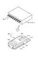
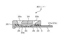
以下に本発明に係る濃度検出装置の実施の形態を説明する。先ず濃度検出装置の全体構造について簡単に説明しておく。この濃度検出装置は図1に示すように、複数例えば8個の濃度センサー(水晶センサー)1と、これら濃度センサー1が着脱自在に装着される測定器本体100とを備えている。濃度センサー1は、図1及び図2に示すように配線基板例えばプリント基板21を備えており、このプリント基板21には、開口部23aが形成されている。前記プリント基板21の表面側にはゴムシート22が重ねられ、このゴムシート22には、凹部23が設けられている。ゴムシート22の下面側において、この凹部23に対応する部位は突出しており、その突出部位は前記開口部23に嵌合している。そして前記凹部23を塞ぐように圧電振動子である水晶振動子24が設けられている。即ち、水晶振動子24の一面側(下面側)は前記開口部23側に向いていることになり、水晶振動子24の下面側は前記凹部23により気密空間とされ、これによってランジュバン型の濃度センサーが構成される。
Embodiments of the concentration detection apparatus according to the present invention will be described below. First, the overall structure of the concentration detection apparatus will be briefly described. As shown in FIG. 1, the concentration detection apparatus includes a plurality of, for example, eight concentration sensors (quartz sensors) 1 and a measuring instrument main body 100 to which these
更にゴムシート22の上から上蓋ケース25が装着されている。上蓋ケース25には、被測定流体である試料溶液を注入するための注入口25aと試料溶液の観察口25bとが形成され、注入口25aから試料溶液が注入され、水晶振動子24の上面側の空間に試料溶液が満たされることになる(水晶片が試料溶液に浸漬されることになる)。
なお、濃度センサー1の構造としては、水晶振動子24を、前記開口部23aを塞ぐようにプリント基板21の表面に載置するように設け、水晶振動子24の周縁部をゴムシート22により押さえつける構造であってもよい。
Further, an
The
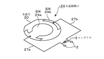
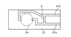
水晶振動子24は、図3に示すように例えば円形の水晶片20の両面に夫々電極24a、24b(裏面側の電極24bは表面側の周縁部に連続形成されている)が設けられ、これら電極24a、24bは導電性接着剤26を介して基板21に設けられている一対の導電路であるプリント配線27a、27bに夫々電気的に接続されている。また水晶振動子24の一面例えば電極24aの表面には、感知対象物を吸着するための吸着層(図示せず)が形成されている。
As shown in FIG. 3, the
更に図2〜図4に示すように、プリント配線27a、27b間には、例えば個別部品からなるインダクタ3が接続されており、このインダクタ3は配線基板21上に実装されて、上蓋ケース25により覆われている。なおインダクタ3は、プリントパターンにより形成されていてもよい。
このインダクタ3のインダクタンス値の決定方法について説明する。濃度センサーは、特殊な吸着膜に付着する感知物質の質量に応じた発振周波数の変化量に基づいて、被測定流体例えば被測定溶液中の感知物質の濃度を検出するものであるから、被測定流体中において発振停止してはならない。しかしながら実験によれば、水晶片20を液体試料中に浸漬すると、水晶片20の等価直列抵抗R1が飛躍的に増大し、31MHzで水晶片20を駆動させる場合を例にとると、水晶片20を気体中に置いたときには10Ωであるのに対して500Ωにもなり、非常に発振しにくい状態となる。
Further, as shown in FIGS. 2 to 4, an
A method for determining the inductance value of the
これを打開するために、本発明では水晶片20に対して並列にインダクタ3を接続し、水晶片20の位相をコントロールして発振防止を図ろうとしている。しかしインダクタ3のインダクタンス値を電極間容量C0をキャンセルする値に設定すると次ぎのような不具合が生じる。
図5は、インダクタ3のインダクタンス値とループゲインとの関係を計算により求めた関係図である。ここでは水晶片3の等価直列抵抗R1を6.8Ω、100Ω及び500Ωの3通りに設定している。このように3通り設定した理由は、インダクタンス値と発振ループゲインとの関係が等価直列抵抗R1をパラメータとしてどのように変化するかを調べるためであり、また濃度センサーの被測定溶液の中で粘性が最も大きい溶液を想定し、その溶液に水晶片3を浸漬したときの等価直列抵抗R1を500Ωと見積もって、過酷条件下における上記関係を把握するためである。この例では、水晶片20の共振周波数Frが31MHz、電極間容量C0が7.05pFであるため、水晶片20の直列共振点Frにて電極間容量C0をキャンセルするインダクタンス値はおよそ3、8μHとなる。このインダクタンス値は、前記共振周波数Frの角速度をωとすると、1/(C0・ω2 )で表される。
In order to overcome this problem, the present invention attempts to prevent oscillation by connecting the
FIG. 5 is a relationship diagram in which the relationship between the inductance value of the
しかし、等価直列抵抗R1が500Ωである場合には、3、8μHという値は発振ループゲインが1に近付いていることから適切な値ではない。インダクタンス値を設定するときにこのインダクタンス値を越えることはあり得ないので、ここではこのインダクタンス値をLmax(設定限界の最大値)と称することにしている。 However, when the equivalent series resistance R1 is 500Ω, the value of 3 and 8 μH is not an appropriate value because the oscillation loop gain approaches 1. Since this inductance value cannot be exceeded when setting the inductance value, this inductance value is referred to herein as Lmax (maximum value of the setting limit).
一方、いずれの等価直列抵抗R1においても、インダクタンス値を小さくしていくと、電極間容量C0の影響を打ち消すことができなくなって発振しなくなり、その限界値はおよそ2.0μH程度である。ここでこの限界値である2.0μHを求める手法について述べる。発振回路の発振条件は、意図した発振ループとなる回路を信号が一巡したときにゲインが1以上であり、かつ位相が360度の整数倍になることである。後者の条件である位相条件を満足するインダクタンス値の最小値が2.0μHである。
これら条件の求め方について具体例を挙げると、意図した発振ループの一箇所を切断し、接点Aと接点Bとを形成する。そして回路が線形で動作する程度の小信号の信号源を接点Aに接続し、ドライブする。このとき接点Bの信号を観測し、接点Aと接点Bとにおける信号の比を取り、発振ループを一巡したときのゲインと位相とを調べる。従ってインダクタのインダクタンス値を変えていったときに、位相条件を満足しなくなるインダクタンス値の最小値を得ることができる。そして水晶振動子に並列に接続されるインダクタのインダクタンス値をパラメータとしてゲインをプロットすると、図5に示す結果が得られる。
On the other hand, in any equivalent series resistance R1, if the inductance value is decreased, the influence of the interelectrode capacitance C0 cannot be canceled and oscillation does not occur, and its limit value is about 2.0 μH. Here, a method for obtaining the limit value of 2.0 μH will be described. The oscillation condition of the oscillation circuit is that the gain is 1 or more and the phase is an integral multiple of 360 degrees when the signal goes around the circuit that becomes the intended oscillation loop. The minimum inductance value that satisfies the latter phase condition is 2.0 μH.
As a specific example of how to obtain these conditions, one point of the intended oscillation loop is cut to form the contact A and the contact B. Then, a signal source of a small signal that allows the circuit to operate linearly is connected to the contact A and driven. At this time, the signal at the contact B is observed, the ratio of the signals at the contact A and the contact B is taken, and the gain and phase when the oscillation loop is completed are examined. Accordingly, when the inductance value of the inductor is changed, a minimum inductance value that does not satisfy the phase condition can be obtained. Then, when the gain is plotted using the inductance value of the inductor connected in parallel to the crystal resonator as a parameter, the result shown in FIG. 5 is obtained.
上記のインダクタンス値2.0μHの値は、水晶片20を被測定流体中に浸漬した状態で発振可能なインダクタンス値の最小値であると評価したインダクタンス値Lminということになる。図5から分かるように、濃度センサーにおいては、前記インダクタンス値は、電極間容量C0をキャンセルするインダクタンス値Lmaxに設定することは適切ではなく、水晶片20を被測定液に浸漬した状態でのインダクタンス値LminとLmaxとの間におけるインダクタンス値と発振ループゲインとの関係から、発振停止領域に近すぎず、十分な発振ループゲインが得られる値に決定することが適切である。この例では、インダクタンス値LminとLmaxとの平均値2.9μHを中心として±20%の2.3μH〜3.5μHの範囲をインダクタ3のインダクタンス値の最適範囲として取り扱っている。このようにインダクタンス値を設定すれば、濃度センサーを量産する場合において、量産品の特性が安定する。
The value of the inductance value of 2.0 μH is the inductance value Lmin evaluated as the minimum value of the inductance value that can oscillate when the
ここで等価直列抵抗R1が大きくなるほど、インダクタ3のインダクタンス値の増大に伴う発振ループゲインの低下の程度が大きいことから、濃度センサーが使用される被測定流体の中で最も粘度が大きい流体、例えば気液両用の濃度センサーであれば、被測定液のなかで最も粘度が大きいときの等価直列抵抗R1について、インダクタンス値LminとLmaxとを求め、そしてその間におけるインダクタンス値と発振ループゲインとの関係に基づいてインダクタ3のインダクタンス値の適切な値を決定すればよいことになる。
Here, as the equivalent series resistance R1 increases, the degree of decrease in the oscillation loop gain accompanying the increase in the inductance value of the
続いて測定器本体100の内部回路について図6を用いて簡単に説明しておく。図6中、4は濃度センサー1の水晶振動子24を発振させるための発振回路であり、この発振回路4の後段には、バッファアンプ5を介して測定部6が接続されている。発振回路4はコルピッツ型発振回路として構成されており、Trは、発振増幅素子としてのトランジスタ、40、41は分割容量成分をなすコンデンサ、Vcは電源である。その他の部位については、42〜44はコンデンサ、45〜48は抵抗である。また49は濃度センサー1が着脱自在に接続される端子部であり、図1に示す測定器本体100に設けられている。
測定部6は、発振回路4の発振出力の周波数に関する信号を測定する例えば周波数カウンタ、そのカウント数の変化分を演算する演算部などを備えている。
なおこの例では濃度センサー1が8個取り付けられる8チャンネル構成になっていて、図6に示す回路が8チャンネル用意され、各チャンネルの出力が切り替えられて測定部6に接続される構成となっている。
Next, the internal circuit of the measuring instrument main body 100 will be briefly described with reference to FIG. In FIG. 6, reference numeral 4 denotes an oscillation circuit for oscillating the
The
In this example, eight
続いてこの実施の形態の作用について述べる。先ず濃度センサー1(図1参照)を測定器本体100に差込み、例えばブランク値を求めるために感知対象物が含まれない溶液を濃度センサー1内に満たし、水晶振動子24を発振させる。この溶液は純水であってもよいし、あるいはその他の溶液であってもよい。発振回路3における発振出力はバッファアンプ5を介して測定部6に入力され、例えば発振出力の周波数が測定される。次いで感知対象物の感知を行うために検体である被測定溶液を濃度センサー1に注入し、被測定溶液を入れたことによる発振周波数の変化分を測定部6により求め、例えば予め作成した検量線によりその変化分に基づいて感知対象物の濃度を検出する。
Next, the operation of this embodiment will be described. First, the concentration sensor 1 (see FIG. 1) is inserted into the measuring device main body 100, and for example, a solution containing no sensing object is filled in the
上述の実施の形態によれば、水晶片20に対して並列にインダクタ3を接続し、水晶片20を被測定溶液に浸漬した状態での発振可能なインダクタンス値の最小値であると評価した値Lminと電極間容量C0をキャンセルする値Lmaxとを求め、これらの間において、インダクタンス値と発振ループゲインとの関係を見据えた上でそのインダクタンス値を適切な値に決定しているため、電極間容量C0による発振エネルギーの消費を抑えることができ、また粘性の異なる種々の被測定流体に用いても発振停止することがない。そして測定器本体に着脱できる濃度センサー1にインダクタ3を設けていることから、試料流体の粘度に見合ったインダクタ3を備えた濃度センサー1を用いることにより、適切な測定を行うことができる。従って種々の濃度センサーに対して発振回路4側を調整しなくて済むので、即ち共通の発振回路4でありながら種々の濃度センサーに対応することができるので、ユーザ側で発振回路4側を調整するという煩雑で手間のかかる作業が不要になる。
更に上述の濃度センサー1によれば、測定器本体100に対してプリント基板21を着脱することにより濃度センサー1を交換できるので、交換作業が容易である。またプリント基板21に形成した開口部23aを利用して水晶振動子24の下面側に気密空間を形成してランジュバン型の濃度センサーを構成しているので、前記気密空間を形成する構造が簡単である。
According to the above-described embodiment, the
Furthermore, according to the above-described
なお本発明の濃度センサーは、感知対象物の濃度を求めることに限定されるものではなく、感知対象物の有無センサーも含むものとする。 The concentration sensor of the present invention is not limited to the determination of the concentration of the sensing object, and includes a presence / absence sensor of the sensing object.
1 濃度センサー
20 水晶片
24 水晶振動子
24a、24b 電極
27a、27b 導電路をなすプリント配線
3 インダクタ
4 発振回路
49 端子部
5 バッファアンプ
6 測定部
100 測定器本体
DESCRIPTION OF
Claims (5)
配線が形成された配線基板と、
圧電片と、この圧電片の一面側及び他面側に各々設けられかつ前記配線に接続された電極と、前記一面側の電極の表面に設けられ、試料液中の感知対象物を吸着するため吸着層と、を含み、感知対象物の吸着により固有振動数が変わる圧電振動子と、
前記圧電片が前記配線基板上に当該基板と並行に設けられかつ前記他面側の電極が、試料液が位置する領域から区画された空間に臨むように設けられたことと、
前記圧電振動子に対して並列に接続されるように、前記配線基板上の配線間に設けられ、圧電振動子が試料液中に置かれたときに前記電極間容量による発振エネルギーの消費を抑えるためのインダクタと、
前記配線基板に設けられ、前記圧電振動子の電極に前記配線を介して電気的に接続され、測定器本体に対して前記配線基板を差し込むことにより測定器本体側の端子に接続されるように構成された端子部と、を備えたことを特徴とする濃度センサー。 Is detachably connected to the measuring instrument body to be placed outside the Rutotomoni sample solution comprising an oscillating circuit, at a concentration sensor for detecting the concentration of the sensing target,
A wiring board on which wiring is formed; and
A piezoelectric piece, an electrode provided on one side and the other side of the piezoelectric piece and connected to the wiring, and provided on the surface of the electrode on the one side, for adsorbing the sensing object in the sample liquid A piezoelectric vibrator including an adsorption layer, the natural frequency of which changes due to adsorption of the sensing object;
The piezoelectric piece is provided on the wiring substrate in parallel with the substrate, and the electrode on the other surface is provided so as to face a space partitioned from a region where the sample liquid is located;
Provided between the wirings on the wiring board so as to be connected in parallel to the piezoelectric vibrator, and suppresses the consumption of oscillation energy due to the interelectrode capacitance when the piezoelectric vibrator is placed in the sample liquid. An inductor for
Provided on the wiring board, electrically connected to the electrodes of the piezoelectric vibrator via the wiring, and connected to a terminal on the measuring instrument main body by inserting the wiring board into the measuring instrument main body. A density sensor comprising: a configured terminal portion .
Priority Applications (1)
| Application Number | Priority Date | Filing Date | Title |
|---|---|---|---|
| JP2006210801A JP4369452B2 (en) | 2005-08-03 | 2006-08-02 | Concentration sensor and concentration detection device. |
Applications Claiming Priority (2)
| Application Number | Priority Date | Filing Date | Title |
|---|---|---|---|
| JP2005225699 | 2005-08-03 | ||
| JP2006210801A JP4369452B2 (en) | 2005-08-03 | 2006-08-02 | Concentration sensor and concentration detection device. |
Publications (3)
| Publication Number | Publication Date |
|---|---|
| JP2007064970A JP2007064970A (en) | 2007-03-15 |
| JP2007064970A5 JP2007064970A5 (en) | 2009-09-03 |
| JP4369452B2 true JP4369452B2 (en) | 2009-11-18 |
Family
ID=37927311
Family Applications (1)
| Application Number | Title | Priority Date | Filing Date |
|---|---|---|---|
| JP2006210801A Expired - Fee Related JP4369452B2 (en) | 2005-08-03 | 2006-08-02 | Concentration sensor and concentration detection device. |
Country Status (1)
| Country | Link |
|---|---|
| JP (1) | JP4369452B2 (en) |
Families Citing this family (2)
| Publication number | Priority date | Publication date | Assignee | Title |
|---|---|---|---|---|
| JP5066442B2 (en) * | 2007-12-28 | 2012-11-07 | 日本電波工業株式会社 | Piezoelectric sensor and sensing device |
| JP5051798B2 (en) * | 2010-06-30 | 2012-10-17 | 日本電波工業株式会社 | Sensing device |
-
2006
- 2006-08-02 JP JP2006210801A patent/JP4369452B2/en not_active Expired - Fee Related
Also Published As
| Publication number | Publication date |
|---|---|
| JP2007064970A (en) | 2007-03-15 |
Similar Documents
| Publication | Publication Date | Title |
|---|---|---|
| JP5066551B2 (en) | Piezoelectric sensor and sensing device | |
| US8434351B2 (en) | Sensing instrument | |
| JPH07190919A (en) | Biosensor for measuring at least one of viscosity and density | |
| US8802428B2 (en) | Method of detecting microorganisms and microorganism detecting apparatus | |
| TWI436063B (en) | Concentration sensor and concentration detection device | |
| JP4256871B2 (en) | Quartz sensor and sensing device | |
| JP4369452B2 (en) | Concentration sensor and concentration detection device. | |
| JP5826557B2 (en) | Sensing device and sensing method | |
| JP6088857B2 (en) | Sensing sensor | |
| JP4646813B2 (en) | Biosensor measurement system, viscosity measurement method, and trace mass measurement method | |
| EP2071316B1 (en) | Sensing device | |
| JP5708027B2 (en) | Sensing device | |
| ATE518120T1 (en) | MEASURING METHOD AND BIOSENSOR SYSTEM WITH RESONATOR | |
| JP6180198B2 (en) | Sensing sensor | |
| WO2020179894A1 (en) | Measurement device, measurement method, and computation device | |
| JP2009031233A (en) | Multi-channel qcm sensor | |
| JP4865002B2 (en) | Quartz sensor and sensing device | |
| US20170146490A1 (en) | Sensing sensor | |
| JP3954430B2 (en) | Concentration measurement method | |
| JP2013024648A (en) | Detection device and detection method | |
| JP2020094970A (en) | Sensing device and sensing method | |
| JPH03148040A (en) | Viscosity measuring apparatus | |
| JP2019168284A (en) | Sensing sensor | |
| JP2000088630A (en) | Method and equipment for measuring quantity of liquid |
Legal Events
| Date | Code | Title | Description |
|---|---|---|---|
| A621 | Written request for application examination |
Free format text: JAPANESE INTERMEDIATE CODE: A621 Effective date: 20090227 |
|
| A521 | Written amendment |
Free format text: JAPANESE INTERMEDIATE CODE: A523 Effective date: 20090717 |
|
| A871 | Explanation of circumstances concerning accelerated examination |
Free format text: JAPANESE INTERMEDIATE CODE: A871 Effective date: 20090717 |
|
| TRDD | Decision of grant or rejection written | ||
| A975 | Report on accelerated examination |
Free format text: JAPANESE INTERMEDIATE CODE: A971005 Effective date: 20090805 |
|
| A01 | Written decision to grant a patent or to grant a registration (utility model) |
Free format text: JAPANESE INTERMEDIATE CODE: A01 Effective date: 20090818 |
|
| A01 | Written decision to grant a patent or to grant a registration (utility model) |
Free format text: JAPANESE INTERMEDIATE CODE: A01 |
|
| A61 | First payment of annual fees (during grant procedure) |
Free format text: JAPANESE INTERMEDIATE CODE: A61 Effective date: 20090827 |
|
| R150 | Certificate of patent or registration of utility model |
Free format text: JAPANESE INTERMEDIATE CODE: R150 |
|
| FPAY | Renewal fee payment (event date is renewal date of database) |
Free format text: PAYMENT UNTIL: 20120904 Year of fee payment: 3 |
|
| FPAY | Renewal fee payment (event date is renewal date of database) |
Free format text: PAYMENT UNTIL: 20120904 Year of fee payment: 3 |
|
| FPAY | Renewal fee payment (event date is renewal date of database) |
Free format text: PAYMENT UNTIL: 20120904 Year of fee payment: 3 |
|
| FPAY | Renewal fee payment (event date is renewal date of database) |
Free format text: PAYMENT UNTIL: 20130904 Year of fee payment: 4 |
|
| R250 | Receipt of annual fees |
Free format text: JAPANESE INTERMEDIATE CODE: R250 |
|
| LAPS | Cancellation because of no payment of annual fees |