EP1815951B1 - Robot controller and robot system - Google Patents
Robot controller and robot system Download PDFInfo
- Publication number
- EP1815951B1 EP1815951B1 EP05805507A EP05805507A EP1815951B1 EP 1815951 B1 EP1815951 B1 EP 1815951B1 EP 05805507 A EP05805507 A EP 05805507A EP 05805507 A EP05805507 A EP 05805507A EP 1815951 B1 EP1815951 B1 EP 1815951B1
- Authority
- EP
- European Patent Office
- Prior art keywords
- robot
- program
- control apparatus
- robots
- task
- Prior art date
- Legal status (The legal status is an assumption and is not a legal conclusion. Google has not performed a legal analysis and makes no representation as to the accuracy of the status listed.)
- Expired - Fee Related
Links
Images


Classifications
-
- B—PERFORMING OPERATIONS; TRANSPORTING
- B25—HAND TOOLS; PORTABLE POWER-DRIVEN TOOLS; MANIPULATORS
- B25J—MANIPULATORS; CHAMBERS PROVIDED WITH MANIPULATION DEVICES
- B25J9/00—Programme-controlled manipulators
- B25J9/16—Programme controls
- B25J9/1656—Programme controls characterised by programming, planning systems for manipulators
- B25J9/1671—Programme controls characterised by programming, planning systems for manipulators characterised by simulation, either to verify existing program or to create and verify new program, CAD/CAM oriented, graphic oriented programming systems
-
- G—PHYSICS
- G05—CONTROLLING; REGULATING
- G05B—CONTROL OR REGULATING SYSTEMS IN GENERAL; FUNCTIONAL ELEMENTS OF SUCH SYSTEMS; MONITORING OR TESTING ARRANGEMENTS FOR SUCH SYSTEMS OR ELEMENTS
- G05B2219/00—Program-control systems
- G05B2219/30—Nc systems
- G05B2219/39—Robotics, robotics to robotics hand
- G05B2219/39117—Task distribution between involved manipulators
-
- G—PHYSICS
- G05—CONTROLLING; REGULATING
- G05B—CONTROL OR REGULATING SYSTEMS IN GENERAL; FUNCTIONAL ELEMENTS OF SUCH SYSTEMS; MONITORING OR TESTING ARRANGEMENTS FOR SUCH SYSTEMS OR ELEMENTS
- G05B2219/00—Program-control systems
- G05B2219/30—Nc systems
- G05B2219/40—Robotics, robotics mapping to robotics vision
- G05B2219/40392—Programming, visual robot programming language
Definitions
- the present invention relates to a robot control apparatus and a robot system thereof for controlling a plurality of robots.
- ORCCAD A programming environment for robotic systems, called ORCCAD is described in the article "the ORCCAD Architecture", International Journal of Robotics Research, Sage Science Press, Thousand Oaks, USA, Vol. 17, No. 4, pages 338-359, 1998, by J-J. Borrelly et al.
- the environment provides graphic based tools for programming robot actions in a complex architecture. Basic robot actions are combined into “robot-tasks", while robot-tasks are further logically composed into more complex “robot-procedures”.
- a sequence program shown in Fig. 7 As a program of a background art of a robot control apparatus for controlling a plurality of robots, there is a sequence program shown in Fig. 7 .
- a vertical column thereof is described with steps from step 1 through steps 2, 3...
- a horizontal column thereof is described with R1 item, R2 item and R3 item for respectively controlling robots RB1, RB2, and RB3.
- the same rows are the same steps and processed in parallel.
- a processing at each step is started after finishing to process one step before the each step.
- Each R item comprises F column, operation column, part column, tool column, location column.
- F column displays presence/absence of a process continued from a preceding step, and when F column is described with an arrow mark, as in, for example, F column of step 2 of R3 item, it shows that a process of step 1 one step before thereof is continued to process also at step 2 (refer to Patent Reference 1).
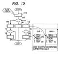
- a display region of a display screen of an operation program/state display portion is divided into a master task display region 71, a sub 1 task display region 72, a sub 2 task display region 73, a state display region 74, and a plurality of operation programs operated synchronizingly in accordance with a flowchart of Fig. 9 are displayed while cooperatively operating the operation programs as shown by Fig. 10.
- Fig. 10 shows the flowchart of Fig. 9 on a left side, shows a state display screen by respective operation programs of robots of Fig.
- Patent Reference 1 JP-A-6-67709 (page 3, right row, line 46 through page 4, left row, line 17, Fig. 2 )
- Patent Reference 2 JP-A-11-48178 (page 3, right row, line 33 through page 4, left row, line 3, Fig. 2, Fig. 3 , Fig. 6 )
- Patent Reference 1 The invention described in Patent Reference 1 is effective in that when parallel processings are executed for respective robots, programs can be formed for the respective robots.
- an operator cannot comprehensively determine whether processings are executed in parallel by a certain operation unit, or processings are carried out synchronizingly.
- the operation is constituted by a plurality of operation steps of a step of setting a work to a jig, a step of executing welding, a step of reversing the work, a step of executing welding, a step of carrying the work to a next step and the like.
- Patent Reference 1 poses a problem that the operator can determine by only viewing programs with regard to that in relation to the operation steps, which operation step is being executed currently, or under what condition, the execution transits from the operation step to a next step or the like.
- the invention is for resolving the problems provided to the background arts, and it is an object thereof to provide a robot system capable of simply determining which operation step is executed currently in relation to operation steps, or under what condition execution transits from the operation step to a next step, further, capable of understanding meaning of a display content even by other than a skilled person.
- the robot control apparatus according to claim 1, wherein the graphics language processing portion displays a sequence number time-sequentially executed at each row of display member of an instruction apparatus, and displays the robot program executed at the task to each column.
- the robot control apparatus according to claim 2, wherein the graphics language processing portion makes execution transit to a next step after finishing to execute a current step.
- the robot control apparatus according to claim 2 or 3, wherein the graphics language processing portion makes the execution transmit to a predetermined step based on an external input signal to the robot control apparatus after finishing to execute the current step.
- a robot system including:
- the robot system of the invention achieves a significant effect of capable of easily forming an operation sequence of a plurality of robots without being accustomed to a special language, further, in executing operation of the robot, by graphically displaying the execution state, an operator can comprehensively determine a current operational situation.
- Fig. 1 is a robot system constitution diagram of the invention.
- Fig. 2 is a diagram showing an example of a unit registration screen shown in Fig. 1 .
- Fig. 3 is a diagram showing an example of a task registration screen shown in Fig. 1 .
- Fig. 4 is a diagram showing an example of a screen of forming a graphics program shown in Fig. 1 .
- Fig. 5 is a diagram showing an example of the graphic program formed on the screen shown in Fig. 4 .
- Fig. 6 is a diagram showing a robot program in correspondence with the example of the graphic program shown in Fig. 5 .
- Fig. 7 is a diagram showing a sequence program of a background art.
- Fig. 8 is a diagram of dividing a region of a display screen of a background art.
- Fig. 9 is a flowchart for explaining a process of the background art.
- Fig. 10 is a diagram showing a behavior of controlling a display of the background art.
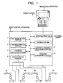
- Fig. 1 is a constitution diagram of a robot system of the invention.
- notations R1, R2, R3, R4 designate robots including electric servomotors at articulated portions.
- the robot also includes one generally referred to as a positioner. That is, the robot indicates one including an articulated portion drive portion.
- a positioner that is, the robot indicates one including an articulated portion drive portion.
- a robot control apparatus 10 controls the robots R1, R2, R3, R4. Although according to the embodiment, an explanation will be given of an example of 4 pieces thereof, 2 pieces or more will do. Further, although with regard also to the robot control apparatus, an explanation will be given of an example of 1 piece thereof according to the embodiment, there may be constructed a constitution of controlling respective robots by a plurality of robot control apparatus.
- the robot control apparatus 10 is connected with an instruction apparatus 11.
- the instruction apparatus 11 includes various keys, a display screen 12.
- the display screen 12 is displayed with a graphical software button, mentioned later, based on a key operation of an operator.
- the software button displays an item which can currently be selected by the operator, a screen or a message in correspondence with the button is newly displayed by selecting the button by the operator.
- the operator can operate a desired robot of the robots R1 through R4 and register a position thereof by operating keys of the instruction apparatus 11. Further, motion and operation of the robot can be programmed by selecting or inputting an instruction displayed on the display screen 12.
- the robot program formed by operating the instruction apparatus 11 is stored to a storing portion at inside of the robot control apparatus 10.
- the robot program is started to execute by the instruction apparatus 11 or other external signal.
- the robot program is executed by a program executing portion 5 at inside of the robot control apparatus 10, and outputs an instruction for servomotors of respective articulated portions of the robots to a servo control portion 6.
- the respective robots are controlled based on the robot program in the above-described procedure.
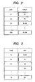
- a unit registration portion 1 registers a combination of a plurality of the robots as a unit.
- Registration is carried out by displaying a table shown in Fig. 2 to the display screen 12 by operating the keys of the instruction apparatus 11 and then further operating the keys of the instruction apparatus 11 by the operator.
- unit 1 (U1) is registered with the robot R1
- a unit 2 (U2) is registered with the robot R2
- a unit 3 (U3) is registered with the robot R1 and the robot R2, respectively.
- a registration number of units is made to be up to 99, the registration number may be made variable in accordance with a number of pieces of the robots connected to the robot control apparatus 10 or operation content.
- the task registration portion 2 registers a relationship between the unit registered by the unit registration portion 1 and a task.
- the tasks are operation units executed independently from each other at inside of the robot control apparatus 10.
- Fig. 3 there are the tasks from T0 to T8, and units of executing operations can be set to the respective tasks.
- the operator executes the settings by operating the keys of the instruction apparatus 11.
- a plurality of the units (U2 + U3) can also be allocated to the single task as in the task T2.
- the task T0 is a special task for governing other tasks, and therefore, the units are not allocated thereto.
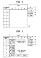
- the graphics language processing portion 3 displays a screen shown in Fig. 4 on the display screen 12 by operating the keys of the instruction apparatus 11.
- notations T0, T1, T2 aligned in a row direction designate the above-described tasks, 0 through 5 aligned in a column direction designate sequence numbers.
- the sequence number is a number allocated for each instruction of a minimum unit constituting the robot program.
- the operator can form a graphical program by arranging a software button or a condition at a program region 40 by operating the keys of the instruction apparatus 11 and software buttons 41 through 44 on the display screen 12.
- the software button 41 signifies a step.
- the step summarizes a series of operation executed by a unit and is identified by combination of 'ST' and a numeral. The operator successively inputs the numeral allocated to the step by operating the keys of the instruction apparatus 11 in selecting the software button 41. Further, step 0 (ST000) is executed at the task T0.
- the software button 42 is used by combining with the software button 43 or 44 in designating transition of executing the program.
- the software button 43 is a conditioned jump function for making execution of the program transit to a designated step when a designated condition is established.
- the software button 44 is an unconditional jump function for making execution transit to an unconditionally designated step.
- Designation of the condition is executed by operating the keys of the instruction apparatus 11 by the operator in selecting the software buttons 43, 44.
- the software button is described not only with a letter but also with a mark in line with meaning thereof, thereby, even other than a skilled operator can easily understand meaning and flow of the program.
- Fig. 5 is an example of a formed graphics program.
- sequence No.2 is conditioned jump, 'IN10 ST001' described therebelow signifies to make the execution transit to step 1 (ST001) when an external signal is inputted to input signal No. 10 at inside of the robot control apparatus 10.
- P100 is executed by the task T1
- P200 is executed by the task T2.
- Notations P100, P200 respectively designate a robot program 100, a robot program 200.
- the robot programs are elements constituting the step, described with the instruction of operating the robot and stored to the storing portion.
- sequence Nos. 3, 4 signify to make execution transit to step 2 (ST002), step 3 (ST003) when an external signal is inputted.
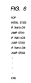
- a program converting portion 4 converts the graphic program shown by Fig. 5 formed by the operator into the robot program. Conversion from the graphic program to the robot program can be executed by the operation of the instruction apparatus 11.
- Fig. 6 shows an example when portions of sequence Nos. 0 through 4 of the graphic program shown in Fig. 5 are converted into the robot program. As described above, the converted robot program is stored to the storing portion.
- the program converting portion 4 converts the robot program into the graphic program conversely to preceding step to display on the display screen 12.
- the operator can play back the selected robot program by operating the keys of the instruction apparatus 11.
- the program execution portion 5 at inside of the robot control apparatus 10 interprets the robot program as shown by Fig. 6 and outputs an instruction to the servo control portion 6, and the respective robots execute operation.
- step 1 when jumped to step 1 (ST001), at the task T1, the robot program 100 (P100) is executed, at the task T2, the robot program 200 (P200) is executed, when the unit combined with the robots R1 and R2 is allocated to the task T1, a unit combined with the robots R3 and R4 is allocated to the task T2, in the robot program 100 (P100), cooperative operation of 2 pieces of the robots R1, R2 is executed, in the robot program 200 (P200), cooperative operation of 2 pieces of the robots R3, R4 is executed.
- the two robot programs are executed in parallel.
- the robot system of the invention there is achieved a significant effect of capable of easily forming operation sequences of a plurality of robots without being accustomed to a special language, further, by graphically displaying the execution state in executing the operation of the robot, the operator can comprehensively determine a current operation situation, and therefore, the robot system of the invention is widely applicable so far as the robot system is a robot system for controlling a plurality of pieces of robots.
Landscapes
- Engineering & Computer Science (AREA)
- Robotics (AREA)
- Mechanical Engineering (AREA)
- Manipulator (AREA)
- Numerical Control (AREA)
Abstract
Description
- The present invention relates to a robot control apparatus and a robot system thereof for controlling a plurality of robots.
- In the article "Approach to cooperative assembly task planning for multiple manipulators", Computer Supported Cooperative Work in Design, Proceedings of the International Conference on Xiamen, China, May 2004, Vol. 1, pages 202-206 by Tianyang Dong et al. a task planning is based on a graphical tool, called "Hierarchical Assembly Precedence Graph" (HAPG). Detailed assembly operations are assigned to the available robots. Execution may be visualized in the form of a "Gantt Chart"
- Further, the article "Cooperative Transport by Multiple Mobile Robots in Unknown Static Environments Associated With Real-time Task Assignment", IEEE Transactions on Robotics Automation, Vol. 18, No. 5, 2002 by Natsuki Miyata et al. describes an architecture for real-time task assignment for a system of multiple robots for cooperatively performing transportation tasks. In particular, besides the actual transportation, the tasks also include searching around the transportation path, in order to detect and remove obstacles, if necessary. Task assignment schemes are graphically visualized, and system performance is evaluated by simulation and experiment.
- A programming environment for robotic systems, called ORCCAD is described in the article "the ORCCAD Architecture", International Journal of Robotics Research, Sage Science Press, Thousand Oaks, USA, Vol. 17, No. 4, pages 338-359, 1998, by J-J. Borrelly et al. The environment provides graphic based tools for programming robot actions in a complex architecture. Basic robot actions are combined into "robot-tasks", while robot-tasks are further logically composed into more complex "robot-procedures".
- As a program of a background art of a robot control apparatus for controlling a plurality of robots, there is a sequence program shown in
Fig. 7 . In a first sequence program shown inFig. 7 , a vertical column thereof is described with steps fromstep 1 throughsteps - Each R item comprises F column, operation column, part column, tool column, location column. F column displays presence/absence of a process continued from a preceding step, and when F column is described with an arrow mark, as in, for example, F column of
step 2 of R3 item, it shows that a process ofstep 1 one step before thereof is continued to process also at step 2 (refer to Patent Reference 1). - Further, an explanation will be given of an apparatus of a background art for displaying a plurality of robot operation programs in reference to
Fig. 8 through Fig. 10 . InFig. 8 , a display region of a display screen of an operation program/state display portion is divided into a mastertask display region 71, asub 1task display region 72, asub 2task display region 73, astate display region 74, and a plurality of operation programs operated synchronizingly in accordance with a flowchart ofFig. 9 are displayed while cooperatively operating the operation programs as shown byFig. 10. Fig. 10 shows the flowchart ofFig. 9 on a left side, shows a state display screen by respective operation programs of robots ofFig. 8 on a right side, and shows a behavior of controlling the display ofFig. 8 by the flowchart ofFig. 9 (refer to Patent Reference 2).
Patent Reference 1:JP-A-6-67709 page 3, right row, line 46 throughpage 4, left row, line 17,Fig. 2 )
Patent Reference 2:JP-A-11-48178 page 3, right row, line 33 throughpage 4, left row,line 3,Fig. 2, Fig. 3 ,Fig. 6 ) - The invention described in
Patent Reference 1 is effective in that when parallel processings are executed for respective robots, programs can be formed for the respective robots. However, an operator cannot comprehensively determine whether processings are executed in parallel by a certain operation unit, or processings are carried out synchronizingly. - For example, in an operation of executing welding for a work, the operation is constituted by a plurality of operation steps of a step of setting a work to a jig, a step of executing welding, a step of reversing the work, a step of executing welding, a step of carrying the work to a next step and the like.
- The invention described in
Patent Reference 1 poses a problem that the operator can determine by only viewing programs with regard to that in relation to the operation steps, which operation step is being executed currently, or under what condition, the execution transits from the operation step to a next step or the like. - On the other hand, according to the invention described in
Patent Reference 2, the operation program of the robot is displayed on the display screen as it is to pose a problem that meaning of a display content is difficult to understand other than a skilled operator. - The invention is for resolving the problems provided to the background arts, and it is an object thereof to provide a robot system capable of simply determining which operation step is executed currently in relation to operation steps, or under what condition execution transits from the operation step to a next step, further, capable of understanding meaning of a display content even by other than a skilled person.
- This is achieved by the features of the independent claims. Further features and advantages of the present invention are the subject matter of dependent claims.
- According to
claim 2, there is provided the robot control apparatus according toclaim 1, wherein
the graphics language processing portion displays a sequence number time-sequentially executed at each row of display member of an instruction apparatus, and displays the robot program executed at the task to each column. - According to
claim 3, there is provided the robot control apparatus according toclaim 2, wherein
the graphics language processing portion makes execution transit to a next step after finishing to execute a current step. - According to
claim 4, there is provided the robot control apparatus according toclaim
the graphics language processing portion makes the execution transmit to a predetermined step based on an external input signal to the robot control apparatus after finishing to execute the current step. - According to
claim 5, there is provided a robot system including: - a plurality of pieces of robots,
- a robot control apparatus according to any one of claims
- The robot system of the invention achieves a significant effect of capable of easily forming an operation sequence of a plurality of robots without being accustomed to a special language, further, in executing operation of the robot, by graphically displaying the execution state, an operator can comprehensively determine a current operational situation.
-
Fig. 1 is a robot system constitution diagram of the invention. -
Fig. 2 is a diagram showing an example of a unit registration screen shown inFig. 1 . -
Fig. 3 is a diagram showing an example of a task registration screen shown inFig. 1 . -
Fig. 4 is a diagram showing an example of a screen of forming a graphics program shown inFig. 1 . -
Fig. 5 is a diagram showing an example of the graphic program formed on the screen shown inFig. 4 . -
Fig. 6 is a diagram showing a robot program in correspondence with the example of the graphic program shown inFig. 5 . -
Fig. 7 is a diagram showing a sequence program of a background art. -
Fig. 8 is a diagram of dividing a region of a display screen of a background art. -
Fig. 9 is a flowchart for explaining a process of the background art. -
Fig. 10 is a diagram showing a behavior of controlling a display of the background art. -
- R1, R2, R3, R4..robots
- 1..unit registration portion
- 2..task registration portion
- 3..graphics
language processing portion 4..program converting portion - 5..program executing portion
- 6..servo control portion
- 10..robot control apparatus
- 11..instruction apparatus
- 40..program region
- 41..software button signifying step
- 42..software button signifying transition
- 43..software button signifying conditioned jump
- 44..software button signifying nonconditional jump
- 71..master task display region
- 72..
sub 1 task display region - 73..
sub 2 task display region - 74..control state display region
- An embodiment of the invention will be explained in reference to
Fig. 1 through Fig. 6 as follows. -
Fig. 1 is a constitution diagram of a robot system of the invention. - In
Fig. 1 , notations R1, R2, R3, R4 designate robots including electric servomotors at articulated portions. Here, the robot also includes one generally referred to as a positioner. That is, the robot indicates one including an articulated portion drive portion. In the following embodiment, an explanation will be given by assuming a case of using 6 axes articulated robot. - A
robot control apparatus 10 controls the robots R1, R2, R3, R4. Although according to the embodiment, an explanation will be given of an example of 4 pieces thereof, 2 pieces or more will do. Further, although with regard also to the robot control apparatus, an explanation will be given of an example of 1 piece thereof according to the embodiment, there may be constructed a constitution of controlling respective robots by a plurality of robot control apparatus. - The
robot control apparatus 10 is connected with aninstruction apparatus 11. Theinstruction apparatus 11 includes various keys, adisplay screen 12. Thedisplay screen 12 is displayed with a graphical software button, mentioned later, based on a key operation of an operator. The software button displays an item which can currently be selected by the operator, a screen or a message in correspondence with the button is newly displayed by selecting the button by the operator. - The operator can operate a desired robot of the robots R1 through R4 and register a position thereof by operating keys of the
instruction apparatus 11. Further, motion and operation of the robot can be programmed by selecting or inputting an instruction displayed on thedisplay screen 12. - The robot program formed by operating the
instruction apparatus 11 is stored to a storing portion at inside of therobot control apparatus 10. The robot program is started to execute by theinstruction apparatus 11 or other external signal. The robot program is executed by aprogram executing portion 5 at inside of therobot control apparatus 10, and outputs an instruction for servomotors of respective articulated portions of the robots to aservo control portion 6. The respective robots are controlled based on the robot program in the above-described procedure. - A
unit registration portion 1 registers a combination of a plurality of the robots as a unit. - Registration is carried out by displaying a table shown in
Fig. 2 to thedisplay screen 12 by operating the keys of theinstruction apparatus 11 and then further operating the keys of theinstruction apparatus 11 by the operator. - In an example of
Fig. 2 , unit 1 (U1) is registered with the robot R1, a unit 2 (U2) is registered with the robot R2, a unit 3 (U3) is registered with the robot R1 and the robot R2, respectively. Although inFig. 2 , a registration number of units is made to be up to 99, the registration number may be made variable in accordance with a number of pieces of the robots connected to therobot control apparatus 10 or operation content. - Successively, a
task registration portion 2 will be explained in reference toFig. 3 . - The
task registration portion 2 registers a relationship between the unit registered by theunit registration portion 1 and a task. The tasks are operation units executed independently from each other at inside of therobot control apparatus 10. - In an example of
Fig. 3 , there are the tasks from T0 to T8, and units of executing operations can be set to the respective tasks. The operator executes the settings by operating the keys of theinstruction apparatus 11. A plurality of the units (U2 + U3) can also be allocated to the single task as in the task T2. However, the task T0 is a special task for governing other tasks, and therefore, the units are not allocated thereto. - Next, a graphics
language processing portion 3 will be explained. - The graphics
language processing portion 3 displays a screen shown inFig. 4 on thedisplay screen 12 by operating the keys of theinstruction apparatus 11. - In
Fig. 4 , notations T0, T1, T2 aligned in a row direction designate the above-described tasks, 0 through 5 aligned in a column direction designate sequence numbers. The sequence number is a number allocated for each instruction of a minimum unit constituting the robot program. - The operator can form a graphical program by arranging a software button or a condition at a
program region 40 by operating the keys of theinstruction apparatus 11 andsoftware buttons 41 through 44 on thedisplay screen 12. - Here, the
software buttons 41 through 44 will be explained. - The
software button 41 signifies a step. The step summarizes a series of operation executed by a unit and is identified by combination of 'ST' and a numeral. The operator successively inputs the numeral allocated to the step by operating the keys of theinstruction apparatus 11 in selecting thesoftware button 41. Further, step 0 (ST000) is executed at the task T0. - The
software button 42 is used by combining with thesoftware button - The
software button 43 is a conditioned jump function for making execution of the program transit to a designated step when a designated condition is established. - On the other hand, the
software button 44 is an unconditional jump function for making execution transit to an unconditionally designated step. - Designation of the condition is executed by operating the keys of the
instruction apparatus 11 by the operator in selecting thesoftware buttons - As shown by
Fig. 4 , the software button is described not only with a letter but also with a mark in line with meaning thereof, thereby, even other than a skilled operator can easily understand meaning and flow of the program. -
Fig. 5 is an example of a formed graphics program. - An explanation will be given by taking an example of sequence No.2 of
Fig. 5 . The sequence No.2 is conditioned jump, 'IN10 ST001' described therebelow signifies to make the execution transit to step 1 (ST001) when an external signal is inputted to input signal No. 10 at inside of therobot control apparatus 10. - As in a row of sequence No.5, at ST001, P100 is executed by the task T1, P200 is executed by the task T2. Notations P100, P200 respectively designate a robot program 100, a robot program 200. The robot programs are elements constituting the step, described with the instruction of operating the robot and stored to the storing portion.
- Further, also sequence Nos. 3, 4 signify to make execution transit to step 2 (ST002), step 3 (ST003) when an external signal is inputted.
- A
program converting portion 4 converts the graphic program shown byFig. 5 formed by the operator into the robot program. Conversion from the graphic program to the robot program can be executed by the operation of theinstruction apparatus 11. -
Fig. 6 shows an example when portions of sequence Nos. 0 through 4 of the graphic program shown inFig. 5 are converted into the robot program. As described above, the converted robot program is stored to the storing portion. - At sequence Nos. 0 through 4, only the task T0 is described, as described above, the task T0 is the task for governing other tasks, and therefore, an instruction of operating the robot is not included in
Fig. 6 . - Successively, an explanation will be given of execution (play back) of the robot program formed as described above.
- When the operator selects a desired one from the robot programs stored to the storing portion by operating the keys of the
instruction apparatus 11, theprogram converting portion 4 converts the robot program into the graphic program conversely to preceding step to display on thedisplay screen 12. - Further, the operator can play back the selected robot program by operating the keys of the
instruction apparatus 11. Specifically, theprogram execution portion 5 at inside of therobot control apparatus 10 interprets the robot program as shown byFig. 6 and outputs an instruction to theservo control portion 6, and the respective robots execute operation. - In the example of
Fig. 5 , when jumped to step 1 (ST001), at the task T1, the robot program 100 (P100) is executed, at the task T2, the robot program 200 (P200) is executed, when the unit combined with the robots R1 and R2 is allocated to the task T1, a unit combined with the robots R3 and R4 is allocated to the task T2, in the robot program 100 (P100), cooperative operation of 2 pieces of the robots R1, R2 is executed, in the robot program 200 (P200), cooperative operation of 2 pieces of the robots R3, R4 is executed. At this occasion, the two robot programs are executed in parallel. - Further, in play back time, such that the operator is easy to optically recognize the display, when the
display screen 12 is a monochromatic display, only a portion of being executed at inside of theprogram region 40 is invertedly displayed, when thedisplay screen 12 corresponds to multicolor display, only a portion of being executed at inside of theprogram region 40 is changed in color thereof, thereby, a currently executing portion in the program is displayed. - As described above, according to the robot system of the invention, there is achieved a significant effect of capable of easily forming operation sequences of a plurality of robots without being accustomed to a special language, further, by graphically displaying the execution state in executing the operation of the robot, the operator can comprehensively determine a current operation situation, and therefore, the robot system of the invention is widely applicable so far as the robot system is a robot system for controlling a plurality of pieces of robots.
- The application is based on Japanese Patent Application, Japanese Patent Application No.
2004-319169 filed on November 2, 2004 - [
Fig. 1 ]- 1: unit registration portion
- 2: task registration portion
- 3: graphics language processing portion
- 4: program converting portion
- 5: program executing portion
- 6: servo control portion
- 10: robot control apparatus
- 11: instruction apparatus
- 12: display screen
- A1: interface portion
- A2: storing portion
- A3: external signal
- [
Fig. 2 ]- A1: unit
- A2: robot
- [
Fig. 3 ]- A1: task
- A2: unit
- A3: none
- [
Fig. 4 ]- A1: sequence No.
- A2: task
- [
Fig. 5 ]- A1: sequence No.
- A2: task
- A3: inside of dotted line is ST000
- A4: inside of dotted line is ST001
- [
Fig. 7 ]- A1: first sequence program
- A2: step
- A3: R2 item
- A4: R1 item
- A5: R3 item
- A6: operation
- A7: part
- A8: tool
- A9: location
- [
Fig. 8 ]- 71: master task display region
- 72: sub 1 task display region
- 73: sub 2 task display region
- 74: state display region
- [
Fig. 9 ]- 110: read operation input from display/select portion
- 120: which is current task?
- 130: master task command execution process
- 140: sub 1 task command execution process
- 150: cooperative execution mode?
- 180: sub 2 task command execution process
- 170: sub 2 task command execution process
- 180: cooperative operation mode?
- 190: sub 1 task command execution process
- A1:
sub 1 - A2:
sub 2 - A3: yes
- A4: no
- A5: master
- [
Fig. 10 ]- A1: move cursor
- A2:
sub 1 - A3: mode: [cooperative operation] current task: [sub 2]
Claims (5)
- A robot control apparatus adapted for controlling a plurality of robots (R1, R2, R3, R4) simultaneously based on a robot program,said robot control apparatus comprising:a unit registration portion (1) adapted for arbitrarily combining one or more of the plurality of robots a unit registration portion (1) for arbitrarily combining one or more of the plurality of robots (R1, R2, R3, R4) to define a unit,a task registration portion (2) adapted for allocating a task for each of the units,a graphics language processing portion (3) adapted for forming the robot program as a graphical program for each of the tasks, anda program converting portion (4) adapted for converting the graphical program into the robot program, whereinsaid program converting portion (4) converts said robot program conversely into the graphical program for visually indicating the execution of the robot program on a display member (12) of an instruction apparatus (11), andsaid graphical program visualizes the robot program as an array of columns, each corresponding to one of said tasks allocated to said units, and rows, each corresponding to a sequence number of processing time-sequentially executed, wherein one of the rows corresponds to a sequence number of processing executed for each of the tasks in parallel.
- The robot control apparatus according to claim 1, wherein said graphical program is displayed during execution of the robot program such that a manner of display is changed for a program portion that is currently executed.
- The robot control apparatus according to claim 1 or 2, wherein the graphics language processing portion (3) makes execution transit to a next step after finishing to execute a current step.
- The robot control apparatus according to any of claims 1 to 3, wherein the graphics language processing portion (3) makes the execution transit to a predetermined step based on an external input signal to the robot control apparatus after finishing to execute the current step.
- A robot system comprising:a plurality of robots (R1, R2, R3, R4),a robot control apparatus (10) according to any one of claims 1 to 4 for simultaneously controlling the plurality of robots (R1, R2, R3, R4) based on a robot program, anda robot instruction apparatus (11) connected to the robot control apparatus (10) and including a display member (12) and an edit member of the robot program.
Applications Claiming Priority (2)
| Application Number | Priority Date | Filing Date | Title |
|---|---|---|---|
| JP2004319169A JP4744847B2 (en) | 2004-11-02 | 2004-11-02 | Robot control device and robot system |
| PCT/JP2005/020213 WO2006049210A1 (en) | 2004-11-02 | 2005-11-02 | Robot controller and robot system |
Publications (3)
| Publication Number | Publication Date |
|---|---|
| EP1815951A1 EP1815951A1 (en) | 2007-08-08 |
| EP1815951A4 EP1815951A4 (en) | 2010-11-03 |
| EP1815951B1 true EP1815951B1 (en) | 2012-02-29 |
Family
ID=36319215
Family Applications (1)
| Application Number | Title | Priority Date | Filing Date |
|---|---|---|---|
| EP05805507A Expired - Fee Related EP1815951B1 (en) | 2004-11-02 | 2005-11-02 | Robot controller and robot system |
Country Status (6)
| Country | Link |
|---|---|
| US (1) | US8396599B2 (en) |
| EP (1) | EP1815951B1 (en) |
| JP (1) | JP4744847B2 (en) |
| CN (1) | CN100551635C (en) |
| ES (1) | ES2380625T3 (en) |
| WO (1) | WO2006049210A1 (en) |
Cited By (2)
| Publication number | Priority date | Publication date | Assignee | Title |
|---|---|---|---|---|
| CN104470686A (en) * | 2012-06-01 | 2015-03-25 | 奥尔德巴伦机器人公司 | System and method for generating contextual behaviours of a mobile robot executed in real time |
| CN109426560A (en) * | 2017-08-28 | 2019-03-05 | 杭州海康机器人技术有限公司 | Method for allocating tasks, device and computer readable storage medium |
Families Citing this family (14)
| Publication number | Priority date | Publication date | Assignee | Title |
|---|---|---|---|---|
| EP1776624A1 (en) | 2004-06-24 | 2007-04-25 | iRobot Corporation | Programming and diagnostic tool for a mobile robot |
| US11209833B2 (en) | 2004-07-07 | 2021-12-28 | Irobot Corporation | Celestial navigation system for an autonomous vehicle |
| US7706917B1 (en) | 2004-07-07 | 2010-04-27 | Irobot Corporation | Celestial navigation system for an autonomous robot |
| US8972052B2 (en) | 2004-07-07 | 2015-03-03 | Irobot Corporation | Celestial navigation system for an autonomous vehicle |
| US8930023B2 (en) | 2009-11-06 | 2015-01-06 | Irobot Corporation | Localization by learning of wave-signal distributions |
| US7383100B2 (en) * | 2005-09-29 | 2008-06-03 | Honda Motor Co., Ltd. | Extensible task engine framework for humanoid robots |
| WO2009097895A1 (en) * | 2008-02-05 | 2009-08-13 | Abb Technology Ab | An industrial robot system |
| JP2010120095A (en) * | 2008-11-17 | 2010-06-03 | Yaskawa Electric Corp | Robot system |
| CN103213125B (en) * | 2011-11-04 | 2016-05-18 | 范努克机器人技术美国有限公司 | There is robot teaching's device that 3D shows |
| US9008839B1 (en) * | 2012-02-07 | 2015-04-14 | Google Inc. | Systems and methods for allocating tasks to a plurality of robotic devices |
| JP5862611B2 (en) * | 2013-04-02 | 2016-02-16 | トヨタ自動車株式会社 | Work change device, work change method, and work change program |
| KR101458707B1 (en) * | 2013-05-30 | 2014-11-05 | 한전케이피에스 주식회사 | System for controlling end-effector of automatic robot and method thereof |
| JP6969283B2 (en) | 2017-10-25 | 2021-11-24 | オムロン株式会社 | Control system |
| JP7069971B2 (en) * | 2018-03-30 | 2022-05-18 | セイコーエプソン株式会社 | Controls, robots, and robot systems |
Family Cites Families (24)
| Publication number | Priority date | Publication date | Assignee | Title |
|---|---|---|---|---|
| US5260868A (en) | 1986-08-11 | 1993-11-09 | Texas Instruments Incorporate | Method for calendaring future events in real-time |
| US4896269A (en) * | 1988-02-29 | 1990-01-23 | General Electric Company | Job shop scheduling and production method and apparatus |
| CA2007140A1 (en) | 1989-08-09 | 1991-02-09 | Toshiji Senda | Method of sequence control |
| JPH04201081A (en) * | 1990-11-29 | 1992-07-22 | Honda Motor Co Ltd | Control unit for robot |
| US5260668A (en) * | 1992-06-11 | 1993-11-09 | Prometrix Corporation | Semiconductor surface resistivity probe with semiconductor temperature control |
| JPH0667709A (en) * | 1992-06-17 | 1994-03-11 | Fujitsu Ltd | Method and device for generating sequence program and sequence controller |
| US5675229A (en) * | 1994-09-21 | 1997-10-07 | Abb Robotics Inc. | Apparatus and method for adjusting robot positioning |
| JPH08249026A (en) * | 1995-03-10 | 1996-09-27 | Fanuc Ltd | Programming method for system including robot |
| DE69618606T2 (en) * | 1995-09-19 | 2002-09-12 | Yaskawa Denki Kitakyushu Kk | PROCESSOR FOR ROBOT LANGUAGE |
| JPH09244730A (en) * | 1996-03-11 | 1997-09-19 | Komatsu Ltd | Robot system and controller for robot |
| JP3427918B2 (en) | 1996-07-02 | 2003-07-22 | インターナショナル・ビジネス・マシーンズ・コーポレーション | Program development support system and support method |
| JP3832686B2 (en) | 1997-08-08 | 2006-10-11 | 株式会社安川電機 | Robot operation program display device and control device |
| JPH11194810A (en) * | 1998-01-06 | 1999-07-21 | Okuma Corp | Nc information editing device |
| US6243857B1 (en) * | 1998-02-17 | 2001-06-05 | Nemasoft, Inc. | Windows-based flowcharting and code generation system |
| US6061602A (en) * | 1998-06-23 | 2000-05-09 | Creative Lifestyles, Inc. | Method and apparatus for developing application software for home automation system |
| US6266577B1 (en) * | 1998-07-13 | 2001-07-24 | Gte Internetworking Incorporated | System for dynamically reconfigure wireless robot network |
| DE19910311A1 (en) * | 1999-03-09 | 2000-09-14 | Siemens Ag | Automation system with reusable automation objects and process for reusing automation solutions in engineering tools |
| JP3708357B2 (en) * | 1999-04-01 | 2005-10-19 | 松下電器産業株式会社 | Robot controller |
| JP3538362B2 (en) * | 1999-09-16 | 2004-06-14 | ファナック株式会社 | Synchronous or cooperative operation control device for multiple robots |
| AT412196B (en) * | 2000-03-17 | 2004-11-25 | Keba Ag | METHOD FOR ASSIGNING A MOBILE OPERATING AND / OR OBSERVATION DEVICE TO A MACHINE AND OPERATING AND / OR OBSERVATION DEVICE THEREFOR |
| JP4592919B2 (en) * | 2000-10-26 | 2010-12-08 | シチズンホールディングス株式会社 | Automatic programming method and automatic programming apparatus |
| US6408226B1 (en) * | 2001-04-24 | 2002-06-18 | Sandia Corporation | Cooperative system and method using mobile robots for testing a cooperative search controller |
| US6975921B2 (en) * | 2001-11-09 | 2005-12-13 | Asm International Nv | Graphical representation of a wafer processing process |
| US20040134336A1 (en) * | 2002-04-22 | 2004-07-15 | Neal Solomon | System, methods and apparatus for aggregating groups of mobile robotic vehicles |
-
2004
- 2004-11-02 JP JP2004319169A patent/JP4744847B2/en active Active
-
2005
- 2005-11-02 ES ES05805507T patent/ES2380625T3/en active Active
- 2005-11-02 EP EP05805507A patent/EP1815951B1/en not_active Expired - Fee Related
- 2005-11-02 US US11/718,441 patent/US8396599B2/en active Active
- 2005-11-02 WO PCT/JP2005/020213 patent/WO2006049210A1/en active Application Filing
- 2005-11-02 CN CNB2005800381695A patent/CN100551635C/en active Active
Cited By (2)
| Publication number | Priority date | Publication date | Assignee | Title |
|---|---|---|---|---|
| CN104470686A (en) * | 2012-06-01 | 2015-03-25 | 奥尔德巴伦机器人公司 | System and method for generating contextual behaviours of a mobile robot executed in real time |
| CN109426560A (en) * | 2017-08-28 | 2019-03-05 | 杭州海康机器人技术有限公司 | Method for allocating tasks, device and computer readable storage medium |
Also Published As
| Publication number | Publication date |
|---|---|
| EP1815951A1 (en) | 2007-08-08 |
| US8396599B2 (en) | 2013-03-12 |
| JP4744847B2 (en) | 2011-08-10 |
| CN100551635C (en) | 2009-10-21 |
| US20080009973A1 (en) | 2008-01-10 |
| ES2380625T3 (en) | 2012-05-16 |
| WO2006049210A1 (en) | 2006-05-11 |
| JP2006130577A (en) | 2006-05-25 |
| EP1815951A4 (en) | 2010-11-03 |
| CN101056744A (en) | 2007-10-17 |
Similar Documents
| Publication | Publication Date | Title |
|---|---|---|
| EP1815951B1 (en) | Robot controller and robot system | |
| Akan et al. | Intuitive industrial robot programming through incremental multimodal language and augmented reality | |
| Makris et al. | Dual arm robot in cooperation with humans for flexible assembly | |
| JP2786225B2 (en) | Industrial robot control method and apparatus | |
| US7194396B2 (en) | Simulation device | |
| CN1758990B (en) | Robot simulation device | |
| JP3819883B2 (en) | Robot program position correction device | |
| CN110573308A (en) | mixed reality assisted space programming for robotic systems | |
| US20090018690A1 (en) | Method of controlling a robotic work station and a corresponding robotic work station | |
| CN109129413B (en) | Robot system capable of displaying speed | |
| JP2003150218A (en) | Simulation device | |
| Schäffer et al. | System architecture and conception of a standardized robot configurator based on microservices | |
| US5815399A (en) | Multi-path synchronization system for CNC controller | |
| JP2013226602A (en) | Industrial machine system | |
| JP2019171498A (en) | Robot program execution device, robot program execution method and program | |
| Teubner et al. | Approaching Dynamic and Individual Worker Information Systems | |
| JP2009211369A (en) | Operation simulator for numerically controlled machine | |
| JPH045702A (en) | Control program generating device | |
| JPH08137532A (en) | Generating method for operation program of robot and teaching method for robot | |
| JPH09305213A (en) | Robot controller | |
| Williams | Development of a Cobot Lab to Support Next-Generation Applied Engineering Technology | |
| JPH01269105A (en) | Off-line programming device | |
| Parsons | Robot programming | |
| EP0871097A1 (en) | Programmable controller | |
| CN112975905A (en) | Support device for programming the operation of a robot |
Legal Events
| Date | Code | Title | Description |
|---|---|---|---|
| PUAI | Public reference made under article 153(3) epc to a published international application that has entered the european phase |
Free format text: ORIGINAL CODE: 0009012 |
|
| 17P | Request for examination filed |
Effective date: 20070430 |
|
| AK | Designated contracting states |
Kind code of ref document: A1 Designated state(s): DE ES FR IT |
|
| DAX | Request for extension of the european patent (deleted) | ||
| RBV | Designated contracting states (corrected) |
Designated state(s): DE ES FR IT |
|
| RBV | Designated contracting states (corrected) |
Designated state(s): DE ES FR IT |
|
| A4 | Supplementary search report drawn up and despatched |
Effective date: 20101006 |
|
| REG | Reference to a national code |
Ref country code: DE Ref legal event code: R079 Ref document number: 602005032939 Country of ref document: DE Free format text: PREVIOUS MAIN CLASS: B25J0013000000 Ipc: B25J0009160000 |
|
| RIC1 | Information provided on ipc code assigned before grant |
Ipc: B25J 9/16 20060101AFI20110830BHEP |
|
| GRAP | Despatch of communication of intention to grant a patent |
Free format text: ORIGINAL CODE: EPIDOSNIGR1 |
|
| GRAS | Grant fee paid |
Free format text: ORIGINAL CODE: EPIDOSNIGR3 |
|
| GRAA | (expected) grant |
Free format text: ORIGINAL CODE: 0009210 |
|
| AK | Designated contracting states |
Kind code of ref document: B1 Designated state(s): DE ES FR IT |
|
| REG | Reference to a national code |
Ref country code: DE Ref legal event code: R096 Ref document number: 602005032939 Country of ref document: DE Effective date: 20120426 |
|
| REG | Reference to a national code |
Ref country code: ES Ref legal event code: FG2A Ref document number: 2380625 Country of ref document: ES Kind code of ref document: T3 Effective date: 20120516 |
|
| PLBE | No opposition filed within time limit |
Free format text: ORIGINAL CODE: 0009261 |
|
| STAA | Information on the status of an ep patent application or granted ep patent |
Free format text: STATUS: NO OPPOSITION FILED WITHIN TIME LIMIT |
|
| 26N | No opposition filed |
Effective date: 20121130 |
|
| REG | Reference to a national code |
Ref country code: DE Ref legal event code: R097 Ref document number: 602005032939 Country of ref document: DE Effective date: 20121130 |
|
| REG | Reference to a national code |
Ref country code: FR Ref legal event code: PLFP Year of fee payment: 11 |
|
| REG | Reference to a national code |
Ref country code: FR Ref legal event code: PLFP Year of fee payment: 12 |
|
| PGFP | Annual fee paid to national office [announced via postgrant information from national office to epo] |
Ref country code: DE Payment date: 20161025 Year of fee payment: 12 Ref country code: FR Payment date: 20161014 Year of fee payment: 12 |
|
| PGFP | Annual fee paid to national office [announced via postgrant information from national office to epo] |
Ref country code: IT Payment date: 20161122 Year of fee payment: 12 Ref country code: ES Payment date: 20161011 Year of fee payment: 12 |
|
| REG | Reference to a national code |
Ref country code: DE Ref legal event code: R119 Ref document number: 602005032939 Country of ref document: DE |
|
| REG | Reference to a national code |
Ref country code: FR Ref legal event code: ST Effective date: 20180731 |
|
| PG25 | Lapsed in a contracting state [announced via postgrant information from national office to epo] |
Ref country code: IT Free format text: LAPSE BECAUSE OF NON-PAYMENT OF DUE FEES Effective date: 20171102 Ref country code: FR Free format text: LAPSE BECAUSE OF NON-PAYMENT OF DUE FEES Effective date: 20171130 Ref country code: DE Free format text: LAPSE BECAUSE OF NON-PAYMENT OF DUE FEES Effective date: 20180602 |
|
| REG | Reference to a national code |
Ref country code: ES Ref legal event code: FD2A Effective date: 20181226 |
|
| PG25 | Lapsed in a contracting state [announced via postgrant information from national office to epo] |
Ref country code: ES Free format text: LAPSE BECAUSE OF NON-PAYMENT OF DUE FEES Effective date: 20171103 |