JP3832686B2 - Robot operation program display device and control device - Google Patents
Robot operation program display device and control device Download PDFInfo
- Publication number
- JP3832686B2 JP3832686B2 JP21533597A JP21533597A JP3832686B2 JP 3832686 B2 JP3832686 B2 JP 3832686B2 JP 21533597 A JP21533597 A JP 21533597A JP 21533597 A JP21533597 A JP 21533597A JP 3832686 B2 JP3832686 B2 JP 3832686B2
- Authority
- JP
- Japan
- Prior art keywords
- execution unit
- task
- operation program
- unit
- robot
- Prior art date
- Legal status (The legal status is an assumption and is not a legal conclusion. Google has not performed a legal analysis and makes no representation as to the accuracy of the status listed.)
- Expired - Fee Related
Links
Images


Landscapes
- Numerical Control (AREA)
- Manipulator (AREA)
Description
【0001】
【発明の属する技術分野】
本発明は、ロボットの動作プログラム表示装置に関し、特に複数の動作プログラムを同時に実行または教示する場合の動作プログラムの表示装置に関する。
【0002】
【従来の技術】
一つの制御装置で複数のロボットあるいは外部軸毎に動作プログラムを記述し、それぞれの動作プログラムを独立かつ同時に実行する場合、従来の制御装置では、画面に表示される動作プログラムは一つだけであり、他の動作プログラムの実行状態を確認するためには、キー操作によって画面を切り替える必要があった。
【0003】
【発明が解決しようとする問題点】
ところが、従来技術では、それぞれ独立に動作している動作プログラムを表示部で確認するには、頻繁に画面を切り替えなければならない。また、ある時点でのそれぞれのプログラムの実行位置を、同時に確認することが出来ない。
さらに、複数のプログラム間で、それぞれのステップ同士を同期させながら動作させる動作プログラムの教示の際、それぞれの動作プログラム間でのステップの対応が理解し難い。
そこで、本発明は、複数の動作プログラムの実行状態を一つの画面で同時に確認することが出来る動作プログラムの表示装置を提供することを目的とする。
【0004】
【課題を解決するための手段】
上記課題を解決するため、本発明は、次のように構成したのである。
請求項1に記載の発明は、複数のロボットの動作を記述する複数の動作プログラムのそれぞれの実行状況を同時に表示する表示手段と、少なくともマスタタスク実行部、第1サブタスク実行部、および第2サブタスク実行部からなり、前記マスタタスク実行部、前記第1サブタスク実行部、および前記第2サブタスク実行部において前記動作プログラムを実行する動作プログラム実行部と、少なくとも前記第1サブタスク実行部または前記第2サブタスク実行部のいずれかを選択するためのタスク選択手段と、を備えたロボット制御装置において、前記タスク選択手段により選択された前記第1及び前記第2サブタスク実行部のいずれか一方を動作させる第1の動作モード、又は前記第1及び前記第2サブタスク実行部の両方を同期動作させる第2の動作モードのいずれかを選択するための動作モード切り替え手段と、前記第1サブタスク実行部および前記第2サブタスク実行部においてそれぞれ実行される前記動作プログラムの各プログラムステップ同士を同期させながら動作させる同期手段と、ロボット動作の教示を行う教示モード時に、前記動作モード切り替え手段によって前記第1の動作モードが選択されている場合は、前記タスク選択手段により選択されたサブタスク実行部に対して、前記表示手段に表示されたカーソルを移動させるカーソル移動コマンドまたは前記カーソルの位置する前記プログラムステップへ前記ロボットを動作させるネクスト操作コマンドの実行処理を行う第1のステップを実行し、前記動作モード切り替え手段によって前記第2の動作モードが選択されている場合は、前記同期手段によって前記動作プログラムステップが同期した状態で、前記第1のステップに加えて、前記タスク選択手段により選択されたサブタスク実行部以外のサブタスク実行部に対して、前記第1のステップにおいて実行処理されたコマンドと同一のコマンドの実行処理を行う第2のステップを実行する手段と、を備えたことを特徴とするものである。
請求項2に記載の発明は、前記第1と第2の動作モードは教示中に切替え可能であることを特徴とするものである。
請求項3に記載の発明は、請求項1乃至2いずれかに記載のロボットの動作プログラム表示装置を備えたことを特徴とするものである。
【0005】
【発明の実施の形態】
以下、本発明の実施例を図に基づいて説明する。
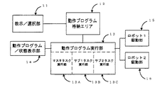
図1は、本発明を実施するためのシステムの例を示すブロック図であり、図中11は教示/選択部、12は動作プログラム格納エリア、13は動作プログラム実行部、14は動作プログラム/状態表示部、15はロボット1駆動部、16はロボット2駆動部である。
動作プログラム実行部13は、マスタタスク実行部13A、サブ1タスク実行部13B、サブ2タスク実行部13Cからなる。
図2は、上記動作プログラム/状態表示部14における表示画面の、表示領域の分割の例であり、図中21はマスタタスク表示領域、22はサブ1タスク表示領域、23はサブ2タスク表示領域、24は各種制御状態表示領域である。この動作プログラム/状態表示部14における各表示領域は、キー操作によって、任意の表示領域のサイズの変更や、領域同士の配置状態の選択などが行える。
【0006】
(1)図1のシステムにおいて、教示/選択部11より、マスタタスク実行部13Aにて実行する動作プログラム(以下、マスタタスクジョブという)を選択して実行する。動作プログラム実行部13は、マスタタスク実行部13Aにおいてマスタタスクジョブを実行するとともに、マスタタスク表示領域21へマスタタスクジョブの動作状況のデータを転送する。このマスタタスクジョブにおいて、特定の命令を実行することにより、サブ1タスク実行部13Bまたはサブ2タスク実行部13Cにて、指定された動作プログラム(以下サブ1タスクジョブ、サブ2タスクジョブという)が実行される。
動作プログラム実行部13は、各サブタスク実行部においてそれぞれ動作プログラムを独立に実行するとともに、動作状況のデータを動作プログラム/状態表示部14へ転送する。
動作プログラム/状態表示部14は、動作プログラム実行部13より転送された各タスク実行部の状態を、それぞれ対応する表示領域へ表示する。サブ1タスクジョブまたはサブ2タスクジョブが選択されていない状態では、それぞれに対応する表示領域を空白表示とするか、あるいは「ジョブ未選択」等のメッセージを表示するなどして、サブ1タスクジョブまたはサブ2タスクジョブが選択されていないことを表現する。または、マスタタスク表示領域を拡大して、マスタタスクジョブのみが表示されるようにすることもできる。さらに、任意のタスク実行部を選択して、そのタスク実行部の動作プログラムを拡大表示するようにしてもよい。
教示/選択部11は、ロボットを動作させる軸操作キーや、各動作プログラム上のステップを選択するためのカーソルキー、操作する際のメインとなるタスク実行部(以下、カレントタスク実行部という)を選択するためのタスク切替キー等を備える。タスク切替キーによって選択されたカレントタスク実行部は、その表示領域を強調表示する。動作プログラムにおいてロボットの動作を記述したステップにカーソルを置き、専用のキーを押すことによって、押している間、そのステップへロボットを一定の速度で動作させることができる。この操作(以下、この操作を「ネクスト」操作という。)によって教示位置の確認を行う。ネクスト操作を行うと、動作プログラム実行部13は、選択されているタスク実行部の、カーソルのあるステップの情報を動作プログラム格納エリア12より読み出し、ロボットを動作させる。
【0007】
(2)上記のシステムにおいて、サブ1タスク実行部13Bとサブ2タスク実行部13Cの間で、各ステップを同期させながら作業を行うこともできる。例えば、左右対称ワークに対して、同機種のロボットを左右に2台並べて、それぞれをサブ1タスク実行部13B、サブ2タスク実行部13Cで動作させ、同時に左右対称の作業を行う場合がその例である。上記のような同期作業の教示を確認する場合、まず、教示/選択部11からの操作により、サブ1タスク実行部13Bとサブ2タスク実行部13Cを同期させる「連動モード」か、あるいはそれぞれ選択した側のタスク実行部のみを動作させる「単独モード」かを予め選択する。このモード選択は、教示中に任意に切り替えられる。「単独モード」が選択されている場合、動作プログラム上のカーソル移動やネクスト操作は、その時に選択されているタスク実行部についてのみ行う。一方、「連動モード」が選択されている場合、カーソル移動やネクスト操作は、サブ1タスク実行部13Bとサブ2タスク実行部13Cの両方において、同時に行われる。
【0008】
図3および図4は、本発明における動作プログラム実行部13での、教示モードでの操作に対する処理に関するフローチャートである。この処理は、教示/選択部11にてキー操作が行われた場合に、その操作内容をコマンドとして起動される。具体的に説明すると、次のようになる。
[図3]
ステップ110:教示/選択部11より、操作入力の内容を、コマンドとして読み込む。
ステップ120:どのタスク実行部がカレントタスク実行部として選択されているかを判断し、それがマスタタスク実行部13Aならステップ130へ、サブ1タスク実行部13Bならステップ140へ、サブ2タスク実行部13Cならステップ170へ、それぞれ進む。
ステップ130:マスタタスク実行部13Aに対してコマンド実行処理を行い、終了する。
ステップ140:サブ1タスク実行部13Bに対してコマンド実行処理を行う。
ステップ150:連動モードかどうかの判定を行う。連動モードの場合はステップ160に進み、そうでなければ終了する。
ステップ160:サブ2タスク実行部13Cに対してコマンド実行処理を行う。
ステップ170:サブ2タスク実行部13Cに対してコマンド実行処理を行う。
ステップ180:連動モードかどうかの判定を行う。連動モードの場合はステップ190に進み、そうでなければ終了する。
ステップ190:サブ1タスク実行部13Bに対してコマンド実行処理を行う。
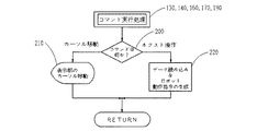
[図4 コマンド実行処理]
ステップ200:コマンドが「カーソル移動」か「ネクスト操作」かを判断し、カーソル移動ならステップ210へ、ネクスト操作ならステップ220へ進む。
ステップ210:カーソル移動コマンドに基づき、教示部のカーソル移動を行う。
ステップ220:ネクスト操作コマンドに基づき、データ読み込み及びロボット動作指令の生成を行う。
【0009】
図5および図6は、図3のフローチャートにより、実際に動作プログラム/状態表示部14における表示が制御される様子を表したものである。左側に図3のフローチャートを示し、右側には、図2に示した動作プログラム/状態表示部14での表示画面の様子を示している。この図では、サブ1タスク実行部13B、サブ2タスク実行部13Cがともに同期できるジョブが起動され、カレントタスク実行部はサブ2タスク実行部13Cである。ここで、教示/選択部11にて、カーソルを1ライン分下方へ動かすような操作が行われたとする。
図5は、単独モードの場合である。ステップ120で、カレントタスク実行部がサブ2タスク実行部であるので、ステップ170が実行され、サブ2タスク表示領域23のカーソルが、1ライン分下方へ移動する。
一方、図6は、連動モードの場合を示している。ステップ120で、カレントタスク実行部がサブ2タスク実行部であるので、ステップ170が実行され、サブ2タスク表示領域23のカーソルが、1ライン分下方へ移動する。さらに、連動モードであるため、ステップ180の判断により、ステップ190が実行され、サブ1タスク表示領域22のカーソルも、1ライン分下方へ移動する。
【0010】
【発明の効果】
以上述べたように、本発明によれば、独立に動作している動作プログラムのそれぞれの動作状態を、一目で確認することが出来るため、動作確認が容易で、しかも画面を切り替えるなどの煩雑な操作が不要になる。
さらに、同期して動く複数の動作プログラムを、連動させながら表示することにより、プログラム間の同期の確認が容易に行える。
【図面の簡単な説明】
【図1】本発明の実施例を示すブロック図である。
【図2】本発明の実施例における表示画面の領域分割の図である。
【図3】本発明の実施例の動作プログラム実行部での、各タスクの概略処理に関するフローチャートである。
【図4】本発明の実施例のコマンド実行処理を示すフローチャートである。
【図5】本発明の実施例の動作プログラム/状態表示部において、表示が制御される様子を表した単独モードの説明図である。
【図6】本発明の実施例の動作プログラム/状態表示部において、表示が制御される様子を表した連動モードの説明図である。
【符号の説明】
11 教示/選択部
12 動作プログラム格納エリア
13 動作プログラム実行部
13A マスタタスク実行部
13B サブ1タスク実行部
13C サブ2タスク実行部
14 動作プログラム/状態表示部
15 ロボット1駆動部
16 ロボット2駆動部
21 マスタタスク表示領域
22 サブ1タスク表示領域
23 サブ2タスク表示領域
24 制御状態表示領域[0001]
BACKGROUND OF THE INVENTION
The present invention relates to an operation program display device for a robot, and more particularly to an operation program display device for simultaneously executing or teaching a plurality of operation programs.
[0002]
[Prior art]
When a single control device describes an operation program for each robot or external axis and executes each operation program independently and simultaneously, the conventional control device has only one operation program displayed on the screen. In order to check the execution state of other operation programs, it was necessary to switch the screen by key operation.
[0003]
[Problems to be solved by the invention]
However, in the prior art, in order to check the operation program operating independently of each other on the display unit, the screen must be frequently switched. Also, the execution position of each program at a certain time cannot be confirmed at the same time.
Furthermore, when teaching an operation program that operates while synchronizing each step among a plurality of programs, it is difficult to understand the correspondence of the steps between the operation programs.
Therefore, an object of the present invention is to provide an operation program display device that can simultaneously check the execution state of a plurality of operation programs on a single screen.
[0004]
[Means for Solving the Problems]
In order to solve the above problems, the present invention is configured as follows.
According to the first aspect of the present invention, there is provided display means for simultaneously displaying execution states of a plurality of operation programs describing operations of a plurality of robots, at least a master task execution unit, a first subtask execution unit, and a second subtask An operation program execution unit that executes the operation program in the master task execution unit, the first subtask execution unit, and the second subtask execution unit, and at least the first subtask execution unit or the second subtask in the robot control apparatus and a task selection means for selecting one of the execution unit, the operating one of the first and the second sub-tasks execution unit selected by the
The invention described in
According to a third aspect of the invention, there is provided the robot operation program display device according to the first or second aspect.
[0005]
DETAILED DESCRIPTION OF THE INVENTION
Embodiments of the present invention will be described below with reference to the drawings.
FIG. 1 is a block diagram showing an example of a system for carrying out the present invention, in which 11 is a teaching / selection unit, 12 is an operation program storage area, 13 is an operation program execution unit, and 14 is an operation program / state. A display unit, 15 is a
Operation
FIG. 2 shows an example of the display area division of the display screen in the operation program / status display section 14, where 21 is a master task display area, 22 is a
[0006]
(1) In the system of FIG. 1, the teaching / selecting unit 11 selects and executes an operation program (hereinafter referred to as a master task job) to be executed by the master task execution unit 13A. The operation
The operation
The operation program / status display unit 14 displays the status of each task execution unit transferred from the operation
The teaching / selecting unit 11 includes an axis operation key for operating the robot, a cursor key for selecting a step on each operation program, and a main task execution unit (hereinafter referred to as a current task execution unit ) for operation. A task switching key for selection is provided. The current task execution unit selected by the task switching key highlights the display area. By placing the cursor on a step describing the robot operation in the operation program and pressing a dedicated key, the robot can be moved to that step at a constant speed while it is being pressed. The teaching position is confirmed by this operation (hereinafter, this operation is referred to as “next” operation). When the next operation is performed, the operation
[0007]
(2) In the above-described system, work can be performed while synchronizing each step between the
[0008]
FIG. 3 and FIG. 4 are flowcharts relating to processing for operation in the teaching mode in the operation
[ Figure 3 ]
Step 110: Read the contents of the operation input from the teaching / selection unit 11 as a command.
Step 120: Determine which task execution unit is selected as the current task execution unit . If it is the master task execution unit 13A, go to
Step 130: Command execution processing is performed on the master task execution unit 13A, and the process ends.
Step 140: Command execution processing is performed on the
Step 150: It is determined whether or not the mode is linked. In the case of the interlock mode, the process proceeds to step 160, and otherwise ends.
Step 160: Command execution processing is performed on the sub two-
Step 170: Command execution processing is performed on the sub two-
Step 180: It is determined whether or not the interlock mode is set. In the case of the interlock mode, the process proceeds to step 190, and otherwise, the process ends.
Step 190: Command execution processing is performed on the
[ Figure 4 Command execution processing ]
Step 200: It is determined whether the command is “cursor movement” or “next operation”. If the cursor is moved, the process proceeds to step 210. If the command is a next operation, the process proceeds to step 220.
Step 210: Move the cursor of the teaching unit based on the cursor movement command.
Step 220: Based on the next operation command, data is read and a robot operation command is generated.
[0009]
5 and 6 show how the display in the operation program / status display unit 14 is actually controlled by the flowchart of FIG. The flowchart of FIG. 3 is shown on the left side, and the state of the display screen in the operation program / status display unit 14 shown in FIG. 2 is shown on the right side. In this figure, a job that can synchronize both the
FIG. 5 shows the case of the single mode. In
On the other hand, FIG. 6 shows a case of the interlock mode. In
[0010]
【The invention's effect】
As described above, according to the present invention, each operation state of an independently operating program can be confirmed at a glance, so that it is easy to confirm the operation and troublesome such as switching screens. No operation is required.
Further, by displaying a plurality of operation programs that move in synchronization with each other, the confirmation of synchronization between the programs can be easily performed.
[Brief description of the drawings]
FIG. 1 is a block diagram showing an embodiment of the present invention.
FIG. 2 is a diagram of area division of a display screen according to an embodiment of the present invention.
FIG. 3 is a flowchart related to the outline processing of each task in the operation program execution unit according to the embodiment of the present invention.
FIG. 4 is a flowchart illustrating command execution processing according to the embodiment of this invention.
FIG. 5 is an explanatory diagram of a single mode showing how display is controlled in the operation program / status display unit according to the embodiment of the present invention.
FIG. 6 is an explanatory diagram of an interlocking mode showing how display is controlled in the operation program / status display unit according to the embodiment of the present invention.
[Explanation of symbols]
11 Teaching / Selection Unit 12 Operation
Claims (3)
前記タスク選択手段により選択された前記第1及び前記第2サブタスク実行部のいずれか一方を動作させる第1の動作モード、又は前記第1及び前記第2サブタスク実行部の両方を同期動作させる第2の動作モードのいずれかを選択するための動作モード切り替え手段と、
前記第1サブタスク実行部および前記第2サブタスク実行部においてそれぞれ実行される前記動作プログラムの各プログラムステップ同士を同期させながら動作させる同期手段と、
ロボット動作の教示を行う教示モード時に、前記動作モード切り替え手段によって前記第1の動作モードが選択されている場合は、前記タスク選択手段により選択されたサブタスク実行部に対して、前記表示手段に表示されたカーソルを移動させるカーソル移動コマンドまたは前記カーソルの位置する前記プログラムステップへ前記ロボットを動作させるネクスト操作コマンドの実行処理を行う第1のステップを実行し、前記動作モード切り替え手段によって前記第2の動作モードが選択されている場合は、前記同期手段によって前記動作プログラムステップが同期した状態で、前記第1のステップに加えて、前記タスク選択手段により選択されたサブタスク実行部以外のサブタスク実行部に対して、前記第1のステップにおいて実行処理されたコマンドと同一のコマンドの実行処理を行う第2のステップを実行する手段と、を備えたことを特徴とするロボットの動作プログラム表示装置。The master task execution comprises: display means for simultaneously displaying the execution statuses of a plurality of operation programs describing operations of a plurality of robots; and at least a master task execution unit, a first subtask execution unit, and a second subtask execution unit. An operation program execution unit that executes the operation program in the first subtask execution unit, and the second subtask execution unit, and at least one of the first subtask execution unit and the second subtask execution unit A task control means, and a robot control device comprising:
The first operation mode for operating one of said first and said second subtask execution unit selected by the task selecting unit, or the second operating synchronize both the first and the second sub-tasks execution unit An operation mode switching means for selecting one of the operation modes;
Synchronization means for operating the program steps of the operation program executed in the first subtask execution unit and the second subtask execution unit, respectively, in synchronization with each other;
When the first operation mode is selected by the operation mode switching means during the teaching mode for teaching robot operation, the display means displays the subtask execution unit selected by the task selection means. A first step of executing a cursor movement command for moving the cursor, or a next operation command for operating the robot to the program step where the cursor is positioned, is executed by the operation mode switching means. When the operation mode is selected, in addition to the first step, the subtask execution unit other than the subtask execution unit selected by the task selection unit has the operation program step synchronized by the synchronization unit. On the other hand, execution processing is performed in the first step. Operation program display apparatus for a robot, characterized in that it comprises a means for executing the second step of the execution process of the same command and command.
Priority Applications (1)
| Application Number | Priority Date | Filing Date | Title |
|---|---|---|---|
| JP21533597A JP3832686B2 (en) | 1997-08-08 | 1997-08-08 | Robot operation program display device and control device |
Applications Claiming Priority (1)
| Application Number | Priority Date | Filing Date | Title |
|---|---|---|---|
| JP21533597A JP3832686B2 (en) | 1997-08-08 | 1997-08-08 | Robot operation program display device and control device |
Publications (2)
| Publication Number | Publication Date |
|---|---|
| JPH1148178A JPH1148178A (en) | 1999-02-23 |
| JP3832686B2 true JP3832686B2 (en) | 2006-10-11 |
Family
ID=16670601
Family Applications (1)
| Application Number | Title | Priority Date | Filing Date |
|---|---|---|---|
| JP21533597A Expired - Fee Related JP3832686B2 (en) | 1997-08-08 | 1997-08-08 | Robot operation program display device and control device |
Country Status (1)
| Country | Link |
|---|---|
| JP (1) | JP3832686B2 (en) |
Families Citing this family (4)
| Publication number | Priority date | Publication date | Assignee | Title |
|---|---|---|---|---|
| JP4744847B2 (en) | 2004-11-02 | 2011-08-10 | 株式会社安川電機 | Robot control device and robot system |
| JP4613752B2 (en) * | 2005-08-30 | 2011-01-19 | トヨタ自動車株式会社 | Robot and robot information display method |
| WO2014110682A1 (en) * | 2013-01-18 | 2014-07-24 | Robotiq Inc. | Force/torque sensor, apparatus and method for robot teaching and operation |
| JP6717401B1 (en) * | 2019-04-01 | 2020-07-01 | 株式会社安川電機 | Programming support device, robot system, and programming support method |
-
1997
- 1997-08-08 JP JP21533597A patent/JP3832686B2/en not_active Expired - Fee Related
Also Published As
| Publication number | Publication date |
|---|---|
| JPH1148178A (en) | 1999-02-23 |
Similar Documents
| Publication | Publication Date | Title |
|---|---|---|
| JPH10146782A (en) | Teaching operation method for robot | |
| WO2006049210A1 (en) | Robot controller and robot system | |
| JP3832686B2 (en) | Robot operation program display device and control device | |
| US6711448B2 (en) | Setting display apparatus for a programmable controller | |
| JP2007133750A (en) | Information processing method and apparatus therefor | |
| JP3666248B2 (en) | Machine tool control system | |
| JP2537424B2 (en) | Control program generator | |
| JP2003039357A (en) | Teaching device for robot | |
| JPH04317101A (en) | Input/output control system of numerical controller | |
| JPS63282504A (en) | Display system | |
| JP2813079B2 (en) | Numerical control unit | |
| JP3308781B2 (en) | Programmable controller | |
| JPH09179612A (en) | Automatic welding equipment | |
| JPH0217509A (en) | Cad cam device | |
| JP2001255915A (en) | Numerical controller | |
| JP3483757B2 (en) | Plant monitoring system and operation history method of this plant monitoring system | |
| JPH06202906A (en) | Nc program editing device | |
| JP2004334258A (en) | Robot control unit | |
| JPH07219948A (en) | Document processor | |
| JPH1034446A (en) | Electric discharge machining device | |
| JP3021926B2 (en) | Decompiler and decompile method for programmable controller | |
| JPH09230917A (en) | Robot controller | |
| JPH10230488A (en) | Method and device for controlling robot | |
| JPS63293631A (en) | Screen division controller | |
| JP2003295911A (en) | Creation and editing support method for sequence program |
Legal Events
| Date | Code | Title | Description |
|---|---|---|---|
| A621 | Written request for application examination |
Free format text: JAPANESE INTERMEDIATE CODE: A621 Effective date: 20040708 |
|
| A131 | Notification of reasons for refusal |
Free format text: JAPANESE INTERMEDIATE CODE: A131 Effective date: 20050722 |
|
| A521 | Written amendment |
Free format text: JAPANESE INTERMEDIATE CODE: A523 Effective date: 20050908 |
|
| A131 | Notification of reasons for refusal |
Free format text: JAPANESE INTERMEDIATE CODE: A131 Effective date: 20060210 |
|
| A521 | Written amendment |
Free format text: JAPANESE INTERMEDIATE CODE: A523 Effective date: 20060315 |
|
| A131 | Notification of reasons for refusal |
Free format text: JAPANESE INTERMEDIATE CODE: A131 Effective date: 20060414 |
|
| A521 | Written amendment |
Free format text: JAPANESE INTERMEDIATE CODE: A523 Effective date: 20060601 |
|
| TRDD | Decision of grant or rejection written | ||
| A01 | Written decision to grant a patent or to grant a registration (utility model) |
Free format text: JAPANESE INTERMEDIATE CODE: A01 Effective date: 20060630 |
|
| A61 | First payment of annual fees (during grant procedure) |
Free format text: JAPANESE INTERMEDIATE CODE: A61 Effective date: 20060713 |
|
| R150 | Certificate of patent or registration of utility model |
Free format text: JAPANESE INTERMEDIATE CODE: R150 |
|
| A521 | Written amendment |
Free format text: JAPANESE INTERMEDIATE CODE: A523 Effective date: 20060315 |
|
| FPAY | Renewal fee payment (event date is renewal date of database) |
Free format text: PAYMENT UNTIL: 20090728 Year of fee payment: 3 |
|
| FPAY | Renewal fee payment (event date is renewal date of database) |
Free format text: PAYMENT UNTIL: 20100728 Year of fee payment: 4 |
|
| FPAY | Renewal fee payment (event date is renewal date of database) |
Free format text: PAYMENT UNTIL: 20100728 Year of fee payment: 4 |
|
| FPAY | Renewal fee payment (event date is renewal date of database) |
Free format text: PAYMENT UNTIL: 20110728 Year of fee payment: 5 |
|
| FPAY | Renewal fee payment (event date is renewal date of database) |
Free format text: PAYMENT UNTIL: 20120728 Year of fee payment: 6 |
|
| FPAY | Renewal fee payment (event date is renewal date of database) |
Free format text: PAYMENT UNTIL: 20130728 Year of fee payment: 7 |
|
| FPAY | Renewal fee payment (event date is renewal date of database) |
Free format text: PAYMENT UNTIL: 20140728 Year of fee payment: 8 |
|
| LAPS | Cancellation because of no payment of annual fees |