EP1669264A1 - Remote control key for vehicle - Google Patents
Remote control key for vehicle Download PDFInfo
- Publication number
- EP1669264A1 EP1669264A1 EP04772210A EP04772210A EP1669264A1 EP 1669264 A1 EP1669264 A1 EP 1669264A1 EP 04772210 A EP04772210 A EP 04772210A EP 04772210 A EP04772210 A EP 04772210A EP 1669264 A1 EP1669264 A1 EP 1669264A1
- Authority
- EP
- European Patent Office
- Prior art keywords
- vehicle
- state
- function
- transmission
- receiver
- Prior art date
- Legal status (The legal status is an assumption and is not a legal conclusion. Google has not performed a legal analysis and makes no representation as to the accuracy of the status listed.)
- Granted
Links
Images


Classifications
-
- B—PERFORMING OPERATIONS; TRANSPORTING
- B60—VEHICLES IN GENERAL
- B60R—VEHICLES, VEHICLE FITTINGS, OR VEHICLE PARTS, NOT OTHERWISE PROVIDED FOR
- B60R25/00—Fittings or systems for preventing or indicating unauthorised use or theft of vehicles
- B60R25/20—Means to switch the anti-theft system on or off
- B60R25/24—Means to switch the anti-theft system on or off using electronic identifiers containing a code not memorised by the user
-
- B—PERFORMING OPERATIONS; TRANSPORTING
- B60—VEHICLES IN GENERAL
- B60R—VEHICLES, VEHICLE FITTINGS, OR VEHICLE PARTS, NOT OTHERWISE PROVIDED FOR
- B60R25/00—Fittings or systems for preventing or indicating unauthorised use or theft of vehicles
- B60R25/01—Fittings or systems for preventing or indicating unauthorised use or theft of vehicles operating on vehicle systems or fittings, e.g. on doors, seats or windscreens
- B60R25/04—Fittings or systems for preventing or indicating unauthorised use or theft of vehicles operating on vehicle systems or fittings, e.g. on doors, seats or windscreens operating on the propulsion system, e.g. engine or drive motor
-
- E—FIXED CONSTRUCTIONS
- E05—LOCKS; KEYS; WINDOW OR DOOR FITTINGS; SAFES
- E05B—LOCKS; ACCESSORIES THEREFOR; HANDCUFFS
- E05B49/00—Electric permutation locks; Circuits therefor ; Mechanical aspects of electronic locks; Mechanical keys therefor
-
- G—PHYSICS
- G07—CHECKING-DEVICES
- G07C—TIME OR ATTENDANCE REGISTERS; REGISTERING OR INDICATING THE WORKING OF MACHINES; GENERATING RANDOM NUMBERS; VOTING OR LOTTERY APPARATUS; ARRANGEMENTS, SYSTEMS OR APPARATUS FOR CHECKING NOT PROVIDED FOR ELSEWHERE
- G07C9/00—Individual registration on entry or exit
- G07C9/00174—Electronically operated locks; Circuits therefor; Nonmechanical keys therefor, e.g. passive or active electrical keys or other data carriers without mechanical keys
- G07C9/00309—Electronically operated locks; Circuits therefor; Nonmechanical keys therefor, e.g. passive or active electrical keys or other data carriers without mechanical keys operated with bidirectional data transmission between data carrier and locks
-
- B—PERFORMING OPERATIONS; TRANSPORTING
- B60—VEHICLES IN GENERAL
- B60R—VEHICLES, VEHICLE FITTINGS, OR VEHICLE PARTS, NOT OTHERWISE PROVIDED FOR
- B60R2325/00—Indexing scheme relating to vehicle anti-theft devices
- B60R2325/30—Vehicles applying the vehicle anti-theft devices
- B60R2325/306—Motorcycles
-
- G—PHYSICS
- G07—CHECKING-DEVICES
- G07C—TIME OR ATTENDANCE REGISTERS; REGISTERING OR INDICATING THE WORKING OF MACHINES; GENERATING RANDOM NUMBERS; VOTING OR LOTTERY APPARATUS; ARRANGEMENTS, SYSTEMS OR APPARATUS FOR CHECKING NOT PROVIDED FOR ELSEWHERE
- G07C2209/00—Indexing scheme relating to groups G07C9/00 - G07C9/38
- G07C2209/08—With time considerations, e.g. temporary activation, valid time window or time limitations
Definitions
- the invention relates to a remote controlling key (hereinafter referred to as "remote key”) for a vehicle and in particular, to a remote key suitable for a vehicle starting system capable of unlocking the lock of a vehicle by short-distance wireless communication.
- remote key a remote controlling key for a vehicle and in particular, to a remote key suitable for a vehicle starting system capable of unlocking the lock of a vehicle by short-distance wireless communication.
- a keyless entry system for a four-wheel automobile has been known in which when a person who has an exclusively designed remote key (forexample, a card key having a wireless communication function) comes near to a locked vehicle and enters a predetermined verification area, a door is unlocked and an engine is brought to a state of being ready to start.
- a person who has an exclusively designed remote key forexample, a card key having a wireless communication function
- a door is unlocked and an engine is brought to a state of being ready to start.
- the person goes away from the vehicle with the card key the door is locked and the engine cannot be started.
- This keyless entry system is disclosed in, for example, Japanese Unexamined Patent Publication No. 10-317754.
- an engine startup operation can be performed only by a driver coming near to the vehicle with a remote key.
- a preparatory operation for starting the engine can be performed immediately when the remote key comes near to the vehicle. For example, when the driver comes near to the vehicle to wash or maintain the vehicle, a preparation for starting the engine is started. To be specific, an engine start operating knob is unlocked.
- the object of the invention is to provide, in a keyless engine starting system, a remote key for a vehicle that can prevent a preparation of starting an engine from being started unless a driver performs an operation of starting the engine.
- a remote controlling key for a vehicle of the type in which identification information is transmitted in response to a startup signal from the vehicle in a verification area set for the vehicle to bring an engine starting switch provided in the vehicle to an operable state comprising: switching means for stopping or activating a function of transmission/receiver means that receives the startup signal and transmits the identification information.
- the second feature of the present invention that further comprising indicating means for indicating a state where the function of the transmission/receiver means is stopped and a state where the function of the transmission/receiver means is activated.
- the third feature of the present invention that wherein the indicating means is so constructed as to indicate.a state of the transmission/receiver means when the switching means is operated continuously for a first time period, and wherein the switching means is so constructed as to switch the function of the transmission/receiver means when it is operated continuously for a second time period longer than the first time period.
- the transmission/receiver means of the remote key it is possible to stop the function of the transmission/receiver means of the remote key or to activate the function, that is, to bring the transmission/receiver means into a state capable of conducting communication, by means of the switching means.
- the keyless engine starting system does not operate.
- the driver can stop the function of the transmission/receiver means to prevent the electricity consumption of the power source within the remote key. It is possible to recognize, by means of indicating means, whether or not the transmission/receiver function of the remote key is stopped.
- the switching means if the switching means is not pushed for relatively a long time, the function of the transmission/receiver means of the remote key is not switched, so that it is possible to switch the state of the transmission/receiver means on the basis of a intentional operation.
- 9- handle lock module 10- engine starting switch (knob switch), 15- controlpart, 22-pushbutton, 23, 24- indicator lamp, 26- receiver circuit, 100- remote key
- Fig. 7 is an external perspective view of a scooter type motorcycle to which a keyless engine starting system in accordance with one embodiment of the invention is applied.
- a steering handle that is, a handlebar 2 turnably supported by a vehicle frame (not shown) is arranged on the front portion of the scooter type motorcycle 1 .
- the periphery of the base of the handlebar 2 is covered with a panel 4 in which instruments 3 are arranged.
- the panel 4 is connected to a floor part 6 via a longitudinal panel 5.
- the front portion of the panel 4 (front side of a vehicle) is covered with a front cowl 8 having a headlamp (not shown) and turn signal lamps 7.
- a steering lock module 9 is housed in a space covered with the panel 4 and the front cowl 8.
- the steering lock module 9 has an engine starting switch (hereinafter referred to as "knob switch") 10 whose operating portion, that is, knob is exposed to the panel 4.
- the steering lockmodule 9 alsohas amechanism that engages a lock bar driven by the operation of this knob switch 10 with a lock hole formed in the shaft of the handlebar 2 to make the handlebar 2 unable to turn, and a seat unlocking switch 11.
- the concrete structure of the steering lock can be adopted, for example, a structure disclosed in Japanese Unexamined Patent Publication No. 9-301239.
- the floor part 6 is further connected to a rear cowl 12.
- a seat 13 is disposed on the top of the rear cowl 12.
- the seat 13 also serves as a lid for covering a storage box of a helmet and the like and a fuel tank (both not shown) that are covered with the rear cowl 12.
- the seat 13 is freely opened or closed so as to perform a function as a lid and has an electrically operated locking device 14 operated by a solenoid.
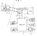
- Fig. 1 is the general system construction view of a keyless engine starting system including the steering lock module 9.
- the steering lock module 9 is composed of a control part 15 including a microcomputer, the knob switch 10, the seat unlocking switch 11, and a solenoid 16 for unlocking a lock to prevent the knob switch 10 from turning.
- a transmitting antenna 17 and a receiving unit 18 for conducting communication with a remote key 100, a fuel injection control unit (hereinafter referred to as "ECU") 19, and an actuator 20 for unlocking the seat locking device 14 are connected to the control part 15.
- an LED 21 for indicating the unlocking of the steering lock can be connected to the control part 15.
- the indicator LED 21 can be provided, for example, on the panel 4.
- the remote key 100 has a push button 22, an indicator lamp 23, and an indicator lamp 24. It is recommended that the indicator lamp 23 and the indicator lamp 24 be constructed of LEDs. The functions of the indicator lamp 23 and the indicator lamp 24 will be later described.
- Fig. 2 is a block diagram to show the construction of the remote key 100.
- the remote key 100 has a communication function of conducting communication with the steering lock module 9 to transmit ID information to the steering lock module 9.
- the remote key 100 includes a receiver circuit 26 to which a plurality of antennas 25-1, 25-2, 25-3 for allowing non-directional transmission and receiver are connected, a transmission circuit 27, and an indicator lamp drive circuit 28 for driving the indictor lamp (green LED) 23 and the indicator lamp (red LED) 24, an EEPROM 29 as a storage device for storing various kinds of data, and a CPU 30 for controlling these constituent elements.
- the remote key 100 is driven by a built-in power source 31.
- the power source 31 is, for example, a lithium battery. Signals correspond to the state of the push button 22 are inputted to the CPU 30.
- the CPU 30 has a function of allowing or not-allowing receiver from the steering module 9 in response to the state of the push button 22. In other words, by operating the push button 22 in a predetermined manner, the CPU 30 can be made to respond to or neglect a transmission signal from the steering lock module 9.
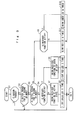
- Fig. 3 is a flow chart to show the processing of the CPU 30 based on the operation of the push button 22.
- step S1 it is determined at step S1 whether or not the push button 22 is pushed and if this determination result is affirmative, the sequence proceeds to step S2.
- step S2 It is determined at step S2 whether or not the push button 22 is pushed continuously for a first predetermined time T (for example, 0.1 second) or more. If this determination result is affirmative, it is determined that the operation of the push button 22 is an instantaneous operation, that is, a short time period push operation, and the sequence proceeds to step S3. It is determined that an operation performed for a time shorter than the time T is an error and the sequence passes this flow of process.
- T for example, 0.1 second
- step S3 It is determined at step S3 whether or not the push button 22 is pushed continuously for a second predetermined time T1 (T1 > T: for example, 1 second) or more. If this determination result is affirmative, it is determined that the operation of the push button 22 is a long-time operation (a long push) and the sequence proceeds to step S4.
- step S4 It is determined at step S4 whether or not the present state of the receiver circuit 26 of the remote key 100 is active, that is, in a standby state of receiver. If the state of the receiver circuit 26 is active, the sequence proceeds to step S5 where the receiver circuit 26 is brought to a state of stop, that is, a state in which function is stopped. To show that the receiver circuit 26 is brought to the state in which function is stopped, the sequence proceeds to step S6 where the red LED 24 is lit. Here, the state of illumination of this red LED 24 is finished in a predetermined short time, that is, the red LED 24 is lit only instantaneously.
- step S4 the sequence proceeds to step S7 where the receiver circuit 26 is brought to an active state, that is, a standby state of receiver.
- step S8 the green LED 23 is lit.
- the state of illumination of this green LED 23 is finished in a predetermined short time, that is, the green LED 23 is lit only instantaneously.
- step S9 it is determined whether or not the receiver circuit 26 is in the standby state of receiver. If the determination result at step S9 is affirmative, the sequence proceeds to step S10 where the green LED 23 is blinked to show that the receiver circuit 26 is in the standby state of receiver. The number of blinks is set at, for example, four. If the determination result at step S9 is negative, the sequence proceeds to step S11 where the red LED 24 is blinked to show that the receiver circuit 26 is in the state in which function is stopped. The number of blinks is set at, for example, four.
- Fig. 4 is a block diagram to summarize the processings in Fig. 3.
- the operation is neglected and regarded as an error and if the push button 22 is operated for a short time, the operation is regarded as an intentional operation, which can be recognized by the indicator lamp showing the present state of the receiver circuit 26. Further, if the push button 22 is pushed for a long time, the receiver circuit 26 is switched between the state in which function is stopped and the standby state of receiver, and this switching of the receiver circuit 26 is indicated.
- the receiver circuit 26 can be brought to the state of stop: firstly, the power of the receiver circuit 26 is turned off; secondly, even if receiver is conducted, the CPU 30 is not started, that is, is not brought to a run mode; and thirdly, even if the CPU 30 is started, the CPU 30 is not made to perform a processing of checking ID information.
- the keyless engine starting system shown in Fig. 1 when the push button 22 is operated to make the receiver circuit 26 of the remote key 100 active and a driver comes into a verification area with the remote key 100, the entire system operates. When the receiver circuit 26 is in the state of stop, the system does not operate. Hence, when the driver goes out of the verification area with the remote key 100, the keyless engine starting system is in an initial state in which each lock device is locked.
- Fig. 5 shows one example of the knob switch 10.
- the knob switch 10 in the initial state, the knob switch 10 is at a lock position. In this state, the knob switch 10 is locked and can be pushed but can not be turned.
- communication with the remote key 100 is started and ID information is checked and if the ID information is verified, the knob switch 10 can be turned.
- the knob switch 10 is turned to an ON position, communication is conducted with the ECU 19 and the ID information is checked between the ECU 19 and the handle lock module 9. If the ID information is verified, the steering lock is unlocked and the engine is brought to a state in which it is allowed to start and a function of the switch 11 for unlocking the seat lock device 14 is also made active.
- knob switch 10 When the knob switch 10 is turned to a starting position (ignition), operations of starting the engine, that is, the driving of a motor for starting the engine, the injecting of fuel, and igniting operation are started. In place of setting the knob switch 10 at the starting position, it is also recommended that another starting switch be provided. For example, another starting switch can be provided near the grip of the handlebar 2.
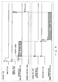
- Fig. 6 is a timing chart to show the operation of the keyless engine starting system. The general operation of the keyless engine starting system will be described with reference to Fig. 1 and Fig. 6.
- the control part 15 starts. Then, the control part 15 outputs a startup signal at a timing t1 and transmits ID information at a timing t2.
- the receiver circuit 26 of the remote key 100 starts in response to the startup signal of the control part 15 and the CPU 30 also starts at the same time.
- the remote key 100 receiving the ID information before a timing t3 transmits the ID information at a timing t4 .
- the control part 15 checks the transmitted ID information against the received ID information and if the ID information is verified, the solenoid 16 is operated at a timing t5 to stop preventing the knob switch 10 from turning. When preventing the knob switch 10 from turning is stopped, the seat unlocking switch 11 is brought to an operable state and when this seat unlocking switch 11 is pushed, the solenoid 20 for unlocking the seat locking device 14 is operated.
- the push button 22 is used to switch the state of the receiver circuit 26 of the remote key 100, but in place of this push button 22, for example, a switch for sliding a knob between an ON position and an OFF position can be used. This sliding switch can be easily recognized from the front and the side.
- the receiver circuit 26 receives the ID information after the push button 22 is pushed for a long time when the receiver circuit is active, in place of stopping the function of the receiver circuit, data different from the predetermined ID information can be transmitted back. This is because even if the vehicle-mounted unit 1 receives the data different from the predetermined ID information, the vehicle-mounted unit 1 does not bring the knob switch 10 to an operable state.
- the invention can be used not only for the above-described motorcycle but also for a wide variety of vehicles in which knob switches are not covered such as four-wheel vehicle, agriculture machine, and construction machine.
- the knob switch is not limited to this embodiment. In short, any switch can be used if it can be used as a switch for a keyless engine starting device.
Abstract
Description
- The invention relates to a remote controlling key (hereinafter referred to as "remote key") for a vehicle and in particular, to a remote key suitable for a vehicle starting system capable of unlocking the lock of a vehicle by short-distance wireless communication.
- A keyless entry system for a four-wheel automobile has been known in which when a person who has an exclusively designed remote key (forexample, a card key having a wireless communication function) comes near to a locked vehicle and enters a predetermined verification area, a door is unlocked and an engine is brought to a state of being ready to start. In this keyless entry system, when the person goes away from the vehicle with the card key, the door is locked and the engine cannot be started. This keyless entry system is disclosed in, for example, Japanese Unexamined Patent Publication No. 10-317754.
- A keyless entry system that has a normal mode of transmitting a remote control signal to a vehicle side to prevent a malfunction in the control of the system or to reduce the consumption of a battery and a transmission output stop mode of stopping the output of the remote control signal has been known (Japanese Unexamined Patent Publication No. 2003-64918).
[Patent document 1] JP 10-317754 A
[Patent document 2] JP 2003-64918 A - In a four-wheel automobile having doors, even if an engine is brought to a state of being ready to start by the function of a remote key, an engine startup operating procedure including steps of opening the door first and then, for example, of pushing a knob needs to be performed. Hence, even if an operation of unlocking a lock and an operation of bringing the engine to a state of being ready to start are performed on the vehicle side by conducting communication with the remote key, a preparatory operation for starting the engine can not be performed without the intentional operation of a remote key possessor, that is, a driver.
- However, in a motorcycle having no door, an engine startup operation can be performed only by a driver coming near to the vehicle with a remote key. Hence, even if the driver does not intend to start the engine, a preparatory operation for starting the engine can be performed immediately when the remote key comes near to the vehicle. For example, when the driver comes near to the vehicle to wash or maintain the vehicle, a preparation for starting the engine is started. To be specific, an engine start operating knob is unlocked.
- The object of the invention is to provide, in a keyless engine starting system, a remote key for a vehicle that can prevent a preparation of starting an engine from being started unless a driver performs an operation of starting the engine.
- The first feature of the present invention that a remote controlling key for a vehicle of the type in which identification information is transmitted in response to a startup signal from the vehicle in a verification area set for the vehicle to bring an engine starting switch provided in the vehicle to an operable state, the remote controlling key comprising: switching means for stopping or activating a function of transmission/receiver means that receives the startup signal and transmits the identification information.
- The second feature of the present invention that further comprising indicating means for indicating a state where the function of the transmission/receiver means is stopped and a state where the function of the transmission/receiver means is activated.
- The third feature of the present invention that wherein the indicating means is so constructed as to indicate.a state of the transmission/receiver means when the switching means is operated continuously for a first time period, and wherein the switching means is so constructed as to switch the function of the transmission/receiver means when it is operated continuously for a second time period longer than the first time period.
- According to the invention having the above features, it is possible to stop the function of the transmission/receiver means of the remote key or to activate the function, that is, to bring the transmission/receiver means into a state capable of conducting communication, by means of the switching means. With this, in a case where a driver does not intend to start the engine, even if the driver comes into a verification area with a remote key, the keyless engine starting system does not operate. When the driver does not drive the vehicle for a long time, the driver can stop the function of the transmission/receiver means to prevent the electricity consumption of the power source within the remote key. It is possible to recognize, by means of indicating means, whether or not the transmission/receiver function of the remote key is stopped.
- According to the third feature, if the switching means is not pushed for relatively a long time, the function of the transmission/receiver means of the remote key is not switched, so that it is possible to switch the state of the transmission/receiver means on the basis of a intentional operation.
-
- Fig. 1 is a general block diagram of a keyless engine starting system in accordance with one embodiment of the invention.
- Fig. 2 is a block diagram to show the construction of a remote key.
- Fig. 3 is a flow chart to show a processing in the remote key based on the operation of a push button.
- Fig. 4 is a schematic view to show the outline of a processing of the remote key.
- Fig. 5 is an external view of a knob switch.
- Fig. 6 is an operating timing chart of the keyless engine starting system.
- Fig. 7 is a perspective view of a motorcycle to which the remote key of the invention is applied.
- 9- handle lock module, 10- engine starting switch (knob switch), 15- controlpart, 22-pushbutton, 23, 24- indicator lamp, 26- receiver circuit, 100- remote key
- One embodiment of the invention will be described with reference to the drawings. Fig. 7 is an external perspective view of a scooter type motorcycle to which a keyless engine starting system in accordance with one embodiment of the invention is applied. In the drawing, a steering handle, that is, a
handlebar 2 turnably supported by a vehicle frame (not shown) is arranged on the front portion of thescooter type motorcycle 1 . The periphery of the base of thehandlebar 2 is covered with apanel 4 in whichinstruments 3 are arranged. Thepanel 4 is connected to afloor part 6 via alongitudinal panel 5. The front portion of the panel 4 (front side of a vehicle) is covered with afront cowl 8 having a headlamp (not shown) and turnsignal lamps 7. Asteering lock module 9 is housed in a space covered with thepanel 4 and thefront cowl 8. Thesteering lock module 9 has an engine starting switch (hereinafter referred to as "knob switch") 10 whose operating portion, that is, knob is exposed to thepanel 4. Thesteering lockmodule 9 alsohas amechanism that engages a lock bar driven by the operation of thisknob switch 10 with a lock hole formed in the shaft of thehandlebar 2 to make thehandlebar 2 unable to turn, and aseat unlocking switch 11. As the concrete structure of the steering lock can be adopted, for example, a structure disclosed in Japanese Unexamined Patent Publication No. 9-301239. - The
floor part 6 is further connected to arear cowl 12. Aseat 13 is disposed on the top of therear cowl 12. Theseat 13 also serves as a lid for covering a storage box of a helmet and the like and a fuel tank (both not shown) that are covered with therear cowl 12. Theseat 13 is freely opened or closed so as to perform a function as a lid and has an electrically operatedlocking device 14 operated by a solenoid. - Fig. 1 is the general system construction view of a keyless engine starting system including the
steering lock module 9. Thesteering lock module 9 is composed of acontrol part 15 including a microcomputer, theknob switch 10, theseat unlocking switch 11, and asolenoid 16 for unlocking a lock to prevent theknob switch 10 from turning. A transmittingantenna 17 and a receivingunit 18 for conducting communication with aremote key 100, a fuel injection control unit (hereinafter referred to as "ECU") 19, and anactuator 20 for unlocking theseat locking device 14 are connected to thecontrol part 15. Further, anLED 21 for indicating the unlocking of the steering lock can be connected to thecontrol part 15. Theindicator LED 21 can be provided, for example, on thepanel 4. - The
remote key 100 has apush button 22, anindicator lamp 23, and anindicator lamp 24. It is recommended that theindicator lamp 23 and theindicator lamp 24 be constructed of LEDs. The functions of theindicator lamp 23 and theindicator lamp 24 will be later described. - Fig. 2 is a block diagram to show the construction of the
remote key 100. Theremote key 100 has a communication function of conducting communication with thesteering lock module 9 to transmit ID information to thesteering lock module 9. Theremote key 100 includes areceiver circuit 26 to which a plurality of antennas 25-1, 25-2, 25-3 for allowing non-directional transmission and receiver are connected, atransmission circuit 27, and an indicatorlamp drive circuit 28 for driving the indictor lamp (green LED) 23 and the indicator lamp (red LED) 24, anEEPROM 29 as a storage device for storing various kinds of data, and aCPU 30 for controlling these constituent elements. Theremote key 100 is driven by a built-inpower source 31. Thepower source 31 is, for example, a lithium battery. Signals correspond to the state of thepush button 22 are inputted to theCPU 30. - The
CPU 30 has a function of allowing or not-allowing receiver from thesteering module 9 in response to the state of thepush button 22. In other words, by operating thepush button 22 in a predetermined manner, theCPU 30 can be made to respond to or neglect a transmission signal from thesteering lock module 9. - Fig. 3 is a flow chart to show the processing of the
CPU 30 based on the operation of thepush button 22. In Fig. 3, it is determined at step S1 whether or not thepush button 22 is pushed and if this determination result is affirmative, the sequence proceeds to step S2. It is determined at step S2 whether or not thepush button 22 is pushed continuously for a first predetermined time T (for example, 0.1 second) or more. If this determination result is affirmative, it is determined that the operation of thepush button 22 is an instantaneous operation, that is, a short time period push operation, and the sequence proceeds to step S3. It is determined that an operation performed for a time shorter than the time T is an error and the sequence passes this flow of process. It is determined at step S3 whether or not thepush button 22 is pushed continuously for a second predetermined time T1 (T1 > T: for example, 1 second) or more. If this determination result is affirmative, it is determined that the operation of thepush button 22 is a long-time operation (a long push) and the sequence proceeds to step S4. - It is determined at step S4 whether or not the present state of the
receiver circuit 26 of theremote key 100 is active, that is, in a standby state of receiver. If the state of thereceiver circuit 26 is active, the sequence proceeds to step S5 where thereceiver circuit 26 is brought to a state of stop, that is, a state in which function is stopped. To show that thereceiver circuit 26 is brought to the state in which function is stopped, the sequence proceeds to step S6 where thered LED 24 is lit. Here, the state of illumination of thisred LED 24 is finished in a predetermined short time, that is, thered LED 24 is lit only instantaneously. - On the other hand, if the determined result at step S4 is negative, the sequence proceeds to step S7 where the
receiver circuit 26 is brought to an active state, that is, a standby state of receiver. To show that thereceiver circuit 26 is brought to the standby state of receiver, the sequence proceeds to step S8 where thegreen LED 23 is lit. Here, the state of illumination of thisgreen LED 23 is finished in a predetermined short time, that is, thegreen LED 23 is lit only instantaneously. - If the determination result at step S3 is negative, that is, if the operation of the
push button 22 is a short-time operation that is not elongated to a long push, the sequence proceeds to step S9 where it is determined whether or not thereceiver circuit 26 is in the standby state of receiver. If the determination result at step S9 is affirmative, the sequence proceeds to step S10 where thegreen LED 23 is blinked to show that thereceiver circuit 26 is in the standby state of receiver. The number of blinks is set at, for example, four. If the determination result at step S9 is negative, the sequence proceeds to step S11 where thered LED 24 is blinked to show that thereceiver circuit 26 is in the state in which function is stopped. The number of blinks is set at, for example, four. - Fig. 4 is a block diagram to summarize the processings in Fig. 3. As shown in the drawing, in a case where the
push button 22 is operated only instantaneously (for example, less than 0.1 second) by mistake, the operation is neglected and regarded as an error and if thepush button 22 is operated for a short time, the operation is regarded as an intentional operation, which can be recognized by the indicator lamp showing the present state of thereceiver circuit 26. Further, if thepush button 22 is pushed for a long time, thereceiver circuit 26 is switched between the state in which function is stopped and the standby state of receiver, and this switching of thereceiver circuit 26 is indicated. - If any one of the following processings is performed, the
receiver circuit 26 can be brought to the state of stop: firstly, the power of thereceiver circuit 26 is turned off; secondly, even if receiver is conducted, theCPU 30 is not started, that is, is not brought to a run mode; and thirdly, even if theCPU 30 is started, theCPU 30 is not made to perform a processing of checking ID information. - In the keyless engine starting system shown in Fig. 1, when the
push button 22 is operated to make thereceiver circuit 26 of theremote key 100 active and a driver comes into a verification area with theremote key 100, the entire system operates. When thereceiver circuit 26 is in the state of stop, the system does not operate. Hence, when the driver goes out of the verification area with theremote key 100, the keyless engine starting system is in an initial state in which each lock device is locked. - Fig. 5 shows one example of the
knob switch 10. In Fig. 5, in the initial state, theknob switch 10 is at a lock position. In this state, theknob switch 10 is locked and can be pushed but can not be turned. When theknob switch 10 is pushed, communication with theremote key 100 is started and ID information is checked and if the ID information is verified, theknob switch 10 can be turned. When theknob switch 10 is turned to an ON position, communication is conducted with theECU 19 and the ID information is checked between theECU 19 and thehandle lock module 9. If the ID information is verified, the steering lock is unlocked and the engine is brought to a state in which it is allowed to start and a function of theswitch 11 for unlocking theseat lock device 14 is also made active. When theknob switch 10 is turned to a starting position (ignition), operations of starting the engine, that is, the driving of a motor for starting the engine, the injecting of fuel, and igniting operation are started. In place of setting theknob switch 10 at the starting position, it is also recommended that another starting switch be provided. For example, another starting switch can be provided near the grip of thehandlebar 2. - Fig. 6 is a timing chart to show the operation of the keyless engine starting system. The general operation of the keyless engine starting system will be described with reference to Fig. 1 and Fig. 6. First, when the
knob switch 10 is pushed at a timing t0, thecontrol part 15 starts. Then, thecontrol part 15 outputs a startup signal at a timing t1 and transmits ID information at a timing t2. - The
receiver circuit 26 of the remote key 100 starts in response to the startup signal of thecontrol part 15 and theCPU 30 also starts at the same time. Theremote key 100 receiving the ID information before a timing t3 transmits the ID information at a timing t4 . Thecontrol part 15 checks the transmitted ID information against the received ID information and if the ID information is verified, thesolenoid 16 is operated at a timing t5 to stop preventing theknob switch 10 from turning. When preventing theknob switch 10 from turning is stopped, theseat unlocking switch 11 is brought to an operable state and when thisseat unlocking switch 11 is pushed, thesolenoid 20 for unlocking theseat locking device 14 is operated. - In this embodiment, the
push button 22 is used to switch the state of thereceiver circuit 26 of theremote key 100, but in place of thispush button 22, for example, a switch for sliding a knob between an ON position and an OFF position can be used. This sliding switch can be easily recognized from the front and the side. - In a case where the
receiver circuit 26 receives the ID information after thepush button 22 is pushed for a long time when the receiver circuit is active, in place of stopping the function of the receiver circuit, data different from the predetermined ID information can be transmitted back. This is because even if the vehicle-mountedunit 1 receives the data different from the predetermined ID information, the vehicle-mountedunit 1 does not bring theknob switch 10 to an operable state. - The invention can be used not only for the above-described motorcycle but also for a wide variety of vehicles in which knob switches are not covered such as four-wheel vehicle, agriculture machine, and construction machine. The knob switch is not limited to this embodiment. In short, any switch can be used if it can be used as a switch for a keyless engine starting device.
Claims (5)
- A remote controlling key for a vehicle of the type in which identification information is transmitted in response to a startup signal from the vehicle in a verification area set for the vehicle to bring an engine starting switch provided in the vehicle to an operable state, the remote controlling key comprising:switching means for stopping or activating a function of transmission/receiver means that receives the startup signal and transmits the identification information.
- The remote controlling key for a vehicle as claimed in claim 1, further comprising indicating means for indicating a state where the function of the transmission/receiver means has been stopped and a state where the function of the transmission/receiver means has been activated.
- The remote controlling key for a vehicle as claimed in claim 2, wherein the indicating means is so constructed as to indicate a state of the transmission/receiver means when the switching means is operated continuously for a first period, and wherein the switching means is so constructed as to switch the function of the transmission/receiver means when it is operated continuously for a second period longer than the first time period.
- The remote controlling key for a vehicle as claimed in claim 1, wherein the vehicle is a scooter type motorcycle.
- The remote controlling key for a vehicle as claimed in claim 2, wherein the indicating means is comprised of a couple of LED lamps, where one of the lamps illuminates in one color to indicate function stopping state of the transmission/receiver means and the an other lamps illuminates in another color to indicate function activate state of the transmission/receiver means.
Applications Claiming Priority (2)
| Application Number | Priority Date | Filing Date | Title |
|---|---|---|---|
| JP2003337339A JP4100568B2 (en) | 2003-09-29 | 2003-09-29 | Vehicle remote key |
| PCT/JP2004/012254 WO2005030541A1 (en) | 2003-09-29 | 2004-08-26 | Remote control key for vehicle |
Publications (3)
| Publication Number | Publication Date |
|---|---|
| EP1669264A1 true EP1669264A1 (en) | 2006-06-14 |
| EP1669264A4 EP1669264A4 (en) | 2010-03-10 |
| EP1669264B1 EP1669264B1 (en) | 2012-03-28 |
Family
ID=34386123
Family Applications (1)
| Application Number | Title | Priority Date | Filing Date |
|---|---|---|---|
| EP20040772210 Expired - Fee Related EP1669264B1 (en) | 2003-09-29 | 2004-08-26 | Remote control key for vehicle |
Country Status (11)
| Country | Link |
|---|---|
| EP (1) | EP1669264B1 (en) |
| JP (1) | JP4100568B2 (en) |
| KR (1) | KR100780020B1 (en) |
| CN (1) | CN100486841C (en) |
| AR (1) | AR047220A1 (en) |
| BR (1) | BRPI0414835B1 (en) |
| CA (1) | CA2540192C (en) |
| ES (1) | ES2384877T3 (en) |
| MX (1) | MXPA06003294A (en) |
| TW (1) | TWI261561B (en) |
| WO (1) | WO2005030541A1 (en) |
Cited By (8)
| Publication number | Priority date | Publication date | Assignee | Title |
|---|---|---|---|---|
| EP1886885A2 (en) * | 2006-08-01 | 2008-02-13 | Yamaha Hatsudoki Kabushiki Kaisha | Vehicle control apparatus and vehicle provided with the same |
| WO2008031644A1 (en) * | 2006-09-15 | 2008-03-20 | Honeywell Technologies Sarl | Controller having a second control unit which can be activated by pressing a button |
| EP1970266A1 (en) * | 2007-03-15 | 2008-09-17 | Yamaha Hatsudoki Kabushiki Kaisha | Keyless entry system |
| US8400267B2 (en) | 2008-10-16 | 2013-03-19 | Omron Corporation | Vehicle authentication device |
| WO2019158356A1 (en) * | 2018-02-13 | 2019-08-22 | Bayerische Motoren Werke Aktiengesellschaft | Transmission for a motorcycle, and motorcycle comprising such a transmission |
| US10448628B2 (en) | 2017-03-27 | 2019-10-22 | Cnh Industrial America Llc | Electronic start system for an agricultural machine |
| US10510097B2 (en) | 2011-10-19 | 2019-12-17 | Firstface Co., Ltd. | Activating display and performing additional function in mobile terminal with one-time user input |
| EP3626548A1 (en) * | 2018-09-18 | 2020-03-25 | Gogoro Inc. | Methods for locking and/or unlocking electric vehicle and associated apparatus |
Families Citing this family (20)
| Publication number | Priority date | Publication date | Assignee | Title |
|---|---|---|---|---|
| ITRM20070191A1 (en) | 2006-04-06 | 2007-10-07 | Suzuki Motor Corp | ELECTRONIC AUTHENTICATION SYSTEM FOR MOTORCYCLE |
| JP4797758B2 (en) * | 2006-04-06 | 2011-10-19 | スズキ株式会社 | Electronic authentication system for motorcycles |
| KR100771777B1 (en) * | 2006-11-22 | 2007-10-30 | 주식회사 신창전기 | Romote key for vehicle |
| CN101135212B (en) * | 2007-10-19 | 2010-09-01 | 张卓 | Automobile key inverse-locking protection method and system |
| TWI392788B (en) * | 2009-03-24 | 2013-04-11 | Icm Inc | The method used to check the serial number of the data gateway |
| JP5155242B2 (en) * | 2009-04-20 | 2013-03-06 | アルプス電気株式会社 | Vehicle engine start system |
| US8725315B2 (en) * | 2010-12-17 | 2014-05-13 | GM Global Technology Operations LLC | Bi-directional VHF UHF polling mechanisms for intelligent PEPS polling |
| KR101877985B1 (en) * | 2011-08-23 | 2018-08-10 | 현대자동차주식회사 | System and method for remote open/close for vehicle and remote control therefor |
| TWI492868B (en) * | 2012-04-03 | 2015-07-21 | Hon Hai Prec Ind Co Ltd | Key fob and vehicle remote control system using the same |
| CN104424779B (en) * | 2013-08-30 | 2017-12-12 | 比亚迪股份有限公司 | System, the method for vehicle are controlled by mobile terminal |
| CN103738293A (en) * | 2014-01-13 | 2014-04-23 | 徐一丁 | One-way automobile remote control with locking memory function |
| US10127749B2 (en) * | 2016-01-11 | 2018-11-13 | Ford Global Technologies, Llc | System and method for profile indication on a key fob |
| JP6759647B2 (en) * | 2016-03-22 | 2020-09-23 | 株式会社タダノ | Remote control terminal anti-theft system |
| JP6693327B2 (en) * | 2016-08-02 | 2020-05-13 | トヨタ自動車株式会社 | Vehicle control device |
| JP7178010B2 (en) * | 2017-10-11 | 2022-11-25 | 朝日電装株式会社 | wireless communication system |
| WO2019198599A1 (en) | 2018-04-09 | 2019-10-17 | 本田技研工業株式会社 | Vehicle control system |
| CN111169410B (en) * | 2018-11-13 | 2023-02-03 | 上海汽车集团股份有限公司 | Remote control key long-press instruction identification method and vehicle body controller |
| JP2019048170A (en) * | 2018-12-12 | 2019-03-28 | パナソニックIpマネジメント株式会社 | Small-sized electric equipment and control device thereof |
| US11325562B1 (en) * | 2021-07-30 | 2022-05-10 | Geotab Inc. | Wire management module for a vehicle |
| CN114312666A (en) * | 2021-11-22 | 2022-04-12 | 江铃汽车股份有限公司 | Vehicle control method and device based on face recognition, storage medium and equipment |
Citations (3)
| Publication number | Priority date | Publication date | Assignee | Title |
|---|---|---|---|---|
| EP0823520A2 (en) * | 1996-08-08 | 1998-02-11 | Daimler-Benz Aktiengesellschaft | Authentication device with electronic authentication communication |
| EP0908589A2 (en) * | 1997-10-10 | 1999-04-14 | Robert Bosch Gmbh | Access system |
| EP1147953A2 (en) * | 2000-04-19 | 2001-10-24 | Texas Instruments Deutschland Gmbh | Security system to prevent unauthorised starting of the engine of a vehicle |
Family Cites Families (6)
| Publication number | Priority date | Publication date | Assignee | Title |
|---|---|---|---|---|
| JPH0667224U (en) * | 1993-03-09 | 1994-09-22 | セイコー電子工業株式会社 | Anti-theft device for motorcycles |
| JP3275777B2 (en) | 1997-05-19 | 2002-04-22 | トヨタ自動車株式会社 | Smart entry system |
| JP4335465B2 (en) * | 2001-02-14 | 2009-09-30 | 株式会社東海理化電機製作所 | Mobile device for remote control |
| JP2002320278A (en) * | 2001-04-23 | 2002-10-31 | Tokai Rika Co Ltd | Portable device for remote control |
| JP4530581B2 (en) * | 2001-06-18 | 2010-08-25 | 本田技研工業株式会社 | Remote lock control device for small vehicle and engine starting method for small vehicle |
| JP2003064918A (en) | 2001-08-24 | 2003-03-05 | Fuji Heavy Ind Ltd | Keyless entry system of automobile |
-
2003
- 2003-09-29 JP JP2003337339A patent/JP4100568B2/en not_active Expired - Lifetime
-
2004
- 2004-08-26 WO PCT/JP2004/012254 patent/WO2005030541A1/en active Application Filing
- 2004-08-26 ES ES04772210T patent/ES2384877T3/en active Active
- 2004-08-26 BR BRPI0414835A patent/BRPI0414835B1/en active IP Right Grant
- 2004-08-26 KR KR20067005838A patent/KR100780020B1/en not_active IP Right Cessation
- 2004-08-26 EP EP20040772210 patent/EP1669264B1/en not_active Expired - Fee Related
- 2004-08-26 CN CNB2004800282303A patent/CN100486841C/en active Active
- 2004-08-26 CA CA2540192A patent/CA2540192C/en not_active Expired - Fee Related
- 2004-08-26 MX MXPA06003294A patent/MXPA06003294A/en active IP Right Grant
- 2004-09-13 TW TW93127608A patent/TWI261561B/en not_active IP Right Cessation
- 2004-09-27 AR ARP040103484 patent/AR047220A1/en active IP Right Grant
Patent Citations (3)
| Publication number | Priority date | Publication date | Assignee | Title |
|---|---|---|---|---|
| EP0823520A2 (en) * | 1996-08-08 | 1998-02-11 | Daimler-Benz Aktiengesellschaft | Authentication device with electronic authentication communication |
| EP0908589A2 (en) * | 1997-10-10 | 1999-04-14 | Robert Bosch Gmbh | Access system |
| EP1147953A2 (en) * | 2000-04-19 | 2001-10-24 | Texas Instruments Deutschland Gmbh | Security system to prevent unauthorised starting of the engine of a vehicle |
Non-Patent Citations (1)
| Title |
|---|
| See also references of WO2005030541A1 * |
Cited By (14)
| Publication number | Priority date | Publication date | Assignee | Title |
|---|---|---|---|---|
| EP1886885A3 (en) * | 2006-08-01 | 2010-06-02 | Yamaha Hatsudoki Kabushiki Kaisha | Vehicle control apparatus and vehicle provided with the same |
| US8179237B2 (en) | 2006-08-01 | 2012-05-15 | Yamaha Hatsudoki Kabushiki Kaisha | Vehicle control apparatus and vehicle provided with the same |
| EP1886885A2 (en) * | 2006-08-01 | 2008-02-13 | Yamaha Hatsudoki Kabushiki Kaisha | Vehicle control apparatus and vehicle provided with the same |
| WO2008031644A1 (en) * | 2006-09-15 | 2008-03-20 | Honeywell Technologies Sarl | Controller having a second control unit which can be activated by pressing a button |
| EP1970266A1 (en) * | 2007-03-15 | 2008-09-17 | Yamaha Hatsudoki Kabushiki Kaisha | Keyless entry system |
| US8400267B2 (en) | 2008-10-16 | 2013-03-19 | Omron Corporation | Vehicle authentication device |
| US10896442B2 (en) | 2011-10-19 | 2021-01-19 | Firstface Co., Ltd. | Activating display and performing additional function in mobile terminal with one-time user input |
| US10510097B2 (en) | 2011-10-19 | 2019-12-17 | Firstface Co., Ltd. | Activating display and performing additional function in mobile terminal with one-time user input |
| US11551263B2 (en) | 2011-10-19 | 2023-01-10 | Firstface Co., Ltd. | Activating display and performing additional function in mobile terminal with one-time user input |
| US10448628B2 (en) | 2017-03-27 | 2019-10-22 | Cnh Industrial America Llc | Electronic start system for an agricultural machine |
| WO2019158356A1 (en) * | 2018-02-13 | 2019-08-22 | Bayerische Motoren Werke Aktiengesellschaft | Transmission for a motorcycle, and motorcycle comprising such a transmission |
| US11441679B2 (en) | 2018-02-13 | 2022-09-13 | Bayerische Motoren Werke Aktiengesellschaft | Transmission for a motorcycle, and motorcycle comprising such a transmission |
| US11377071B2 (en) | 2018-09-18 | 2022-07-05 | Gogoro Inc. | Methods for locking and/or unlocking electric vehicle and associated apparatus |
| EP3626548A1 (en) * | 2018-09-18 | 2020-03-25 | Gogoro Inc. | Methods for locking and/or unlocking electric vehicle and associated apparatus |
Also Published As
| Publication number | Publication date |
|---|---|
| BRPI0414835A (en) | 2006-11-21 |
| AR047220A1 (en) | 2006-01-11 |
| EP1669264B1 (en) | 2012-03-28 |
| CN1860052A (en) | 2006-11-08 |
| WO2005030541A1 (en) | 2005-04-07 |
| CA2540192A1 (en) | 2005-04-07 |
| JP4100568B2 (en) | 2008-06-11 |
| KR100780020B1 (en) | 2007-11-27 |
| CN100486841C (en) | 2009-05-13 |
| TW200517288A (en) | 2005-06-01 |
| JP2005104197A (en) | 2005-04-21 |
| BRPI0414835B1 (en) | 2015-12-08 |
| CA2540192C (en) | 2011-05-17 |
| KR20060095990A (en) | 2006-09-05 |
| ES2384877T3 (en) | 2012-07-13 |
| TWI261561B (en) | 2006-09-11 |
| EP1669264A4 (en) | 2010-03-10 |
| MXPA06003294A (en) | 2006-06-08 |
Similar Documents
| Publication | Publication Date | Title |
|---|---|---|
| CA2540192C (en) | Remote controlling key for vehicle | |
| EP1520757B1 (en) | Vehicle locking apparatus | |
| KR100756260B1 (en) | Anti-theft system for vehicle | |
| US7474199B2 (en) | In-vehicle device remote control system | |
| EP1574385B1 (en) | Passive entry system | |
| US7576636B2 (en) | Driver authorization system | |
| US7190255B2 (en) | Anti-theft device in motorcycle | |
| JPH07111702A (en) | Remote indicator of residual battery capacity of motor vehicle | |
| US6876292B2 (en) | Electronic key system for vehicle | |
| JPH0321575A (en) | Vehicle theft preventive device | |
| KR20080072551A (en) | Antitheft device for vehicle | |
| JP4094869B2 (en) | Engine start control device | |
| JP3799961B2 (en) | Electronic key device for vehicle | |
| JP3930386B2 (en) | Electronic key system | |
| US20030151873A1 (en) | Electronic key apparatus for vehicle and arrest cancellation method for rotation arresting device | |
| JP3520786B2 (en) | In-vehicle equipment remote control device | |
| EP2123521B1 (en) | Theft prevention systems for motorcycles | |
| JP2000264166A (en) | Starter controller for on-vehicle internal combustion engine | |
| JP3580530B2 (en) | Smart entry system for vehicles | |
| JP3831361B2 (en) | Operation control device of remote control system | |
| JP4479905B2 (en) | Door locking / unlocking control device | |
| JP3667272B2 (en) | Smart entry system for vehicle and control method thereof | |
| JP7445256B2 (en) | Vehicle wireless authentication system | |
| JP2004225471A (en) | Door lock control system | |
| JP2004175254A (en) | Vehicle key storage |
Legal Events
| Date | Code | Title | Description |
|---|---|---|---|
| PUAI | Public reference made under article 153(3) epc to a published international application that has entered the european phase |
Free format text: ORIGINAL CODE: 0009012 |
|
| 17P | Request for examination filed |
Effective date: 20060331 |
|
| AK | Designated contracting states |
Kind code of ref document: A1 Designated state(s): DE ES FR GB IT |
|
| DAX | Request for extension of the european patent (deleted) | ||
| RBV | Designated contracting states (corrected) |
Designated state(s): DE ES FR GB IT |
|
| A4 | Supplementary search report drawn up and despatched |
Effective date: 20100210 |
|
| 17Q | First examination report despatched |
Effective date: 20100730 |
|
| GRAP | Despatch of communication of intention to grant a patent |
Free format text: ORIGINAL CODE: EPIDOSNIGR1 |
|
| GRAS | Grant fee paid |
Free format text: ORIGINAL CODE: EPIDOSNIGR3 |
|
| GRAA | (expected) grant |
Free format text: ORIGINAL CODE: 0009210 |
|
| AK | Designated contracting states |
Kind code of ref document: B1 Designated state(s): DE ES FR GB IT |
|
| REG | Reference to a national code |
Ref country code: GB Ref legal event code: FG4D |
|
| RAP2 | Party data changed (patent owner data changed or rights of a patent transferred) |
Owner name: HONDALOCK MFG. CO., LTD. Owner name: HONDA MOTOR CO., LTD. |
|
| REG | Reference to a national code |
Ref country code: DE Ref legal event code: R096 Ref document number: 602004037120 Country of ref document: DE Effective date: 20120524 |
|
| REG | Reference to a national code |
Ref country code: ES Ref legal event code: FG2A Ref document number: 2384877 Country of ref document: ES Kind code of ref document: T3 Effective date: 20120713 |
|
| PLBE | No opposition filed within time limit |
Free format text: ORIGINAL CODE: 0009261 |
|
| STAA | Information on the status of an ep patent application or granted ep patent |
Free format text: STATUS: NO OPPOSITION FILED WITHIN TIME LIMIT |
|
| 26N | No opposition filed |
Effective date: 20130103 |
|
| REG | Reference to a national code |
Ref country code: DE Ref legal event code: R097 Ref document number: 602004037120 Country of ref document: DE Effective date: 20130103 |
|
| REG | Reference to a national code |
Ref country code: FR Ref legal event code: PLFP Year of fee payment: 13 |
|
| REG | Reference to a national code |
Ref country code: FR Ref legal event code: PLFP Year of fee payment: 14 |
|
| REG | Reference to a national code |
Ref country code: FR Ref legal event code: PLFP Year of fee payment: 15 |
|
| PGFP | Annual fee paid to national office [announced via postgrant information from national office to epo] |
Ref country code: FR Payment date: 20180712 Year of fee payment: 12 Ref country code: ES Payment date: 20180904 Year of fee payment: 15 |
|
| PGFP | Annual fee paid to national office [announced via postgrant information from national office to epo] |
Ref country code: GB Payment date: 20180822 Year of fee payment: 15 |
|
| PGFP | Annual fee paid to national office [announced via postgrant information from national office to epo] |
Ref country code: IT Payment date: 20190821 Year of fee payment: 16 Ref country code: DE Payment date: 20190813 Year of fee payment: 16 |
|
| GBPC | Gb: european patent ceased through non-payment of renewal fee |
Effective date: 20190826 |
|
| PG25 | Lapsed in a contracting state [announced via postgrant information from national office to epo] |
Ref country code: FR Free format text: LAPSE BECAUSE OF NON-PAYMENT OF DUE FEES Effective date: 20190831 |
|
| PG25 | Lapsed in a contracting state [announced via postgrant information from national office to epo] |
Ref country code: GB Free format text: LAPSE BECAUSE OF NON-PAYMENT OF DUE FEES Effective date: 20190826 |
|
| REG | Reference to a national code |
Ref country code: ES Ref legal event code: FD2A Effective date: 20210108 |
|
| PG25 | Lapsed in a contracting state [announced via postgrant information from national office to epo] |
Ref country code: ES Free format text: LAPSE BECAUSE OF NON-PAYMENT OF DUE FEES Effective date: 20190827 |
|
| REG | Reference to a national code |
Ref country code: DE Ref legal event code: R119 Ref document number: 602004037120 Country of ref document: DE |
|
| PG25 | Lapsed in a contracting state [announced via postgrant information from national office to epo] |
Ref country code: IT Free format text: LAPSE BECAUSE OF NON-PAYMENT OF DUE FEES Effective date: 20200826 Ref country code: DE Free format text: LAPSE BECAUSE OF NON-PAYMENT OF DUE FEES Effective date: 20210302 |