EP1583267B1 - Method for the time- and frequency-domain synchronisation of multiple devices in a transmission system with ofdm modulation - Google Patents
Method for the time- and frequency-domain synchronisation of multiple devices in a transmission system with ofdm modulation Download PDFInfo
- Publication number
- EP1583267B1 EP1583267B1 EP04700705A EP04700705A EP1583267B1 EP 1583267 B1 EP1583267 B1 EP 1583267B1 EP 04700705 A EP04700705 A EP 04700705A EP 04700705 A EP04700705 A EP 04700705A EP 1583267 B1 EP1583267 B1 EP 1583267B1
- Authority
- EP
- European Patent Office
- Prior art keywords
- frequency
- band
- correlation
- transmission system
- time
- Prior art date
- Legal status (The legal status is an assumption and is not a legal conclusion. Google has not performed a legal analysis and makes no representation as to the accuracy of the status listed.)
- Expired - Lifetime
Links
- 238000000034 method Methods 0.000 title claims description 60
- 230000005540 biological transmission Effects 0.000 title claims description 27
- 230000008569 process Effects 0.000 claims description 44
- 238000001514 detection method Methods 0.000 claims description 14
- 230000005611 electricity Effects 0.000 claims description 12
- 238000004891 communication Methods 0.000 claims description 11
- 238000000926 separation method Methods 0.000 claims description 8
- 238000004422 calculation algorithm Methods 0.000 claims description 7
- 238000012417 linear regression Methods 0.000 claims description 7
- 238000004364 calculation method Methods 0.000 claims description 6
- 238000007476 Maximum Likelihood Methods 0.000 claims description 2
- 230000015556 catabolic process Effects 0.000 claims description 2
- 125000004122 cyclic group Chemical group 0.000 claims description 2
- 239000000969 carrier Substances 0.000 description 5
- 230000008901 benefit Effects 0.000 description 3
- 238000000354 decomposition reaction Methods 0.000 description 3
- 230000006872 improvement Effects 0.000 description 3
- 230000001419 dependent effect Effects 0.000 description 2
- 230000003595 spectral effect Effects 0.000 description 2
- 238000007796 conventional method Methods 0.000 description 1
- 238000005516 engineering process Methods 0.000 description 1
- 238000001914 filtration Methods 0.000 description 1
- 238000012067 mathematical method Methods 0.000 description 1
- 230000009467 reduction Effects 0.000 description 1
- 230000004044 response Effects 0.000 description 1
- 230000011664 signaling Effects 0.000 description 1
- 230000001360 synchronised effect Effects 0.000 description 1
Images


Classifications
-
- H—ELECTRICITY
- H04—ELECTRIC COMMUNICATION TECHNIQUE
- H04L—TRANSMISSION OF DIGITAL INFORMATION, e.g. TELEGRAPHIC COMMUNICATION
- H04L27/00—Modulated-carrier systems
- H04L27/26—Systems using multi-frequency codes
- H04L27/2601—Multicarrier modulation systems
- H04L27/2647—Arrangements specific to the receiver only
- H04L27/2655—Synchronisation arrangements
- H04L27/2657—Carrier synchronisation
-
- H—ELECTRICITY
- H04—ELECTRIC COMMUNICATION TECHNIQUE
- H04L—TRANSMISSION OF DIGITAL INFORMATION, e.g. TELEGRAPHIC COMMUNICATION
- H04L27/00—Modulated-carrier systems
- H04L27/26—Systems using multi-frequency codes
- H04L27/2601—Multicarrier modulation systems
- H04L27/2626—Arrangements specific to the transmitter only
- H04L27/2627—Modulators
- H04L27/264—Pulse-shaped multi-carrier, i.e. not using rectangular window
- H04L27/26416—Filtering per subcarrier, e.g. filterbank multicarrier [FBMC]
-
- H—ELECTRICITY
- H04—ELECTRIC COMMUNICATION TECHNIQUE
- H04L—TRANSMISSION OF DIGITAL INFORMATION, e.g. TELEGRAPHIC COMMUNICATION
- H04L27/00—Modulated-carrier systems
- H04L27/26—Systems using multi-frequency codes
- H04L27/2601—Multicarrier modulation systems
- H04L27/2647—Arrangements specific to the receiver only
- H04L27/2649—Demodulators
- H04L27/26534—Pulse-shaped multi-carrier, i.e. not using rectangular window
- H04L27/2654—Filtering per subcarrier, e.g. filterbank multicarrier [FBMC]
-
- H—ELECTRICITY
- H04—ELECTRIC COMMUNICATION TECHNIQUE
- H04L—TRANSMISSION OF DIGITAL INFORMATION, e.g. TELEGRAPHIC COMMUNICATION
- H04L27/00—Modulated-carrier systems
- H04L27/26—Systems using multi-frequency codes
- H04L27/2601—Multicarrier modulation systems
- H04L27/2647—Arrangements specific to the receiver only
- H04L27/2655—Synchronisation arrangements
- H04L27/2662—Symbol synchronisation
-
- H—ELECTRICITY
- H04—ELECTRIC COMMUNICATION TECHNIQUE
- H04L—TRANSMISSION OF DIGITAL INFORMATION, e.g. TELEGRAPHIC COMMUNICATION
- H04L27/00—Modulated-carrier systems
- H04L27/26—Systems using multi-frequency codes
- H04L27/2601—Multicarrier modulation systems
- H04L27/2647—Arrangements specific to the receiver only
- H04L27/2655—Synchronisation arrangements
- H04L27/2668—Details of algorithms
- H04L27/2669—Details of algorithms characterised by the domain of operation
- H04L27/2671—Time domain
-
- H—ELECTRICITY
- H04—ELECTRIC COMMUNICATION TECHNIQUE
- H04L—TRANSMISSION OF DIGITAL INFORMATION, e.g. TELEGRAPHIC COMMUNICATION
- H04L27/00—Modulated-carrier systems
- H04L27/26—Systems using multi-frequency codes
- H04L27/2601—Multicarrier modulation systems
- H04L27/2647—Arrangements specific to the receiver only
- H04L27/2655—Synchronisation arrangements
- H04L27/2668—Details of algorithms
- H04L27/2669—Details of algorithms characterised by the domain of operation
- H04L27/2672—Frequency domain
-
- H—ELECTRICITY
- H04—ELECTRIC COMMUNICATION TECHNIQUE
- H04L—TRANSMISSION OF DIGITAL INFORMATION, e.g. TELEGRAPHIC COMMUNICATION
- H04L27/00—Modulated-carrier systems
- H04L27/26—Systems using multi-frequency codes
- H04L27/2601—Multicarrier modulation systems
- H04L27/2647—Arrangements specific to the receiver only
- H04L27/2655—Synchronisation arrangements
- H04L27/2668—Details of algorithms
- H04L27/2673—Details of algorithms characterised by synchronisation parameters
- H04L27/2675—Pilot or known symbols
Definitions
- the present invention refers to a process of synchronization in the time and frequency domain for multiple equipments in a transmission system using OFDM (orthogonal frequency division multiplexing) modulation.
- the objective of this process is to improve the estimation of the start of the OFDM symbols and the estimation of frequency error in the oscillators in various situations such as in channels with narrow band noise, frequency selective channels or channels in which noise power varies with frequency.
- the application of this process to synchronisation also as well as facilitating simultaneous estimation of frequency error in the analog traslation and frequency error in the system sample allows said estimations to be carried out in situations where the classic synchronisation processes do not achieve results.
- the results, in the form of average or weighted average can be combined to achieve more accurate estimations with a smaller deviation from the real value that one wants to estimate.
- synchronisation process it is necessary to carry out a synchronisation process in the majority of telecommunication systems so as to adequately obtain the information transmitted from the received signals to the channel.
- One or more types of synchronization are required depending on how the transmission is carried out and the modulation used.
- To transmit using OFDM modulation it is necessary to carry out synchronisation in time which consists of determining the start of the OFDM symbols in reception, and synchronization in frequency, so that frequency of the oscillators used for the sample or for the analog traslation of transmitted and received signal is sufficiently close.
- this invention consists of a process for synchronisation in the time and frequency domain for multiple equipments in a transmission system with OFDM modulation.
- This process is applicable to two-way communication applicable to two-way communication over the electricity network between different equipments connected to the same electricity network so as to provide an estimation of the start of the OFDM symbols in reception and the frequency error of the local oscillators in the equipments, and comprises the generation of synchronisation sequences that are transmitted over the electricity network.
- These synchronisation sequences are sent over the same channel used for the sending of data, said channel characterised by a connection between one equipment and all the other equipments.
- the process is characterized because it comprises the decomposition of the received signals made up of the synchronisation sequences and data in various frequency bands or ranges. Thereafter, the synchronisation sequences of each one of the frequency bands is detected by applying a synchronisation algorithm in time that allows the start of the OFDM symbol and frequency error in the local oscillators in each frequency band to be estimated, instead of the complete received signal which is the conventional method.
- the process allows improvement in the estimation of the start of the OFDM symbols and in the estimation of frequency error in the oscillators in the equipments in cases where narrow band noises are present in the channel, that is, ingress noise.
- it improves estimation of the start of the OFDM symbols and it improves frequency error in the case that the noise power added to the channel by the signal varies with frequency, that is, in case the channel includes coloured noise.
- Another of the advantages of this process is that it permits estimation of sample frequency error, that increases linearly with frequency and which cannot be estimated conventionally with the complete signal, and it improves estimation of frequency error in analog traslation with respect to the use of the complete received signal for the estimation of same.
- the process in this invention facilitates improving the results of the estimation of the start of the OFDM signal and the frequency error in case detection of the synchronisation sequence is achieved in more than one frequency band by means of combining the estimation obtained in each frequency and, by average or weighted average linear regression.
- break down of the received signal into frequency bands or ranges is carried out by applying a band pass filter centred in each one of the frequency bands, a frequency traslation in the filtered signals to work with each band in base band, and optionally, an decimator to simplify the complexity of the electronics necessary to detect the synchronisation sequence.
- Another way of carrying out this break down is to filter the synchronisation sequences simultaneously by means of uniform and decimated DFT (Discreet Fourier Transform) filters with the complexity of a prototype band pass filter, and a Discreet Fourier Transform (DFT).
- DFT Discreet Fourier Transform
- the breakdown or the synchronisation sequences may also be carried out directly by means of a Discreet Fourier Transform (DFT) circuit.
- DFT Discreet Fourier Transform
- detection of the synchronisation sequences takes place in each one of the frequency bands or ranges by means of maximizing the maximum likelihood known conventionally so that estimation of the start of the OFDM symbols is carried out from the calculation of the maximum time correlation of the samples in each band, and this maximum becomes the mid point in the flat zone for the correlation peak, whose size in number of samples is equal to the number of samples of the cyclic prefix without inter-symbol interference (ISI), and thereafter the angle of this correlation in the moment determined as maximum correlation is calculated in each one of the frequency bands so as to achieve an estimate of frequency error and adjust the oscillators to a common reference.
- ISI inter-symbol interference
- the correlation maximum is calculated by detecting the correlation peaks that surpass a power threshold in each one of the frequency bands or ranges in the received signal, and because the value of this threshold is fixed to minimize the probability of producing false alarms, and the correlation is calculated by means of the following algorithm:
- the power is calculated by means of the following algorithm:
- r i,d is the signal corresponding to the frequency corresponding to the ith in the moment d
- L is the number of samples in the half symbol
- Pi(d) is the correlation in the band ith in the moment d
- P i d P i ⁇ d - 1 + r i , d ⁇ r * i , d - L - r i , d - L ⁇ r * i , d - 2 ⁇ L
- R i d R i ⁇ d - 1 + 1 2 ⁇ r i , d 2 - 1 2 ⁇ r i , d - 2 ⁇ L 2
- P i (d) is the correlation in the frequency band ith in the moment d
- r i,x the signal corresponding to the ith band in the moment x.
- the moment of detection of the synchronisation sequences is taken to be the mid point of the zone that exceeds 90% of the maximum correlation while delaying an adequate number of samples to reduce interference between symbols to a minimum, and the number of samples is adjustable.
- Separating frequency bands improves the calculation of the frequency error in analog traslation by reducing variance when the averages or weighted averages of the error values calculated in each of the frequency bands is used.
- separating the frequency bands permits estimation of error in the sample frequency by means of linear regression of the values of the errors obtained in each band and said error value cannot be estimated conventionally using the full received signal since the error in sample frequency increases with frequency.
- the process in this invention may also be used when coexistence symbols are transmitted, these are detected in reception by means of band separation and detected in each one of these bands, with the objective of allowing the system to recognize if another has transmitted a certain sequence in the channel or not.
- All communication systems or at least a part of the communication system such as the synchronization block require a minimum signal to noise ratio (SNR) in order to be able to function, that is, it is necessary that the received signal has a certain value relative to the noise value on the line so that the system can carry out communication.
- SNR signal to noise ratio
- Minimum SNR cannot reach all the band width used by the system in communication systems with a frequency selective channel, or in systems where noise is dependent on frequency, or in both, due to existing channel attenuation or to the noise level, however it can reach some frequency ranges within the total band width.
- the process described in this invention takes advantage of this circumstance to calculate estimates and synchronisation in such scenarios.
- Figure 1 shows spectral density of signal power and noise at the receptor entrance in a certain situation.
- the filter banks are as complex as a prototype band pass filter (which as mentioned previously is located in each frequency band) and it is used with a DFT.
- Decomposition of the entry signal in M frequency bands occurs at the exit to the inverse Fourier transform (IDFT)3 and each of the frequency bands ahs a sample frequency M times less that that of the entry signal.
- M is also the number of points in the IDFT.
- each of the M signals is treated independently and the estimations are carried out for each one of these bands separately.
- the complexity is similar to that obtained on carrying the estimations for the original signal since we have M signals but the master frequency for each one has been divided by M.
- some of the bands (sub-bands) may be eliminated if they do not contain information and therefore the complexity is further reduced.
- the specifications for the prototype filter depend on the particular application for which the process described in this invention will be used. Some examples of such applications include estimation of signal parameters, the detection of coexistence signals or the detection of synchronism signals.
- each of the frequency bands into which the signal is divided one may apply any of the methods described in the state of the art and correct synchronization in one band is sufficient to begin the demodulation process in reception, depending on the type of modulation used.
- the result is a method of synchronisation with diversity in frequency, highly resistant to narrow band noises, channel selectivity and power noise dependent on frequency and which can function in typical channels including in those with SNR less that -10dB over the whole band.
- SNR in one of the frequency bands or ranges are sufficient to detect the synchronisation signal used in this band.
- this process can be applied along with the synchronisation method described in Spanish patent submission 200.101.121 concerning a "Process for downstream synchronisation of multiple users in a point to multipoint transmission system with OFDM modulation".
- the signal to be transmitted is the same as in said patent, that is to say, two identical synchronisation symbols, due to the fact that this property is maintained when the signal is decomposed in the frequency bands.
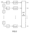
- a structure such as that shown in Figure 2 is placed in the receptor and thereafter the power and correlation metrics are calculated as in the patent mentioned above except that in this present case, the limits of all the sums are divided by M where M is the decimated value of the entry signal, or to put it another way, the number of bands.
- the synchronisation sequence is composed of only one synchronisation symbol divided into two equal halves.
- the information transmitted in the carriers used in the synchronisation symbols may be in fixed or psuedo-random sequence.
- the odd and even carriers in the OFDM symbols are set at zero so as to have the symmetry required in the synchronisation symbols.
- the properties of the synchronisation symbol, and more specifically its symmetry, is maintained when the bands are separated in reception and this allows us to have multiple synchronisation results which facilitate improving their precision.
- Any other type of synchronisation sequence (in relation to the number of symbols sent) and the method of detection may use the same method as described previously, only if the properties of the synchronisation symbol are maintained when band separation is carried out.
- sample frequency error may be calculated from the correlation angle in the optimum moment in the window, substituting f i for central frequency in the band (sub-band).
- ⁇ ⁇ f s / f s - ⁇ P i d iopt 2 ⁇ ⁇ ⁇ f i ⁇ K N / 2
- ⁇ (.) is the angle parameter, f i central frequency in the ith band, K the interpolation order or decimator and N the number of samples in the OFDM symbol.
- m is the result of linear regression of the estimates of the different band and ⁇ f s / f s sample frequency error.
- Another advantage of the process in this invention is that it offers the possibility to simultaneously calculate error in sample frequency and error in traslation to the analog band (error type 3), by carrying out linear regression of the errors measured in each band to calcualte the slope (sample frequency error) and the cross over with the vertical axis (analog traslation frequency error) as can be seen in figure 4.
- T s is the time of the symbol with cyclical prefix
- ⁇ f IQ is the error in frequency traslation in the analog band.
- Sample frequency error is obtained from m as in the case where only sample frequency error occurs.
- the process in this invention can also be used for coexistence signalling, that is the detection of signals used to implement a protocol for coexistence of various technologies over one transmission medium.
- coexistence signalling that is the detection of signals used to implement a protocol for coexistence of various technologies over one transmission medium.
- special signals that all systems must necessarily be capable of transmitting and receiving are used in order to implement an equitable medium access control, and must be detected even in conditions of very low SNR.
- transmission media such as the electricity network or radio there is the added problem that these systems can transmit simultaneously if attenuation between them is sufficient to have the signals of one arrive at the other below the noise level, thereby making them undetectable to each other.
- Coexistence signals serve to determine if two or more nodes (equipment that may belong to one or more different communication systems) may transmit simultaneously, depending on whether the signal of one node is receive by the other with more or less power than noise for each one of the frequencies used in the communication.
- the best option is to transmit various signals in different frequencies (the number of frequencies depending on frequency selectivity in the channel), which are independently detected in reception. Detection of one of these frequencies is sufficient to determine that one node is transmitting the coexistence signal.
- the structure shown in Figure 2 is used in reception.
- the modulation used in one of the systems that must coexist is OFDM it is enough that some of the carriers have sufficient SNR for the demodulation of these carriers to be correct thanks to the good behaviour of this type of modulation in these type of frequency selective channels. It is also possible to carry out detection even when SNR is average or negative, if the correct value can be obtained in one of the ranges in which the received signal has been divided. If a coexistence signal that occupies full band width is used to implement coexistence it may give rise to the fact that this signal will not be detected by a node that uses OFDM modulation and two nodes may simultaneously occupy the channel causing interference, since the signal of one will not be lower than the noise level detected in reception in all frequencies in the second node. According to what is described herein, the process in this invention solves this problem.
Landscapes
- Engineering & Computer Science (AREA)
- Computer Networks & Wireless Communication (AREA)
- Signal Processing (AREA)
- Synchronisation In Digital Transmission Systems (AREA)
- Noise Elimination (AREA)
- Mobile Radio Communication Systems (AREA)
- Transmitters (AREA)
Abstract
Description
- The present invention, as described herein refers to a process of synchronization in the time and frequency domain for multiple equipments in a transmission system using OFDM (orthogonal frequency division multiplexing) modulation. The objective of this process is to improve the estimation of the start of the OFDM symbols and the estimation of frequency error in the oscillators in various situations such as in channels with narrow band noise, frequency selective channels or channels in which noise power varies with frequency. The application of this process to synchronisation also as well as facilitating simultaneous estimation of frequency error in the analog traslation and frequency error in the system sample allows said estimations to be carried out in situations where the classic synchronisation processes do not achieve results.
- Furthermore, in cases where it is possible to carry out various estimations of these factors, the results, in the form of average or weighted average can be combined to achieve more accurate estimations with a smaller deviation from the real value that one wants to estimate.
- It is necessary to carry out a synchronisation process in the majority of telecommunication systems so as to adequately obtain the information transmitted from the received signals to the channel. One or more types of synchronization are required depending on how the transmission is carried out and the modulation used. In general, to transmit using OFDM modulation it is necessary to carry out synchronisation in time which consists of determining the start of the OFDM symbols in reception, and synchronization in frequency, so that frequency of the oscillators used for the sample or for the analog traslation of transmitted and received signal is sufficiently close.
- Many methods of synchronisation of OFDM signals are known in the state of the art but none of these are secure enough to avoid false indications of synchronisation in point to multipoint systems in which the electricity network is the transmission means used.
- It is well known that use of the electricity network as a transmission means is problematic for synchronisation since the connection-disconnection of various apparatus on the network produces tension peaks and impedance variation on the line causing channel response to vary in time. Impulsive noises, which are very usual in the electricity network affect synchronisation, in large part because by definition these are occasional noises that affect a small number of samples and therefore can impede adequate detection of the synchronisation sequences if they coincide in time with said sequences. Band separation as proposed in this patent, reduces the consequences of these noises so that it is possible to apply known synchronization methods, which due to the improvement proposed will offer optimum results in noisy environments such as the electricity network.
- Among the synchronisation methods in the state of the art those that particularly stand out are described in
US Patent No 5732113 which describes a process of time synchronisation that uses a single synchronisation symbol with two equal half symbols, and that described in Spanish patent submission200.101.121 - On the other hand, it is important to indicate that the filter banks such as those described in the book "Multirate Systems and Filters Banks", by P.P. Vaidyanathan, published by Prentice Hall in 1993, are known but that these filters have not been used for the division of synchronisation sequences received for independent detection in frequency bands such as described in this invention and which achieves the considerable improvement over the state of the art as described above.
- To achieve the objectives and avoid the inconveniencies described in previous paragraphs, this invention consists of a process for synchronisation in the time and frequency domain for multiple equipments in a transmission system with OFDM modulation.
This process is applicable to two-way communication applicable to two-way communication over the electricity network between different equipments connected to the same electricity network so as to provide an estimation of the start of the OFDM symbols in reception and the frequency error of the local oscillators in the equipments, and comprises the generation of synchronisation sequences that are transmitted over the electricity network. These synchronisation sequences are sent over the same channel used for the sending of data, said channel characterised by a connection between one equipment and all the other equipments. The process is characterized because it comprises the decomposition of the received signals made up of the synchronisation sequences and data in various frequency bands or ranges. Thereafter, the synchronisation sequences of each one of the frequency bands is detected by applying a synchronisation algorithm in time that allows the start of the OFDM symbol and frequency error in the local oscillators in each frequency band to be estimated, instead of the complete received signal which is the conventional method. - It is thanks to these characteristics that the process allows improvement in the estimation of the start of the OFDM symbols and in the estimation of frequency error in the oscillators in the equipments in cases where narrow band noises are present in the channel, that is, ingress noise. In case of transmission over a frequency selective channel it improves estimation of the start of the OFDM symbols and it improves frequency error in the case that the noise power added to the channel by the signal varies with frequency, that is, in case the channel includes coloured noise. Another of the advantages of this process is that it permits estimation of sample frequency error, that increases linearly with frequency and which cannot be estimated conventionally with the complete signal, and it improves estimation of frequency error in analog traslation with respect to the use of the complete received signal for the estimation of same. It also allows simultaneous estimation of frequency error in analog traslation and carries out the estimation of the start of the OFDM symbols as well as calculating frequency error in the sample when detected in two or more frequency bands or ranges including in cases where use of the complete signal does not produce a result. Finally, the process in this invention facilitates improving the results of the estimation of the start of the OFDM signal and the frequency error in case detection of the synchronisation sequence is achieved in more than one frequency band by means of combining the estimation obtained in each frequency and, by average or weighted average linear regression.
- In the process in this invention break down of the received signal into frequency bands or ranges is carried out by applying a band pass filter centred in each one of the frequency bands, a frequency traslation in the filtered signals to work with each band in base band, and optionally, an decimator to simplify the complexity of the electronics necessary to detect the synchronisation sequence.
- Another way of carrying out this break down is to filter the synchronisation sequences simultaneously by means of uniform and decimated DFT (Discreet Fourier Transform) filters with the complexity of a prototype band pass filter, and a Discreet Fourier Transform (DFT).
- In the same way, the breakdown or the synchronisation sequences may also be carried out directly by means of a Discreet Fourier Transform (DFT) circuit.
- In the process described in this invention, detection of the synchronisation sequences takes place in each one of the frequency bands or ranges by means of maximizing the maximum likelihood known conventionally so that estimation of the start of the OFDM symbols is carried out from the calculation of the maximum time correlation of the samples in each band, and this maximum becomes the mid point in the flat zone for the correlation peak, whose size in number of samples is equal to the number of samples of the cyclic prefix without inter-symbol interference (ISI), and thereafter the angle of this correlation in the moment determined as maximum correlation is calculated in each one of the frequency bands so as to achieve an estimate of frequency error and adjust the oscillators to a common reference.
- The correlation maximum is calculated by detecting the correlation peaks that surpass a power threshold in each one of the frequency bands or ranges in the received signal, and because the value of this threshold is fixed to minimize the probability of producing false alarms, and the correlation is calculated by means of the following algorithm:


- The calculation of correlation and power is undertaken iteratively, storing the samples and preferably the partial products to calculate the correlation and the power by means of the following algorithms:


- The moment of detection of the synchronisation sequences is taken to be the mid point of the zone that exceeds 90% of the maximum correlation while delaying an adequate number of samples to reduce interference between symbols to a minimum, and the number of samples is adjustable.
- On the other hand, because the real part of the correlation dominates the imaginary part it is possible to use only the real part of the correlation to simplify the calculation of the correlation in each frequency band or range if the frequency error is less than a certain threshold.
- To improve the results of the estimation of the start of the OFDM symbols in each frequency band one can combine these results as averages or weighted averages so that the final estimate will be more reliable and with less variance than that obtained using the complete received signal without separation in ranges.
- Separating frequency bands improves the calculation of the frequency error in analog traslation by reducing variance when the averages or weighted averages of the error values calculated in each of the frequency bands is used.
- Furthermore, separating the frequency bands permits estimation of error in the sample frequency by means of linear regression of the values of the errors obtained in each band and said error value cannot be estimated conventionally using the full received signal since the error in sample frequency increases with frequency.
- Finally, and thanks to the separation into bands, the error in analog frequency traslation and the error in sample frequency can be estimated simultaneously.
- On the other hand, the process in this invention may also be used when coexistence symbols are transmitted, these are detected in reception by means of band separation and detected in each one of these bands, with the objective of allowing the system to recognize if another has transmitted a certain sequence in the channel or not.
- The following drawings are provided to facilitate a better understanding of the present invention and while forming an integral part of the detailed description and the claims, they offer an illustrative but not limited representation of the principles of this invention.
-
-
Figure 1 .- Represents an example spectral density of signal power and noise in reception in a specific scenario. -
Figure 2 .- Graphically represents one of the means of carrying out division into frequency bands or ranges using uniform and decimated discreet Fourier transform (DFT) filters. -
Figure 3 .- Graphically represents a typical correlation scenario and the power multiplied by a threshold starting from the samples obtained in reception. - Figure 4.- Demonstrates the comportment of the error in the sample frequency and the error in the analog traslation frequency.
- This section provides a description of an example of one embodiment of the invention, referencing the numbering used in the drawings. The present invention is defined by the features of
claim 1. - All communication systems or at least a part of the communication system such as the synchronization block, require a minimum signal to noise ratio (SNR) in order to be able to function, that is, it is necessary that the received signal has a certain value relative to the noise value on the line so that the system can carry out communication. Minimum SNR cannot reach all the band width used by the system in communication systems with a frequency selective channel, or in systems where noise is dependent on frequency, or in both, due to existing channel attenuation or to the noise level, however it can reach some frequency ranges within the total band width. The process described in this invention takes advantage of this circumstance to calculate estimates and synchronisation in such scenarios.
Figure 1 shows spectral density of signal power and noise at the receptor entrance in a certain situation. In this case, average SNR over the total band is 0dB, which is not enough for communication, but it can be seen that in certain frequency ranges the power density of the signal is higher than the noise and therefore in these ranges communication will be possible. Due to the behaviour of the channel in such situations classic processes either cannot achieve synchronisation, or they only achieve it with very poor quality. This type of channel is very common in systems that use the electricity network as the transmission medium. The process described in this invention undertakes division into various frequency ranges (by means of filtering in reception) and works on each one these signal separately. In the majority of situations, synchronisation is necessary to transmit a specific signal in each one of the frequency bands, and being able to synchronize in any of the bands improves the results. It is not enough to transmit an OFDM signal due to a specific characteristic of this type of modulation whereby multiple carriers once separated can regroup in bands. To divide the signal into bands a band pass filter centred in each of the frequency bands can be applied. Furthermore, the signal must be demodulated to take it to base band and decimated because if this is not done the frequency in each band will be the same as that in the original signal and total complexity will be multiplied by the number of bands. All these operations can be carried out simultaneously and efficiently using uniform and decimated DTF (discreet Fourier transform) filter banks, which is a well know process in the state of the art. In this case, the filter banks are as complex as a prototype band pass filter (which as mentioned previously is located in each frequency band) and it is used with a DFT. This structure can be seen inFigure 2 where the filters Ei(z) correspond to the poly phase decomposition of the prototype filter where i=0, 1...M-1 where M is the number of bands in which the received signal x(n) is decomposed, 1 is a sample delay of (z-1) and 2 is a decimator for M. Decomposition of the entry signal in M frequency bands occurs at the exit to the inverse Fourier transform (IDFT)3 and each of the frequency bands ahs a sample frequency M times less that that of the entry signal. M is also the number of points in the IDFT. From this point in the system each of the M signals is treated independently and the estimations are carried out for each one of these bands separately. The complexity is similar to that obtained on carrying the estimations for the original signal since we have M signals but the master frequency for each one has been divided by M. Furthermore, some of the bands (sub-bands) may be eliminated if they do not contain information and therefore the complexity is further reduced. - The specifications for the prototype filter depend on the particular application for which the process described in this invention will be used. Some examples of such applications include estimation of signal parameters, the detection of coexistence signals or the detection of synchronism signals.
- Another of these applications is synchronisation in OFDM systems. The majority of synchronisation methods for OFDM signals use the signal in time to carry out this function and therefore they fail in situations such as that presented in
Figure 1 . - It is principally in such cases that use of the structure presented in
Figure 2 can improve the synchronisation. In each of the frequency bands into which the signal is divided one may apply any of the methods described in the state of the art and correct synchronization in one band is sufficient to begin the demodulation process in reception, depending on the type of modulation used. - When SNR is high enough so that various band synchronise then we have various estimations of the start of the symbol and frequency error simultaneously and therefore techniques such as combining results to improve the final estimation can be applied.
- The result is a method of synchronisation with diversity in frequency, highly resistant to narrow band noises, channel selectivity and power noise dependent on frequency and which can function in typical channels including in those with SNR less that -10dB over the whole band. The only requirement needed is that SNR in one of the frequency bands or ranges are sufficient to detect the synchronisation signal used in this band.
- For example, to obtain optimum results, this process can be applied along with the synchronisation method described in Spanish patent submission
200.101.121 - In this case, the signal to be transmitted is the same as in said patent, that is to say, two identical synchronisation symbols, due to the fact that this property is maintained when the signal is decomposed in the frequency bands. A structure such as that shown in
Figure 2 is placed in the receptor and thereafter the power and correlation metrics are calculated as in the patent mentioned above except that in this present case, the limits of all the sums are divided by M where M is the decimated value of the entry signal, or to put it another way, the number of bands. - Thanks to the separation of frequency into bands it is possible to carry out various estimations using only one synchronisation symbol and it is possible to achieve good synchronisation results even when using only one synchronisation symbol as a synchronisation sequence.
- In this case, the synchronisation sequence is composed of only one synchronisation symbol divided into two equal halves. The information transmitted in the carriers used in the synchronisation symbols may be in fixed or psuedo-random sequence. The odd and even carriers in the OFDM symbols are set at zero so as to have the symmetry required in the synchronisation symbols.
- The properties of the synchronisation symbol, and more specifically its symmetry, is maintained when the bands are separated in reception and this allows us to have multiple synchronisation results which facilitate improving their precision.
- Any other type of synchronisation sequence (in relation to the number of symbols sent) and the method of detection may use the same method as described previously, only if the properties of the synchronisation symbol are maintained when band separation is carried out.
- Therefore it is possible to use the following estimations in each one of the intervals as mentioned in
US patent 5732113 "Timing and frequency synchronisation of OFDM signals" and combine these to obtain estimations with reduced variance using only one symbol as a synchronisation sequence:


- Once correlation and power have been calculated, synchronisation is detected as in the patent previously mentioned, the difference being that now we have various bands that are susceptible to synchronisation.
Figure 2 shows a typical case where synchronization is produced when the calculated power exceeds the correlation threshold. In the case where various bands synchronize the most appropriate estimator to use is the average of the estimations of the start of the symbol. It must be stated that each one of the estimations separately has a resolution M times less than the global estimate due to the decimator but variance in the final estimate is better than in previous methods when using the average. - In the same way, sample frequency error may be calculated from the correlation angle in the optimum moment in the window, substituting f i for central frequency in the band (sub-band).

- Where ∠(.) is the angle parameter, f i central frequency in the ith band, K the interpolation order or decimator and N the number of samples in the OFDM symbol.
- Depending on the type of error introduced by the system in this invention one estimates either, frequency error on traslation to the analog band, sample frequency error or both. The results obtained in each band are combined in one way or the other depending on the type of error that we need to estimate.
- In case the system only has frequency error on traslation to the analog band, the average of the estimates in the different bands can be used as the estimation, as is shown in Figure 4 (error type 1) since the error is the same in all bands. However, if what is needed is to calculate sample frequency error (error type 2), this process can not be immediately used since the value is not the same in all bands, rather, starting from the origin of the coordinates it increases with frequency as shown in Figure 4. A linear regression of the co-relation angles in each one of the bands (by means of minimum squares or other known mathematical methods) is carried out to estimate the slope of this straight line and obtain a better estimation, and this can be carried out independently of the bands that are being synchronized. The estimation presented in the Spanish patent submission mentioned previously was reduced in selective frequency channels, due to the fact that it measured frequency error in the bands that suffered less attenuation. With this new method this reduction disappears since the error in each band is independently measured, thereby improving the estimation of the error. The following formulae may be used to estimate this error:


- Where m is the result of linear regression of the estimates of the different band and Δfs /fs sample frequency error.
- Another advantage of the process in this invention is that it offers the possibility to simultaneously calculate error in sample frequency and error in traslation to the analog band (error type 3), by carrying out linear regression of the errors measured in each band to calcualte the slope (sample frequency error) and the cross over with the vertical axis (analog traslation frequency error) as can be seen in figure 4. Mathematically these values can be calcualted by:


- Where n is the number of estimators used linear regression, T s is the time of the symbol with cyclical prefix and ΔfIQ is the error in frequency traslation in the analog band. Sample frequency error is obtained from m as in the case where only sample frequency error occurs.
- The process in this invention can also be used for coexistence signalling, that is the detection of signals used to implement a protocol for coexistence of various technologies over one transmission medium. In these protocols special signals that all systems must necessarily be capable of transmitting and receiving are used in order to implement an equitable medium access control, and must be detected even in conditions of very low SNR. In transmission media such as the electricity network or radio there is the added problem that these systems can transmit simultaneously if attenuation between them is sufficient to have the signals of one arrive at the other below the noise level, thereby making them undetectable to each other. Coexistence signals serve to determine if two or more nodes (equipment that may belong to one or more different communication systems) may transmit simultaneously, depending on whether the signal of one node is receive by the other with more or less power than noise for each one of the frequencies used in the communication.
- Using current known methods it is very difficult to carry out this detection in scenarios such as that presented in
Figure 1 and therefore it is convenient to use the process described in the present invention. In this case, the best option is to transmit various signals in different frequencies (the number of frequencies depending on frequency selectivity in the channel), which are independently detected in reception. Detection of one of these frequencies is sufficient to determine that one node is transmitting the coexistence signal. To separate the different signals the structure shown inFigure 2 is used in reception. - If the modulation used in one of the systems that must coexist is OFDM it is enough that some of the carriers have sufficient SNR for the demodulation of these carriers to be correct thanks to the good behaviour of this type of modulation in these type of frequency selective channels. It is also possible to carry out detection even when SNR is average or negative, if the correct value can be obtained in one of the ranges in which the received signal has been divided. If a coexistence signal that occupies full band width is used to implement coexistence it may give rise to the fact that this signal will not be detected by a node that uses OFDM modulation and two nodes may simultaneously occupy the channel causing interference, since the signal of one will not be lower than the noise level detected in reception in all frequencies in the second node. According to what is described herein, the process in this invention solves this problem.
Claims (14)
- A PROCESS OF SYNCHRONIZATION IN THE TIME AND FREQUENCY DOMAIN OF MULTIPLE EQUIPMENTS IN A TRANSMISSION SYSTEM WITH OFDM MODULATION, applicable to two-way communication over the electricity network between different equipments connected to the same electricity network so as to provide an estimation of the start of the OFDM symbols in reception and the frequency error of the local oscillators in the equipments, including the generation of synchronisation sequences that are transmitted over the electricity network and the sending of these synchronisation sequences over the same channel used for the sending of data, where said channel is determined by a connection between one equipment and all the other equipments, characterized in that it comprises:- breaking down the received signals that contain the data and synchronisation sequences in various frequency bands or ranges;- detecting the synchronisation sequences in each frequency range or band in reception by means of applying a synchronisation algorithm in time to estimate in each frequency band, the start of the OFDM symbols and the frequency error of the local oscillators on the basis of this algorithm;- combining the estimations obtained in each frequency band.
- A PROCESS OF SYNCHRONIZATION IN THE TIME AND FREQUENCY DOMAIN OF MULTIPLE EQUIPMENTS IN A TRANSMISSION SYSTEM WITH OFDM MODULATION, according to Claim 1 characterized in that the break down of the received signal into frequency bands or ranges is carried out using a band pass filter centred in each one of the frequency bands, frequency translation of each of the filtered signals so as to work in base band with each band and selectively, a decimator to simplify the complexity of the electronics necessary to detect the synchronisation sequence.
- A PROCESS OF SYNCHRONIZATION IN THE TIME AND FREQUENCY DOMAIN OF MULTIPLE EQUIPMENTS IN A TRANSMISSION SYSTEM WITH OFDM MODULATION, according to Claim 1, characterized in that the break down of the received signal is carried out simultaneously by means of a Decimated uniform DFT filter bank, with the complexity of a prototype band pass filter, and a Discreet Fourier Transform, DFT, circuit.
- A PROCESS OF SYNCHRONIZATION IN THE TIME AND FREQUENCY DOMAIN OF MULTIPLE EQUIPMENTS IN A TRANSMISSION SYSTEM WITH OFDM MODULATION, according to Claim 1, characterized in that the breakdown of the received signal is carried out be means of a discreet Fourier transform, DFT, circuit.
- A PROCESS OF SYNCHRONIZATION IN THE TIME AND FREQUENCY DOMAIN OF MULTIPLE EQUIPMENTS IN A TRANSMISSION SYSTEM WITH OFDM MODULATION, according to Claim 1, characterized in that the detection of the synchronisation sequences is carried out in each of the frequency bands or ranges using the maximization of the maximum likelihood criteria to estimate the start of the OFDM symbols, beginning with the calculation of the maximum time correlation of the samples in each band, and this maximum becomes the mid point in the flat zone for the correlation peak, whose size in number of samples is equal to the number of samples of the cyclic prefix without inter-symbol interference, ISI, and thereafter calculating the angle of this correlation in the moment determined as maximum correlation in each one of the frequency bands so as to estimate the frequency error and adjust the oscillators to a common reference.
- A PROCESS OF SYNCHRONIZATION IN THE TIME AND FREQUENCY DOMAIN OF MULTIPLE EQUIPMENTS IN A TRANSMISSION SYSTEM WITH OFDM MODULATION, according to Claim 5, characterized in that the correlation maximum is calculated by detecting the correlation peaks that surpass a power threshold in each one of the frequency bands or ranges in the received signal, and because the value of this threshold is fixed to minimize the probability of producing false alarms, and the correlation is calculated by means of the following algorithm:


- A PROCESS OF SYNCHRONIZATION IN THE TIME AND FREQUENCY DOMAIN OF MULTIPLE EQUIPMENTS IN A TRANSMISSION SYSTEM WITH OFDM MODULATION, according to Claim 6, characterised in that the calculation of correlation and power is undertaken iteratively, storing the samples and preferably the partial products to calculate the correlation and the power by means of the following formula:


- A PROCESS OF SYNCHRONIZATION IN THE TIME AND FREQUENCY DOMAIN OF MULTIPLE EQUIPMENTS IN A TRANSMISSION SYSTEM WITH OFDM MODULATION, according to Claim 6, characterized in that the moment of detection of the synchronisation sequences is taken to be the mid point of the zone that exceeds 90% of the maximum correlation while delaying an adequate number of samples to reduce interference between symbols to a minimum, and the number of samples is adjustable.
- A PROCESS OF SYNCHRONIZATION IN THE TIME AND FREQUENCY DOMAIN OF MULTIPLE EQUIPMENTS IN A TRANSMISSION SYSTEM WITH OFDM MODULATION, according to Claim 6, characterized in that when the frequency error is smaller than the threshold previously fixed only the real part of the correlation in each band is used.
- A PROCESS OF SYNCHRONIZATION IN THE TIME AND FREQUENCY DOMAIN OF MULTIPLE EQUIPMENTS IN A TRANSMISSION SYSTEM WITH OFDM MODULATION, according to Claim 1, characterised in that the results of the estimation of the start of the OFDM symbols in each frequency band are combined by means of averages or weighted averages to obtain an estimate with less variance.
- A PROCESS OF SYNCHRONIZATION IN THE TIME AND FREQUENCY DOMAIN OF MULTIPLE EQUIPMENTS IN A TRANSMISSION SYSTEM WITH OFDM MODULATION, according to Claim 1 characterised in that the average of the errors in analog frequency traslation are carried out to reduce the variance in the error values calculated in each one of the frequency bands.
- A PROCESS OF SYNCHRONIZATION IN THE TIME AND FREQUENCY DOMAIN OF MULTIPLE EQUIPMENTS IN A TRANSMISSION SYSTEM WITH OFDM MODULATION, according to Claim 1 characterised in that sample frequency error is estimated by means of linear regression of the values of the errors obtained in each band following the application of the separation of the bands in frequency.
- A PROCESS OF SYNCHRONIZATION IN THE TIME AND FREQUENCY DOMAIN OF MULTIPLE EQUIPMENTS IN A TRANSMISSION SYSTEM WITH OFDM MODULATION, according to Claim 1 characterised in that by separating the bands in frequency, the error in analog frequency traslation and the error in sample frequency are estimated simultaneously.
- A PROCESS OF SYNCHRONIZATION IN THE TIME AND FREQUENCY DOMAIN OF MULTIPLE EQUIPMENTS IN A TRANSMISSION SYSTEM WITH OFDM MODULATION, according to Claim 1 characterised in that coexistence symbols that are detected in reception by means of band separation are transmitted and detected in each one of these bands allowing the system to recognize if another has transmitted a certain sequence in the channel or not.
Applications Claiming Priority (3)
| Application Number | Priority Date | Filing Date | Title |
|---|---|---|---|
| ES200300052A ES2212744B2 (en) | 2003-01-10 | 2003-01-10 | SYNCHRONIZATION PROCEDURE IN THE DOMAIN OF TIME AND FREQUENCY OF MULTIPLE EQUIPMENT IN A TRANSMISSION SYSTEM WITH OFDM MODULATION. |
| ES200300052 | 2003-01-10 | ||
| PCT/ES2004/000003 WO2004064278A1 (en) | 2003-01-10 | 2004-01-08 | Method for the time- and frequency-domain synchronisation of multiple devices in a transmission system with ofdm modulation |
Publications (2)
| Publication Number | Publication Date |
|---|---|
| EP1583267A1 EP1583267A1 (en) | 2005-10-05 |
| EP1583267B1 true EP1583267B1 (en) | 2008-03-12 |
Family
ID=32695828
Family Applications (1)
| Application Number | Title | Priority Date | Filing Date |
|---|---|---|---|
| EP04700705A Expired - Lifetime EP1583267B1 (en) | 2003-01-10 | 2004-01-08 | Method for the time- and frequency-domain synchronisation of multiple devices in a transmission system with ofdm modulation |
Country Status (17)
| Country | Link |
|---|---|
| US (2) | US8385434B2 (en) |
| EP (1) | EP1583267B1 (en) |
| JP (1) | JP2006515735A (en) |
| KR (1) | KR101083795B1 (en) |
| CN (1) | CN1723648A (en) |
| AT (1) | ATE389267T1 (en) |
| AU (1) | AU2004204595A1 (en) |
| BR (1) | BRPI0406716A (en) |
| CA (1) | CA2512920A1 (en) |
| DE (1) | DE602004012381T2 (en) |
| EA (1) | EA007858B1 (en) |
| ES (2) | ES2212744B2 (en) |
| IL (1) | IL169272A0 (en) |
| MX (1) | MXPA05006896A (en) |
| PT (1) | PT1583267E (en) |
| TW (1) | TWI256790B (en) |
| WO (1) | WO2004064278A1 (en) |
Cited By (1)
| Publication number | Priority date | Publication date | Assignee | Title |
|---|---|---|---|---|
| EP2775682A2 (en) | 2013-03-04 | 2014-09-10 | Rohde & Schwarz GmbH & Co. KG | Measuring device and method for frame start detection |
Families Citing this family (13)
| Publication number | Priority date | Publication date | Assignee | Title |
|---|---|---|---|---|
| US7564775B2 (en) | 2005-04-29 | 2009-07-21 | Qualcomm, Incorporated | Timing control in orthogonal frequency division multiplex systems based on effective signal-to-noise ratio |
| CN100417048C (en) * | 2005-10-18 | 2008-09-03 | 中兴通讯股份有限公司 | Method and device for increasing synchronous detection performance in synchronous CDMA system |
| ES2326054B1 (en) * | 2006-04-04 | 2010-07-05 | Diseño De Sistemas En Silicio S.A. | PROCEDURE FOR SIMULTANEOUS TRANSMISSION IN TIME AND FREQUENCY OF MULTIPLE DATA COMMUNICATIONS THROUGH MODULATIONS OFDM. |
| KR100843340B1 (en) * | 2006-09-29 | 2008-07-03 | 한국전자통신연구원 | Apparatus and method for advanced GCL sequence detection in Wireless communication system |
| CN101636946A (en) * | 2007-05-25 | 2010-01-27 | 松下电器产业株式会社 | Multicarrier transmitter and multicarrier receiver |
| CN101083508B (en) * | 2007-07-19 | 2010-06-02 | 清华大学 | OFDM modulation system performance test method based on low peak-valley ratio sequence transmission |
| US8194799B2 (en) * | 2009-03-30 | 2012-06-05 | King Fahd University of Pertroleum & Minerals | Cyclic prefix-based enhanced data recovery method |
| CN102571670B (en) * | 2012-01-12 | 2014-08-20 | 北京邮电大学 | Method and device for multidimensional coded modulation of orthogonal frequency division multiplexing (OFDM) system |
| CN103441734B (en) * | 2013-07-02 | 2016-03-23 | 重庆邮电大学 | MDFT filter bank multicarrier modulation system and Optimization Design thereof |
| US9608905B1 (en) | 2013-07-19 | 2017-03-28 | Marvell International Ltd. | Packet preamble and symbol boundary detection |
| JP7173963B2 (en) | 2016-11-09 | 2022-11-16 | エルジー エレクトロニクス インコーポレイティド | Synchronization signal transmission method and device therefor |
| RU191451U1 (en) * | 2019-04-04 | 2019-08-06 | Публичное акционерное общество "Научно-производственное объединение "Алмаз" имени академика А.А. Расплетина" (ПАО "НПО "Алмаз") | SYNCHRONIZER |
| CN112054820B (en) * | 2019-06-06 | 2021-08-17 | 天地融科技股份有限公司 | Method and apparatus for transmitting and receiving data using power line |
Family Cites Families (32)
| Publication number | Priority date | Publication date | Assignee | Title |
|---|---|---|---|---|
| US5448593A (en) | 1984-03-06 | 1995-09-05 | Cyplex Corporation | Frequency hopping time-diversity communications systems and transceivers for local area networks |
| GB9020170D0 (en) * | 1990-09-14 | 1990-10-24 | Indep Broadcasting Authority | Orthogonal frequency division multiplexing |
| JP3120931B2 (en) * | 1993-09-10 | 2000-12-25 | 松下電器産業株式会社 | Synchronous adder |
| JP3420642B2 (en) * | 1994-08-26 | 2003-06-30 | 株式会社東芝 | Transmission method |
| US6334219B1 (en) * | 1994-09-26 | 2001-12-25 | Adc Telecommunications Inc. | Channel selection for a hybrid fiber coax network |
| GB9510127D0 (en) * | 1995-05-20 | 1995-08-02 | West End System Corp | CATV Data transmission system |
| JPH09130362A (en) * | 1995-10-30 | 1997-05-16 | Sony Corp | Receiver and reception method |
| JP3511798B2 (en) * | 1996-05-08 | 2004-03-29 | 三菱電機株式会社 | Digital broadcast receiver |
| US5732113A (en) * | 1996-06-20 | 1998-03-24 | Stanford University | Timing and frequency synchronization of OFDM signals |
| JP3848421B2 (en) * | 1997-01-31 | 2006-11-22 | 秀男 村上 | Multiplexing apparatus and multiplexing system for discrete-time signal, and multiplexing method for discrete-time signal |
| JP3529970B2 (en) * | 1997-03-04 | 2004-05-24 | 株式会社東芝 | Signal transmission system using orthogonal transform and its signal transmission device |
| JP3563231B2 (en) * | 1997-04-04 | 2004-09-08 | 株式会社デノン | Frequency control device and method, receiving device, and communication device |
| US6058101A (en) * | 1997-06-11 | 2000-05-02 | Industrial Technology Research Institute | Synchronization method and system for a digital receiver |
| US6487235B2 (en) * | 1998-08-24 | 2002-11-26 | At&T Wireless Services, Inc. | Delay compensation |
| JP2000286821A (en) * | 1999-01-29 | 2000-10-13 | Matsushita Electric Ind Co Ltd | Ofdm communication unit |
| US6930995B1 (en) * | 1999-06-23 | 2005-08-16 | Cingular Wireless Ii, Llc | Apparatus and method for synchronization in a multiple-carrier communication system by observing a plurality of synchronization indicators |
| US6628735B1 (en) * | 1999-12-22 | 2003-09-30 | Thomson Licensing S.A. | Correction of a sampling frequency offset in an orthogonal frequency division multiplexing system |
| GB2361607A (en) * | 2000-04-17 | 2001-10-24 | Mitsubishi Electric Inf Tech | Compensating for local oscillator and sampling frequency offsets in an OFDM receiver |
| KR100333818B1 (en) * | 2000-08-16 | 2002-04-26 | 윤종용 | Apparatus for detecting mode by using null symbols in digital audio receiver and method thereof |
| NZ509688A (en) * | 2001-02-01 | 2003-06-30 | Ind Res Ltd | Maximum likelihood sychronisation (estimating time delay) for wireless digital communications system using a pilot symbol |
| JP2002314504A (en) * | 2001-04-12 | 2002-10-25 | Mitsubishi Electric Corp | Communication unit and sample clock adjustment method |
| ES2187274B1 (en) | 2001-05-17 | 2004-08-16 | Diseño De Sistemas En Silicio, S.A. | AUTOMATIC GAIN CONTROL SYSTEM FOR MULTI USER DIGITAL TRANSMISSION SYSTEM ON ELECTRICAL NETWORK. |
| ES2188370B1 (en) * | 2001-05-21 | 2004-10-16 | Diseño De Sistemas En Silicio, S.A. | PROCEDURE FOR SYNCHRONIZATION IN THE DESCENDING LINK OF MULTIPLE USERS IN A POINT TO MULTIPOINT TRANSMISSION SYSTEM WITH OFDM MODULATION. |
| US6970896B2 (en) * | 2001-08-08 | 2005-11-29 | Octasic Inc. | Method and apparatus for generating a set of filter coefficients |
| JP2003115816A (en) * | 2001-10-03 | 2003-04-18 | Fujitsu Ltd | Method and device for ofdm demodulation |
| US7548506B2 (en) * | 2001-10-17 | 2009-06-16 | Nortel Networks Limited | System access and synchronization methods for MIMO OFDM communications systems and physical layer packet and preamble design |
| EP1444815A1 (en) * | 2001-11-06 | 2004-08-11 | Koninklijke Philips Electronics N.V. | Data-aided frequency offset detection using phase unwrapping |
| KR100726964B1 (en) * | 2002-04-15 | 2007-06-14 | 삼성탈레스 주식회사 | Device and method for symbol frame synchronization of OFDM transmitter and receiver |
| US7116745B2 (en) * | 2002-04-17 | 2006-10-03 | Intellon Corporation | Block oriented digital communication system and method |
| US7139340B2 (en) * | 2002-06-28 | 2006-11-21 | Hitachi, Ltd. | Robust OFDM carrier recovery methods and apparatus |
| US6957054B2 (en) * | 2002-08-09 | 2005-10-18 | Freescale Semiconductor, Inc. | Radio receiver having a variable bandwidth IF filter and method therefor |
| US7457230B2 (en) * | 2003-01-31 | 2008-11-25 | Ntt Docomo, Inc. | Sending radio station, receiving radio station, radio communication system, and radio communication method |
-
2003
- 2003-01-10 ES ES200300052A patent/ES2212744B2/en not_active Expired - Fee Related
-
2004
- 2004-01-08 CN CNA2004800019002A patent/CN1723648A/en active Pending
- 2004-01-08 EA EA200501060A patent/EA007858B1/en not_active IP Right Cessation
- 2004-01-08 WO PCT/ES2004/000003 patent/WO2004064278A1/en active IP Right Grant
- 2004-01-08 ES ES04700705T patent/ES2303627T3/en not_active Expired - Lifetime
- 2004-01-08 AT AT04700705T patent/ATE389267T1/en not_active IP Right Cessation
- 2004-01-08 BR BR0406716-9A patent/BRPI0406716A/en not_active IP Right Cessation
- 2004-01-08 DE DE602004012381T patent/DE602004012381T2/en not_active Expired - Lifetime
- 2004-01-08 JP JP2006500143A patent/JP2006515735A/en active Pending
- 2004-01-08 EP EP04700705A patent/EP1583267B1/en not_active Expired - Lifetime
- 2004-01-08 KR KR1020057012858A patent/KR101083795B1/en active IP Right Grant
- 2004-01-08 AU AU2004204595A patent/AU2004204595A1/en not_active Abandoned
- 2004-01-08 PT PT04700705T patent/PT1583267E/en unknown
- 2004-01-08 MX MXPA05006896A patent/MXPA05006896A/en active IP Right Grant
- 2004-01-08 CA CA002512920A patent/CA2512920A1/en not_active Abandoned
- 2004-01-12 TW TW093100683A patent/TWI256790B/en not_active IP Right Cessation
-
2005
- 2005-06-17 US US11/155,316 patent/US8385434B2/en active Active
- 2005-06-19 IL IL169272A patent/IL169272A0/en active IP Right Grant
-
2013
- 2013-02-25 US US13/775,299 patent/US8837617B2/en not_active Expired - Lifetime
Cited By (3)
| Publication number | Priority date | Publication date | Assignee | Title |
|---|---|---|---|---|
| EP2775682A2 (en) | 2013-03-04 | 2014-09-10 | Rohde & Schwarz GmbH & Co. KG | Measuring device and method for frame start detection |
| EP3422654A2 (en) | 2013-03-04 | 2019-01-02 | Rohde & Schwarz GmbH & Co. KG | Measuring device and method for frame start detection |
| EP3422654A3 (en) * | 2013-03-04 | 2019-04-03 | Rohde & Schwarz GmbH & Co. KG | Measuring device and method for frame start detection |
Also Published As
| Publication number | Publication date |
|---|---|
| CN1723648A (en) | 2006-01-18 |
| CA2512920A1 (en) | 2004-07-29 |
| TW200503461A (en) | 2005-01-16 |
| US20060140292A1 (en) | 2006-06-29 |
| DE602004012381T2 (en) | 2009-12-24 |
| US8385434B2 (en) | 2013-02-26 |
| PT1583267E (en) | 2008-06-23 |
| KR101083795B1 (en) | 2011-11-18 |
| TWI256790B (en) | 2006-06-11 |
| EP1583267A1 (en) | 2005-10-05 |
| DE602004012381D1 (en) | 2008-04-24 |
| AU2004204595A1 (en) | 2004-07-29 |
| US20130163652A1 (en) | 2013-06-27 |
| WO2004064278A1 (en) | 2004-07-29 |
| ES2212744B2 (en) | 2005-03-16 |
| JP2006515735A (en) | 2006-06-01 |
| US8837617B2 (en) | 2014-09-16 |
| KR20050100609A (en) | 2005-10-19 |
| EA007858B1 (en) | 2007-02-27 |
| ES2212744A1 (en) | 2004-07-16 |
| MXPA05006896A (en) | 2005-08-16 |
| ATE389267T1 (en) | 2008-03-15 |
| EA200501060A1 (en) | 2006-04-28 |
| IL169272A0 (en) | 2007-07-04 |
| BRPI0406716A (en) | 2005-12-20 |
| ES2303627T3 (en) | 2008-08-16 |
Similar Documents
| Publication | Publication Date | Title |
|---|---|---|
| US8385434B2 (en) | Process of synchronization in the time and frequency domain of multiple equipments in a transmission system with OFDM modulation | |
| EP1313283B1 (en) | Timing synchronization for OFDM-based wireless networks | |
| JP5602773B2 (en) | Channel estimation for communication systems using spectral estimation | |
| US7359442B2 (en) | Block oriented digital communication system and method | |
| Zeng et al. | Spectrum sensing for OFDM signals using pilot induced auto-correlations | |
| KR20060096475A (en) | Burst carrier frequency synchronization and iterative frequency-domain frame synchronization for ofdm | |
| EP1133841A1 (en) | System and method for compensating timing error using pilot symbol in ofdm/cdma communication system | |
| US7551692B2 (en) | Frequency recovery apparatus and method for use in digital broadcast receiver | |
| KR20010105898A (en) | Symbol and/or frequency Synchronization of Orthogonal Frequency Division Multiplexed signals | |
| AU749787B2 (en) | Coarse frequency synchronization in multicarrier systems systems | |
| US7170884B1 (en) | Method for synchronization | |
| Czylwik | Synchronization for single carrier modulation with frequency domain equalization | |
| Tsai et al. | GLRT-Based Preamble Sequence Detection in OFDM | |
| Zeng et al. | Sensing OFDM Signals using periodically inserted pilots | |
| KR20030041278A (en) | Wireless communication method using equalizer in frequency domain | |
| MXPA00009994A (en) | Frame structure and frame synchronisation for multicarrier systems |
Legal Events
| Date | Code | Title | Description |
|---|---|---|---|
| PUAI | Public reference made under article 153(3) epc to a published international application that has entered the european phase |
Free format text: ORIGINAL CODE: 0009012 |
|
| AK | Designated contracting states |
Kind code of ref document: A1 Designated state(s): AT BE BG CH CY CZ DE DK EE ES FI FR GB GR HU IE IT LI LU MC NL PT RO SE SI SK TR |
|
| AX | Request for extension of the european patent |
Extension state: AL LT LV MK |
|
| 17P | Request for examination filed |
Effective date: 20050609 |
|
| DAX | Request for extension of the european patent (deleted) | ||
| GRAP | Despatch of communication of intention to grant a patent |
Free format text: ORIGINAL CODE: EPIDOSNIGR1 |
|
| GRAS | Grant fee paid |
Free format text: ORIGINAL CODE: EPIDOSNIGR3 |
|
| GRAA | (expected) grant |
Free format text: ORIGINAL CODE: 0009210 |
|
| AK | Designated contracting states |
Kind code of ref document: B1 Designated state(s): AT BE BG CH CY CZ DE DK EE ES FI FR GB GR HU IE IT LI LU MC NL PT RO SE SI SK TR |
|
| REG | Reference to a national code |
Ref country code: GB Ref legal event code: FG4D |
|
| REG | Reference to a national code |
Ref country code: CH Ref legal event code: EP |
|
| REG | Reference to a national code |
Ref country code: IE Ref legal event code: FG4D |
|
| REF | Corresponds to: |
Ref document number: 602004012381 Country of ref document: DE Date of ref document: 20080424 Kind code of ref document: P |
|
| REG | Reference to a national code |
Ref country code: PT Ref legal event code: SC4A Free format text: AVAILABILITY OF NATIONAL TRANSLATION Effective date: 20080611 |
|
| PG25 | Lapsed in a contracting state [announced via postgrant information from national office to epo] |
Ref country code: FI Free format text: LAPSE BECAUSE OF FAILURE TO SUBMIT A TRANSLATION OF THE DESCRIPTION OR TO PAY THE FEE WITHIN THE PRESCRIBED TIME-LIMIT Effective date: 20080312 |
|
| REG | Reference to a national code |
Ref country code: ES Ref legal event code: FG2A Ref document number: 2303627 Country of ref document: ES Kind code of ref document: T3 |
|
| PG25 | Lapsed in a contracting state [announced via postgrant information from national office to epo] |
Ref country code: AT Free format text: LAPSE BECAUSE OF FAILURE TO SUBMIT A TRANSLATION OF THE DESCRIPTION OR TO PAY THE FEE WITHIN THE PRESCRIBED TIME-LIMIT Effective date: 20080312 |
|
| NLV1 | Nl: lapsed or annulled due to failure to fulfill the requirements of art. 29p and 29m of the patents act | ||
| PG25 | Lapsed in a contracting state [announced via postgrant information from national office to epo] |
Ref country code: BE Free format text: LAPSE BECAUSE OF FAILURE TO SUBMIT A TRANSLATION OF THE DESCRIPTION OR TO PAY THE FEE WITHIN THE PRESCRIBED TIME-LIMIT Effective date: 20080312 Ref country code: SI Free format text: LAPSE BECAUSE OF FAILURE TO SUBMIT A TRANSLATION OF THE DESCRIPTION OR TO PAY THE FEE WITHIN THE PRESCRIBED TIME-LIMIT Effective date: 20080312 |
|
| PG25 | Lapsed in a contracting state [announced via postgrant information from national office to epo] |
Ref country code: SK Free format text: LAPSE BECAUSE OF FAILURE TO SUBMIT A TRANSLATION OF THE DESCRIPTION OR TO PAY THE FEE WITHIN THE PRESCRIBED TIME-LIMIT Effective date: 20080312 Ref country code: SE Free format text: LAPSE BECAUSE OF FAILURE TO SUBMIT A TRANSLATION OF THE DESCRIPTION OR TO PAY THE FEE WITHIN THE PRESCRIBED TIME-LIMIT Effective date: 20080612 Ref country code: CZ Free format text: LAPSE BECAUSE OF FAILURE TO SUBMIT A TRANSLATION OF THE DESCRIPTION OR TO PAY THE FEE WITHIN THE PRESCRIBED TIME-LIMIT Effective date: 20080312 |
|
| PG25 | Lapsed in a contracting state [announced via postgrant information from national office to epo] |
Ref country code: RO Free format text: LAPSE BECAUSE OF FAILURE TO SUBMIT A TRANSLATION OF THE DESCRIPTION OR TO PAY THE FEE WITHIN THE PRESCRIBED TIME-LIMIT Effective date: 20080312 Ref country code: NL Free format text: LAPSE BECAUSE OF FAILURE TO SUBMIT A TRANSLATION OF THE DESCRIPTION OR TO PAY THE FEE WITHIN THE PRESCRIBED TIME-LIMIT Effective date: 20080312 |
|
| ET | Fr: translation filed | ||
| PLBE | No opposition filed within time limit |
Free format text: ORIGINAL CODE: 0009261 |
|
| STAA | Information on the status of an ep patent application or granted ep patent |
Free format text: STATUS: NO OPPOSITION FILED WITHIN TIME LIMIT |
|
| PG25 | Lapsed in a contracting state [announced via postgrant information from national office to epo] |
Ref country code: DK Free format text: LAPSE BECAUSE OF FAILURE TO SUBMIT A TRANSLATION OF THE DESCRIPTION OR TO PAY THE FEE WITHIN THE PRESCRIBED TIME-LIMIT Effective date: 20080312 |
|
| 26N | No opposition filed |
Effective date: 20081215 |
|
| PG25 | Lapsed in a contracting state [announced via postgrant information from national office to epo] |
Ref country code: EE Free format text: LAPSE BECAUSE OF FAILURE TO SUBMIT A TRANSLATION OF THE DESCRIPTION OR TO PAY THE FEE WITHIN THE PRESCRIBED TIME-LIMIT Effective date: 20080312 Ref country code: BG Free format text: LAPSE BECAUSE OF FAILURE TO SUBMIT A TRANSLATION OF THE DESCRIPTION OR TO PAY THE FEE WITHIN THE PRESCRIBED TIME-LIMIT Effective date: 20080612 |
|
| PGFP | Annual fee paid to national office [announced via postgrant information from national office to epo] |
Ref country code: PT Payment date: 20090105 Year of fee payment: 6 |
|
| PG25 | Lapsed in a contracting state [announced via postgrant information from national office to epo] |
Ref country code: MC Free format text: LAPSE BECAUSE OF NON-PAYMENT OF DUE FEES Effective date: 20090131 |
|
| PGFP | Annual fee paid to national office [announced via postgrant information from national office to epo] |
Ref country code: IT Payment date: 20090126 Year of fee payment: 6 |
|
| REG | Reference to a national code |
Ref country code: CH Ref legal event code: PL |
|
| PG25 | Lapsed in a contracting state [announced via postgrant information from national office to epo] |
Ref country code: CY Free format text: LAPSE BECAUSE OF FAILURE TO SUBMIT A TRANSLATION OF THE DESCRIPTION OR TO PAY THE FEE WITHIN THE PRESCRIBED TIME-LIMIT Effective date: 20080312 |
|
| PG25 | Lapsed in a contracting state [announced via postgrant information from national office to epo] |
Ref country code: LI Free format text: LAPSE BECAUSE OF NON-PAYMENT OF DUE FEES Effective date: 20090131 Ref country code: CH Free format text: LAPSE BECAUSE OF NON-PAYMENT OF DUE FEES Effective date: 20090131 |
|
| PG25 | Lapsed in a contracting state [announced via postgrant information from national office to epo] |
Ref country code: IE Free format text: LAPSE BECAUSE OF NON-PAYMENT OF DUE FEES Effective date: 20090108 |
|
| REG | Reference to a national code |
Ref country code: PT Ref legal event code: MM4A Free format text: LAPSE DUE TO NON-PAYMENT OF FEES Effective date: 20100708 |
|
| PG25 | Lapsed in a contracting state [announced via postgrant information from national office to epo] |
Ref country code: GR Free format text: LAPSE BECAUSE OF FAILURE TO SUBMIT A TRANSLATION OF THE DESCRIPTION OR TO PAY THE FEE WITHIN THE PRESCRIBED TIME-LIMIT Effective date: 20080613 |
|
| REG | Reference to a national code |
Ref country code: GB Ref legal event code: 732E Free format text: REGISTERED BETWEEN 20101021 AND 20101027 |
|
| PG25 | Lapsed in a contracting state [announced via postgrant information from national office to epo] |
Ref country code: PT Free format text: LAPSE BECAUSE OF NON-PAYMENT OF DUE FEES Effective date: 20100708 |
|
| PG25 | Lapsed in a contracting state [announced via postgrant information from national office to epo] |
Ref country code: IT Free format text: LAPSE BECAUSE OF NON-PAYMENT OF DUE FEES Effective date: 20100108 |
|
| PG25 | Lapsed in a contracting state [announced via postgrant information from national office to epo] |
Ref country code: LU Free format text: LAPSE BECAUSE OF NON-PAYMENT OF DUE FEES Effective date: 20090108 |
|
| REG | Reference to a national code |
Ref country code: ES Ref legal event code: PC2A Owner name: MARVELL HISPANIA, S.L. (SOCIEDAD UNIPERSONAL) Effective date: 20110519 |
|
| PG25 | Lapsed in a contracting state [announced via postgrant information from national office to epo] |
Ref country code: HU Free format text: LAPSE BECAUSE OF FAILURE TO SUBMIT A TRANSLATION OF THE DESCRIPTION OR TO PAY THE FEE WITHIN THE PRESCRIBED TIME-LIMIT Effective date: 20080913 |
|
| PG25 | Lapsed in a contracting state [announced via postgrant information from national office to epo] |
Ref country code: TR Free format text: LAPSE BECAUSE OF FAILURE TO SUBMIT A TRANSLATION OF THE DESCRIPTION OR TO PAY THE FEE WITHIN THE PRESCRIBED TIME-LIMIT Effective date: 20080312 |
|
| REG | Reference to a national code |
Ref country code: FR Ref legal event code: PLFP Year of fee payment: 13 |
|
| REG | Reference to a national code |
Ref country code: FR Ref legal event code: PLFP Year of fee payment: 14 |
|
| REG | Reference to a national code |
Ref country code: FR Ref legal event code: PLFP Year of fee payment: 15 |
|
| REG | Reference to a national code |
Ref country code: DE Ref legal event code: R081 Ref document number: 602004012381 Country of ref document: DE Owner name: MARVELL ASIA PTE, LTD., SG Free format text: FORMER OWNER: MARVELL HISPANIA S.L., MADRID, ES |
|
| REG | Reference to a national code |
Ref country code: GB Ref legal event code: 732E Free format text: REGISTERED BETWEEN 20210902 AND 20210908 |
|
| PGFP | Annual fee paid to national office [announced via postgrant information from national office to epo] |
Ref country code: FR Payment date: 20230124 Year of fee payment: 20 Ref country code: ES Payment date: 20230228 Year of fee payment: 20 |
|
| PGFP | Annual fee paid to national office [announced via postgrant information from national office to epo] |
Ref country code: GB Payment date: 20230124 Year of fee payment: 20 Ref country code: DE Payment date: 20230127 Year of fee payment: 20 |
|
| P01 | Opt-out of the competence of the unified patent court (upc) registered |
Effective date: 20230508 |
|
| REG | Reference to a national code |
Ref country code: DE Ref legal event code: R071 Ref document number: 602004012381 Country of ref document: DE |
|
| REG | Reference to a national code |
Ref country code: ES Ref legal event code: FD2A Effective date: 20240126 |
|
| REG | Reference to a national code |
Ref country code: GB Ref legal event code: PE20 Expiry date: 20240107 |
|
| PG25 | Lapsed in a contracting state [announced via postgrant information from national office to epo] |
Ref country code: ES Free format text: LAPSE BECAUSE OF EXPIRATION OF PROTECTION Effective date: 20240109 |
|
| PG25 | Lapsed in a contracting state [announced via postgrant information from national office to epo] |
Ref country code: ES Free format text: LAPSE BECAUSE OF EXPIRATION OF PROTECTION Effective date: 20240109 Ref country code: GB Free format text: LAPSE BECAUSE OF EXPIRATION OF PROTECTION Effective date: 20240107 |