EP1539439B1 - Small electrical appliance with a drive device for generation of an oscillating movement - Google Patents
Small electrical appliance with a drive device for generation of an oscillating movement Download PDFInfo
- Publication number
- EP1539439B1 EP1539439B1 EP03798107A EP03798107A EP1539439B1 EP 1539439 B1 EP1539439 B1 EP 1539439B1 EP 03798107 A EP03798107 A EP 03798107A EP 03798107 A EP03798107 A EP 03798107A EP 1539439 B1 EP1539439 B1 EP 1539439B1
- Authority
- EP
- European Patent Office
- Prior art keywords
- drive component
- electric appliance
- small electric
- drive
- spring element
- Prior art date
- Legal status (The legal status is an assumption and is not a legal conclusion. Google has not performed a legal analysis and makes no representation as to the accuracy of the status listed.)
- Expired - Lifetime
Links
Images

Classifications
-
- H—ELECTRICITY
- H02—GENERATION; CONVERSION OR DISTRIBUTION OF ELECTRIC POWER
- H02K—DYNAMO-ELECTRIC MACHINES
- H02K33/00—Motors with reciprocating, oscillating or vibrating magnet, armature or coil system
- H02K33/18—Motors with reciprocating, oscillating or vibrating magnet, armature or coil system with coil systems moving upon intermittent or reversed energisation thereof by interaction with a fixed field system, e.g. permanent magnets
-
- H—ELECTRICITY
- H02—GENERATION; CONVERSION OR DISTRIBUTION OF ELECTRIC POWER
- H02K—DYNAMO-ELECTRIC MACHINES
- H02K33/00—Motors with reciprocating, oscillating or vibrating magnet, armature or coil system
- H02K33/16—Motors with reciprocating, oscillating or vibrating magnet, armature or coil system with polarised armatures moving in alternate directions by reversal or energisation of a single coil system
Definitions
- the invention relates to a small electrical appliance with a drive device for generating an oscillating movement.
- the small appliance can be in particular a electric razor or an electric toothbrush.
- From DE 1 151 307 A is a rocker armature drive for dry shavers with back and her,r work movement of a Schermesserers known.
- the well-known oscillating armature drive has a firmly connected to the housing of the shaver and U-shaped trained electromagnet on. Near the poles of the electromagnet are a Work Anchors and on both sides of the work anchor mass symmetry ever a swinging Balancing anchors arranged.
- the working anchor and the compensating anchors are each by means of a U-shaped leaf spring suspended movably.
- the work anchor swings, which drives the shearing blade, parallel to the pole faces of the fixed electromagnet, wherein the compensating anchors perform an antiphase oscillatory motion, to a transmission of the vibrations of the working anchor on the housing of the shaver possible to prevent.
- DE 196 80 506 T1 discloses an electric shaver with an oscillating Linear motor, which has a stationary electromagnet and several moving components having, by means of the electromagnet in mutually opposite-phase oscillatory movements be offset.
- the electromagnet is fixed to the chassis of the shaver screwed.
- the moving components are movable on the chassis via a leaf spring suspended. The leaf spring is slotted several times, so that the individual components can move in opposite directions.
- the invention is based on the object with a small electrical appliance as possible optimal way to create an oscillating motion and the emergence undesirable Avoid device vibration as much as possible.
- the small electrical appliance has a drive device for Generating an oscillating movement of at least one working unit of the electrical Small appliance.
- the drive device has a first drive component, a second drive component and a coil for forming a magnetic field from the first Drive component goes out and on the second drive component, which is movable in the small electrical appliance is arranged, acts in such a way that the second drive component in an oscillating movement is added.
- the invention is characterized in that the first drive component for executing an antiphase to the second drive component oscillating motion is movably arranged in the small electrical appliance and that the drive device by means of at least one first spring element on the electric Small appliance is attached.
- the first drive component and the second drive component can by means of at least a second spring element to be interconnected.
- the spring constant of the second spring element is preferably greater than the spring constant of the first spring element. This will be the one a relatively tight coupling of the two components with each other and on the other allows a relatively loose coupling of the drive means to the housing of the small appliance.
- the first and / or the second spring element designed as a leaf spring.
- a leaf spring is only regarding. a spatial direction formed elastically yielding. Concerning. the other two spatial directions behaves like a rigid body and thus can in addition to these spatial directions assume static functions. Further advantages of the leaf spring are that it requires extremely little space and is available at low cost.
- the first and second spring members may be formed as an integral unit. As a result, the number of individual parts of the small appliance according to the invention can be reduced.
- the first spring element and the second spring element as a be formed common leaf spring in the form of a cross.
- the second spring elements can be stacked one above the other. This has the advantage that very high spring constants and thus a very strong coupling of can be realized both drive components. To keep the friction as low as possible It is advantageous, the second spring elements by spacers at a distance from each other being held.
- a third spring element be provided.
- the centers of gravity of the first move Drive component and the second drive component included with the first Drive component or the second drive component with moving components a common line. This prevents that a resulting angular momentum is produced.
- the drive device is preferably formed so that the including linear pulses of the first drive component and the second drive component moving with the first drive component or the second drive component Components are equal opposite, so that no resulting linear pulse is produced.
- At least one of the two drive components may have one or more permanent magnets exhibit. Furthermore, at least one of the two drive components can have a winding core have, on which the coil is arranged. This can be at relatively small dimensions realize a powerful drive whose power consumption is sufficient is low, for example, to allow battery operation of the small electrical appliance.
- the invention will be described below with reference to the embodiments illustrated in the drawings explained.
- the embodiments each relate to an electrical Razor.
- the invention is also suitable for other small electrical appliances such as an electric toothbrush.
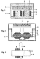
- Fig. 1 shows a highly schematic embodiment of a drive system of the invention Razor in section.
- the drive system of the razor is as Oscillating linear motor formed, the two movable engine components 1 and 2 has, which are arranged at a small distance from each other.
- the first engine component 1 consists of an iron core 3, the two in the direction of the second engine component 2 extending legs 4 has.
- On each leg 4 is a wire wound Coil 5 is arranged, wherein the coils 5 as separate individual coils or as a common coil can be operated.
- the second engine component 2 has three Permanent magnets 6 on, each with antiparallel oriented polarity side by side on a common support plate 7 are arranged, so that in each case one of the magnetic poles for Iron core 3 of the first engine component 1 points out.
- the support plate 7 is as well the iron core 3 made of a ferrous material.
- the two engine components 1 and 2 are tight arranged side by side, so that the permanent magnets 6 from the end face of the respectively adjacent Leg 4 of the iron core 3 each separated only by a small air gap 8 are.
- the width of the air gaps 8 is determined by two leaf springs 9, each are fixed laterally on the iron core 3 and on the support plate 7.
- the leaf springs 9 have the Property that they are both rigid within the plane they build up Behave body and give it to spring resiliently.
- the coils 5 each act as an electromagnet and generate supported by the iron core 3, a magnetic field on the permanent magnets. 6 acts and a relative movement between the coil 5 and the permanent magnet 6 for Episode has.
- the magnetic field generated by the coils 5 can each be reversed, so that the first and second engine components 1 and 2 in to each other in opposite phase vibrations are added.
- both the first engine component 1 and the second engine component 2 moves, d. h., That the linear motor has no stator, with whose help a runner is driven, but two mutually oscillating engine components 1 and 2, driving each other.
- One of these engine components 1 or 2 corresponds to the rotor of a conventional linear motor.
- the other takes over Functions of the stator of a conventional linear motor, but is in contrast to this not static, but also moving.
- the frequency of the oscillatory motion of the two engine components 1 and 2 is set via the control of the coil 5 and in particular adjusted so that it corresponds to the resonant frequency of the vibration system caused by the two engine components 1 and 2 and the leaf springs 9 is formed. Under resonance conditions results in a very robust vibration behavior and it is only one-comparative low energy intake required.
- Fig. 2 shows a highly schematic partial view of the razor according to the invention with the in Fig. 1 illustrated embodiment of the linear motor.
- the view is on the immediate Installation environment of the linear motor in the razor limited.
- the linear motor is suspended over the leaf springs 9 on a housing 10 of the razor, d. H. in the illustrated Embodiment take over the leaf springs 9 in addition to the movable Coupling of the two engine components 1 and 2 with each other the function of the suspension of the linear motor on the housing 10. Details of a possible geometric Design of the leaf springs 9 will be explained with reference to FIG. 3.
- a suspension of the Linear motor by means of the leaf springs 9 offers itself, because in contrast to conventional Linear motors both engine components 1 and 2 move and thus a screw with the housing 10 or other rigid attachment of one of the engine components 1 or 2 is out of the question.
- Through the leaf springs 9 can be a frictionless Suspension can be realized and also the appearance of unwanted vibrations of the housing 10 are largely avoided. So that the linear motor despite this loose suspension assumes a defined rest position and to stabilize the leaf springs 9 is at least one of the leaf springs 9 via an additional spring element 11 with the housing 10th connected.
- a shearing blade 12 is further shown, which at the first Engine component 1 or on the second engine component 2 is mounted.
- shearing blades 12 one being on the first motor component 1 and the other is attached to the second engine component 2.
- the Shearing blade 12 or each of the two shearing blades 12 is driven by the linear motor, so that it performs a reciprocating motion.
- Fig. 3 shows an embodiment of the leaf spring 9 in the installed state in side view.
- the view is chosen so that the two engine components 1 and 2, which are covered by the leaf spring 9, swing perpendicular to the plane of the drawing.
- the leaf spring 9 is cross-shaped in this embodiment and has a relatively wide horizontal bar 13 and a centrally arranged thereto, comparatively narrow vertical beam 14, which are integrally formed with each other.
- the horizontal bar 13 serves to connect the first and second motor components 1 and 2.
- the vertical bar 14 serves to suspend the linear motor on the housing 10 of the razor and, due to its geometry, has a substantially smaller spring constant than the horizontal bar 13.
- Fig. 3 differs slightly from that shown in Fig. 2
- Leaf springs 9 from, as the additional spring element 11 of FIG. 2 in the form of the lower Section of the vertical bar 14 is integrated in the leaf spring 9, d. H. the leaf springs 9 as shown in FIG. 2 do not need this lower portion and thus instead of a cross shape have a T-shape.
- the attachment to the housing 10 takes place in each case at the bottom and at the upper end of the vertical bar 14.
- the central arrangement of the vertical Beam 14 on the horizontal bar 13 and the correspondingly central suspension of the Horizontal bar 13 it is also possible to provide two vertical bars 14, which in the both end portions of the horizontal bar 13 are arranged and a terminal Suspension of the horizontal bar 13 serve on the housing 10.
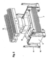
- FIG. 4 shows a perspective partial view of an embodiment of the device according to the invention Razor in a Fig. 2 corresponding section.
- FIG. 5 again shows the same illustration as Fig. 4, although some covers are removed, so that more details are visible.
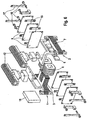
- An exploded view associated with FIG. 5 is shown in FIG. 6 displayed.
- Essential for the invention are shown in Figs. 4 to 6 training of the linear motor and its suspension in the razor. The other training, not shown of the razor can be done in a conventional manner.
- the engine components 1 and 2 correspond in shape substantially to the in Fig. 1 illustrated embodiment, wherein the second engine component 2, however has now four permanent magnets 6 instead of three permanent magnets 6.
- a shearing blade 12 is mounted, so that the two shearing blades 12 in phase opposition oscillate to each other.
- the arrangement of the blades 12 on the engine components 1 and 2 takes place crosswise, so that the first of the engine component. 1 driven razor 12 is disposed over the second motor component 2 and the shearing blades 12 driven by the second engine component 2 over the first engine component 1.
- a leveling compound 18 is attached to the rotor 7.
- each through spacers 15 are kept at a distance from each other and clamped together by means of screws 16 and are attached to the two engine components 1 and 2.
- Swinging bridges 17 are provided, which are formed as regions of tapered strip are and are usually made analogous to the leaf springs 9 of a spring steel. At one end of the swing bridges 17 are each together with the leaf springs. 9 screwed to one of the engine components 1 or 2. At the other end are the swinging bridges 17 screwed to the housing 10.
- the two Stack of leaf springs 9 continuously bent elastically so that their narrow sides in each case deflected in opposite directions, with the direction of the deflection reversed periodically.
- Ends of the swinging bridges 17 With the narrow sides of the leaf springs 9 and the attached thereto Ends of the swinging bridges 17 periodically deflected.
- the swing bridges 17 are dimensioned very weak, However, these deflections are hardly transmitted to the housing 10. However, you can the swing bridges 17 in this case, no significant angular momentum or record linear impulse.
- the geometry of the linear motor is therefore to be interpreted so that preferably no resulting angular momentum and as far as possible no resulting linear momentum occurs. This can be achieved by having the center of gravity of the first Engine component 1 including all moving components and the center of mass the second engine component 2 including all moving components move along the same straight line. Furthermore, the linear pulses should be the first and the second engine component 1 and 2 including each moving Components should be the same.
Landscapes
- Engineering & Computer Science (AREA)
- Power Engineering (AREA)
- Dry Shavers And Clippers (AREA)
- Reciprocating, Oscillating Or Vibrating Motors (AREA)
- Lock And Its Accessories (AREA)
- Transmission Devices (AREA)
- Apparatuses For Generation Of Mechanical Vibrations (AREA)
- Brushes (AREA)
Abstract
Description
Die Erfindung betrifft ein elektrisches Kleingerät mit einer Antriebseinrichtung zur Erzeugung einer oszillierenden Bewegung. Bei dem Kleingerät kann es sich insbesondere um einen elektrischen Rasierer oder eine elektrische Zahnbürste handeln.The invention relates to a small electrical appliance with a drive device for generating an oscillating movement. The small appliance can be in particular a electric razor or an electric toothbrush.
Aus der DE 1 151 307 A ist ein Schwingankerantrieb für Trockenrasiergeräte mit hin- und hergehender Arbeitsbewegung eines Schermessers bekannt. Der bekannte Schwingankerantrieb weist einen mit dem Gehäuse des Rasiergeräts fest verbundenen und U-förmig ausgebildeten Elektromagneten auf. In der Nähe der Pole des Elektromagneten sind ein Arbeitsanker und beiderseits des Arbeitsankers massensymmetrisch je ein schwingfähiger Ausgleichsanker angeordnet. Der Arbeitsanker und die Ausgleichsanker sind jeweils mittels einer U-förmigen Blattfeder beweglich aufgehängt. Im Betriebszustand schwingt der Arbeitsanker, der das Schermesser antreibt, parallel zu den Polflächen des feststehenden Elektromagneten, wobei die Ausgleichsanker eine dazu gegenphasige Schwingbewegung ausführen, um eine Übertragung der Schwingungen des Arbeitsankers auf das Gehäuse des Rasiergeräts möglichst zu verhindern.From DE 1 151 307 A is a rocker armature drive for dry shavers with back and hergehender work movement of a Schermesserers known. The well-known oscillating armature drive has a firmly connected to the housing of the shaver and U-shaped trained electromagnet on. Near the poles of the electromagnet are a Work Anchors and on both sides of the work anchor mass symmetry ever a swinging Balancing anchors arranged. The working anchor and the compensating anchors are each by means of a U-shaped leaf spring suspended movably. In operation, the work anchor swings, which drives the shearing blade, parallel to the pole faces of the fixed electromagnet, wherein the compensating anchors perform an antiphase oscillatory motion, to a transmission of the vibrations of the working anchor on the housing of the shaver possible to prevent.
Die DE 196 80 506 T1 offenbart einen elektrischen Rasierapparat mit einem oszillierenden Linearmotor, der einen stationären Elektromagneten und mehrere bewegliche Komponenten aufweist, die mit Hilfe des Elektromagneten in zueinander gegenphasige Schwingungsbewegungen versetzt werden. Der Elektromagnet ist fest mit dem Chassis des Rasierapparats verschraubt. Die beweglichen Komponenten sind über eine Blattfeder beweglich am Chassis aufgehängt. Die Blattfeder ist mehrfach geschlitzt, so daß sich die einzelnen Komponenten in zueinander entgegengesetzte Richtungen bewegen können.DE 196 80 506 T1 discloses an electric shaver with an oscillating Linear motor, which has a stationary electromagnet and several moving components having, by means of the electromagnet in mutually opposite-phase oscillatory movements be offset. The electromagnet is fixed to the chassis of the shaver screwed. The moving components are movable on the chassis via a leaf spring suspended. The leaf spring is slotted several times, so that the individual components can move in opposite directions.
Der Erfindung liegt die Aufgabe zugrunde, bei einem elektrischen Kleingerät auf möglichst optimale Weise eine oszillierende Bewegung zu erzeugen und die Entstehung unerwünschter Gerätevibrationen möglichst zu vermeiden.The invention is based on the object with a small electrical appliance as possible optimal way to create an oscillating motion and the emergence undesirable Avoid device vibration as much as possible.
Diese Aufgabe wird durch die Merkmalskombination gemäß Anspruch 1 gelöst.This object is achieved by the feature combination according to
Das erfindungsgemäße elektrisches Kleingerät verfügt über eine Antriebseinrichtung zum Erzeugen einer oszillierenden Bewegung wenigstens einer Arbeitseinheit des elektrischen Kleingeräts. Die Antriebseinrichtung weist eine erste Antriebskomponente, eine zweite Antriebskomponente und eine Spule zur Ausbildung eines Magnetfelds auf, das von der ersten Antriebskomponente ausgeht und auf die zweite Antriebskomponente, die beweglich im elektrischen Kleingerät angeordnet ist, derart einwirkt, daß die zweite Antriebskomponente in eine oszillierende Bewegung versetzt wird. Die Erfindung zeichnet sich dadurch aus, daß die erste Antriebskomponente zur Ausführung einer zur zweiten Antriebskomponente gegenphasig oszillierenden Bewegung beweglich im elektrischen Kleingerät angeordnet ist und daß die Antriebseinrichtung mittels wenigstens eines ersten Federelements am elektrischen Kleingerät befestigt ist.The small electrical appliance according to the invention has a drive device for Generating an oscillating movement of at least one working unit of the electrical Small appliance. The drive device has a first drive component, a second drive component and a coil for forming a magnetic field from the first Drive component goes out and on the second drive component, which is movable in the small electrical appliance is arranged, acts in such a way that the second drive component in an oscillating movement is added. The invention is characterized in that the first drive component for executing an antiphase to the second drive component oscillating motion is movably arranged in the small electrical appliance and that the drive device by means of at least one first spring element on the electric Small appliance is attached.
Dadurch, daß die zwei Antriebskomponenten gegenphasig zueinander schwingen wird eine wesentlich höhere Relativgeschwindigkeit zwischen den Antriebskomponenten erzielt als bei einem herkömmlichen Antrieb, bei dem sich nur eine Antriebskomponente bewegt und die andere Antriebskomponente ruht. Da der Wirkungsgrad bei derartigen Antrieben mit der Relativgeschwindigkeit der Antriebskomponenten zueinander zunimmt, lassen sich mit der erfindungsgemäßen Antriebseinrichtung höhere Wirkungsgrade erreichen als mit vergleichbaren bekannten Antrieben. Die Aufhängung mittels eines Federelements hat den Vorteil, daß sie zum einen nahezu reibungsfrei ist und zum anderen die restlichen Bestandteile des Kleingeräts, insbesondere das Gehäuse, schwingungsmäßig von der Antriebseinrichtung weitgehend abkoppelt.The fact that the two drive components oscillate in phase opposition to one another significantly higher relative speed between the drive components achieved than at a conventional drive in which moves only a drive component and the other drive component rests. Since the efficiency of such drives with the Relative speed of the drive components increases each other, can be with the Drive device according to the invention achieve higher efficiencies than comparable known drives. The suspension by means of a spring element has the advantage that on the one hand it is almost frictionless and on the other hand the remaining components of the Small device, in particular the housing, vibrationally from the drive device largely decoupled.
Die erste Antriebskomponente und die zweite Antriebskomponente können mittels wenigstens eines zweiten Federelements miteinander verbunden sein. Dies hat den Vorteil, daß eine weitgehend reibungsfreie Relativbewegung zwischen den beiden Komponenten ermöglicht wird. Gleichzeitig werden dadurch auch die für den Betrieb der Antriebseinrichtung benötigten Rückstellkräfte erzeugt. Die Federkonstante des zweiten Federelements ist vorzugsweise größer als die Federkonstante des ersten Federelements. Dadurch wird zum einen eine relativ straffe Kopplung der beiden Komponenten untereinander und zum anderen eine relativ lockere Kopplung der Antriebseinrichtung an das Gehäuse des Kleingeräts ermöglicht.The first drive component and the second drive component can by means of at least a second spring element to be interconnected. This has the advantage that allows a largely frictionless relative movement between the two components becomes. At the same time thereby also required for the operation of the drive device Restoring forces generated. The spring constant of the second spring element is preferably greater than the spring constant of the first spring element. This will be the one a relatively tight coupling of the two components with each other and on the other allows a relatively loose coupling of the drive means to the housing of the small appliance.
Im bevorzugten Ausführungsbeispiel des erfindungsgemäßen Kleingeräts ist das erste und/oder das zweite Federelement als Blattfeder ausgebildet. Eine Blattfeder ist nur bzgl. einer Raumrichtung elastisch nachgiebig ausgebildet. Bzgl. der beiden anderen Raumrichtungen verhält sie sich wie ein starrer Körper und kann somit in diesen Raumrichtungen zusätzlich statische Funktionen übernehmen. Weitere Vorteile der Blattfeder bestehen darin, daß sie extrem wenig Bauraum beansprucht und kostengünstig verfügbar ist. In the preferred embodiment of the small appliance according to the invention is the first and / or the second spring element designed as a leaf spring. A leaf spring is only regarding. a spatial direction formed elastically yielding. Concerning. the other two spatial directions behaves like a rigid body and thus can in addition to these spatial directions assume static functions. Further advantages of the leaf spring are that it requires extremely little space and is available at low cost.
Das erste und das zweite Federelement können als eine integrale Einheit ausgebildet sein. Dadurch kann die Anzahl der Einzelteile des erfindungsgemäßen Kleingeräts reduziert werden. Insbesondere können das erste Federelement und das zweite Federelement als eine gemeinsame Blattfeder in Form eines Kreuzes ausgebildet sein.The first and second spring members may be formed as an integral unit. As a result, the number of individual parts of the small appliance according to the invention can be reduced. In particular, the first spring element and the second spring element as a be formed common leaf spring in the form of a cross.
Die zweiten Federelemente können stapelförmig übereinander angeordnet sein. Dies hat den Vorteil, daß sich sehr hohe Federkonstanten und damit eine sehr starke Kopplung der beiden Antriebskomponenten realisieren lassen. Um die Reibung möglichst gering zu halten ist es dabei von Vorteil, die zweiten Federelemente durch Zwischenstücke auf Abstand zueinander gehalten werden.The second spring elements can be stacked one above the other. this has the advantage that very high spring constants and thus a very strong coupling of can be realized both drive components. To keep the friction as low as possible It is advantageous, the second spring elements by spacers at a distance from each other being held.
Zur Festlegung einer Ruheposition der Antriebseinrichtung kann ein drittes Federelement vorgesehen sein.To establish a rest position of the drive device, a third spring element be provided.
In einem bevorzugten Ausführungsbeispiel bewegen sich die Massenschwerpunkte der ersten Antriebskomponente und der zweiten Antriebskomponente inklusive sich mit der ersten Antriebskomponente oder der zweiten Antriebskomponente mitbewegender Bauteile auf einer gemeinsamen Geraden. Dadurch wird verhindert, daß ein resultierender Drehimpuls erzeugt wird. Weiterhin wird die Antriebseinrichtung vorzugsweise so ausgebildet, daß die linearen Impulse der ersten Antriebskomponente und der zweiten Antriebskomponente inklusive sich mit der ersten Antriebskomponente oder der zweiten Antriebskomponente mitbewegender Bauteile entgegengesetzt gleich sind, so daß kein resultierender linearer Impuls erzeugt wird. Durch diese Maßnahmen ist es möglich, das zweite Federelement sehr schwach zu dimensionieren und damit eine nahezu vollständige Entkopplung der Antriebseinrichtung vom Gehäuse des Kleingeräts zu erreichen.In a preferred embodiment, the centers of gravity of the first move Drive component and the second drive component included with the first Drive component or the second drive component with moving components a common line. This prevents that a resulting angular momentum is produced. Furthermore, the drive device is preferably formed so that the including linear pulses of the first drive component and the second drive component moving with the first drive component or the second drive component Components are equal opposite, so that no resulting linear pulse is produced. By these measures it is possible, the second spring element very to dimension weak and thus an almost complete decoupling of the drive device to reach from the housing of the small appliance.
Wenigstens eine der beiden Antriebskomponenten kann einen oder mehrere Dauermagnete aufweisen. Weiterhin kann wenigstens eine der beiden Antriebskomponenten einen Wickelkern aufweisen, auf dem die Spule angeordnet ist. Damit läßt sich bei relativ geringen Abmessungen ein leistungsstarker Antrieb realisieren, dessen Stromaufnahme ausreichend gering ist, um beispielsweise einen Akku-Betrieb des elektrischen Kleingeräts zuzulassen.At least one of the two drive components may have one or more permanent magnets exhibit. Furthermore, at least one of the two drive components can have a winding core have, on which the coil is arranged. This can be at relatively small dimensions realize a powerful drive whose power consumption is sufficient is low, for example, to allow battery operation of the small electrical appliance.
Die Erfindung wird nachstehend an Hand der in der Zeichnung dargestellten Ausführungsbeispiele erläutert. Die Ausführungsbeispiele beziehen sich jeweils auf einen elektrischen Rasierer. Die Erfindung eignet sich aber auch für andere elektrische Kleingeräte wie beispielsweise eine elektrische Zahnbürste.The invention will be described below with reference to the embodiments illustrated in the drawings explained. The embodiments each relate to an electrical Razor. The invention is also suitable for other small electrical appliances such as an electric toothbrush.
Es zeigen
- Fig. 1
- ein stark schematisiertes Ausführungsbeispiel eines Antriebssystems des erfindungsgemäßen Rasierers in Schnittdarstellung,
- Fig. 2
- eine stark schematisierte Teilansicht des erfindungsgemäßen Rasierers mit dem in Fig. 1 dargestellten Ausführungsbeispiel des Linearmotors,
- Fig. 3
- ein Ausführungsbeispiel für eine Blattfeder im eingebauten Zustand in Seitenansicht,
- Fig. 4
- eine perspektivische Teilansicht eines Ausführungsbeispiels des erfindungsgemäßen Rasierers, wobei ein Fig. 2 entsprechender Ausschnitt dargestellt ist,
- Fig. 5
- eine Fig. 4 entsprechende Darstellung, wobei allerdings einige Abdeckungen entfernt sind, so daß mehr Einzelheiten sichtbar sind und
- Fig. 6
- das Ausführungsbeispiel aus Fig. 5 in einer perspektivischen Explosionsdarstellung.
- Fig. 1
- a highly schematic embodiment of a drive system of the razor according to the invention in a sectional view,
- Fig. 2
- a highly schematic partial view of the razor according to the invention with the embodiment of the linear motor shown in Figure 1,
- Fig. 3
- an embodiment of a leaf spring in the installed state in side view,
- Fig. 4
- 1 is a partial perspective view of an embodiment of the razor according to the invention, wherein a corresponding Fig. 2 cutout is shown,
- Fig. 5
- a representation corresponding to Fig. 4, but with some covers are removed, so that more details are visible and
- Fig. 6
- the embodiment of FIG. 5 in a perspective exploded view.
Fig. 1 zeigt ein stark schematisiertes Ausführungsbeispiel eines Antriebssystems des erfindungsgemäßen
Rasierers in Schnittdarstellung. Das Antriebssystem des Rasierers ist als
oszillierender Linearmotor ausgebildet, der zwei bewegliche Motorkomponenten 1 und 2
aufweist, die in einem geringen Abstand zueinander angeordnet sind. Die erste Motorkomponente
1 besteht aus einem Eisenkern 3, der zwei sich in Richtung der zweiten Motorkomponente
2 erstreckende Schenkel 4 aufweist. Auf jedem Schenkel 4 ist eine aus Draht gewickelte
Spule 5 angeordnet, wobei die Spulen 5 als separate Einzelspulen oder als eine
gemeinsame Spule betrieben werden können. Die zweite Motorkomponente 2 weist drei
Dauermagnete 6 auf, die jeweils mit antiparallel orientierter Polung nebeneinander auf einer
gemeinsamen Trägerplatte 7 angeordnet sind, so daß jeweils einer der Magnetpole zum
Eisenkern 3 der ersten Motorkomponente 1 hin weist. Die Trägerplatte 7 besteht ebenso wie
der Eisenkern 3 aus einem Eisenwerkstoff. Die beiden Motorkomponenten 1 und 2 sind dicht
nebeneinander angeordnet, so daß die Dauermagnete 6 von der Stirnseite des jeweils benachbarten
Schenkels 4 des Eisenkerns 3 jeweils nur durch einen kleinen Luftspalt 8 getrennt
sind. Die Breite der Luftspalte 8 wird durch zwei Blattfedern 9 vorgegeben, die jeweils
seitlich am Eisenkern 3 und an der Trägerplatte 7 befestigt sind. Die Blattfedern 9 haben die
Eigenschaft, daß sie sich jeweils innerhalb der von ihnen aufgespannten Ebene wie starre
Körper verhalten und senkrecht dazu federnd nachgeben. Für das in Fig. 1 dargestellte
Ausführungsbeispiel bedeutet dies, daß sich die beiden Motorkomponenten 1 und 2 unter
Überwindung der von den Blattfedern 9 erzeugten Rückstellkraft relativ zueinander nach
links und rechts bewegen können, ihr Abstand zueinander und damit auch die Breite der
Luftspalte 8 dabei aber nahezu unverändert bleiben. Damit ergibt sich ein schwingungsfähiges
System, bei dem die erste Motorkomponente 1 und die zweite Motorkomponente 2 jeweils
eine lineare Schwingungsbewegung ausführen. Die Bewegungsrichtungen der beiden
Motorkomponenten 1 und 2 sind jeweils einander entgegengesetzt, d h. die Schwingungen
verlaufen gegenphasig zueinander.Fig. 1 shows a highly schematic embodiment of a drive system of the invention
Razor in section. The drive system of the razor is as
Oscillating linear motor formed, the two
Um die Schwingungsbewegung in Gang zu bringen und aufrecht zu erhalten, wird ein
Stromfluß durch die Spulen 5 hergestellt. Die Spulen 5 wirken jeweils als Elektromagnet und
erzeugen unterstützt durch den Eisenkern 3 ein Magnetfeld, das auf die Dauermagnete 6
einwirkt und eine Relativbewegung zwischen den Spulen 5 und den Dauermagneten 6 zur
Folge hat. Durch entsprechende Ansteuerung kann das mit den Spulen 5 erzeugte Magnetfeld
jeweils umgepolt werden, so daß die erste und die zweite Motorkomponente 1 und 2 in
zueinander gegenphasige Schwingungen versetzt werden. Dabei besteht ein wesentlicher
Aspekt der Erfindung darin, daß sich sowohl die erste Motorkomponente 1 als auch die
zweite Motorkomponente 2 bewegt, d. h., daß der Linearmotor keinen Stator aufweist, mit
dessen Hilfe ein Läufer angetrieben wird, sondern zwei gegeneinander schwingende Motorkomponenten
1 und 2, die sich gegenseitig antreiben. Eine dieser Motorkomponenten 1 oder
2 entspricht dem Läufer eines herkömmlichen Linearmotors. Die andere übernimmt die
Funktionen des Stators eines herkömmlichen Linearmotors, ist aber im Gegensatz zu diesem
nicht statisch, sondern bewegt sich ebenfalls. Dies führt unter anderem auch dazu, daß
sich unter sonst gleichen Bedingungen die erste und zweite Motorkomponente 1 und 2 des
erfindungsgemäßen Linearmotors mit einer Relativgeschwindigkeit zueinander bewegen, die
doppelt so hoch wie die Relativgeschwindigkeit zwischen einem Stator und einem Läufer
eines herkömmlichen Linearmotors ist. Dadurch läßt sich ein relativ hoher Wirkungsgrad
erzielen. Die Frequenz der Schwingungsbewegung der beiden Motorkomponenten 1 und 2
wird über die Ansteuerung der Spulen 5 vorgegeben und insbesondere so eingestellt, daß
sie der Resonanzfrequenz des Schwingungssystems entspricht, das durch die beiden Motorkomponenten
1 und 2 und die Blattfedern 9 gebildet wird. Unter Resonanzbedingungen
ergibt sich ein sehr robustes Schwingungsverhalten und es ist lediglich eine-vergleichsweise
geringe Energiezufuhr erforderlich.To get the vibrational motion going and maintain it, one becomes
Current flow through the
Fig. 2 zeigt eine stark schematisierte Teilansicht des erfindungsgemäßen Rasierers mit dem
in Fig. 1 dargestellten Ausführungsbeispiel des Linearmotors. Die Ansicht ist auf die unmittelbare
Einbauumgebung des Linearmotors im Rasierer beschränkt. Der Linearmotor ist
über die Blattfedern 9 an einem Gehäuse 10 des Rasierers aufgehängt, d. h. in dem dargestellten
Ausführungsbeispiel übernehmen die Blattfedern 9 zusätzlich zur beweglichen
Kopplung der beiden Motorkomponenten 1 und 2 untereinander die Funktion der Aufhängung
des Linearmotors am Gehäuse 10. Einzelheiten zu einer möglichen geometrischen
Ausgestaltung der Blattfedern 9 werden an Hand von Fig. 3 erläutert. Ein Aufhängung des
Linearmotors mittels der Blattfedern 9 bietet sich deshalb an, weil sich im Gegensatz zu herkömmlichen
Linearmotoren beide Motorkomponenten 1 und 2 bewegen und somit eine Verschraubung
mit dem Gehäuse 10 oder eine andere starre Befestigung einer der Motorkomponenten
1 oder 2 nicht in Frage kommt. Durch die Blattfedern 9 kann eine reibungsfreie
Aufhängung realisiert werden und zudem das Auftreton unerwünschter Vibrationen des Gehäuses
10 weitgehend vermieden werden. Damit der Linearmotor trotz dieser losen Aufhängung
eine definierte Ruheposition einnimmt und zur Stabilisierung der Blattfedern 9 ist wenigstens
eine der Blattfedern 9 über ein zusätzliches Federelement 11 mit dem Gehäuse 10
verbunden. In der Fig. 2 ist weiterhin ein Schermesser 12 dargestellt, das an der ersten
Motorkomponente 1 oder an der zweiten Motorkomponente 2 angebracht ist. Alternativ dazu
können auch zwei Schermesser 12 vorgesehen sein wobei das eine an der ersten Motorkomponente
1 und das andere an der zweiten Motorkomponente 2 angebracht ist. Das
Schermesser 12 bzw. jedes der beiden Schermesser 12 wird von dem Linearmotor angetrieben,
so daß es eine hin- und hergehende Bewegung ausführt.Fig. 2 shows a highly schematic partial view of the razor according to the invention with the
in Fig. 1 illustrated embodiment of the linear motor. The view is on the immediate
Installation environment of the linear motor in the razor limited. The linear motor is
suspended over the
Fig. 3 zeigt ein Ausführungsbeispiel für die Blattfeder 9 im eingebauten Zustand in Seitenansicht.
Die Ansicht ist dabei so gewählt, daß die beiden Motorkomponenten 1 und 2, die durch
die Blattfeder 9 verdeckt sind, senkrecht zur Zeichenebene schwingen. Die Blattfeder 9 ist
bei diesem Ausführungsbeispiel kreuzförmig ausgebildet und weist einen relativ breiten horizontalen
Balken 13 und einen mittig dazu angeordneten, vergleichsweise schmalen vertikalen
Balken 14 auf, die einteilig miteinander ausgebildet sind. Der horizontale Balken 13 dient
der Verbindung der ersten und zweiten Motorkomponente 1 und 2. Der vertikale Balken 14
dient der Aufhängung des Linearmotors am Gehäuse 10 des Rasierers und weist infolge
seiner Geometrie eine wesentlich kleinere Federkonstante als der horizontale Balken 13 auf. Fig. 3 shows an embodiment of the
Das Ausführungsbeispiel der Fig. 3 weicht insofern geringfügig von den in Fig. 2 dargestellten
Blattfedern 9 ab, als das zusätzliche Federelement 11 gemäß Fig. 2 in Form des unteren
Abschnitts des vertikalen Balkens 14 in die Blattfeder 9 integriert ist, d. h. die Blattfedern 9
gemäß Fig. 2 benötigen diesen unteren Abschnitt nicht und können somit statt einer Kreuzform
eine T-Form aufweisen. Die Befestigung am Gehäuse 10 erfolgt jeweils am unteren
und am oberen Ende des vertikalen Balkens 14. Statt der mittigen Anordnung des vertikalen
Balkens 14 am horizontalen Balken 13 und der dementsprechend mittigen Aufhängung des
horizontalen Balkens 13 ist es auch möglich, zwei vertikale Balken 14 vorzusehen, die in den
beiden Endbereichen des horizontalen Balkens 13 angeordnet sind und einer endständigen
Aufhängung des horizontalen Balkens 13 am Gehäuse 10 dienen. Bei dieser Variante weist
die Blattfeder 9 statt der Kreuzform eine H-Form auf. Bei der Befestigung der Blattfeder 9
am Gehäuse 10 ist dann allerdings zu berücksichtigen, daß die Schwingungsbewegungen
der beiden Motorkomponenten 1 und 2 auf die vertikalen Balken 14 der Blattfeder übertragen
werden.The embodiment of Fig. 3 differs slightly from that shown in Fig. 2
Leaf springs 9 from, as the
Figur 4 zeigt eine perspektivische Teilansicht eines Ausführungsbeispiels des efindungsgemäßen Rasierers in einem Fig. 2 entsprechenden Ausschnitt. Figur 5 zeigt nochmals die gleiche Darstellung wie Fig. 4, wobei allerdings einige Abdeckungen entfernt sind, so daß mehr Einzelheiten sichtbar sind. Eine zu Fig. 5 zugehörige Explosionsdarstellung ist in Fig. 6 abgebildet. Wesentlich für die Erfindung sind die in den Fig. 4 bis 6 dargestellte Ausbildung des Linearmotors und dessen Aufhängung im Rasierer. Die nicht dargestellte sonstige Ausbildung des Rasierers kann auf herkömmliche Weise erfolgen.FIG. 4 shows a perspective partial view of an embodiment of the device according to the invention Razor in a Fig. 2 corresponding section. FIG. 5 again shows the same illustration as Fig. 4, although some covers are removed, so that more details are visible. An exploded view associated with FIG. 5 is shown in FIG. 6 displayed. Essential for the invention are shown in Figs. 4 to 6 training of the linear motor and its suspension in the razor. The other training, not shown of the razor can be done in a conventional manner.
Die Motorkomponenten 1 und 2 entsprechen in ihrer Formgebung im Wesentlichen dem in
Fig. 1 dargestellten Ausführungsbeispiel, wobei die zweite Motorkomponente 2 allerdings
statt drei Dauermagneten 6 nunmehr vier Dauermagnete 6 aufweist. Auf jeder Motorkomponente
1 und 2 ist ein Schermesser 12 montiert, so daß sich die beiden Schermesser 12 gegenphasig
zueinander oszillieren. Die Anordnung der Schermesser 12 auf den Motorkomponenten
1 und 2 erfolgt dabei über Kreuz, so daß das von der ersten Motorkomponente 1
angetriebene Schermesser 12 über der zweiten Motorkomponente 2 angeordnet ist und das
von der zweiten Motorkomponente 2 angetriebene Schermesser 12 über der ersten Motorkomponente
1. Zusätzlich ist am Läufer 7 eine Ausgleichsmasse 18 angebracht. Dadurch
soll erreicht werden, daß sich die Massenschwerpunkte der ersten Motorkomponente 1 und
der zweiten Motorkomponente 2 inklusive der sich mitbewegenden Bauteile wie beispielsweise
die Schermesser 12 möglichst auf einer gemeinsamen Geraden bewegen, so daß
kein oder nur ein geringer resultierender Drehimpuls auftritt, der störende Vibrationen zur
Folge hat. Statt je einer einzelnen Blattfeder 9 ist beiderseits des Linearmotors jeweils ein
Stapel von drei rechteckig ausgebildeten Blattfedern 9 angeordnet, die jeweils durch Zwischenstücke
15 auf Abstand zueinander gehalten werden und mittels Schrauben 16 zusammengespannt
und an den beiden Motorkomponenten 1 und 2 befestigt sind. Durch die
Zwischenstücke 15 soll die Reibung zwischen den einzelnen Blattfedern 9 eines Stapels
reduziert werden. Für die Aufhängung des Linearmotors am Gehäuse 10 sind vier separate
Schwingbrücken 17 vorgesehen, die als sich bereichsweise verjüngende Streifen ausgebildet
sind und in der Regel analog zu den Blattfedern 9 aus einem Federstahl gefertigt sind.
An ihrem einen Ende sind die Schwingbrücken 17 jeweils gemeinsam mit den Blattfedern 9
an eine der Motorkomponenten 1 oder 2 angeschraubt. An dem jeweils anderen Ende sind
die Schwingbrücken 17 mit dem Gehäuse 10 verschraubt.The
Im Betriebszustand führen die beiden Motorkomponenten 1 und 2 und mit ihnen die Schermesser
12 eine zueinander gegenphasige lineare Schwingung aus. Dabei werden die beiden
Stapel von Blattfedern 9 fortwährend elastisch gebogen, so daß ihre Schmalseiten jeweils in
entgegengesetzter Richtung ausgelenkt werden, wobei sich die Richtung der Auslenkung
periodisch umkehrt. Mit den Schmalseiten der Blattfedern 9 werden auch die daran befestigten
Enden der Schwingbrücken 17 periodisch ausgelenkt. Wenn die Schwingbrücken 17,
wie das im vorliegenden Ausführungsbeispiel der Fall ist, sehr schwach dimensioniert sind,
werden diese Auslenkungen jedoch kaum auf das Gehäuse 10 übertragen. Allerdings können
die Schwingbrücken 17 in diesem Fall auch keinen nennenswerten Drehimpuls oder
linearen Impuls aufnehmen. Die Geometrie des Linearmotors ist daher so auszulegen, daß
möglichst kein resultierender Drehimpuls und möglichst kein resultierender linearer Impuls
auftritt. Dies kann dadurch erreicht werden daß sich der Massenschwerpunkt der ersten
Motorkomponente 1 einschließlich aller sich mitbewegender Bauteile und der Massenschwerpunkt
der zweiten Motorkomponente 2 einschließlich aller sich mitbewegender Bauteile
entlang der gleichen Geraden bewegen. Weiterhin sollten die linearen Impulse der ersten
und der zweiten Motorkomponente 1 und 2 einschließlich der sich jeweils mitbewegenden
Bauteile entgegengesetzt gleich sein.In operation, the two
Claims (13)
- A small electric appliance with a drive mechanism for generating an oscillatory motion of at least one working unit (12) of the small electric appliance, said drive mechanism having a first drive component (1), a second drive component (2), and a coil (5) for producing a magnetic field that extends from the first drive component (1) and acts on the second drive component (2) that is movably arranged in the small electric appliance, in such a way that the second drive component (2) is set in an oscillatory motion, characterized in that the first drive component (1) is movably arranged in the small electric appliance in order to execute an oscillatory motion in phase opposition to the second drive component (2), while the air gap between associated drive components is maintained essentially constant, and that the drive mechanism is fastened to the small electric appliance by means of at least one first spring element (14, 17).
- The small electric appliance as claimed in claim 1, characterized in that the first drive components (1) and the second drive component (2) are interconnected by means of at least one second spring element (9, 13).
- The small electric appliance as claimed in claim 2, characterized in that the spring constant of the second spring element (9, 13) is greater than the spring constant of the first spring element (14, 17).
- The small electric appliance as claimed in any one of the preceding claims, characterized in that the first spring element (14, 17) and/or the second spring element (9, 13) is/are constructed as a leaf spring.
- The small electric appliance as claimed in any one of the claims 2 to 4, characterized in that the first spring element (14) and the second spring element (13) are constructed as an integral unit.
- The small electric appliance as claimed in claim 5, characterized in that the first spring element (14) and the second spring element (13) are constructed as a common leaf spring in the form of a cross.
- The small electric appliance as claimed in any one of the claims 2 to 4, characterized in that several second spring elements (9) are arranged in stack form one above the other.
- The small electric appliance as claimed in claim 7, characterized in that spacers (15) are provided to maintain the second spring elements (9) in spaced relation to each other.
- The small electric appliance as claimed in any one of the preceding claims, characterized in that provision is made for a third spring element (11) to define a position of rest for the drive mechanism.
- The small electric appliance as claimed in any one of the preceding claims, characterized in that the mass centers of gravity of the first drive component (1) and of the second drive component (2), including parts co-moving with the first drive component (1) or the second drive component (2), move on a common straight line.
- The small electric appliance as claimed in any one of the preceding claims, characterized in that the momentums of the first drive component(1) and of the second drive component (2), including parts co-moving with the first drive component (1) or the second drive component (2), are opposite and equal.
- The small electric appliance as claimed in any one of the preceding claims, characterized in that at least one of the two drive components (1, 2) has at least one permanent magnet (6).
- The small electric appliance as claimed in any one of the preceding claims, characterized in that at least one of the two drive components (1, 2) has a core (3) around which the coil (5) is wound.
Applications Claiming Priority (3)
| Application Number | Priority Date | Filing Date | Title |
|---|---|---|---|
| DE10242091A DE10242091A1 (en) | 2002-09-11 | 2002-09-11 | Small electrical device with a drive device for generating an oscillating movement |
| DE10242091 | 2002-09-11 | ||
| PCT/EP2003/009152 WO2004028759A1 (en) | 2002-09-11 | 2003-08-19 | Small electrical appliance with a drive device for generation of an oscillating movement |
Publications (2)
| Publication Number | Publication Date |
|---|---|
| EP1539439A1 EP1539439A1 (en) | 2005-06-15 |
| EP1539439B1 true EP1539439B1 (en) | 2005-12-21 |
Family
ID=31969067
Family Applications (1)
| Application Number | Title | Priority Date | Filing Date |
|---|---|---|---|
| EP03798107A Expired - Lifetime EP1539439B1 (en) | 2002-09-11 | 2003-08-19 | Small electrical appliance with a drive device for generation of an oscillating movement |
Country Status (7)
| Country | Link |
|---|---|
| EP (1) | EP1539439B1 (en) |
| JP (1) | JP4679902B2 (en) |
| CN (1) | CN100346945C (en) |
| AT (1) | ATE313419T1 (en) |
| AU (1) | AU2003258629A1 (en) |
| DE (2) | DE10242091A1 (en) |
| WO (1) | WO2004028759A1 (en) |
Families Citing this family (12)
| Publication number | Priority date | Publication date | Assignee | Title |
|---|---|---|---|---|
| DE102005044176A1 (en) | 2005-09-16 | 2007-03-29 | Braun Gmbh | Hair removal device |
| DE102005044175A1 (en) * | 2005-09-16 | 2007-03-29 | Braun Gmbh | Hair removal device |
| DE102005060653A1 (en) * | 2005-12-19 | 2007-06-21 | Robert Bosch Gmbh | Device for detecting an object |
| DE102006034050A1 (en) * | 2006-07-20 | 2008-01-24 | Braun Gmbh | Electric shaver |
| FR2971902B1 (en) * | 2011-02-23 | 2013-11-08 | Moving Magnet Tech | ELECTROMAGNETIC ACTUATOR WITH IMPROVED FORCE DENSITY AND APPLICATION TO AN ELECTRIC RAZOR |
| JP6275501B2 (en) * | 2014-02-07 | 2018-02-07 | マクセルホールディングス株式会社 | Electric razor |
| US10792138B2 (en) | 2015-01-28 | 2020-10-06 | Shanghai Shift Electrics Co., Ltd. | Cleaning device |
| CN106324959B (en) | 2015-07-01 | 2018-08-21 | 中强光电股份有限公司 | Vibrate lens module and projection arrangement |
| JP6793366B2 (en) * | 2017-04-19 | 2020-12-02 | パナソニックIpマネジメント株式会社 | Vibration type linear actuator and cutting device |
| JP6765079B2 (en) * | 2017-04-19 | 2020-10-07 | パナソニックIpマネジメント株式会社 | Vibration type linear actuator and hair treatment machine |
| CN108258874B (en) * | 2017-12-27 | 2019-11-01 | 广州赤力科技有限公司 | Rotary actuator and electric device |
| CN112803697B (en) * | 2021-01-18 | 2022-03-25 | 深圳市泓之发机电有限公司 | Linear drive assembly |
Family Cites Families (8)
| Publication number | Priority date | Publication date | Assignee | Title |
|---|---|---|---|---|
| CH265598A (en) * | 1946-01-23 | 1949-12-15 | Odstrcil Borivoj | Dry shaver. |
| NL264048A (en) * | 1960-09-29 | |||
| GB1028215A (en) * | 1963-02-02 | 1966-05-04 | Morphy Richards Cray Ltd | Improvements relating to vibrator motors for electric dry shavers and other electro-mechanical devices |
| FR2212673B2 (en) * | 1972-12-29 | 1977-02-25 | Crouzet Sa | |
| JP3266757B2 (en) * | 1995-05-26 | 2002-03-18 | 松下電工株式会社 | Vibration type linear actuator |
| DE19736776C2 (en) * | 1997-08-23 | 1999-06-02 | Braun Gmbh | Dry shaver |
| EP1162721B1 (en) * | 2000-06-07 | 2005-12-21 | Matsushita Electric Works, Ltd. | Linear oscillating actuator |
| US6873067B2 (en) * | 2000-09-29 | 2005-03-29 | Matsushita Electric Works, Ltd. | Linear oscillator |
-
2002
- 2002-09-11 DE DE10242091A patent/DE10242091A1/en not_active Withdrawn
-
2003
- 2003-08-19 EP EP03798107A patent/EP1539439B1/en not_active Expired - Lifetime
- 2003-08-19 DE DE50302024T patent/DE50302024D1/en not_active Expired - Lifetime
- 2003-08-19 CN CNB038216744A patent/CN100346945C/en not_active Expired - Lifetime
- 2003-08-19 WO PCT/EP2003/009152 patent/WO2004028759A1/en active IP Right Grant
- 2003-08-19 AT AT03798107T patent/ATE313419T1/en active
- 2003-08-19 AU AU2003258629A patent/AU2003258629A1/en not_active Abandoned
- 2003-08-19 JP JP2004538809A patent/JP4679902B2/en not_active Expired - Lifetime
Also Published As
| Publication number | Publication date |
|---|---|
| DE50302024D1 (en) | 2006-01-26 |
| JP2005537898A (en) | 2005-12-15 |
| DE10242091A1 (en) | 2004-04-01 |
| WO2004028759A1 (en) | 2004-04-08 |
| AU2003258629A1 (en) | 2004-04-19 |
| JP4679902B2 (en) | 2011-05-11 |
| CN1681628A (en) | 2005-10-12 |
| CN100346945C (en) | 2007-11-07 |
| EP1539439A1 (en) | 2005-06-15 |
| ATE313419T1 (en) | 2006-01-15 |
Similar Documents
| Publication | Publication Date | Title |
|---|---|---|
| EP1539437B1 (en) | Small electrical appliance with a drive device for generation of an oscillating movement | |
| EP1509368B1 (en) | Drive device for generating an oscillating motion for a small electric appliance | |
| EP1641602B1 (en) | Small electrical appliance comprising an electric motor for generating an oscillating displacement | |
| EP2108215B1 (en) | Drive device for driving a brush element of an electric toothbrush | |
| EP1687887B1 (en) | Electric motor for an electrical small-scale unit | |
| EP1102517B1 (en) | Electroacoustic transducer for hearing aids | |
| EP1539439B1 (en) | Small electrical appliance with a drive device for generation of an oscillating movement | |
| DE10001162A1 (en) | Electromagnetic vibrator for controlling linear vibrator, has pair of solenoids fastened together with connecting piece directed outwards, and legs directed towards one another | |
| EP1108283A1 (en) | Electromagnetic actuator with an oscillating spring-mass system | |
| DE102006034050A1 (en) | Electric shaver | |
| DE69819014T2 (en) | ELECTROMAGNETIC DRIVE WITH TWO COUNTER-PHASE MOBILE PARTS | |
| DE102008051126A1 (en) | Electromagnetic exciter and manufacturing method therefor | |
| DE102005060537A1 (en) | Electric shaver with oscillating shaving head | |
| DE10242094B4 (en) | Drive device for generating an oscillating movement for a small electrical appliance | |
| DE69920116T2 (en) | Electromagnetic motor and active vibration device using such a motor | |
| EP1539438B1 (en) | Drive device for the generation of an oscillating movement for a small electrical appliance | |
| DE60317738T2 (en) | An oscillating linear actuator | |
| DE60034627T2 (en) | Resonance device such as bat or power generator | |
| EP1642380B1 (en) | Method for controlling an electric motor comprising several oscillating motor components | |
| DE2336759A1 (en) | Electric razor oscillating armature AC motor - has helical springs with non-linear adjustable characteristics each side of armature | |
| DE1203510B (en) | Electromagnetic vibration exciter | |
| DE3409182A1 (en) | Magnetic drive system | |
| DE4117226A1 (en) | Electrically-operated vibration device for razor or hair-cutter - has lever device between oscillation element operated via stator and vibration stage | |
| DE8407692U1 (en) | MAGNETIC DRIVE DEVICE |
Legal Events
| Date | Code | Title | Description |
|---|---|---|---|
| PUAI | Public reference made under article 153(3) epc to a published international application that has entered the european phase |
Free format text: ORIGINAL CODE: 0009012 |
|
| 17P | Request for examination filed |
Effective date: 20050211 |
|
| AK | Designated contracting states |
Kind code of ref document: A1 Designated state(s): AT BE BG CH CY CZ DE DK EE ES FI FR GB GR HU IE IT LI LU MC NL PT RO SE SI SK TR |
|
| AX | Request for extension of the european patent |
Extension state: AL LT LV MK |
|
| GRAP | Despatch of communication of intention to grant a patent |
Free format text: ORIGINAL CODE: EPIDOSNIGR1 |
|
| GRAS | Grant fee paid |
Free format text: ORIGINAL CODE: EPIDOSNIGR3 |
|
| GRAA | (expected) grant |
Free format text: ORIGINAL CODE: 0009210 |
|
| AK | Designated contracting states |
Kind code of ref document: B1 Designated state(s): AT BE BG CH CY CZ DE DK EE ES FI FR GB GR HU IE IT LI LU MC NL PT RO SE SI SK TR |
|
| DAX | Request for extension of the european patent (deleted) | ||
| PG25 | Lapsed in a contracting state [announced via postgrant information from national office to epo] |
Ref country code: IT Free format text: LAPSE BECAUSE OF FAILURE TO SUBMIT A TRANSLATION OF THE DESCRIPTION OR TO PAY THE FEE WITHIN THE PRESCRIBED TIME-LIMIT;WARNING: LAPSES OF ITALIAN PATENTS WITH EFFECTIVE DATE BEFORE 2007 MAY HAVE OCCURRED AT ANY TIME BEFORE 2007. THE CORRECT EFFECTIVE DATE MAY BE DIFFERENT FROM THE ONE RECORDED. Effective date: 20051221 Ref country code: FI Free format text: LAPSE BECAUSE OF FAILURE TO SUBMIT A TRANSLATION OF THE DESCRIPTION OR TO PAY THE FEE WITHIN THE PRESCRIBED TIME-LIMIT Effective date: 20051221 Ref country code: RO Free format text: LAPSE BECAUSE OF FAILURE TO SUBMIT A TRANSLATION OF THE DESCRIPTION OR TO PAY THE FEE WITHIN THE PRESCRIBED TIME-LIMIT Effective date: 20051221 Ref country code: SI Free format text: LAPSE BECAUSE OF FAILURE TO SUBMIT A TRANSLATION OF THE DESCRIPTION OR TO PAY THE FEE WITHIN THE PRESCRIBED TIME-LIMIT Effective date: 20051221 Ref country code: SK Free format text: LAPSE BECAUSE OF FAILURE TO SUBMIT A TRANSLATION OF THE DESCRIPTION OR TO PAY THE FEE WITHIN THE PRESCRIBED TIME-LIMIT Effective date: 20051221 Ref country code: IE Free format text: LAPSE BECAUSE OF FAILURE TO SUBMIT A TRANSLATION OF THE DESCRIPTION OR TO PAY THE FEE WITHIN THE PRESCRIBED TIME-LIMIT Effective date: 20051221 Ref country code: CZ Free format text: LAPSE BECAUSE OF FAILURE TO SUBMIT A TRANSLATION OF THE DESCRIPTION OR TO PAY THE FEE WITHIN THE PRESCRIBED TIME-LIMIT Effective date: 20051221 Ref country code: NL Free format text: LAPSE BECAUSE OF FAILURE TO SUBMIT A TRANSLATION OF THE DESCRIPTION OR TO PAY THE FEE WITHIN THE PRESCRIBED TIME-LIMIT Effective date: 20051221 |
|
| REG | Reference to a national code |
Ref country code: GB Ref legal event code: FG4D Free format text: NOT ENGLISH |
|
| REG | Reference to a national code |
Ref country code: CH Ref legal event code: EP |
|
| GBT | Gb: translation of ep patent filed (gb section 77(6)(a)/1977) |
Effective date: 20051221 |
|
| REG | Reference to a national code |
Ref country code: IE Ref legal event code: FG4D Free format text: LANGUAGE OF EP DOCUMENT: GERMAN |
|
| REF | Corresponds to: |
Ref document number: 50302024 Country of ref document: DE Date of ref document: 20060126 Kind code of ref document: P |
|
| PG25 | Lapsed in a contracting state [announced via postgrant information from national office to epo] |
Ref country code: SE Free format text: LAPSE BECAUSE OF FAILURE TO SUBMIT A TRANSLATION OF THE DESCRIPTION OR TO PAY THE FEE WITHIN THE PRESCRIBED TIME-LIMIT Effective date: 20060321 Ref country code: BG Free format text: LAPSE BECAUSE OF FAILURE TO SUBMIT A TRANSLATION OF THE DESCRIPTION OR TO PAY THE FEE WITHIN THE PRESCRIBED TIME-LIMIT Effective date: 20060321 Ref country code: DK Free format text: LAPSE BECAUSE OF FAILURE TO SUBMIT A TRANSLATION OF THE DESCRIPTION OR TO PAY THE FEE WITHIN THE PRESCRIBED TIME-LIMIT Effective date: 20060321 Ref country code: GR Free format text: LAPSE BECAUSE OF FAILURE TO SUBMIT A TRANSLATION OF THE DESCRIPTION OR TO PAY THE FEE WITHIN THE PRESCRIBED TIME-LIMIT Effective date: 20060321 |
|
| PG25 | Lapsed in a contracting state [announced via postgrant information from national office to epo] |
Ref country code: ES Free format text: LAPSE BECAUSE OF FAILURE TO SUBMIT A TRANSLATION OF THE DESCRIPTION OR TO PAY THE FEE WITHIN THE PRESCRIBED TIME-LIMIT Effective date: 20060401 |
|
| PG25 | Lapsed in a contracting state [announced via postgrant information from national office to epo] |
Ref country code: PT Free format text: LAPSE BECAUSE OF FAILURE TO SUBMIT A TRANSLATION OF THE DESCRIPTION OR TO PAY THE FEE WITHIN THE PRESCRIBED TIME-LIMIT Effective date: 20060522 |
|
| NLV1 | Nl: lapsed or annulled due to failure to fulfill the requirements of art. 29p and 29m of the patents act | ||
| PG25 | Lapsed in a contracting state [announced via postgrant information from national office to epo] |
Ref country code: HU Free format text: LAPSE BECAUSE OF FAILURE TO SUBMIT A TRANSLATION OF THE DESCRIPTION OR TO PAY THE FEE WITHIN THE PRESCRIBED TIME-LIMIT Effective date: 20060622 |
|
| REG | Reference to a national code |
Ref country code: IE Ref legal event code: FD4D |
|
| ET | Fr: translation filed | ||
| PG25 | Lapsed in a contracting state [announced via postgrant information from national office to epo] |
Ref country code: MC Free format text: LAPSE BECAUSE OF NON-PAYMENT OF DUE FEES Effective date: 20060831 |
|
| PLBE | No opposition filed within time limit |
Free format text: ORIGINAL CODE: 0009261 |
|
| STAA | Information on the status of an ep patent application or granted ep patent |
Free format text: STATUS: NO OPPOSITION FILED WITHIN TIME LIMIT |
|
| 26N | No opposition filed |
Effective date: 20060922 |
|
| REG | Reference to a national code |
Ref country code: CH Ref legal event code: PL |
|
| PG25 | Lapsed in a contracting state [announced via postgrant information from national office to epo] |
Ref country code: CH Free format text: LAPSE BECAUSE OF NON-PAYMENT OF DUE FEES Effective date: 20070831 Ref country code: LI Free format text: LAPSE BECAUSE OF NON-PAYMENT OF DUE FEES Effective date: 20070831 |
|
| PG25 | Lapsed in a contracting state [announced via postgrant information from national office to epo] |
Ref country code: EE Free format text: LAPSE BECAUSE OF FAILURE TO SUBMIT A TRANSLATION OF THE DESCRIPTION OR TO PAY THE FEE WITHIN THE PRESCRIBED TIME-LIMIT Effective date: 20051221 |
|
| PG25 | Lapsed in a contracting state [announced via postgrant information from national office to epo] |
Ref country code: LU Free format text: LAPSE BECAUSE OF NON-PAYMENT OF DUE FEES Effective date: 20060819 Ref country code: TR Free format text: LAPSE BECAUSE OF FAILURE TO SUBMIT A TRANSLATION OF THE DESCRIPTION OR TO PAY THE FEE WITHIN THE PRESCRIBED TIME-LIMIT Effective date: 20051221 |
|
| PG25 | Lapsed in a contracting state [announced via postgrant information from national office to epo] |
Ref country code: CY Free format text: LAPSE BECAUSE OF FAILURE TO SUBMIT A TRANSLATION OF THE DESCRIPTION OR TO PAY THE FEE WITHIN THE PRESCRIBED TIME-LIMIT Effective date: 20051221 |
|
| REG | Reference to a national code |
Ref country code: FR Ref legal event code: PLFP Year of fee payment: 14 |
|
| REG | Reference to a national code |
Ref country code: FR Ref legal event code: PLFP Year of fee payment: 15 |
|
| REG | Reference to a national code |
Ref country code: FR Ref legal event code: PLFP Year of fee payment: 16 |
|
| PGFP | Annual fee paid to national office [announced via postgrant information from national office to epo] |
Ref country code: SK Payment date: 20180806 Year of fee payment: 16 Ref country code: AT Payment date: 20180725 Year of fee payment: 16 |
|
| REG | Reference to a national code |
Ref country code: AT Ref legal event code: MM01 Ref document number: 313419 Country of ref document: AT Kind code of ref document: T Effective date: 20190819 |
|
| PG25 | Lapsed in a contracting state [announced via postgrant information from national office to epo] |
Ref country code: AT Free format text: LAPSE BECAUSE OF NON-PAYMENT OF DUE FEES Effective date: 20190819 |
|
| REG | Reference to a national code |
Ref country code: BE Ref legal event code: MM Effective date: 20190831 |
|
| PG25 | Lapsed in a contracting state [announced via postgrant information from national office to epo] |
Ref country code: BE Free format text: LAPSE BECAUSE OF NON-PAYMENT OF DUE FEES Effective date: 20190831 |
|
| PGFP | Annual fee paid to national office [announced via postgrant information from national office to epo] |
Ref country code: GB Payment date: 20220630 Year of fee payment: 20 |
|
| PGFP | Annual fee paid to national office [announced via postgrant information from national office to epo] |
Ref country code: DE Payment date: 20220705 Year of fee payment: 20 |
|
| PGFP | Annual fee paid to national office [announced via postgrant information from national office to epo] |
Ref country code: FR Payment date: 20220709 Year of fee payment: 20 |
|
| P01 | Opt-out of the competence of the unified patent court (upc) registered |
Effective date: 20230430 |
|
| REG | Reference to a national code |
Ref country code: DE Ref legal event code: R071 Ref document number: 50302024 Country of ref document: DE |
|
| REG | Reference to a national code |
Ref country code: GB Ref legal event code: PE20 Expiry date: 20230818 |
|
| PG25 | Lapsed in a contracting state [announced via postgrant information from national office to epo] |
Ref country code: GB Free format text: LAPSE BECAUSE OF EXPIRATION OF PROTECTION Effective date: 20230818 |