EP1539438B1 - Drive device for the generation of an oscillating movement for a small electrical appliance - Google Patents
Drive device for the generation of an oscillating movement for a small electrical appliance Download PDFInfo
- Publication number
- EP1539438B1 EP1539438B1 EP03798106A EP03798106A EP1539438B1 EP 1539438 B1 EP1539438 B1 EP 1539438B1 EP 03798106 A EP03798106 A EP 03798106A EP 03798106 A EP03798106 A EP 03798106A EP 1539438 B1 EP1539438 B1 EP 1539438B1
- Authority
- EP
- European Patent Office
- Prior art keywords
- drive
- drive mechanism
- spring element
- components
- component
- Prior art date
- Legal status (The legal status is an assumption and is not a legal conclusion. Google has not performed a legal analysis and makes no representation as to the accuracy of the status listed.)
- Expired - Lifetime
Links
Images

Classifications
-
- B—PERFORMING OPERATIONS; TRANSPORTING
- B26—HAND CUTTING TOOLS; CUTTING; SEVERING
- B26B—HAND-HELD CUTTING TOOLS NOT OTHERWISE PROVIDED FOR
- B26B19/00—Clippers or shavers operating with a plurality of cutting edges, e.g. hair clippers, dry shavers
- B26B19/28—Drive layout for hair clippers or dry shavers, e.g. providing for electromotive drive
- B26B19/288—Balance by opposing oscillation
-
- B—PERFORMING OPERATIONS; TRANSPORTING
- B26—HAND CUTTING TOOLS; CUTTING; SEVERING
- B26B—HAND-HELD CUTTING TOOLS NOT OTHERWISE PROVIDED FOR
- B26B19/00—Clippers or shavers operating with a plurality of cutting edges, e.g. hair clippers, dry shavers
- B26B19/28—Drive layout for hair clippers or dry shavers, e.g. providing for electromotive drive
- B26B19/282—Motors without a rotating central drive shaft, e.g. linear motors
-
- H—ELECTRICITY
- H02—GENERATION; CONVERSION OR DISTRIBUTION OF ELECTRIC POWER
- H02K—DYNAMO-ELECTRIC MACHINES
- H02K33/00—Motors with reciprocating, oscillating or vibrating magnet, armature or coil system
- H02K33/16—Motors with reciprocating, oscillating or vibrating magnet, armature or coil system with polarised armatures moving in alternate directions by reversal or energisation of a single coil system
-
- H—ELECTRICITY
- H02—GENERATION; CONVERSION OR DISTRIBUTION OF ELECTRIC POWER
- H02K—DYNAMO-ELECTRIC MACHINES
- H02K33/00—Motors with reciprocating, oscillating or vibrating magnet, armature or coil system
- H02K33/18—Motors with reciprocating, oscillating or vibrating magnet, armature or coil system with coil systems moving upon intermittent or reversed energisation thereof by interaction with a fixed field system, e.g. permanent magnets
Definitions
- the invention relates to a drive device for generating an oscillating movement of at least one working unit of a small electrical appliance according to the preamble of claim 1. Furthermore, the invention relates to a small electrical appliance that has such a drive unit.
- the small appliance may in particular be an electric razor or an electric toothbrush.
- a vibrating anchor drive for dry shaving with reciprocating working movement of a shear knife is known.
- the known oscillating armature drive has a permanently connected to the housing of the shaver and U-shaped electromagnet.
- a working anchor and on both sides of the working anchor mass symmetry each arranged a swinging compensating anchor.
- the working anchor and the compensating anchors are each suspended movably by means of a U-shaped leaf spring.
- the working anchor which drives the shearing blade, oscillates parallel to the pole faces of the fixed electromagnet, with the counterpoise anchors in antiphase swinging motion to prevent transmission of the working armature vibrations to the shaver housing as much as possible.
- DE 196 80 506 T1 discloses an electric shaver with an oscillating linear motor having a stationary electromagnet and a plurality of movable components, which are offset by means of the electromagnet in mutually opposite-phase oscillatory movements.
- the electromagnet is firmly bolted to the chassis of the shaver.
- the moving components are suspended on the chassis via a leaf spring.
- the leaf spring is slotted multiple times, so that the movable components can move in opposite directions. To maintain the antiphase between the movable components, these are connected to each other via a link which is rotatably mounted on a fixed axis.
- an electric shaver with a linear drive which has a hollow cylindrical stator with an electromagnetic coil.
- the stator two movable elements are arranged, which are driven in phase opposition to each other and one of which drives a cutter and the other for suppression unwanted vibrations may have a counterweight.
- the two movable elements are connected to a spring element which is attached to the stator.
- the invention has for its object to provide a drive device for a small electrical appliance, can be generated with the most optimal way oscillating movements and unwanted device vibrations are avoided as possible.
- the first drive component is arranged for performing a movement to the second drive component in opposite phase oscillating movement in the small electrical appliance.
- the drive device furthermore has a coupling element, by means of which a rigid coupling and in a direction perpendicular thereto an elastic coupling between the two drive components is formed in a direction parallel to the direction of movement of the two drive components.
- the fact that the two drive components oscillate in phase opposition to one another results in a significantly higher relative speed between the drive components than in a conventional drive in which only one drive component moves and the other drive component rests. Since the efficiency increases in such drives with the relative speed of the drive components to each other, higher efficiencies can be achieved with the drive device according to the invention than with comparable known drives.
- the inventive design of the coupling element has the advantage that on the one hand an exact compliance with the antiphase and a predeterminable ratio of the vibration amplitudes of the two drive components is ensured. On the other hand, by the elastic coupling transversely to the direction of movement of the two drive components also simplifies the articulation of the coupling element to the drive components, since no clearance is required.
- a game-affixed attachment has a number of disadvantages, is in the context of the invention of the possibility for play-free attachment of the coupling element to the two drive components usually made use of. This has the advantage that the attachment cost and can be made compact and subject to wear. Another advantage is that in contrast to a game attachment does not cause noise.
- the coupling element has a rigid element and a first spring element.
- the first spring element can be attached to the rigid element and to one of the two drive components.
- the coupling element usually has a second spring element which is fastened to the rigid element and to the other drive component.
- the coupling element may still have a third spring element which is fixed to the rigid element and to a frame.
- the first spring element and / or the second spring element and / or the third spring element may be designed to be rigid in a direction parallel to the direction of movement of the two drive components and elastically in a direction perpendicular thereto.
- the rigid element preferably has two individual components, which are arranged side by side, wherein between the individual components, the third spring element is fixed and at the two free ends of the individual components, the first spring element and the second spring element are attached.
- the individual components are in particular U-shaped.
- the coupling element may be pivotally suspended in order to carry out the movement direction reversal required for the opposite-phase movement of the two drive components.
- the pivot axis is oriented in particular perpendicular to the direction of movement of the two drive components. If a movement of the two drive components with the same oscillation amplitude is desired, the pivot axis can be arranged centrally between the attachment of the coupling element to the first drive component and the attachment of the coupling element to the second drive component. It is advantageous if the suspension of the coupling element is formed without play, as this can achieve a high precision and no wear or noise problems occur.
- a fourth spring element can be attached to the frame and to the coupling element.
- the fourth spring element is preferably elastic in a direction parallel to the direction of movement of the two drive components and rigid in a direction perpendicular thereto and serves together with the third spring element of the pivotable suspension of the coupling element on the frame.
- Each pivoting movement of the coupling element is thus accompanied only with a slight elastic yielding of the third and fourth spring element, so that a bearing point with mutually rotatable parts can be avoided. This results in the already mentioned advantages in wear and noise and continue to be insensitive to moisture.
- the two drive components can be connected to one another via at least one fifth spring element, which is designed to be elastic in a direction parallel to the direction of movement of the two drive components.
- This has the advantage that a largely friction-free relative movement between the two drive components is made possible.
- a plurality of fifth spring elements can be stacked one above the other, so that can be realized in this way very high spring constants, which also can be very easily vary over the number of spring elements used. Accordingly, it is also easy to set the resonance frequency of the drive device to a desired value.
- the drive device For attachment to the electrical appliance, the drive device preferably has at least one sixth spring element, which is designed to be elastic in one direction parallel to the direction of movement of the two drive components.
- a frictionless suspension of the drive device in the electrical device can be realized, which also has the advantage that it largely decouples the electrical device vibrationally from the drive device.
- the first spring element, the second spring element, the third spring element, the fourth spring element, the fifth spring element and / or the sixth spring element may each be formed as a leaf spring.
- a leaf spring is elastically yielding only with respect to a spatial direction. Concerning. In the two other spatial directions, it behaves like a rigid body and can therefore assume additional static functions in these spatial directions. Further advantages of the leaf spring are that it requires extremely little space and is available at low cost.
- At least one of the two drive components may comprise one or more permanent magnets. Furthermore, at least one of the two drive components can have a winding core on which the coil is arranged. This can be at relatively small dimensions realize a powerful drive whose power consumption is sufficiently low, for example, to allow battery operation of the small electrical appliance
- the drive device is preferably designed such that in the operating state the centers of gravity of the first drive component including moving components and the second drive component including moving components move on a common line, in particular a straight line. It is particularly advantageous if this line or straight line lies in the common plane of movement of the two drive components (x-z plane according to FIG. 1).
- the pivot axis of the coupling element crosses this line or straight line.
- the drive device can be designed so that in the operating state, the linear pulses of the first drive component including moving components and the second drive component including moving components are the same opposite.
- the frame can be firmly connected to the small appliance, so that all components mounted on the frame can be supported on the small appliance.
- the small appliance according to the invention preferably has a self-learning electronics for controlling the drive unit under resonance conditions.
- the invention will be explained below with reference to the embodiment shown in the drawing, which relates to a drive device for an electric shaver.
- the invention is also suitable for other small electrical appliances such as an electric toothbrush.
- Fig. 1 shows an embodiment of the drive device according to the invention in a perspective view.
- the drive device according to the invention is designed as an oscillating linear motor having two movable motor components 1 and 2.
- the two engine components 1 and 2 are arranged at a small distance from each other.
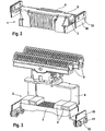
- the engine components 1 and 2 are each shown again separately, namely the first engine component 1 in Fig. 2 and the second engine component 2 in Fig. 3.
- the type of representation corresponds in each case to FIG. 1.
- the first motor component 1 shown in FIG. 2 consists of an iron core 3 and a wire wound coil 4, which is arranged on the iron core 3.
- a first holding frame 5 is attached, which serves to attach other components.
- the second motor component 2 shown in FIG. 3 has four permanent magnets 6, which are each arranged in pairs on a common carrier plate 7. In this case, two permanent magnets 6 are mounted side by side with antiparallel oriented polarity on the support plate 7.
- the support plate 7 is rod-shaped and, like the iron core 3 made of a ferrous material or other ferromagnetic material.
- a second holding frame 8 is mounted, which is analogous to the first holding frame 5 of the first motor component 1 of the attachment of other components.
- each side of the two engine components 1 and 2 on the first support frame 5 and the second support frame 8 two Resonanzfedem 10 are screwed by means of screws 11 and retaining plate 12.
- the resonant springs 10 are formed as packages of a plurality of stacked leaf springs, which are each formed as a thin, rectangular plates. These plates behave like rigid bodies within the plane defined by them and yield elastically perpendicular to this plane.
- the first motor component 1 and the second motor component 2 are kept at a defined distance from each other, which is chosen so that a small air gap remains between the permanent magnet 6 and the iron core 3. Since the Resonanzfedem 10 perpendicular to their major surfaces have a spring action, the two engine components 1 and 2, despite the fixation by the resonant springs 10 in this direction over a certain mobility, so that through the two engine components 1 and 2 and the Resonance 10 a vibratory system is trained. In other words, the first engine component 1 and the second engine component 2 can each perform a linear oscillatory motion when they are deflected out of their rest position by the application of a force overcoming the restoring forces of the resonant springs 10.
- a current flow through the coil 4 is produced.
- the coil 4 acts as an electromagnet and generated by the iron core 3 generates a magnetic field which acts on the permanent magnets 6 and has a relative movement between the coil 4 and the permanent magnet 6 result.
- the x-axis of FIG. 1 thus represents the horizontal and the z-axis is the vertical.
- an essential aspect of the invention is that both the first motor component 1 and the second motor component 2 moves, ie, that the linear motor according to the invention has no stator, with the aid of a rotor is driven, but two mutually oscillating engine components 1 and 2 that drive each other.
- One of these engine components 1 or 2 corresponds to the rotor of a conventional linear motor. The other takes over the functions of the stator of a conventional linear motor, but in contrast to this is not static, but also moves.
- this also means that, under otherwise identical conditions, the first and second motor components 1 and 2 of the linear motor according to the invention move relative to one another at a relative speed which is twice the relative speed between a stator and a rotor of a conventional linear motor. As a result, a relatively high efficiency can be achieved in the linear motor according to the invention.
- the frequency of the vibration movements of the two engine components 1 and 2 is determined by the control of the coil 4 and in particular adjusted so that it corresponds to the resonant frequency of the vibration system, which is formed by the two engine components 1 and 2 and the resonance springs 10.
- This can be done by means of a self-learning electronics, with which the coil 4 is driven, wherein the oscillation amplitude can be controlled by a pulse width modulation. Under resonant conditions results in a very robust vibration behavior and it is only a comparatively low energy input required.
- the linear motor according to the invention is structurally designed so that as possible no vibrations are transmitted to the razor. To achieve this, it is necessary that both the resulting from the movement of the engine components 1 and 2 angular momentum and the resulting linear pulse is as possible to zero.
- the resulting angular momentum is zero when the center of gravity of the first engine component 1 including moving components and the center of gravity of the second engine component 2, including moving components, move along a common straight line. This is achieved in the embodiment shown in FIGS. 1 to 3, characterized in that the first engine component 1 is very compact and is enclosed by the slightly larger second engine component 2, wherein the mass distributions of the second engine component 2 on opposite sides of the first engine component. 1 are coordinated with each other.
- the shearing blades 9 are taken into account.
- the linear momentum of the first motor component 1 including moving components and the linear momentum of the second motor component 2, including moving components must be the same. This is fulfilled at the same oscillation amplitude and frequency when the masses are equal in each case taking into account the components moving together.
- the first and second engine components 1 and 2 not only the distribution of the masses but also the numerical values for the total masses are to be matched.
- a retaining spring 13 is attached to the first holding frame 5 and to the second holding frame 8 by the screws 11 and the holding platelets 12.
- the retaining springs 13 are also formed as leaf springs and have the form of thin plates, which are partially slotted on two opposite sides, so that each retaining spring 13 has two strips 14 which are connected by narrow webs 15 with the remaining spring body.
- Each strip 14 has a hole at its loose end 16, which serves to attach to the razor.
- a coupling element 17 which mechanically couples the two engine components 1 and 2 together.
- This coupling is beyond the coupling caused by the Resonanzfedem 10 insofar as it is absolutely rigid parallel to the direction of movement of the two engine components 1 and 2 and thus their movements precisely and permanently synchronized with each other.
- the synchronization is fully maintained even if the two engine components 1 and 2 are exposed to different loads and is designed so that the two engine components 1 and 2 swing exactly opposite to each other in phase.
- the coupling element 17 causes in a direction perpendicular to the direction of movement of the engine components 1 and 2 no rigid, but an elastic coupling.
- the coupling element 17 has two U-shaped struts 18 which are arranged perpendicular to the direction of movement of the two engine components 1 and 2 side by side, that the outer sides of each leg 19 of the two struts 18 are adjacent to each other.
- a first spring element 20 and a second spring element 21 are fixed, which are each formed as a strip-shaped leaf spring and extending in a direction parallel to the direction of movement of the two engine components 1 and 2.
- the first spring element 20 is screwed with its free end and the first holding frame 5.
- the second spring element 21 is screwed with its free end on the second holding frame 8.
- a third spring element 22 is attached, wherein the attachment, as well as the first spring element 20 and the second spring element 21, preferably by welding. Also, the third spring element 22 is formed as a strip-shaped leaf spring and oriented parallel to the first spring element 20 and the second spring element 21. With its free end, the third spring element 22 is screwed to a frame 23 having a bore 24 for attachment to the razor.
- a fourth spring element 25 is screwed, which is formed according to the first, second and third spring element 20, 21 and 22, but in contrast to this with its longitudinal extent in a direction perpendicular to the direction of movement of the two engine components 1 and 2 is oriented ,
- the other end of the fourth spring element 25 is in the vicinity the adjacent leg 19 attached to one of the struts 18.
- the attachment takes place via a screw connection to a holder 26, which is welded to one of the struts 18.
- the coupling element 17 behaves in a direction parallel to the direction of movement of the two engine components 1 and 2 rigid and elastic in a direction perpendicular thereto.
- the already mentioned precise freezing of the phase relationship between the two engine components 1 and 2 is possible.
- the struts 18 alternately perform tilting movements to the right and to the left during operation of the linear motor, so that their extension in the vertical direction changes continuously.
- a pivot axis must be defined as accurately as possible for the tilting movement of the coupling element 17.
- the struts 18 are fixed at one point by the third spring element 22 parallel to the direction of movement of the engine components 1 and 2 and by the fourth spring element 25 perpendicular thereto.
- the so fixed point forms the pivot axis for the tilting movement of the coupling element 17 and is arranged in accordance with FIG. 1 centrally in the longitudinal extent of the existing of the two struts 18 structure.
- a central arrangement of the pivot axis has the consequence that the two engine components 1 and 2 oscillate with the same amplitude.
- an eccentric arrangement of the pivot axis is instead selected.
- the embodiment shown in Fig. 1 has, as a further peculiarity that the pivot axis crosses the straight line on which move the centers of gravity of the two engine components 1 and 2, including the thus driven shearing blades 9. As a result, virtually no unwanted vibration is transmitted to the razor.
- Fig. 1 The embodiment shown in Fig. 1 is further characterized in that all connections are performed without play, with the interconnected items are rigidly attached to each other at the place of connection.
- An optionally required freedom of movement between the connected individual parts is achieved in each case by the use of leaf springs or of leaf spring arrangements, with which even a pivotable articulation can be realized in the manner described above. This procedure results in a high precision, a very low friction, a very low wear and a very low-noise operation of the linear motor according to the invention.
- the carrier parts used in the linear motor according to the invention such as the first holding frame 5, the second holding frame 8, the holding plate 12, the struts 18, the frame 23 and the holder 26 can be inexpensively made of stamped and bent sheet metal parts.
- the individual parts or assemblies which have to assume a precisely defined position and / or orientation relative to each other, are precisely aligned with each other and fixed in this aligned state for each individual copy.
Abstract
Description
Die Erfindung betrifft eine Antriebseinrichtung zum Erzeugen einer oszillierenden Bewegung wenigstens einer Arbeitseinheit eines elektrischen Kleingeräts gemäß dem Oberbegriff des Anspruchs 1. Weiterhin betrifft die Erfindung ein elektrisches Kleingerät, das über eine derartige Antriebseinheit verfügt. Bei dem Kleingerät kann es sich insbesondere um einen elektrischen Rasierer oder eine elektrische Zahnbürste handeln.The invention relates to a drive device for generating an oscillating movement of at least one working unit of a small electrical appliance according to the preamble of
Aus der DE 1 151 307 A ist ein Schwingankerantrieb für Trockenrasiergeräte mit hin- und hergehender Arbeitsbewegung eines Schermessers bekannt. Der bekannte Schwingankerantrieb weist einen mit dem Gehäuse des Rasiergeräts fest verbundenen und U-förmig ausgebildeten Elektromagneten auf. In der Nähe der Pole des Elektromagneten sind ein Arbeitsanker und beiderseits des Arbeitsankers massensymmetrisch je ein schwingfähiger Ausgleichsanker angeordnet. Der Arbeitsanker und die Ausgleichsanker sind jeweils mittels einer U-förmigen Blattfeder beweglich aufgehängt. Im Betriebszustand schwingt der Arbeitsanker, der das Schermesser antreibt, parallel zu den Polflächen des feststehenden Elektromagneten, wobei die Ausgleichsanker eine dazu gegenphasige Schwingbewegung ausführen, um eine Übertragung der Schwingungen des Arbeitsankers auf das Gehäuse des Rasiergeräts möglichst zu verhindern.From DE 1 151 307 A a vibrating anchor drive for dry shaving with reciprocating working movement of a shear knife is known. The known oscillating armature drive has a permanently connected to the housing of the shaver and U-shaped electromagnet. In the vicinity of the poles of the electromagnet are a working anchor and on both sides of the working anchor mass symmetry each arranged a swinging compensating anchor. The working anchor and the compensating anchors are each suspended movably by means of a U-shaped leaf spring. In operation, the working anchor, which drives the shearing blade, oscillates parallel to the pole faces of the fixed electromagnet, with the counterpoise anchors in antiphase swinging motion to prevent transmission of the working armature vibrations to the shaver housing as much as possible.
Die DE 196 80 506 T1 offenbart einen elektrischen Rasierapparat mit einem oszillierenden Linearmotor, der einen stationären Elektromagneten und mehrere bewegliche Komponenten aufweist, die mit Hilfe des Elektromagneten in zueinander gegenphasige Schwingungsbewegungen versetzt werden. Der Elektromagnet ist fest mit dem Chassis des Rasierapparats verschraubt. Die beweglichen Komponenten sind über eine Blattfeder beweglich am Chassis aufgehängt. Die Blattfeder ist mehrfach geschlitzt, so daß sich die beweglichen Komponenten in zueinander entgegengesetzte Richtungen bewegen können. Zur Erhaltung der Gegenphasigkeit zwischen den beweglichen Komponenten sind diese über einen Lenker miteinander verbunden, der drehbar an einer festen Achse gelagert ist.DE 196 80 506 T1 discloses an electric shaver with an oscillating linear motor having a stationary electromagnet and a plurality of movable components, which are offset by means of the electromagnet in mutually opposite-phase oscillatory movements. The electromagnet is firmly bolted to the chassis of the shaver. The moving components are suspended on the chassis via a leaf spring. The leaf spring is slotted multiple times, so that the movable components can move in opposite directions. To maintain the antiphase between the movable components, these are connected to each other via a link which is rotatably mounted on a fixed axis.
Aus der DE 197 81 664 C2 ist ein elektrischer Rasierer mit einem Linearantrieb bekannt, der einen hohlzylindrisch ausgebildeten Stator mit einer elektromagnetischen Spule aufweist. Im Stator sind zwei bewegliche Elemente angeordnet, die gegenphasig zueinander angetrieben werden und von denen eines ein Schermesser antreibt und das andere zur Unterdrückung unerwünschter Vibrationen ein Gegengewicht aufweisen kann. Die beiden beweglichen Elemente sind mit einem Federelement verbunden, das am Stator befestigt ist.From DE 197 81 664 C2 an electric shaver with a linear drive is known which has a hollow cylindrical stator with an electromagnetic coil. In the stator, two movable elements are arranged, which are driven in phase opposition to each other and one of which drives a cutter and the other for suppression unwanted vibrations may have a counterweight. The two movable elements are connected to a spring element which is attached to the stator.
Der Erfindung liegt die Aufgabe zugrunde, eine Antriebseinrichtung für ein elektrisches Kleingerät anzugeben, mit der sich auf möglichst optimale Weise oszillierende Bewegungen erzeugen lassen und unerwünschte Gerätevibrationen möglichst vermieden werden.The invention has for its object to provide a drive device for a small electrical appliance, can be generated with the most optimal way oscillating movements and unwanted device vibrations are avoided as possible.
Diese Aufgabe wird durch die Merkmalskombination des Anspruchs 1 gelöst.This object is achieved by the combination of features of
Die erfindungsgemäße Antriebseinrichtung zum Erzeugen einer oszillierenden Bewegung wenigstens einer Arbeitseinheit eines elektrischen Kleingeräts weist eine Spule zur Ausbildung eines Magnetfelds auf, das von einer ersten Antriebskomponente ausgeht und auf eine zweite Antriebskomponente, die beweglich im elektrischen Kleingerät angeordnet ist, derart einwirkt, daß die zweite Antriebskomponente in eine oszillierende Bewegung versetzt wird. Die erste Antriebskomponente ist zur Ausführung einer zur zweiten Antriebskomponente gegenphasig oszillierenden Bewegung beweglich im elektrischen Kleingerät angeordnet. Die Antriebseinrichtung weist weiterhin ein Koppelelement auf, durch das in einer Richtung parallel zur Bewegungsrichtung der beiden Antriebskomponenten eine starre Kopplung und in einer dazu senkrechten Richtung eine elastische Kopplung zwischen den beiden Antriebskomponenten ausgebildet wird.The drive device according to the invention for generating an oscillating movement of at least one working unit of a small electrical appliance has a coil for forming a magnetic field, which starts from a first drive component and acts on a second drive component, which is movably arranged in the small electrical appliance, such that the second drive component is placed in an oscillating motion. The first drive component is arranged for performing a movement to the second drive component in opposite phase oscillating movement in the small electrical appliance. The drive device furthermore has a coupling element, by means of which a rigid coupling and in a direction perpendicular thereto an elastic coupling between the two drive components is formed in a direction parallel to the direction of movement of the two drive components.
Dadurch, daß die zwei Antriebskomponenten gegenphasig zueinander schwingen wird eine wesentlich höhere Relativgeschwindigkeit zwischen den Antriebskomponenten erzielt als bei einem herkömmlichen Antrieb, bei dem sich nur eine Antriebskomponente bewegt und die andere Antriebskomponente ruht. Da der Wirkungsgrad bei derartigen Antrieben mit der Relativgeschwindigkeit der Antriebskomponenten zueinander zunimmt, lassen sich mit der erfindungsgemäßen Antriebseinrichtung höhere Wirkungsgrade erreichen als mit vergleichbaren bekannten Antrieben. Die erfindungsgemäße Ausbildung des Koppelelements hat den Vorteil, daß zum einen eine exakte Einhaltung der Gegenphasigkeit und eines vorgebbaren Verhältnisses der Schwingungsamplituden der beiden Antriebskomponenten sichergestellt wird. Zum anderen wird durch die elastische Kopplung quer zur Bewegungsrichtung der beiden Antriebskomponenten zudem die Anlenkung des Koppelelements an den Antriebskomponenten vereinfacht, da keinerlei Spiel erforderlich ist. Da eine spielbehaftete Befestigung eine Reihe von Nachteilen aufweist, wird im Rahmen der Erfindung von der Möglichkeit zur spielfreien Befestigung des Koppelelements an den beiden Antriebskomponenten in der Regel tatsächlich Gebrauch gemacht. Dies hat den Vorteil, daß die Befestigung kostengünstig und kompakt ausgeführt werden kann und keinem Verschleiß unterliegt. Als weiterer Vorteil kommt noch hinzu, daß es im Gegensatz zu einer Befestigung mit Spiel nicht zu einer Geräuschentwicklung kommt.The fact that the two drive components oscillate in phase opposition to one another results in a significantly higher relative speed between the drive components than in a conventional drive in which only one drive component moves and the other drive component rests. Since the efficiency increases in such drives with the relative speed of the drive components to each other, higher efficiencies can be achieved with the drive device according to the invention than with comparable known drives. The inventive design of the coupling element has the advantage that on the one hand an exact compliance with the antiphase and a predeterminable ratio of the vibration amplitudes of the two drive components is ensured. On the other hand, by the elastic coupling transversely to the direction of movement of the two drive components also simplifies the articulation of the coupling element to the drive components, since no clearance is required. Since a game-affixed attachment has a number of disadvantages, is in the context of the invention of the possibility for play-free attachment of the coupling element to the two drive components usually made use of. This has the advantage that the attachment cost and can be made compact and subject to wear. Another advantage is that in contrast to a game attachment does not cause noise.
In einem bevorzugten Ausführungsbeispiel weist das Koppelelement ein starres Element und ein erstes Federelement auf. Das erste Federelement kann dabei am starren Element und an einer der beiden Antriebskomponenten befestigt sein. Weiterhin weist das Koppelelement in der Regel ein zweites Federelement auf, das am starren Element und an der anderen Antriebskomponente befestigt ist. Schließlich kann das Koppelelement noch ein drittes Federelement aufweisen, das am starren Element und an einem Gestell befestigt ist. Das erste Federelement und/oder das zweite Federelement und/oder das dritte Federelement können in einer Richtung parallel zur Bewegungsrichtung der beiden Antriebskomponenten starr und in einer dazu senkrechten Richtung elastisch ausgebildet sein. Das starre Element weist bevorzugt zwei Einzelbauteile auf, die nebeneinander angeordnet sind, wobei zwischen den Einzelbauteilen das dritte Federelement befestigt ist und an den beiden freien Enden der Einzelbauteile das erste Federelement und das zweite Federelement befestigt sind. Dabei sind die Einzelbauteile insbesondere U-förmig ausgebildet. Auf die vorstehend beschriebene Art läßt sich das Koppelelement sehr einfach und kostengünstig realisieren. Zudem ist die Befestigung des Koppelelements an den beiden Antriebskomponenten problemlos realisierbar, da hierbei keine engen Toleranzen eingehalten werden müssen und es sich jeweils um eine starre Verbindung handelt.In a preferred embodiment, the coupling element has a rigid element and a first spring element. The first spring element can be attached to the rigid element and to one of the two drive components. Furthermore, the coupling element usually has a second spring element which is fastened to the rigid element and to the other drive component. Finally, the coupling element may still have a third spring element which is fixed to the rigid element and to a frame. The first spring element and / or the second spring element and / or the third spring element may be designed to be rigid in a direction parallel to the direction of movement of the two drive components and elastically in a direction perpendicular thereto. The rigid element preferably has two individual components, which are arranged side by side, wherein between the individual components, the third spring element is fixed and at the two free ends of the individual components, the first spring element and the second spring element are attached. The individual components are in particular U-shaped. In the manner described above, the coupling element can be realized very easily and inexpensively. In addition, the attachment of the coupling element on the two drive components can be realized easily, since this no tight tolerances must be met and it is in each case a rigid connection.
Das Koppelelement kann schwenkbar aufgehängt sein, um die für die gegenphasige Bewegung der beiden Antriebskomponenten erforderliche Bewegungsrichtungsumkehr zu vollziehen. Die Schwenkachse ist dabei insbesondere senkrecht zur Bewegungsrichtung der beiden Antriebskomponenten orientiert. Wenn eine Bewegung der beiden Antriebskomponenten mit gleicher Schwingungsamplitude gewünscht ist, kann die Schwenkachse mittig zwischen der Befestigung des Koppelelements an der ersten Antriebskomponente und der Befestigung des Koppelelements an der zweiten Antriebskomponente angeordnet sein. Dabei ist es von Vorteil, wenn die Aufhängung des Koppelelements spielfrei ausgebildet ist, da sich dadurch eine hohe Präzision erzielen läßt und keine Verschleiß- oder Geräuschprobleme auftreten. Hierzu kann an dem Gestell und am Koppelelement ein viertes Federelement befestigt sein. Das vierte Federelement ist bevorzugt in einer Richtung parallel zur Bewegungsrichtung der beiden Antriebskomponenten elastisch und in einer dazu senkrechten Richtung starr ausgebildet und dient zusammen mit dem dritten Federelement der schwenkbaren Aufhängung des Koppelelements am Gestell. Jede Schwenkbewegung des Koppelelements geht somit lediglich mit einem geringfügigen elastischen Nachgeben des dritten und vierten Federelements einher, so daß eine Lagerstelle mit zueinander drehbeweglichen Teilen vermieden werden kann. Dadurch ergeben sich die bereits angesprochenen Vorteile beim Verschleiß und bei der Geräuschentwicklung und weiterhin eine Unempfindlichkeit gegen Feuchtigkeit.The coupling element may be pivotally suspended in order to carry out the movement direction reversal required for the opposite-phase movement of the two drive components. The pivot axis is oriented in particular perpendicular to the direction of movement of the two drive components. If a movement of the two drive components with the same oscillation amplitude is desired, the pivot axis can be arranged centrally between the attachment of the coupling element to the first drive component and the attachment of the coupling element to the second drive component. It is advantageous if the suspension of the coupling element is formed without play, as this can achieve a high precision and no wear or noise problems occur. For this purpose, a fourth spring element can be attached to the frame and to the coupling element. The fourth spring element is preferably elastic in a direction parallel to the direction of movement of the two drive components and rigid in a direction perpendicular thereto and serves together with the third spring element of the pivotable suspension of the coupling element on the frame. Each pivoting movement of the coupling element is thus accompanied only with a slight elastic yielding of the third and fourth spring element, so that a bearing point with mutually rotatable parts can be avoided. This results in the already mentioned advantages in wear and noise and continue to be insensitive to moisture.
Die beiden Antriebskomponenten können über wenigstens ein fünftes Federelement, das in einer Richtung parallel zur Bewegungsrichtung der beiden Antriebskomponenten elastisch ausgebildet ist, miteinander verbunden sein. Dies hat den Vorteil, daß eine weitgehend reibungsfreie Relativbewegung zwischen den beiden Antriebskomponenten ermöglicht wird. Gleichzeitig werden dadurch auch die für den Betrieb der Antriebseinrichtung benötigten Rückstellkräfte erzeugt. Insbesondere können mehrere fünfte Federelemente stapelförmig übereinander angeordnet sein, so daß sich auf diese Weise sehr hohe Federkonstanten realisieren lassen, die sich zudem noch sehr einfach über die Anzahl der verwendeten Federelemente variieren lassen. Entsprechend einfach kann damit auch die Resonanzfrequenz der Antriebseinrichtung auf eine gewünschten Wert eingestellt werden.The two drive components can be connected to one another via at least one fifth spring element, which is designed to be elastic in a direction parallel to the direction of movement of the two drive components. This has the advantage that a largely friction-free relative movement between the two drive components is made possible. At the same time also required for the operation of the drive device restoring forces are generated. In particular, a plurality of fifth spring elements can be stacked one above the other, so that can be realized in this way very high spring constants, which also can be very easily vary over the number of spring elements used. Accordingly, it is also easy to set the resonance frequency of the drive device to a desired value.
Zur Befestigung am elektrischen Kleingerät weist die Antriebseinrichtung bevorzugt wenigstens ein sechstes Federelement auf, das in einer Richtung parallel zur Bewegungsrichtung der beiden Antriebskomponenten elastisch ausgebildet ist. Damit läßt sich eine reibungsfreie Aufhängung der Antriebseinrichtung im elektrischen Gerät realisieren, die zudem den Vorteil aufweist, daß sie das elektrische Gerät schwingungsmäßig weitgehend von der Antriebseinrichtung entkoppelt.For attachment to the electrical appliance, the drive device preferably has at least one sixth spring element, which is designed to be elastic in one direction parallel to the direction of movement of the two drive components. Thus, a frictionless suspension of the drive device in the electrical device can be realized, which also has the advantage that it largely decouples the electrical device vibrationally from the drive device.
Das erste Federelement, das zweite Federelement, das dritte Federelement, das vierte Federelement, das fünfte Federelement und/oder das sechste Federelement können jeweils als Blattfeder ausgebildet sein. Eine Blattfeder ist nur bzgl. einer Raumrichtung elastisch nachgiebig ausgebildet. Bzgl. der beiden anderen Raumrichtungen verhält sie sich wie ein starrer Körper und kann somit in diesen Raumrichtungen zusätzlich statische Funktionen übernehmen. Weitere Vorteile der Blattfeder bestehen darin, daß sie extrem wenig Bauraum beansprucht und kostengünstig verfügbar ist.The first spring element, the second spring element, the third spring element, the fourth spring element, the fifth spring element and / or the sixth spring element may each be formed as a leaf spring. A leaf spring is elastically yielding only with respect to a spatial direction. Concerning. In the two other spatial directions, it behaves like a rigid body and can therefore assume additional static functions in these spatial directions. Further advantages of the leaf spring are that it requires extremely little space and is available at low cost.
Wenigstens eine der beiden Antriebskomponenten kann einen oder mehrere Dauermagnete aufweisen. Weiterhin kann wenigstens eine der beiden Antriebskomponenten einen Wickelkem aufweisen, auf dem die Spule angeordnet ist. Damit läßt sich bei relativ geringen Abmessungen ein leistungsstarker Antrieb realisieren, dessen Stromaufnahme ausreichend gering ist, um beispielsweise einen Akku-Betrieb des elektrischen Kleingeräts zuzulassenAt least one of the two drive components may comprise one or more permanent magnets. Furthermore, at least one of the two drive components can have a winding core on which the coil is arranged. This can be at relatively small dimensions realize a powerful drive whose power consumption is sufficiently low, for example, to allow battery operation of the small electrical appliance
Die Antriebseinrichtung ist bevorzugt so ausgebildet, daß sich im Betriebszustand die Schwerpunkte der ersten Antriebskomponente inklusive sich mitbewegender Bauteile und der zweiten Antriebskomponente inklusive sich mitbewegender Bauteile auf einer gemeinsamen Linie, insbesondere einer Geraden, bewegen. Dabei ist es von besonderem Vorteil, wenn diese Linie bzw. Gerade in der gemeinsamen Bewegungsebene der beiden Antriebskomponenten (x-z Ebene gemäß Fig. 1) liegt.The drive device is preferably designed such that in the operating state the centers of gravity of the first drive component including moving components and the second drive component including moving components move on a common line, in particular a straight line. It is particularly advantageous if this line or straight line lies in the common plane of movement of the two drive components (x-z plane according to FIG. 1).
Ferner ist es von Vorteil, wenn die Schwenkachse des Koppelelements diese Linie bzw. Gerade kreuzt. Des weiteren kann die Antriebseinrichtung so ausgebildet sein, daß im Betriebszustand die linearen Impulse der ersten Antriebskomponente inklusive sich mitbewegender Bauteile und der zweiten Antriebskomponente inklusive sich mitbewegender Bauteile entgegengesetzt gleich sind. Durch diese Maßnahmen kann erreicht werden, daß beim Betrieb der Antriebseinrichtung weder ein resultierender Drehimpuls noch ein resultierender linearer Impuls erzeugt wird. Dies hat den Vorteil daß keine oder nahezu keine Vibrationen auf das elektrische Kleingerät übertragen werden, bei dem die erfindungsgemäße Antriebseinrichtung eingesetzt wird.Furthermore, it is advantageous if the pivot axis of the coupling element crosses this line or straight line. Furthermore, the drive device can be designed so that in the operating state, the linear pulses of the first drive component including moving components and the second drive component including moving components are the same opposite. By these measures can be achieved that during operation of the drive device neither a resulting angular momentum nor a resulting linear pulse is generated. This has the advantage that no or almost no vibrations are transmitted to the small electrical appliance, in which the drive device according to the invention is used.
Beim erfindungsgemäßen Kleingerät kann das Gestell fest mit dem Kleingerät verbunden sein, so daß sich alle am Gestell angebrachten Bauteile auf das Kleingerät abstützen können. Um dauerhaft einen zuverlässigen Betrieb zu gewährleisten und manuelle Einstellarbeiten zu vermeiden, weist das erfindungsgemäße Kleingerät vorzugsweise eine selbstlernende Elektronik zur Ansteuerung der Antriebseinheit unter Resonanzbedingungen auf.When small device according to the invention, the frame can be firmly connected to the small appliance, so that all components mounted on the frame can be supported on the small appliance. In order to permanently ensure reliable operation and to avoid manual adjustment work, the small appliance according to the invention preferably has a self-learning electronics for controlling the drive unit under resonance conditions.
Die Erfindung wird nachstehend an Hand des in der Zeichnung dargestellten Ausführungsbeispiels erläutert, das sich auf eine Antriebseinrichtung für einen elektrischen Rasierer bezieht. Die Erfindung eignet sich aber auch für andere elektrische Kleingeräte wie beispielsweise eine elektrische Zahnbürste.The invention will be explained below with reference to the embodiment shown in the drawing, which relates to a drive device for an electric shaver. The invention is also suitable for other small electrical appliances such as an electric toothbrush.
Es zeigen
- Fig. 1
- ein Ausführungsbeispiel der erfindungsgemäßen Antriebseinrichtung in perspektivischer Darstellung,
- Fig. 2
- die erste Motorkomponente des in Fig. 1 dargestellten Ausführungsbeispiels in perspektivischer Darstellung und
- Fig. 3
- die zweite Motorkomponente des in Fig. 1 dargestellten Ausführungsbeispiels in perspektivischer Darstellung.
- Fig. 1
- An embodiment of the drive device according to the invention in a perspective view,
- Fig. 2
- the first motor component of the embodiment shown in FIG. 1 in perspective view and
- Fig. 3
- the second engine component of the embodiment shown in Fig. 1 in a perspective view.
Fig. 1 zeigt ein Ausführungsbeispiel der erfindungsgemäßen Antriebseinrichtung in perspektivischer Darstellung. Die erfindungsgemäße Antriebseinrichtung ist als ein oszillierender Linearmotor ausgebildet, der zwei bewegliche Motorkomponenten 1 und 2 aufweist. Die beiden Motorkomponenten 1 und 2 sind in einem geringen Abstand zueinander angeordnet. Um die Zuordnung der Einzelteile zu den beiden Motorkomponenten 1 und 2 zu erleichtern, sind die Motorkomponenten 1 und 2 jeweils nochmals separat dargestellt, und zwar die erste Motorkomponente 1 in Fig. 2 und die zweite Motorkomponente 2 in Fig. 3. Die Art der Darstellung entspricht dabei jeweils der Fig. 1.Fig. 1 shows an embodiment of the drive device according to the invention in a perspective view. The drive device according to the invention is designed as an oscillating linear motor having two
Die in Fig. 2 dargestellte erste Motorkomponente 1 besteht aus einem Eisenkern 3 und einer aus Draht gewickelten Spule 4, die auf dem Eisenkern 3 angeordnet ist. Am Eisenkern 3 ist ein erster Halterahmen 5 angebracht, der der Befestigung weiterer Bauteile dient. Die in Fig. 3 dargestellte zweite Motorkomponente 2 weist vier Dauermagnete 6 auf, die jeweils paarweise auf einer gemeinsamen Trägerplatte 7 angeordnet sind. Dabei sind je zwei Dauermagnete 6 nebeneinander mit antiparallel orientierter Polung auf der Trägerplatte 7 befestigt. Die Trägerplatte 7 ist stabförmig ausgebildet und ebenso wie der Eisenkern 3 aus einem Eisenwerkstoff oder einem anderen ferromagnetischen Material gefertigt. An der Trägerplatte 7 ist ein zweiter Halterahmen 8 angebracht, der analog zum ersten Halterahmen 5 der ersten Motorkomponente 1 der Befestigung weiterer Bauteile dient. Am zweiten Halterahmen 8 sind zwei als Schermesser 9 ausgebildete Untermesser montiert, die mit dem Linearmotor angetrieben werden, und mit nicht dargestellten beispielsweise als Scherfolien ausgebildeten Obermessern zusammenwirken. Weiterhin sind jeweils seitlich an den beiden Motorkomponenten 1 und 2 am ersten Halterahmen 5 und am zweiten Halterahmen 8 zwei Resonanzfedem 10 mittels Schrauben 11 und Halteplättchen 12 angeschraubt. Beim dargestellten Ausführungsbeispiel sind die Resonanzfedern 10 als Pakete aus mehreren übereinandergestapelten Blattfedern ausgebildet, die jeweils als dünne, rechteckige Platten geformt sind. Diese Platten verhalten sich innerhalb der von ihnen aufgespannten Ebene wie starre Körper und geben senkrecht zu dieser Ebene federnd nach.The
Durch die Resonanzfedern 10 werden die erste Motorkomponente 1 und die zweite Motorkomponente 2 auf einem definierten Abstand zueinander gehalten, der so gewählt ist, daß zwischen den Dauermagneten 6 und dem Eisenkern 3 ein kleiner Luftspalt verbleibt. Da die Resonanzfedem 10 senkrecht zu ihren Hauptflächen eine Federwirkung aufweisen, verfügen die beiden Motorkomponenten 1 und 2 trotz der Fixierung durch die Resonanzfedern 10 in dieser Richtung über eine gewisse Beweglichkeit, so daß durch die beiden Motorkomponenten 1 und 2 und die Resonanzfedem 10 ein schwingungsfähiges System ausgebildet wird. Mit anderen Worten, die erste Motorkomponente 1 und die zweite Motorkomponente 2 können jeweils eine lineare Schwingungsbewegung ausführen, wenn sie durch die Einwirkung einer Kraft unter Überwindung der Rückstellkräfte der Resonanzfedem 10 aus ihrer Ruheposition ausgelenkt werden. Zur Erzeugung dieser Schwingungsbewegungen wird ein Stromfluß durch die Spule 4 hergestellt. Die Spule 4 wirkt als Elektromagnet und erzeugt unterstützt durch den Eisenkern 3 ein Magnetfeld, das auf die Dauermagnete 6 einwirkt und eine Relativbewegung zwischen der Spule 4 und den Dauermagneten 6 zur Folge hat. In der Darstellung der Fig. 1 bedeutet dies, daß von den beiden Motorkomponente 1 und 2 die eine nach links und die andere nach rechts jeweils entlang der x-Achse ausgelenkt wird. Die x-Achse gemäß Fig. 1 stellt somit die Horizontale und die z-Achse die Vertikale dar.By the
Durch entsprechende Ansteuerung der Spule 4 kann das damit erzeugte Magnetfeld jeweils umgepolt werden, so daß die erste und die zweite Motorkomponente 1 und 2 abwechselnd in die eine und dann wieder in die andere Richtung ausgelenkt werden und letztendlich in zueinander gegenphasige Schwingungen versetzt werden. Dabei besteht ein wesentlicher Aspekt der Erfindung darin, daß sich sowohl die erste Motorkomponente 1 als auch die zweite Motorkomponente 2 bewegt, d. h., daß der erfindungsgemäße Linearmotor keinen Stator aufweist, mit dessen Hilfe ein Läufer angetrieben wird, sondern zwei gegeneinander schwingende Motorkomponenten 1 und 2, die sich gegenseitig antreiben. Eine dieser Motorkomponenten 1 oder 2 entspricht dem Läufer eines herkömmlichen Linearmotors. Die andere übernimmt die Funktionen des Stators eines herkömmlichen Linearmotors, ist aber im Gegensatz zu diesem nicht statisch, sondern bewegt sich ebenfalls. Dies führt unter anderem auch dazu, daß sich unter sonst gleichen Bedingungen die erste und zweite Motorkomponente 1 und 2 des erfindungsgemäßen Linearmotors mit einer Relativgeschwindigkeit zueinander bewegen, die doppelt so hoch wie die Relativgeschwindigkeit zwischen einem Stator und einem Läufer eines herkömmlichen Linearmotors ist. Dadurch läßt sich beim erfindungsgemäßen Linearmotor ein relativ hoher Wirkungsgrad erzielen.By appropriate control of the coil 4, the magnetic field thus generated can be reversed in each case, so that the first and
Die Frequenz der Schwingungsbewegungen der beiden Motorkomponenten 1 und 2 wird über die Ansteuerung der Spule 4 vorgegeben und insbesondere so eingestellt, daß sie der Resonanzfrequenz des Schwingungssystems entspricht, das durch die beiden Motorkomponenten 1 und 2 und die Resonanzfedem 10 gebildet wird. Dies kann mittels einer selbstlernenden Elektronik geschehen, mit der die Spule 4 angesteuert wird, wobei die Schwingungsamplitude über eine Pulsweitenmodulation geregelt werden kann. Unter Resonanzbedingungen ergibt sich ein sehr robustes Schwingungsverhalten und es ist lediglich eine vergleichsweise geringe Energiezufuhr erforderlich.The frequency of the vibration movements of the two
Der erfindungsgemäße Linearmotor ist konstruktiv so ausgelegt, daß möglichst keine Schwingungen auf den Rasierer übertragen werden. Um dies zu erreichen, ist es erforderlich, daß sowohl der aus der Bewegung der Motorkomponenten 1 und 2 resultierende Drehimpuls als auch der resultierende lineare Impuls möglichst zu Null wird. Der resultierende Drehimpuls ist dann Null, wenn sich der Schwerpunkt der ersten Motorkomponente 1 inklusive sich mitbewegender Bauteile und der Schwerpunkt der zweiten Motorkomponente 2 inklusive sich mitbewegender Bauteile auf einer gemeinsamen Geraden bewegen. Dies wird bei dem in den Fig. 1 bis 3 dargestellten Ausführungsbeispiel dadurch erreicht, daß die erste Motorkomponente 1 sehr kompakt ausgebildet ist und von der etwas ausgedehnteren zweiten Motorkomponente 2 umschlossen wird, wobei die Massenverteilungen der zweiten Motorkomponente 2 an gegenüberliegenden Seiten der ersten Motorkomponente 1 jeweils aufeinander abgestimmt sind. Bei der Abstimmung der Massenverteilungen werden beispielsweise auch die Schermesser 9 berücksichtigt. Damit der resultierende lineare Impuls zu Null wird, müssen der lineare Impuls der ersten Motorkomponente 1 inklusive sich mitbewegender Bauteile und der lineare Impuls der zweiten Motorkomponente 2 inklusive sich mitbewegender Bauteile entgegengesetzt gleich sein. Dies ist bei gleicher Schwingungsamplitude und -frequenz dann erfüllt, wenn die Massen jeweils unter Berücksichtigung der sich mitbewenden Bauteile gleich sind. Somit sind bei der ersten und zweiten Motorkomponente 1 und 2 nicht nur die Verteilung der Massen, sondern auch jeweils die Zahlenwerte für die Gesamtmassen aufeinander abzustimmen.The linear motor according to the invention is structurally designed so that as possible no vibrations are transmitted to the razor. To achieve this, it is necessary that both the resulting from the movement of the
Zusätzlich zu jeder Resonanzfeder 10 ist mit den Schrauben 11 und den Halteplättchen 12 jeweils eine Haltefeder 13 am ersten Halterahmen 5 und am zweiten Halterahmen 8 befestigt. Die Haltefedern 13 sind ebenfalls als Blattfedern ausgebildet und weisen die Form von dünnen Platten auf, die an zwei gegenüberliegenden Seiten partiell geschlitzt sind, so daß jede Haltefeder 13 zwei Streifen 14 aufweist, die durch schmale Stege 15 mit dem restlichen Federkörper verbunden sind. Jeder Streifen 14 weist an seinem losen Ende eine Lochung 16 auf, die der Befestigung am Rasierer dient. Somit kann der erfindungsgemäße Linearmotor über die Haltefedern 13 in Bewegungsrichtung der beiden Motorkomponenten 1 und 2 federnd nachgiebig am Rasierer aufgehängt werden. Diese Art der Aufhängung ermöglicht eine weitgehende schwingungsmäßige Entkopplung des Rasierers vom Linearmotor.In addition to each
Einen weiteren, im Rahmen der Erfindung wesentlichen Bestandteil des Linearmotors stellt ein Koppelelement 17 dar, das die beiden Motorkomponenten 1 und 2 mechanisch miteinander koppelt. Diese Kopplung geht über die durch die Resonanzfedem 10 bewirkte Kopplung insofern hinaus, als sie parallel zur Bewegungsrichtung der beiden Motorkomponenten 1 und 2 absolut starr ist und somit deren Bewegungen präzise und dauerhaft zueinander synchronisiert. Die Synchronisierung bleibt auch dann vollständig erhalten, wenn die beiden Motorkomponenten 1 und 2 unterschiedlichen Belastungen ausgesetzt sind und ist so ausgebildet, daß die beiden Motorkomponenten 1 und 2 exakt gegenphasig zueinander schwingen. Wie im folgenden noch näher erläutert wird, bewirkt das Koppelelement 17 in einer Richtung senkrecht zur Bewegungsrichtung der Motorkomponenten 1 und 2 keine starre, sondern eine elastische Kopplung.Another, in the context of the invention essential part of the linear motor is a
Das Koppelelement 17 weist zwei U-förmig ausgebildete Streben 18 auf, die senkrecht zur Bewegungsrichtung der beiden Motorkomponenten 1 und 2 derart nebeneinander angeordnet sind, daß die Außenseiten je eines Schenkels 19 der beiden Streben 18 einander benachbart sind. An den beiden anderen Schenkeln 19 sind ein erstes Federelement 20 und ein zweites Federelement 21 befestigt, die jeweils als streifenförmige Blattfeder ausgebildet sind und sich in einer Richtung parallel zur Bewegungsrichtung der beiden Motorkomponenten 1 und 2 erstrecken. Das erste Federelement 20 ist mit seinem freien Ende and den ersten Halterahmen 5 angeschraubt. Das zweite Federelement 21 ist mit seinem freien Ende am zweiten Halterahmen 8 angeschraubt. Zwischen den beiden benachbarten Schenkeln 19 der Streben 18 ist ein drittes Federelement 22 angebracht, wobei die Befestigung, ebenso wie beim ersten Federelement 20 und beim zweiten Federelement 21, bevorzugt durch Schweißen erfolgt. Auch das dritte Federelement 22 ist als streifenförmige Blattfeder ausgebildet und parallel zum ersten Federelement 20 und zum zweiten Federelement 21 orientiert. Mit seinem freien Ende ist das dritte Federelement 22 an ein Gestell 23 angeschraubt, das eine Bohrung 24 zur Befestigung am Rasierer aufweist. An dem Gestell 23 ist ein viertes Federelement 25 angeschraubt, das entsprechend dem ersten, zweiten und dritten Federelement 20, 21 und 22 ausgebildet ist, jedoch im Gegensatz zu diesen mit seiner Längserstreckung in einer Richtung senkrecht zur Bewegungsrichtung der beiden Motorkomponenten 1 und 2 orientiert ist. Das andere Ende des vierten Federelements 25 ist in der Nähe der einander benachbarten Schenkel 19 an einer der Streben 18 befestigt. Die Befestigung erfolgt über eine Schraubverbindung an einer Halterung 26, die an eine der Streben 18 angeschweißt ist.The
Die Funktionsweise des Koppelelements 17 stellt sich im einzelnen folgendermaßen dar:The operation of the
Durch die Befestigung am ersten und zweiten Halterahmen 5 und 8 über das erste und zweite Federelement 20 und 21 verhält sich das Koppelelement 17 in einer Richtung parallel zur Bewegungsrichtung der beiden Motorkomponenten 1 und 2 starr und in einer dazu senkrechten Richtung elastisch. Dadurch wird zum einen das bereits angesprochene präzise Einfrieren der Phasenbeziehung zwischen den beiden Motorkomponenten 1 und 2 möglich. Zum anderen kann durch die Elastizität die mit der Bewegung der beiden Motorkomponenten 1 und 2 senkrecht zur Bewegungsrichtung variierende Erstreckung der Streben 18 kompensiert werden. Gemäß der Darstellung in Fig. 1 führen die Streben18 beim Betrieb des Linearmotors abwechselnd Kippbewegungen nach rechts und nach links aus, so daß sich deren Erstreckung in vertikaler Richtung fortwährend ändert.By attachment to the first and
Damit über das Koppelelement 17 die bereits erwähnte präzise Gegenphasigkeit zwischen den beiden Motorkomponenten 1 und 2 hergestellt werden kann, muß für die Kippbewegung des Koppelelements 17 eine Schwenkachse möglichst exakt definiert werden. Hierzu werden die Streben 18 an einer Stelle durch das dritte Federelement 22 parallel zur Bewegungsrichtung der Motorkomponenten 1 und 2 und durch das vierte Federelement 25 senkrecht dazu fixiert. Die so fixierte Stelle bildet die Schwenkachse für die Kippbewegung des Koppelelements 17 und ist gemäß Fig. 1 mittig in der Längserstreckung des aus den beiden Streben 18 bestehenden Gebildes angeordnet. Eine mittige Anordnung der Schwenkachse hat zur Folge, daß die beiden Motorkomponenten 1 und 2 mit gleicher Amplitude schwingen. Werden unterschiedliche Schwingungsamplituden und damit auch unterschiedliche Geschwindigkeitsbeträge der beiden Motorkomponenten 1 und 2 gewünscht, so wird statt dessen eine außermittige Anordnung der Schwenkachse gewählt. Das in Fig. 1 dargestellte Ausführungsbeispiel weist als eine weitere Besonderheit auf, daß die Schwenkachse die Gerade kreuzt, auf der sich die Schwerpunkte der beiden Motorkomponenten 1 und 2 inklusive der damit angetriebenen Schermesser 9 bewegen. Dies führt dazu, daß praktisch keine unerwünschten Vibrationen auf den Rasierer übertragen werden.So that the already mentioned precise antiphase phase between the two
Das in Fig. 1 dargestellte Ausführungsbeispiel zeichnet sich weiterhin dadurch aus, daß sämtliche Verbindungen spielfrei ausgeführt sind, wobei die miteinander verbundenen Einzelteile am Ort der Verbindung starr aneinander befestigt sind. Eine gegebenenfalls benötigte Bewegungsfreiheit zwischen den verbundenen Einzelteilen wird dabei jeweils durch die Verwendung von Blattfedern bzw. von Blattfederanordnungen erzielt, mit denen sich auf die vorstehend beschriebene Art und Weise sogar eine schwenkbare Anlenkung realisieren läßt. Aus dieser Vorgehensweise resultieren eine hohe Präzision, eine sehr geringe Reibung, ein sehr geringer Verschleiß und ein sehr geräuscharmer Lauf des erfindungsgemäßen Linearmotors.The embodiment shown in Fig. 1 is further characterized in that all connections are performed without play, with the interconnected items are rigidly attached to each other at the place of connection. An optionally required freedom of movement between the connected individual parts is achieved in each case by the use of leaf springs or of leaf spring arrangements, with which even a pivotable articulation can be realized in the manner described above. This procedure results in a high precision, a very low friction, a very low wear and a very low-noise operation of the linear motor according to the invention.
Die beim erfindungsgemäßen Linearmotor eingesetzten Trägerteile, wie beispielsweise der erste Halterahmen 5, der zweite Halterahmen 8, die Halteplättchen 12, die Streben 18, das Gestell 23 und die Halterung 26 können kostengünstig aus Stanz-Biege-Blechteilen gefertigt sein.The carrier parts used in the linear motor according to the invention, such as the
Zum Zusammenbau des erfindungsgemäßen Linearmotors werden für jedes einzelne Exemplar die Einzelteile bzw. Baugruppen, die zueinander eine genau definierte Position und/oder Orientierung einnehmen müssen, präzise zueinander ausgerichtet und in diesem ausgerichteten Zustand fixiert.To assemble the linear motor according to the invention, the individual parts or assemblies, which have to assume a precisely defined position and / or orientation relative to each other, are precisely aligned with each other and fixed in this aligned state for each individual copy.
Claims (28)
- A drive mechanism for generating an oscillatory motion of at least one working unit (9) of a small electric appliance, with a coil (4) for producing a magnetic field that extends from a first drive component (1) and acts on a second drive component (2) that is movably arranged in the small electric appliance in such a way that the second drive component (2) is set in an oscillatory motion, wherein the first drive component (1) is movably arranged in the small electric appliance in order to execute an oscillatory motion opposite in phase to the second drive component (2), characterized in that the drive mechanism has a coupling element (17) by means of which there is formed between the two drive components (1, 2) a rigid coupling in a direction parallel to the direction of movement of the two drive components (1, 2) and a flexible coupling in a direction perpendicular thereto.
- The drive mechanism as claimed in claim 1, characterized in that the coupling element (17) is fastened to the two drive components (1, 2) without play.
- The drive mechanism as claimed in any one of the preceding claims, characterized in that the coupling element (17) has one rigid element (18) and a first spring element (20).
- The drive mechanism as claimed in claim 3, characterized in that the first spring element (20) is fastened to the rigid element (18) and to one of the two drive components (1, 2).
- The drive mechanism as claimed in claim 4, characterized in that the coupling element (17) has a second spring element (21) which is fastened to the rigid element (18) and to the other drive component (1, 2).
- The drive mechanism as claimed in any one of the claims 3 to 5, characterized in that the coupling element (17) has a third spring element (22) which is fastened to the rigid element (18) and to a frame (23).
- The drive mechanism as claimed in any one of the claims 3 to 6, characterized in that the first spring element (20) and/or the second spring element (21) and/or the third spring element (22) is/are rigidly constructed in a direction parallel to the direction of movement of the two drive components (1, 2) and elastically constructed in a direction perpendicular thereto.
- The drive mechanism as claimed in any one of the claims 6 or 7, characterized in that the rigid element has two struts (18) arranged side by side, with the third spring element (22) being fastened between the struts (18), and the first spring element (20) and the second spring element (21) being fastened to the two free ends of the struts (18).
- The drive mechanism as claimed in claim 8, characterized in that the struts (18) are of a U-shaped configuration.
- The drive mechanism as claimed in any one of the preceding claims, characterized in that the coupling element (17) is pivotally suspended.
- The drive mechanism as claimed in claim 10, characterized in that the pivot axis is orientated perpendicular to the direction of movement of the two drive components (1, 2).
- The drive mechanism as claimed in any one of the claims 2 to 11, characterized in that the pivot axis is arranged centrally between the point of attachment of the coupling element (17) to the first drive component (1) and the point of attachment of the coupling element (17) to the second drive component (2).
- The drive mechanism as claimed in any one of the claims 10 to 12, characterized in that the suspension of the coupling element (17) is of play-free construction.
- The drive mechanism as claimed in any one of the claims 6 to 13, characterized in that a fourth spring element (25) is fastened to the frame (23) and to the coupling element (17).
- The drive mechanism as claimed in claim 14, characterized in that the fourth spring element (25) is elastically constructed in a direction parallel to the direction of movement of the two drive components (1, 2) and rigidly constructed in a direction perpendicular thereto.
- The drive mechanism as claimed in any one of the preceding claims, characterized in that the two drive components (1, 2) are interconnected by at least one fifth spring element (10) which is elastically constructed in a direction parallel to the direction of movement of the two drive components (1, 2).
- The drive mechanism as claimed in claim 16, characterized in that several fifth spring elements (10) are arranged in stack form one above the other.
- The drive mechanism as claimed in any one of the preceding claims, characterized in that, for fastening to the small electric appliance, the drive mechanism has at least one sixth spring element (13) which is elastically constructed in a direction parallel to the direction of movement of the two drive components (1, 2).
- The drive mechanism as claimed in any one of the claims 3 to 18, characterized in that the first spring element (20), the second spring element (21), the third spring element (22), the fourth spring element (25), the fifth spring element (10) and/or the sixth spring element (13) are constructed as leaf springs.
- The drive mechanism as claimed in any one of the preceding claims, characterized in that at least one of the two drive components (1, 2) has at least one permanent magnet (6).
- The drive mechanism as claimed in any one of the preceding claims, characterized in that at least one of the two drive components (1, 2) has a core (3) around which at least one coil (4) is wound.
- The drive mechanism as claimed in any one of the preceding claims, characterized in that in the operating state of the drive mechanism the centers of gravity of the first drive component (1), including co-moving parts, and of the second drive component (2), including co-moving parts, move on a common line, particularly a common straight line.
- The drive mechanism as claimed in claim 22, characterized in that said line or straight line lies in the common plane of motion (x-z plane) of the two drive components (1, 2).
- The drive mechanism as claimed in claim 22 or 23, characterized in that the pivot axis of the coupling element (17) intersects said line or straight line.
- The drive mechanism as claimed in any one of the preceding claims, characterized in that in the operating state of the drive mechanism the linear momentums of the first drive component (1), including co-moving parts, and of the second drive component (2), including co-moving parts, are opposite and equal.
- A small electric appliance with at least one oscillating working unit, characterized in that the small appliance includes a drive unit in accordance with any one of the preceding claims.
- The small appliance as claimed in claim 26, characterized in that the frame (23) is fastened to the small appliance.
- The small appliance as claimed in any one of the claims 26 or 27, characterized in that the small appliance has a self-learning electronic unit for controlling the drive unit under resonant conditions.
Applications Claiming Priority (3)
| Application Number | Priority Date | Filing Date | Title |
|---|---|---|---|
| DE10242093A DE10242093A1 (en) | 2002-09-11 | 2002-09-11 | Drive device for generating an oscillating movement for a small electrical appliance |
| DE10242093 | 2002-09-11 | ||
| PCT/EP2003/009149 WO2004028758A1 (en) | 2002-09-11 | 2003-08-19 | Drive device for the generation of an oscillating movement for a small electrical appliance |
Publications (2)
| Publication Number | Publication Date |
|---|---|
| EP1539438A1 EP1539438A1 (en) | 2005-06-15 |
| EP1539438B1 true EP1539438B1 (en) | 2006-03-29 |
Family
ID=31969069
Family Applications (1)
| Application Number | Title | Priority Date | Filing Date |
|---|---|---|---|
| EP03798106A Expired - Lifetime EP1539438B1 (en) | 2002-09-11 | 2003-08-19 | Drive device for the generation of an oscillating movement for a small electrical appliance |
Country Status (6)
| Country | Link |
|---|---|
| EP (1) | EP1539438B1 (en) |
| JP (1) | JP4667869B2 (en) |
| AT (1) | ATE321631T1 (en) |
| AU (1) | AU2003258628A1 (en) |
| DE (2) | DE10242093A1 (en) |
| WO (1) | WO2004028758A1 (en) |
Cited By (1)
| Publication number | Priority date | Publication date | Assignee | Title |
|---|---|---|---|---|
| WO2019128689A1 (en) * | 2017-12-27 | 2019-07-04 | 广州赤力科技有限公司 | Swing motor and electronic device |
Families Citing this family (4)
| Publication number | Priority date | Publication date | Assignee | Title |
|---|---|---|---|---|
| DE102006034050A1 (en) * | 2006-07-20 | 2008-01-24 | Braun Gmbh | Electric shaver |
| JP2010075404A (en) * | 2008-09-25 | 2010-04-08 | Panasonic Electric Works Co Ltd | Electric razor and electromagnetic actuator |
| EP3396821B1 (en) | 2017-04-27 | 2023-06-14 | Braun GmbH | Electric shaver |
| EP3396827B1 (en) * | 2017-04-27 | 2023-06-28 | Braun GmbH | Electric appliance for personal care |
Family Cites Families (8)
| Publication number | Priority date | Publication date | Assignee | Title |
|---|---|---|---|---|
| CH265598A (en) * | 1946-01-23 | 1949-12-15 | Odstrcil Borivoj | Dry shaver. |
| GB885711A (en) * | 1956-10-15 | 1961-12-28 | Oliver Pell Control Ltd | Improvements in or relating to electro-magnetically operated mechanical driving means |
| NL264048A (en) * | 1960-09-29 | |||
| GB1028215A (en) * | 1963-02-02 | 1966-05-04 | Morphy Richards Cray Ltd | Improvements relating to vibrator motors for electric dry shavers and other electro-mechanical devices |
| GB1351155A (en) * | 1971-07-27 | 1974-04-24 | Gillette Co | Electric shavers |
| FR2212673B2 (en) * | 1972-12-29 | 1977-02-25 | Crouzet Sa | |
| JP3266757B2 (en) * | 1995-05-26 | 2002-03-18 | 松下電工株式会社 | Vibration type linear actuator |
| DE19781664T1 (en) * | 1996-03-26 | 1999-05-27 | Matsushita Electric Works Ltd | Electric razor with a swinging head |
-
2002
- 2002-09-11 DE DE10242093A patent/DE10242093A1/en not_active Withdrawn
-
2003
- 2003-08-19 DE DE50302844T patent/DE50302844D1/en not_active Expired - Lifetime
- 2003-08-19 WO PCT/EP2003/009149 patent/WO2004028758A1/en active IP Right Grant
- 2003-08-19 EP EP03798106A patent/EP1539438B1/en not_active Expired - Lifetime
- 2003-08-19 AU AU2003258628A patent/AU2003258628A1/en not_active Abandoned
- 2003-08-19 JP JP2004538808A patent/JP4667869B2/en not_active Expired - Fee Related
- 2003-08-19 AT AT03798106T patent/ATE321631T1/en active
Cited By (1)
| Publication number | Priority date | Publication date | Assignee | Title |
|---|---|---|---|---|
| WO2019128689A1 (en) * | 2017-12-27 | 2019-07-04 | 广州赤力科技有限公司 | Swing motor and electronic device |
Also Published As
| Publication number | Publication date |
|---|---|
| AU2003258628A1 (en) | 2004-04-19 |
| EP1539438A1 (en) | 2005-06-15 |
| JP2005537897A (en) | 2005-12-15 |
| DE10242093A1 (en) | 2004-04-01 |
| DE50302844D1 (en) | 2006-05-18 |
| WO2004028758A1 (en) | 2004-04-08 |
| JP4667869B2 (en) | 2011-04-13 |
| ATE321631T1 (en) | 2006-04-15 |
Similar Documents
| Publication | Publication Date | Title |
|---|---|---|
| EP1539437B1 (en) | Small electrical appliance with a drive device for generation of an oscillating movement | |
| EP1509368B1 (en) | Drive device for generating an oscillating motion for a small electric appliance | |
| EP1641602B1 (en) | Small electrical appliance comprising an electric motor for generating an oscillating displacement | |
| EP2108215B1 (en) | Drive device for driving a brush element of an electric toothbrush | |
| EP2043828B1 (en) | Electric razor | |
| DE102005060537A1 (en) | Electric shaver with oscillating shaving head | |
| WO2007076561A1 (en) | Device for producing electric energy | |
| DE10242094B4 (en) | Drive device for generating an oscillating movement for a small electrical appliance | |
| EP1539439B1 (en) | Small electrical appliance with a drive device for generation of an oscillating movement | |
| EP1539438B1 (en) | Drive device for the generation of an oscillating movement for a small electrical appliance | |
| DE60034627T2 (en) | Resonance device such as bat or power generator | |
| DE102008031134B4 (en) | Oscillating rotary motor and electrically operated small appliance for this purpose | |
| EP1642380B1 (en) | Method for controlling an electric motor comprising several oscillating motor components | |
| DE3822334A1 (en) | Domestic vibratory appliance, especially electric razor | |
| DE1965328C3 (en) | Alarm clock system | |
| DE947350C (en) | Arrangement for the production of welded joints | |
| DE1763728C3 (en) | Electric oscillating armature motor with adjustable natural frequency | |
| DE1523875C (en) | Electromechanical oscillator for electronic clocks | |
| DE1482805C (en) | Electromagnetic vibration drive for the blade of a lawnmower with a cutter bar system | |
| DE1043963B (en) | Rate regulator for a clock, preferably for an electric clock | |
| DE3409182A1 (en) | Magnetic drive system | |
| DE1049313B (en) | ||
| DE8407692U1 (en) | MAGNETIC DRIVE DEVICE |
Legal Events
| Date | Code | Title | Description |
|---|---|---|---|
| PUAI | Public reference made under article 153(3) epc to a published international application that has entered the european phase |
Free format text: ORIGINAL CODE: 0009012 |
|
| 17P | Request for examination filed |
Effective date: 20050211 |
|
| AK | Designated contracting states |
Kind code of ref document: A1 Designated state(s): AT BE BG CH CY CZ DE DK EE ES FI FR GB GR HU IE IT LI LU MC NL PT RO SE SI SK TR |
|
| AX | Request for extension of the european patent |
Extension state: AL LT LV MK |
|
| GRAP | Despatch of communication of intention to grant a patent |
Free format text: ORIGINAL CODE: EPIDOSNIGR1 |
|
| RAX | Requested extension states of the european patent have changed |
Extension state: LV Extension state: AL Extension state: LT Extension state: MK |
|
| DAX | Request for extension of the european patent (deleted) | ||
| GRAS | Grant fee paid |
Free format text: ORIGINAL CODE: EPIDOSNIGR3 |
|
| GRAA | (expected) grant |
Free format text: ORIGINAL CODE: 0009210 |
|
| AK | Designated contracting states |
Kind code of ref document: B1 Designated state(s): AT BE BG CH CY CZ DE DK EE ES FI FR GB GR HU IE IT LI LU MC NL PT RO SE SI SK TR |
|
| PG25 | Lapsed in a contracting state [announced via postgrant information from national office to epo] |
Ref country code: IT Free format text: LAPSE BECAUSE OF FAILURE TO SUBMIT A TRANSLATION OF THE DESCRIPTION OR TO PAY THE FEE WITHIN THE PRESCRIBED TIME-LIMIT;WARNING: LAPSES OF ITALIAN PATENTS WITH EFFECTIVE DATE BEFORE 2007 MAY HAVE OCCURRED AT ANY TIME BEFORE 2007. THE CORRECT EFFECTIVE DATE MAY BE DIFFERENT FROM THE ONE RECORDED. Effective date: 20060329 Ref country code: IE Free format text: LAPSE BECAUSE OF FAILURE TO SUBMIT A TRANSLATION OF THE DESCRIPTION OR TO PAY THE FEE WITHIN THE PRESCRIBED TIME-LIMIT Effective date: 20060329 Ref country code: NL Free format text: LAPSE BECAUSE OF FAILURE TO SUBMIT A TRANSLATION OF THE DESCRIPTION OR TO PAY THE FEE WITHIN THE PRESCRIBED TIME-LIMIT Effective date: 20060329 Ref country code: SK Free format text: LAPSE BECAUSE OF FAILURE TO SUBMIT A TRANSLATION OF THE DESCRIPTION OR TO PAY THE FEE WITHIN THE PRESCRIBED TIME-LIMIT Effective date: 20060329 Ref country code: SI Free format text: LAPSE BECAUSE OF FAILURE TO SUBMIT A TRANSLATION OF THE DESCRIPTION OR TO PAY THE FEE WITHIN THE PRESCRIBED TIME-LIMIT Effective date: 20060329 Ref country code: RO Free format text: LAPSE BECAUSE OF FAILURE TO SUBMIT A TRANSLATION OF THE DESCRIPTION OR TO PAY THE FEE WITHIN THE PRESCRIBED TIME-LIMIT Effective date: 20060329 |
|
| REG | Reference to a national code |
Ref country code: GB Ref legal event code: FG4D Free format text: NOT ENGLISH |
|
| REG | Reference to a national code |
Ref country code: CH Ref legal event code: EP |
|
| GBT | Gb: translation of ep patent filed (gb section 77(6)(a)/1977) |
Effective date: 20060329 |
|
| REG | Reference to a national code |
Ref country code: IE Ref legal event code: FG4D Free format text: LANGUAGE OF EP DOCUMENT: GERMAN |
|
| REF | Corresponds to: |
Ref document number: 50302844 Country of ref document: DE Date of ref document: 20060518 Kind code of ref document: P |
|
| PG25 | Lapsed in a contracting state [announced via postgrant information from national office to epo] |
Ref country code: BG Free format text: LAPSE BECAUSE OF FAILURE TO SUBMIT A TRANSLATION OF THE DESCRIPTION OR TO PAY THE FEE WITHIN THE PRESCRIBED TIME-LIMIT Effective date: 20060629 Ref country code: DK Free format text: LAPSE BECAUSE OF FAILURE TO SUBMIT A TRANSLATION OF THE DESCRIPTION OR TO PAY THE FEE WITHIN THE PRESCRIBED TIME-LIMIT Effective date: 20060629 Ref country code: SE Free format text: LAPSE BECAUSE OF FAILURE TO SUBMIT A TRANSLATION OF THE DESCRIPTION OR TO PAY THE FEE WITHIN THE PRESCRIBED TIME-LIMIT Effective date: 20060629 |
|
| PG25 | Lapsed in a contracting state [announced via postgrant information from national office to epo] |
Ref country code: ES Free format text: LAPSE BECAUSE OF FAILURE TO SUBMIT A TRANSLATION OF THE DESCRIPTION OR TO PAY THE FEE WITHIN THE PRESCRIBED TIME-LIMIT Effective date: 20060710 |
|
| PG25 | Lapsed in a contracting state [announced via postgrant information from national office to epo] |
Ref country code: PT Free format text: LAPSE BECAUSE OF FAILURE TO SUBMIT A TRANSLATION OF THE DESCRIPTION OR TO PAY THE FEE WITHIN THE PRESCRIBED TIME-LIMIT Effective date: 20060829 |
|
| PG25 | Lapsed in a contracting state [announced via postgrant information from national office to epo] |
Ref country code: MC Free format text: LAPSE BECAUSE OF NON-PAYMENT OF DUE FEES Effective date: 20060831 |
|
| NLV1 | Nl: lapsed or annulled due to failure to fulfill the requirements of art. 29p and 29m of the patents act | ||
| ET | Fr: translation filed | ||
| REG | Reference to a national code |
Ref country code: IE Ref legal event code: FD4D |
|
| PLBE | No opposition filed within time limit |
Free format text: ORIGINAL CODE: 0009261 |
|
| STAA | Information on the status of an ep patent application or granted ep patent |
Free format text: STATUS: NO OPPOSITION FILED WITHIN TIME LIMIT |
|
| 26N | No opposition filed |
Effective date: 20070102 |
|
| REG | Reference to a national code |
Ref country code: CH Ref legal event code: PL |
|
| PG25 | Lapsed in a contracting state [announced via postgrant information from national office to epo] |
Ref country code: LI Free format text: LAPSE BECAUSE OF NON-PAYMENT OF DUE FEES Effective date: 20070831 Ref country code: GR Free format text: LAPSE BECAUSE OF FAILURE TO SUBMIT A TRANSLATION OF THE DESCRIPTION OR TO PAY THE FEE WITHIN THE PRESCRIBED TIME-LIMIT Effective date: 20060630 Ref country code: CH Free format text: LAPSE BECAUSE OF NON-PAYMENT OF DUE FEES Effective date: 20070831 Ref country code: CZ Free format text: LAPSE BECAUSE OF FAILURE TO SUBMIT A TRANSLATION OF THE DESCRIPTION OR TO PAY THE FEE WITHIN THE PRESCRIBED TIME-LIMIT Effective date: 20060329 |
|
| PG25 | Lapsed in a contracting state [announced via postgrant information from national office to epo] |
Ref country code: FI Free format text: LAPSE BECAUSE OF FAILURE TO SUBMIT A TRANSLATION OF THE DESCRIPTION OR TO PAY THE FEE WITHIN THE PRESCRIBED TIME-LIMIT Effective date: 20060329 Ref country code: EE Free format text: LAPSE BECAUSE OF FAILURE TO SUBMIT A TRANSLATION OF THE DESCRIPTION OR TO PAY THE FEE WITHIN THE PRESCRIBED TIME-LIMIT Effective date: 20060329 |
|
| PG25 | Lapsed in a contracting state [announced via postgrant information from national office to epo] |
Ref country code: TR Free format text: LAPSE BECAUSE OF FAILURE TO SUBMIT A TRANSLATION OF THE DESCRIPTION OR TO PAY THE FEE WITHIN THE PRESCRIBED TIME-LIMIT Effective date: 20060329 Ref country code: HU Free format text: LAPSE BECAUSE OF FAILURE TO SUBMIT A TRANSLATION OF THE DESCRIPTION OR TO PAY THE FEE WITHIN THE PRESCRIBED TIME-LIMIT Effective date: 20060930 Ref country code: LU Free format text: LAPSE BECAUSE OF NON-PAYMENT OF DUE FEES Effective date: 20060819 |
|
| PG25 | Lapsed in a contracting state [announced via postgrant information from national office to epo] |
Ref country code: CY Free format text: LAPSE BECAUSE OF FAILURE TO SUBMIT A TRANSLATION OF THE DESCRIPTION OR TO PAY THE FEE WITHIN THE PRESCRIBED TIME-LIMIT Effective date: 20060329 |
|
| PGFP | Annual fee paid to national office [announced via postgrant information from national office to epo] |
Ref country code: GB Payment date: 20090826 Year of fee payment: 7 |
|
| PGFP | Annual fee paid to national office [announced via postgrant information from national office to epo] |
Ref country code: BE Payment date: 20090821 Year of fee payment: 7 |
|
| PGFP | Annual fee paid to national office [announced via postgrant information from national office to epo] |
Ref country code: AT Payment date: 20100708 Year of fee payment: 8 Ref country code: FR Payment date: 20100819 Year of fee payment: 8 |
|
| BERE | Be: lapsed |
Owner name: *BRAUN G.M.B.H. Effective date: 20100831 |
|
| GBPC | Gb: european patent ceased through non-payment of renewal fee |
Effective date: 20100819 |
|
| PG25 | Lapsed in a contracting state [announced via postgrant information from national office to epo] |
Ref country code: BE Free format text: LAPSE BECAUSE OF NON-PAYMENT OF DUE FEES Effective date: 20100831 |
|
| PG25 | Lapsed in a contracting state [announced via postgrant information from national office to epo] |
Ref country code: GB Free format text: LAPSE BECAUSE OF NON-PAYMENT OF DUE FEES Effective date: 20100819 |
|
| PGFP | Annual fee paid to national office [announced via postgrant information from national office to epo] |
Ref country code: DE Payment date: 20110831 Year of fee payment: 9 |
|
| REG | Reference to a national code |
Ref country code: FR Ref legal event code: ST Effective date: 20120430 |
|
| PG25 | Lapsed in a contracting state [announced via postgrant information from national office to epo] |
Ref country code: FR Free format text: LAPSE BECAUSE OF NON-PAYMENT OF DUE FEES Effective date: 20110831 |
|
| REG | Reference to a national code |
Ref country code: AT Ref legal event code: MM01 Ref document number: 321631 Country of ref document: AT Kind code of ref document: T Effective date: 20110819 |
|
| PG25 | Lapsed in a contracting state [announced via postgrant information from national office to epo] |
Ref country code: AT Free format text: LAPSE BECAUSE OF NON-PAYMENT OF DUE FEES Effective date: 20110819 |
|
| PG25 | Lapsed in a contracting state [announced via postgrant information from national office to epo] |
Ref country code: DE Free format text: LAPSE BECAUSE OF NON-PAYMENT OF DUE FEES Effective date: 20130301 |
|
| REG | Reference to a national code |
Ref country code: DE Ref legal event code: R119 Ref document number: 50302844 Country of ref document: DE Effective date: 20130301 |