EP1535025B1 - Compressed symbology strain gauge - Google Patents
Compressed symbology strain gauge Download PDFInfo
- Publication number
- EP1535025B1 EP1535025B1 EP03792970A EP03792970A EP1535025B1 EP 1535025 B1 EP1535025 B1 EP 1535025B1 EP 03792970 A EP03792970 A EP 03792970A EP 03792970 A EP03792970 A EP 03792970A EP 1535025 B1 EP1535025 B1 EP 1535025B1
- Authority
- EP
- European Patent Office
- Prior art keywords
- strain
- target
- ssr
- rosette
- compressed
- Prior art date
- Legal status (The legal status is an assumption and is not a legal conclusion. Google has not performed a legal analysis and makes no representation as to the accuracy of the status listed.)
- Expired - Lifetime
Links
- 238000000034 method Methods 0.000 claims abstract description 21
- 230000008859 change Effects 0.000 claims abstract description 9
- 238000004519 manufacturing process Methods 0.000 claims abstract description 3
- 239000011159 matrix material Substances 0.000 claims description 23
- 239000000463 material Substances 0.000 claims description 19
- 238000005259 measurement Methods 0.000 claims description 11
- 238000004364 calculation method Methods 0.000 claims description 6
- 238000009825 accumulation Methods 0.000 claims description 4
- 238000004590 computer program Methods 0.000 abstract description 7
- 230000003287 optical effect Effects 0.000 description 12
- 238000004458 analytical method Methods 0.000 description 10
- 238000004422 calculation algorithm Methods 0.000 description 5
- 238000005516 engineering process Methods 0.000 description 5
- 238000011068 loading method Methods 0.000 description 5
- 230000008901 benefit Effects 0.000 description 4
- 239000011248 coating agent Substances 0.000 description 4
- 238000000576 coating method Methods 0.000 description 4
- 238000001514 detection method Methods 0.000 description 4
- 230000006870 function Effects 0.000 description 4
- 230000000875 corresponding effect Effects 0.000 description 3
- 238000010586 diagram Methods 0.000 description 3
- 238000006073 displacement reaction Methods 0.000 description 3
- 239000007943 implant Substances 0.000 description 3
- 230000001960 triggered effect Effects 0.000 description 3
- 150000001875 compounds Chemical class 0.000 description 2
- 230000002596 correlated effect Effects 0.000 description 2
- 125000004122 cyclic group Chemical group 0.000 description 2
- 230000014509 gene expression Effects 0.000 description 2
- 239000003973 paint Substances 0.000 description 2
- 238000007781 pre-processing Methods 0.000 description 2
- 238000012545 processing Methods 0.000 description 2
- 238000001228 spectrum Methods 0.000 description 2
- 230000005483 Hooke's law Effects 0.000 description 1
- 238000004026 adhesive bonding Methods 0.000 description 1
- 230000015556 catabolic process Effects 0.000 description 1
- 239000002131 composite material Substances 0.000 description 1
- 230000006835 compression Effects 0.000 description 1
- 238000007906 compression Methods 0.000 description 1
- 238000012937 correction Methods 0.000 description 1
- 230000001186 cumulative effect Effects 0.000 description 1
- 238000006731 degradation reaction Methods 0.000 description 1
- 230000001419 dependent effect Effects 0.000 description 1
- 230000000694 effects Effects 0.000 description 1
- 239000013013 elastic material Substances 0.000 description 1
- 230000005684 electric field Effects 0.000 description 1
- 238000005530 etching Methods 0.000 description 1
- 230000001815 facial effect Effects 0.000 description 1
- 210000003709 heart valve Anatomy 0.000 description 1
- 210000001624 hip Anatomy 0.000 description 1
- 210000004394 hip joint Anatomy 0.000 description 1
- 238000003384 imaging method Methods 0.000 description 1
- 238000011835 investigation Methods 0.000 description 1
- 230000002427 irreversible effect Effects 0.000 description 1
- WABPQHHGFIMREM-UHFFFAOYSA-N lead(0) Chemical compound [Pb] WABPQHHGFIMREM-UHFFFAOYSA-N 0.000 description 1
- 238000012986 modification Methods 0.000 description 1
- 230000004048 modification Effects 0.000 description 1
- 238000010422 painting Methods 0.000 description 1
- 230000035945 sensitivity Effects 0.000 description 1
- 238000010008 shearing Methods 0.000 description 1
- 230000000638 stimulation Effects 0.000 description 1
- 238000001429 visible spectrum Methods 0.000 description 1
Images


Classifications
-
- G—PHYSICS
- G01—MEASURING; TESTING
- G01B—MEASURING LENGTH, THICKNESS OR SIMILAR LINEAR DIMENSIONS; MEASURING ANGLES; MEASURING AREAS; MEASURING IRREGULARITIES OF SURFACES OR CONTOURS
- G01B11/00—Measuring arrangements characterised by the use of optical techniques
- G01B11/16—Measuring arrangements characterised by the use of optical techniques for measuring the deformation in a solid, e.g. optical strain gauge
-
- G—PHYSICS
- G01—MEASURING; TESTING
- G01N—INVESTIGATING OR ANALYSING MATERIALS BY DETERMINING THEIR CHEMICAL OR PHYSICAL PROPERTIES
- G01N2203/00—Investigating strength properties of solid materials by application of mechanical stress
- G01N2203/02—Details not specific for a particular testing method
- G01N2203/06—Indicating or recording means; Sensing means
- G01N2203/0641—Indicating or recording means; Sensing means using optical, X-ray, ultraviolet, infrared or similar detectors
- G01N2203/0647—Image analysis
Definitions
- the present invention relates to strain gages, and particularly to a strain gage that can measure strain directly, as well as assess fatigue damage.
- the strain rosette is a fundamental of analytical strain analysis, as explained in the engineering text "Theory of Elasticity" by Timoshenko and Goodier:
- the strains, or unit elongations, on a surface are usually most conveniently measured by means of electric-resistance strain gages.
- the use of these gages is simple when the principal directions are known.
- One gage is placed along each principal direction and an analog of strain is measured and calibrated to indicate strains ⁇ 1 , ⁇ 2 .
- strain gages and particularly electrical resistance strain gages, measure extensions, and not shearing strain directly, it is convenient to measure the unit elongations in three directions at the point.
- Such a set of electrical resistance gages is commonly called a "strain rosette” because the gages are arranged in the pattern of a strain rosette; however, "strain rosette” is used here in its original sense (as set forth in the definitions below), rather than to denote a configuration of electrical resistance gages.
- a Mohr strain circle can be constructed for a strain rosette, and the differential equations of equilibrium for a small rectangular block of edges h , k , and unity can be derived.
- X , Y denote the components of body force per unit volume
- ⁇ x , ⁇ y , and ⁇ xy refer to the point x, y, the mid-point of the small rectangular block, and where ( ⁇ x ) 1 , ( ⁇ x ) 3 , etc.
- U.S. Patent No. 4,008,960 to Reytblatt discloses a photoelastic strain gauge coating comprising a sheet of photoelastic material of predetermined shape having a multiplicity of minute discontinuities or sets of discontinuities arranged in a predetermined grid.
- the predetermined shape and grid, together with boundary devices, provide a standard format to enable use of supporting computer programs.
- the coating is bonded to the workpiece surface to be analyzed, and then illuminated bipolarized light and photographed. The photograph is then magnified greatly to enable examination seriatim of the patterns at and about each discontinuity or set of discontinuities.
- the data thus obtained is processed, using the supporting computer programs to obtain a strain field of the portion of the workpiece covered by the coating.
- the technique of photoelastic coating requires that the birefringent material be bonded to a structure where stresses are to be measured when the structure is subjected to applied loads. Further, although Reytblatt describes a photoelastic strain gage, only the directions and differences in principal strains can be determined. Strain cannot be measured directly; it must be inferred from the stress measurements.
- Single-element strain gages, electrical resistance gages arranged in a rosette pattern employ analog techniques, rather than measuring strain directly.
- Previous optical correlation techniques calculate strains using a convolution integral, and also do not measure strain directly.
- Compressed symbol - a compressed symbology symbol.
- Compressed symbology - a general term used to describe a category of identification symbols that can be encoded with information, can be marked directly on the surface of a product, or applied to a film or other medium that is in turn bonded to the surface of a product, and can be scaled up or down to fit the application.
- Their structure is usually a matrix format, resembling a checkerboard.
- Edge - a dramatic change in pixel brightness values between regions. It is the point or points that has or have the greatest amount of contrast difference (change in intensity values) between pixels. See “Application of Data Matrix Identification Symbols to Aerospace Parts Using Direct Part Marking Methods/Techniques," NASA-HDBK-6003, July 2, 2001.
- Fatigue damage (accumulated damage) - the cumulative or irreversible damage incurred in materials caused by cyclic application of stresses and environments resulting in degradation of load carrying capacity. See “Application of Data Matrix Identification Symbols to Aerospace Parts Using Direct Part Marking Methods/Techniques," NASA-HDBK-6003, July 2, 2001.
- Quiet zone - areas of high reflectance (spaces) surrounding a machine readable symbol may be found in application and symbology specifications. Sometimes called “Clear Area” or “Margin.”
- Strain rosette - a pattern of intersecting lines on a surface along which linear strains are measured to find stresses at a point (stress at a point is a quantity calculated from data derived from the strain rosette).
- strain rosette - a strain rosette in the form of a compressed symbol that is defined in terms of its physical dimensions, and more particularly, of the end points of three intersecting line segments that define the strain rosette.
- the compressed symbol can be a two dimensional bar code matrix or other pattern in which the strain rosette is defined either a priori by manufacture or a posteriori by identification.
- Symbology a machine-readable pattern composed of quiet zone, finder pattern, and symbol characters (which include special functions and error detection and/or correction characters) required by a particular symbology
- the target comprises a symbolic strain rosette ("SSR"), and can be part of an overall image.
- SSR symbolic strain rosette
- the target can be applied directly or indirectly to the surface of a body for which strain is to be measured, or identified in a pre-existing pattern that defines the SSR.
- the target can be identified by observing naturally occurring marks or objects that define an SSR on a macroscopic or microscopic scale. Whether applied or identified, it can be covered by paint or other material.
- the target can also be embedded in the object for which strain is to be measured.
- the SSR can be a strain rosette contained in a "two dimensional bar code," particularly a Data Matrix symbol.
- the SSR can be identified in a pre-existing overall image.
- the SSR can be composed of a plurality of sub-images, each of which has a centroid, and can be monitored by the sensor to correlate the movement of the centroids of the sub-images of the SSR.
- the specific SSR must be associated with an object (by application or identification) in such a way that the deformation of the SSR and the deformation under load of the object with which it is associated (that is, to which it is applied or on which it is identified) bear a one-to-one relationship.
- the target comprising the SSR is monitored -- by an optical, magnetic, electromagnetic, acoustic, or other sensor, as appropriate -- either on a continuous basis, at random times triggered by an external event, or at pre-determined intervals.
- the images of the SSR are correlated to detect the movement of the centroids of the sub-images of the SSR being used or the sub-images identified in a non-SSR symbol, the movements are quantified and utilized in analytical expressions to determine strain in the directions of the coordinate system used corresponding to the plane of the surface under study.
- the movement of centroids is detected by a computer-implemented program which identifies the SSR, correlates the specific symbol/sub images (constituting the SSR) used, determines the displacement of the centroids of the sub-images of the SSR, and utilizes the data obtained as input for strain equations as described hereinafter and to yield and display strain in two dimensions.
- the target can naturally emit a detectable physical quantity (as, for example, a material that naturally emits a magnetic field), emit a detectable physical quantity upon external stimulation (as, for example, a material that creates a magnetic field when subjected to a current or a material that emits light when stimulated by an electric field), or reflect a detectable physical quantity; and the physical quantity can be a signal in any bandwidth of the electromagnetic spectrum (including the audio frequency range), or it can be a field such as a magnetic field.
- the target is scalable, in that it can be produced and sensed on a scale ranging from microscopic to macroscopic.
- the sensor observes the deformation of a target affixed to a surface or embedded in a material or an object, and the deformation of the target, if any, over time.
- the sensor is selected to be compatible with the detectable physical quantity emitted by the target and undertakes some pre-processing of the observed physical quantity to provide data representing the physical quantity to the computer.
- the computer implements programs that analyze the data, and store and display the data and strain calculation in real time as the object under study is submitted to loading resulting in strain.
- the technology is scalable with respect to the size of the object under study.
- the method employs correlation of the sub-images of one of several SSRs or the correlation of identified sub-images in a non-SSR symbol applied to a surface.
- the correlation can be optical, acoustical, magnetic, or electromagnetic.
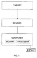
- FIGURE 1 is a diagrammatic view of a compressed symbology strain gage.
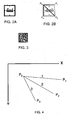
- FIGURE 2A shows a manufactured image configuration for a symbolic strain rosettes capable of serving as a target that satisfies the conditions for optically detecting strain when affixed to a surface undergoing load and deformation.
- FIGURE 2B shows the line segments and endpoints that define the symbolic strain rosette of FIGURE 2A .
- FIGURE 3 shows an overall image in the form of a Data Matrix symbol, in which is included a manufactured image configuration for symbolic strain rosettes capable of serving as a target that satisfies the conditions for optically detecting strain when the affixed to a surface undergoing load and deformation.
- FIGURE 4 shows three intersecting line segments that define a strain rosette.
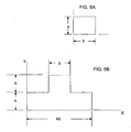
- FIGURE 5A shows a rectangular unit cell of a sub-image of a strain rosette.
- FIGURE 5B shows a T-shaped sub-image of a strain rosette.
- FIGURE 6A shows the SSR in the Data Matrix symbol of FIGURE 3 .
- FIGURE 6B shows the line segments and endpoints that define the symbolic strain rosette in the overall image shown in FIGURE 3 .
- FIGURE 7 is a sub-image of the strain rosette shown in FIGURE 6A .
- FIGURE 8 is a graph showing the range of applicability of the current technology and contrasts the technology with other methods of measuring strain.
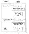
- FIGURE 9 shows the arrangement of FIGURES 9A and 9B .
- FIGURES 9A and 9B together are a high level flow diagram illustrating the algorithm followed by the computer program.
- FIGURE 1 there is shown diagrammatically a compressed symbology strain gage, comprising a target, a sensor, and a computer.
- the target is a symbolic strain rosette ("SSR")that has been manufactured or identified.
- SSR symbolic strain rosette
- FIGURES 2A and 3 Two examples of targets are shown in FIGURES 2A and 3.
- FIGURE 2A is an SSR that contains a corporate logo as part of the symbol geometry
- FIGURE 3 is a two-dimensional bar code that incorporates an SSR.
- Both SSRs are examples of targets that satisfy the conditions for optically detecting strain when affixed to a surface undergoing load and deformation.
- the SSR is defined in terms of its physical dimensions.
- Engineering strain is a measure of the relative change in length per unit length of the end points of a line segment connecting the points relative to a reference configuration of the SSR. This reference configuration is usually taken to be an undeformed position (zero loading).
- Any quantity in an SSR used as a strain gage must identify a geometrical property that can describe a point. An example of such a point is the centroid of a group of symbols as shown in FIGURE 3 . Any other point that can be uniquely identified can be considered as a property of the SSR for the purpose of strain measurement. Therefore, since the strain is measured for many possible configurations of an SSR, the end points of the same line must be identified for all possible configurations.
- a strain rosette is defined in terms of a pattern of three intersecting line segments, as shown in FIGURE 4 .
- the length of line segment 1 is measured by the end points P 0 and P 1
- the length of line segment 2 is measured by the end points P 0 and P 2
- the length of line segment 3 is measured by end points P 0 and P 3 .
- FIGURE 2A When the definition of strain is applied to the compressed symbol of the SSR, then it is necessary to identify the line segments by the location of the endpoints.
- the SSR shown in FIGURE 2A is defined by the corner points of its outside boundary.
- FIGURE 2B illustrates the line segments and endpoints for the SSR shown in FIGURE 2A .
- the end points are defined by the corner points of the square boundary.
- An SSR that is defined a posteriori can be identified either by centroidal coordinates or by some other convenient geometry that locates three intersecting line segments that define a strain rosette.
- the overall image is a "two dimensional bar code" of the type developed by NASA to identify and track space shuttle parts, and the SSR is part of the information contained in the two dimensional bar code.
- the bar code pattern can be used to encode inventory data or a history of the object to which it is attached, as described in "A White Paper on Two Dimensional Symbols,” by Paul Mathans et al. (CSPI Vision Systems 1996). However, the target does not have to contain any inventory or history data to be read.
- the "two-dimensional bar code” is more formally referred to as a matrix code, a term that applies to two-dimensional codes that code data based on the position of black modules within a matrix. All of the black modules are the same dimension and it is the positions of the modules that code the data.
- Data Matrix is a type of two-dimensional matrix code containing dark and light square data modules. It is designed to pack a lot of information in a very small space; a Data Matrix symbol can store between one and 3116 numeric or 2335 alphanumeric characters.
- a Data Matrix symbol has a finder pattern of two solid lines and two alternating dark and light lines on the perimeter of the symbol. These patterns are used to indicate both orientation and printing density of the symbol.
- a two-dimensional imaging device such as a CCD camera is used to scan the symbology.
- Data Matrix symbol The information in a Data Matrix symbol is encoded by absolute dot position rather than relative dot position. While a Data Matrix symbol is easily scalable between a 1-mil square to a 14-inch square, the actual limits are dependent on the fidelity of the marking device and the optics of the sensor. Data Matrix symbols can be used for small item marking applications using a wide variety of printing and marking technologies.
- the SSR is defined in terms of the centroidal coordinates of the sub-images of the bar code, as discussed in greater detail hereinafter, and can be monitored by the sensor to correlate the movement of the centroids of the sub-images of the SSR.
- the linear quantities that define the strain rosette can be created using linear-edged shapes or curved-edged shapes. Circles can be used to create curved-edged SSRs.
- the target can be associated with an object by any means that results in the deformation of the SSR with the deformation under load.
- the deformation of the SSR and the object must bear a one-to-one relationship.
- the target can be associated with an object for which strain is to be measured by applying it directly or indirectly to the surface of the object, or by identifying it in a pre-existing pattern that defines an SSR. Whether applied or identified, the target can be embedded in the object for which strain is to be measured.
- Examples of application of a target include, but are not limited to:
- Examples of identification of a target include, but are not limited to:
- Examples of embedding of a target include, but are not limited to:
- the target can naturally emit a detectable physical quantity, create a detectable physical quantity, or reflect a detectable physical quantity.
- the detectable physical quantity can be a signal in any portion of the electromagnetic spectrum (including the audio frequency range), or it can be a field such as a magnetic field.
- the detectable physical quantity can be a signal that can be characterized as a grayscale image that can be converted into a bitmap file. Sensors that will sense various detectable physical quantities, including all these signals and fields, are commercially available.
- the target is scalable, in that it can be produced and sensed on a scale ranging from microscopic to macroscopic.
- the compressed symbology strain gage is applicable to very large applications such as viewing a target on earth from space to determine displacements/strain of the earth's surface or subsurface strains. All that is required is to match the sensor to the size of the target image and the detectable physical quantity emitted by the target.
- FIGURE 7 shows the range of applicability of the compressed symbology strain gage and contrasts the compressed symbology strain gage with other methods of measuring strain.
- Another advantage of the compressed symbology strain gage is that the range of strain measurements is easily from 0 to at least 50%, which permits measurements of strain in elastic materials such as rubber and plastic. The potential exits to cover measurements at the nanoscale level.
- a third, and major advantage of the compressed symbology strain gage is that subsurface strains can be measured. Subsurface measurements can have special applications in man-made composites.
- the compressed symbology strain gage also can be used in the assessment of fatigue damage (accumulation) in critical areas of structures or components of devices subjected to cyclic or other loadings. This is accomplished by observing the area of a component under study over a selected period of time during the normal usage of the area. The data can then be used to predict failure of the component.
- the sensor observes the deformation of a target affixed to a surface or embedded in a material by capturing the total image of the target and transmitting it to the computer.
- the sensor is selected to be compatible with the detectable physical quantity emitted by the target and undertakes some pre-processing of the observed physical quantity to provide data representing the physical quantity to the computer.
- the input signal to the sensor may be a grayscale image that can be converted into a bitmap file, although other inputs can be accommodated.
- the computer conventionally comprises memory for storing programs and data and a processor for implementing the programs and processing the data, and is associated with a display for displaying data.
- the computer implements programs that (1) identify the SSR and the changes therein as a function of time and change in the load, (2) translate the changes in the SSR into strain, and (3) display it in a suitable format.
- the display of the data can take place in real time.
- the technology is scalable with respect to the size of the object under study.
- the SSR is monitored by optical, magnetic, electromagnetic, acoustic, or other sensor, as appropriate - at successive periods of time, either on a continuous time, at random times triggered by an external event ,or on a programmed time basis.
- the sub-images of the SSR are correlated over time to detect the movement of the centroids of the sub-images, and the movements are quantified and utilized in analytical expressions to determine strain in the directions of the coordinate system used corresponding to the plane of the surface under study.
- the movement of the centroids is detected by a program implemented by the computer , which identifies the SSR and its sub-images, correlates the sub-images of the SSR over time, determines the displacement of the centroids of the sub-images of the SSR, and utilizes the data obtained as input for strain equations as described hereinafter and to yield and display strain in two dimensions.
- the mathematical basis of the invention is the correlation of the movement of the centroids of sub-images defining the SSR.
- the sub-images can be any geometric shape.
- the sub-image consists of one unit cell, which is a rectangle having a height h and a width b .
- the unit cells can be combined into, for example, a T shape (shown in FIGURE 5B ) consisting of a large rectangle and a small rectangle arranged next to each other, where the small rectangle is a single unit cell and the large rectangle is made up of k unit cells, where k is an integer (i.e., the size of the large rectangle is an integer multiple of the size of the small rectangle).
- sub-image 100a is the reference and consists of one cell of the type shown in FIGURE 5A ;
- sub-images 100b, 100c, and 100d are complex sub-images of the type shown in FIGURE 5B , and primarily measure movement in the X direction;
- sub-image 100e which like sub-image 100a consists of a single cell, measures movement in the X and Y directions;
- sub-images 100f, 100g, and 100h are complex sub-images that measure movement in the Y direction.
- a minimum configuration requires the four corner sub-images, sub-images 100a, 100c, 100e, and 100g.
- sub-images 100a-100h form an over-determined set for the strain rosette.
- the centroidal coordinates for each sub-image shown in FIGURE 6A are measured from the origin of a local coordinate system.
- the centroidal coordinates are designated X c , Y c .
- X and Y are the global coordinates of a two-dimensional sub-image.
- Equations 12 and 13 can now be used to continue to explain by an example an optical method for strain determination.
- the deformation of the SSR and the deformation under load of the object to which it is applied or on which it is identified must bear a one-to-one relationship.
- a 5 x 5 pixel array is selected for each cell and the strain rosette will have a 100-pixel subset for each sub-image.
- the following calculations relate the change, ⁇ S, in the centroids of the sub-images, with the strain induced by loading the surface under study.
- an SSR can be devised for any coordinate system or can be identified by analysis of a pre-existing symbol or other pattern so that it can be used as a target.
- the movement of the centroids of the sub-images of the target can be utilized with the strain equations written for the coordinate system used to determine strain optically and the computer program is applicable to any coordinate system and sub-image geometric shape.
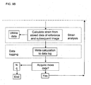
- the algorithm comprises three basic stages, image grabbing, strain analysis, and data logging; and utilizes two types of images, a reference image, acquired either without application of a load or with a reference load on the object for which strain is to be measured, and subsequent images, acquired after the reference image in the presence of a load or change to the load on the object.
- the image grabbing stage comprises the following steps:
- the sensor acquires the reference image and outputs data representing the reference image to the computer .
- a program or programs implemented by the computer then analyzes the reference image data to define an SSR, and concurrently displays the reference image, preferably in real time, on a computer monitor or other display device.
- the computer stores the analyzed reference image data.
- the sensor acquires a subsequent image and outputs data representing that subsequent image (that is, the current subsequent image) to the computer.
- Acquisition of subsequent images can take place either continuously or at predetermined intervals, or it can be triggered by an external event such as the application of a load.
- the number of subsequent images thus can range from one to thousands.
- the program analyzes it to define an SSR, and concurrently displays the corresponding subsequent image, preferably in real time, on a computer monitor or other display device (preferably on the same monitor or other display device on which the reference image is being displayed, to facilitate comparison).
- the computer stores the analyzed subsequent image data for the current subsequent image.
- the strain analysis stage takes place following the image grabbing stage, and is carried out each time a subsequent image is acquired.
- the computer calculates the strain from the stored reference image data and the stored subsequent image data for the current subsequent image, based on the changes in the SSR as a function of time and change in the load. Thus, a new strain calculation is made for each subsequent image.
- the strain calculation can then be utilized as a display, as well as providing information on fatigue damage or strain hysteresis for materials of known and unknown mechanical properties, providing advance notice of an approaching failure point for materials of known mechanical properties, extrapolating a failure point for a material of unknown mechanical properties, or based on collected damage accumulation data.
- the data logging stage takes place following each iteration of the strain analysis stage.
- the program gets the current results and writes them to a log file.
- FIGURES 9A and 9B are for purposes of illustration, and some changes can be made in the algorithm without affecting the results.
- the display of the reference and subsequent images can take place sequentially with the analysis of those images, as well as substantially concurrently; the acquisition and display of the reference and/or the subsequent images can be initiated by an external event; and images can be recorded during an event and stored for processing at a later time.
Landscapes
- Physics & Mathematics (AREA)
- General Physics & Mathematics (AREA)
- Investigating Strength Of Materials By Application Of Mechanical Stress (AREA)
- Length Measuring Devices By Optical Means (AREA)
- Force Measurement Appropriate To Specific Purposes (AREA)
- Measurement Of Force In General (AREA)
- Length Measuring Devices With Unspecified Measuring Means (AREA)
Abstract
Description
- The present invention relates to strain gages, and particularly to a strain gage that can measure strain directly, as well as assess fatigue damage.
- The strain rosette is a fundamental of analytical strain analysis, as explained in the engineering text "Theory of Elasticity" by Timoshenko and Goodier: The strains, or unit elongations, on a surface are usually most conveniently measured by means of electric-resistance strain gages. The use of these gages is simple when the principal directions are known. One gage is placed along each principal direction and an analog of strain is measured and calibrated to indicate strains ε1, ε2. The principal stresses σ1, σ2 can then be calculated from Hooke's law, with σx = σ1, and σy = σ2, and with σz = 0 on the assumption that there is no stress acting on the surface to which the gauges are attached. Then:


- When the principal directions are not known in advance, three measurements are needed. Thus, the state of strain is completely determined if εx, εy, and vxy can be measured. But since strain gages, and particularly electrical resistance strain gages, measure extensions, and not shearing strain directly, it is convenient to measure the unit elongations in three directions at the point. Such a set of electrical resistance gages is commonly called a "strain rosette" because the gages are arranged in the pattern of a strain rosette; however, "strain rosette" is used here in its original sense (as set forth in the definitions below), rather than to denote a configuration of electrical resistance gages.
- A Mohr strain circle can be constructed for a strain rosette, and the differential equations of equilibrium for a small rectangular block of edges h, k, and unity can be derived. If X, Y denote the components of body force per unit volume, the equation of equilibrium for forces in the x-direction is

where σx, σy, and τxy refer to the point x, y, the mid-point of the small rectangular block, and where (δx)1, (δx)3, etc. denote the values at the mid-points of the faces of the rectangle. The dividing by hk,
- If the block is taken smaller and smaller, that is, h - 0, h - 0, the limit of [(σx)1, - (σx)3]/k is ∂σx/∂x by the definition of such a derivative. Similarly, [(τxy)2, -(τxy)4]/k is ∂τxy/∂y. The equation of equilibrium for forces in the y-direction is obtained in the same manner.
- Strain measurements made with electrical resistance gages in a rosette pattern are subject to the same errors (thermal output, transverse sensitivity, leadwire resistance effects, etc.) as those made with single-element strain gages.
- Letters Patent of
U.S. Patent No. 4,591,996 to Vachon and Ranson discloses optical strain measurement using correlation of speckle patterns reflected from an illuminated optically diffuse surface. The speckle patterns are random signals that are characteristics of the surface area under investigation. Each area of the surface has a unique pattern just as each individual has unique facial characteristics. Correlating the movement of the speckle pattern of a surface undergoing deformation using machine vision to record the speckle pattern movement as a function of time permits the determination of strain. -
U.S. Patent No. 4,008,960 to Reytblatt discloses a photoelastic strain gauge coating comprising a sheet of photoelastic material of predetermined shape having a multiplicity of minute discontinuities or sets of discontinuities arranged in a predetermined grid. The predetermined shape and grid, together with boundary devices, provide a standard format to enable use of supporting computer programs. The coating is bonded to the workpiece surface to be analyzed, and then illuminated bipolarized light and photographed. The photograph is then magnified greatly to enable examination seriatim of the patterns at and about each discontinuity or set of discontinuities. The data thus obtained is processed, using the supporting computer programs to obtain a strain field of the portion of the workpiece covered by the coating. The technique of photoelastic coating requires that the birefringent material be bonded to a structure where stresses are to be measured when the structure is subjected to applied loads. Further, although Reytblatt describes a photoelastic strain gage, only the directions and differences in principal strains can be determined. Strain cannot be measured directly; it must be inferred from the stress measurements. - Technical efforts have continued in the area of optical correlation of surface images to detect strain. Specifically, these efforts include, among other things: (1) optical detection of edges of images on surfaces as well as optical detection of edges of surfaces, (2) optical correlation of dot and other geometric patterns applied to surfaces, and (3) optical correlation of the movement of centroids of geometric patterns applied to surfaces. All of these analytical and experimental efforts have been directed to optical detection of strain.
- Single-element strain gages, electrical resistance gages arranged in a rosette pattern employ analog techniques, rather than measuring strain directly. Previous optical correlation techniques calculate strains using a convolution integral, and also do not measure strain directly.
- It is to the provision of a strain gage that can measure strain directly, as well as assessing fatigue damage, that the present invention is directed.
- Definitions and abbreviations used herein are as follows:
- Compressed - the compression of data within a symbol.
- Compressed symbol - a compressed symbology symbol.
- Compressed symbology - a general term used to describe a category of identification symbols that can be encoded with information, can be marked directly on the surface of a product, or applied to a film or other medium that is in turn bonded to the surface of a product, and can be scaled up or down to fit the application. Their structure is usually a matrix format, resembling a checkerboard.
- Edge - a dramatic change in pixel brightness values between regions. It is the point or points that has or have the greatest amount of contrast difference (change in intensity values) between pixels. See "Application of Data Matrix Identification Symbols to Aerospace Parts Using Direct Part Marking Methods/Techniques," NASA-HDBK-6003, July 2, 2001.
- Fatigue damage (accumulated damage) - the cumulative or irreversible damage incurred in materials caused by cyclic application of stresses and environments resulting in degradation of load carrying capacity. See "Application of Data Matrix Identification Symbols to Aerospace Parts Using Direct Part Marking Methods/Techniques," NASA-HDBK-6003, July 2, 2001.
- Quiet zone - areas of high reflectance (spaces) surrounding a machine readable symbol. Quiet zone requirements may be found in application and symbology specifications. Sometimes called "Clear Area" or "Margin."
- Strain rosette - a pattern of intersecting lines on a surface along which linear strains are measured to find stresses at a point (stress at a point is a quantity calculated from data derived from the strain rosette).
- SSR - symbolic strain rosette.
- Stress at a point - a calculated quantity from the strain rosette data.
- Symbolic strain rosette - a strain rosette in the form of a compressed symbol that is defined in terms of its physical dimensions, and more particularly, of the end points of three intersecting line segments that define the strain rosette. The compressed symbol can be a two dimensional bar code matrix or other pattern in which the strain rosette is defined either a priori by manufacture or a posteriori by identification.
- Symbology - a machine-readable pattern composed of quiet zone, finder pattern, and symbol characters (which include special functions and error detection and/or correction characters) required by a particular symbology
- It is a primary object of the present invention to provide a strain gage that measures strain directly, as opposed to measuring strain by analog techniques.
- These and other objects of the invention are achieved by provision of a compressed symbology strain gage and a measuring method as defined by the
claims
The target comprises a symbolic strain rosette ("SSR"), and can be part of an overall image. - The target can be applied directly or indirectly to the surface of a body for which strain is to be measured, or identified in a pre-existing pattern that defines the SSR. The target can be identified by observing naturally occurring marks or objects that define an SSR on a macroscopic or microscopic scale. Whether applied or identified, it can be covered by paint or other material. The target can also be embedded in the object for which strain is to be measured.
- In one embodiment of the invention, the SSR can be a strain rosette contained in a "two dimensional bar code," particularly a Data Matrix symbol.
- In another embodiment of the invention, the SSR can be identified in a pre-existing overall image.
- There are an infinite number of image configurations for the SSR. The SSR can be composed of a plurality of sub-images, each of which has a centroid, and can be monitored by the sensor to correlate the movement of the centroids of the sub-images of the SSR.
- The specific SSR must be associated with an object (by application or identification) in such a way that the deformation of the SSR and the deformation under load of the object with which it is associated (that is, to which it is applied or on which it is identified) bear a one-to-one relationship. The target comprising the SSR is monitored -- by an optical, magnetic, electromagnetic, acoustic, or other sensor, as appropriate -- either on a continuous basis, at random times triggered by an external event, or at pre-determined intervals. The images of the SSR are correlated to detect the movement of the centroids of the sub-images of the SSR being used or the sub-images identified in a non-SSR symbol, the movements are quantified and utilized in analytical expressions to determine strain in the directions of the coordinate system used corresponding to the plane of the surface under study. The movement of centroids is detected by a computer-implemented program which identifies the SSR, correlates the specific symbol/sub images (constituting the SSR) used, determines the displacement of the centroids of the sub-images of the SSR, and utilizes the data obtained as input for strain equations as described hereinafter and to yield and display strain in two dimensions.
- The target can naturally emit a detectable physical quantity (as, for example, a material that naturally emits a magnetic field), emit a detectable physical quantity upon external stimulation (as, for example, a material that creates a magnetic field when subjected to a current or a material that emits light when stimulated by an electric field), or reflect a detectable physical quantity; and the physical quantity can be a signal in any bandwidth of the electromagnetic spectrum (including the audio frequency range), or it can be a field such as a magnetic field. The target is scalable, in that it can be produced and sensed on a scale ranging from microscopic to macroscopic.
- The sensor observes the deformation of a target affixed to a surface or embedded in a material or an object, and the deformation of the target, if any, over time. The sensor is selected to be compatible with the detectable physical quantity emitted by the target and undertakes some pre-processing of the observed physical quantity to provide data representing the physical quantity to the computer. The computer implements programs that analyze the data, and store and display the data and strain calculation in real time as the object under study is submitted to loading resulting in strain. The technology is scalable with respect to the size of the object under study.
- The method employs correlation of the sub-images of one of several SSRs or the correlation of identified sub-images in a non-SSR symbol applied to a surface. The correlation can be optical, acoustical, magnetic, or electromagnetic.
- Other objects, features and advantages of the present invention will be apparent to those skilled in the art upon a reading of this specification including the accompanying drawings.
- The invention is better understood by reading the following Detailed Description of the Preferred Embodiments with reference to the accompanying drawing figures, in which like reference numerals refer to like elements throughout, and in which:
-
FIGURE 1 is a diagrammatic view of a compressed symbology strain gage. -
FIGURE 2A shows a manufactured image configuration for a symbolic strain rosettes capable of serving as a target that satisfies the conditions for optically detecting strain when affixed to a surface undergoing load and deformation. -
FIGURE 2B shows the line segments and endpoints that define the symbolic strain rosette ofFIGURE 2A . -
FIGURE 3 shows an overall image in the form of a Data Matrix symbol, in which is included a manufactured image configuration for symbolic strain rosettes capable of serving as a target that satisfies the conditions for optically detecting strain when the affixed to a surface undergoing load and deformation. -
FIGURE 4 shows three intersecting line segments that define a strain rosette. -
FIGURE 5A shows a rectangular unit cell of a sub-image of a strain rosette. -
FIGURE 5B shows a T-shaped sub-image of a strain rosette. -
FIGURE 6A shows the SSR in the Data Matrix symbol ofFIGURE 3 . -
FIGURE 6B shows the line segments and endpoints that define the symbolic strain rosette in the overall image shown inFIGURE 3 . -
FIGURE 7 is a sub-image of the strain rosette shown inFIGURE 6A . -
FIGURE 8 is a graph showing the range of applicability of the current technology and contrasts the technology with other methods of measuring strain. -
FIGURE 9 shows the arrangement ofFIGURES 9A and9B . -
FIGURES 9A and9B together are a high level flow diagram illustrating the algorithm followed by the computer program. - In describing preferred embodiments of the present invention illustrated in the drawings, specific terminology is employed for the sake of clarity.
- Referring now to
FIGURE 1 , there is shown diagrammatically a compressed symbology strain gage, comprising a target, a sensor, and a computer. The target is a symbolic strain rosette ("SSR")that has been manufactured or identified. There are an infinite number of image configurations for the SSR. Two examples of targets are shown inFIGURES 2A and 3. FIGURE 2A is an SSR that contains a corporate logo as part of the symbol geometry, whileFIGURE 3 is a two-dimensional bar code that incorporates an SSR. Both SSRs are examples of targets that satisfy the conditions for optically detecting strain when affixed to a surface undergoing load and deformation. - Whether manufactured or identified, the SSR is defined in terms of its physical dimensions. Engineering strain is a measure of the relative change in length per unit length of the end points of a line segment connecting the points relative to a reference configuration of the SSR. This reference configuration is usually taken to be an undeformed position (zero loading). Any quantity in an SSR used as a strain gage must identify a geometrical property that can describe a point. An example of such a point is the centroid of a group of symbols as shown in
FIGURE 3 . Any other point that can be uniquely identified can be considered as a property of the SSR for the purpose of strain measurement. Therefore, since the strain is measured for many possible configurations of an SSR, the end points of the same line must be identified for all possible configurations. - A strain rosette is defined in terms of a pattern of three intersecting line segments, as shown in
FIGURE 4 . The length ofline segment 1 is measured by the end points P0 and P1, the length ofline segment 2 is measured by the end points P0 and P2, and the length ofline segment 3 is measured by end points P0 and P3. - When the definition of strain is applied to the compressed symbol of the SSR, then it is necessary to identify the line segments by the location of the endpoints. The SSR shown in
FIGURE 2A is defined by the corner points of its outside boundary.FIGURE 2B illustrates the line segments and endpoints for the SSR shown inFIGURE 2A . The end points are defined by the corner points of the square boundary. - An SSR that is defined a posteriori can be identified either by centroidal coordinates or by some other convenient geometry that locates three intersecting line segments that define a strain rosette.
- In one embodiment of the invention, as shown in
FIGURE 3 , the overall image is a "two dimensional bar code" of the type developed by NASA to identify and track space shuttle parts, and the SSR is part of the information contained in the two dimensional bar code. The bar code pattern can be used to encode inventory data or a history of the object to which it is attached, as described in "A White Paper on Two Dimensional Symbols," by Paul Mathans et al. (CSPI Vision Systems 1996). However, the target does not have to contain any inventory or history data to be read. - The "two-dimensional bar code" is more formally referred to as a matrix code, a term that applies to two-dimensional codes that code data based on the position of black modules within a matrix. All of the black modules are the same dimension and it is the positions of the modules that code the data. Data Matrix is a type of two-dimensional matrix code containing dark and light square data modules. It is designed to pack a lot of information in a very small space; a Data Matrix symbol can store between one and 3116 numeric or 2335 alphanumeric characters. A Data Matrix symbol has a finder pattern of two solid lines and two alternating dark and light lines on the perimeter of the symbol. These patterns are used to indicate both orientation and printing density of the symbol. A two-dimensional imaging device such as a CCD camera is used to scan the symbology.
- The information in a Data Matrix symbol is encoded by absolute dot position rather than relative dot position. While a Data Matrix symbol is easily scalable between a 1-mil square to a 14-inch square, the actual limits are dependent on the fidelity of the marking device and the optics of the sensor. Data Matrix symbols can be used for small item marking applications using a wide variety of printing and marking technologies.
- Additional information regarding Data Matrix code is disclosed in
U.S. Patents Nos. 4,939,354 ;5,053,609 ;5,124,536 . - In the case of the SSR incorporated into the two-dimensional bar code as shown in
FIGURE 3 , the SSR is defined in terms of the centroidal coordinates of the sub-images of the bar code, as discussed in greater detail hereinafter, and can be monitored by the sensor to correlate the movement of the centroids of the sub-images of the SSR. - In another embodiment, the linear quantities that define the strain rosette can be created using linear-edged shapes or curved-edged shapes. Circles can be used to create curved-edged SSRs.
- The target can be associated with an object by any means that results in the deformation of the SSR with the deformation under load. The deformation of the SSR and the object must bear a one-to-one relationship. The target can be associated with an object for which strain is to be measured by applying it directly or indirectly to the surface of the object, or by identifying it in a pre-existing pattern that defines an SSR. Whether applied or identified, the target can be embedded in the object for which strain is to be measured.
- Examples of application of a target include, but are not limited to:
- 1. Application to a medium such as a polymide film that is bonded, for example by gluing, to the surface of the object for which strain is to be measured (indirect application);
- 2. Etching on a surface (direct application);
- 3. Painting on surface (direct application); and
- 4. Printing on a surface (direct application).
- Examples of identification of a target include, but are not limited to:
- 1. Identification by observing naturally-occurring surface features of the object that define an SSR on a macroscopic or microscopic scale (for example, features on the surface of the earth).
- 2. Identification by observing naturally-occurring subsurface features of the object that define an SSR on a macroscopic or microscopic scale (for example, a fossil buried in the earth).
- 3. Identification by observing manmade surface features of the object that define an SSR on a macroscopic or microscopic scale (for example, a collection of components).
- 4. Identification by observing manmade subsurface features of the object that define an SSR on a macroscopic or microscopic scale(for example, structural elements of a spacecraft covered with a skin, the structural elements of a bridge covered with a skin, or the structural elements of a building having a surface opaque in the visible spectrum).
- Examples of embedding of a target include, but are not limited to:
- 1. Embedding in the object to be studied when the object is being formed;
- 2. Identification of naturally occurring or manufactured subsurface features;
- 3. Covering with an overlying material, such as one or more layers of paint; and
- 4. Implanting in a human body, in a body part or an implant. For example, if the target is affixed to a critical area of a hip joint or a hip implant, or to an artificial heart valve, the target can be viewed through the tissue surrounding the target by an x-ray sensor, and the strain and fatigue damage to the associated body part or implant can be assessed over time.
- The target can naturally emit a detectable physical quantity, create a detectable physical quantity, or reflect a detectable physical quantity. The detectable physical quantity can be a signal in any portion of the electromagnetic spectrum (including the audio frequency range), or it can be a field such as a magnetic field. The detectable physical quantity can be a signal that can be characterized as a grayscale image that can be converted into a bitmap file. Sensors that will sense various detectable physical quantities, including all these signals and fields, are commercially available.
- The target is scalable, in that it can be produced and sensed on a scale ranging from microscopic to macroscopic. Thus, the compressed symbology strain gage is applicable to very large applications such as viewing a target on earth from space to determine displacements/strain of the earth's surface or subsurface strains. All that is required is to match the sensor to the size of the target image and the detectable physical quantity emitted by the target.
FIGURE 7 shows the range of applicability of the compressed symbology strain gage and contrasts the compressed symbology strain gage with other methods of measuring strain. - One advantage of the compressed symbology strain gage is that strain is measured directly, as opposed to being inferred from secondary measurements using analog techniques; thus making possible an explicit detectable "reading" of normal and shear strain components. This in turn leads to greater accuracy and reduced system errors.
- Another advantage of the compressed symbology strain gage is that the range of strain measurements is easily from 0 to at least 50%, which permits measurements of strain in elastic materials such as rubber and plastic. The potential exits to cover measurements at the nanoscale level.
- A third, and major advantage of the compressed symbology strain gage is that subsurface strains can be measured. Subsurface measurements can have special applications in man-made composites.
- The compressed symbology strain gage also can be used in the assessment of fatigue damage (accumulation) in critical areas of structures or components of devices subjected to cyclic or other loadings. This is accomplished by observing the area of a component under study over a selected period of time during the normal usage of the area. The data can then be used to predict failure of the component.
- The sensor observes the deformation of a target affixed to a surface or embedded in a material by capturing the total image of the target and transmitting it to the computer. The sensor is selected to be compatible with the detectable physical quantity emitted by the target and undertakes some pre-processing of the observed physical quantity to provide data representing the physical quantity to the computer. In the case of an SSR that can be monitored optically, such as an SSR incorporated into a Data Matrix symbol, the input signal to the sensor may be a grayscale image that can be converted into a bitmap file, although other inputs can be accommodated.
- The computer conventionally comprises memory for storing programs and data and a processor for implementing the programs and processing the data, and is associated with a display for displaying data. As the object under study is submitted to loading resulting in strain, the computer implements programs that (1) identify the SSR and the changes therein as a function of time and change in the load, (2) translate the changes in the SSR into strain, and (3) display it in a suitable format. The display of the data can take place in real time. The technology is scalable with respect to the size of the object under study.
- The SSR is monitored by optical, magnetic, electromagnetic, acoustic, or other sensor, as appropriate - at successive periods of time, either on a continuous time, at random times triggered by an external event ,or on a programmed time basis. The sub-images of the SSR are correlated over time to detect the movement of the centroids of the sub-images, and the movements are quantified and utilized in analytical expressions to determine strain in the directions of the coordinate system used corresponding to the plane of the surface under study. The movement of the centroids is detected by a program implemented by the computer , which identifies the SSR and its sub-images, correlates the sub-images of the SSR over time, determines the displacement of the centroids of the sub-images of the SSR, and utilizes the data obtained as input for strain equations as described hereinafter and to yield and display strain in two dimensions.
- The explanation that follows of the technical basis of the present invention utilizes a Cartesian coordinate system and a specific sub-image shape for illustration. However, any coordinate system and any geometric sub-image shape may be used as long as the coordinate system is consistent for the sub images of the SSR and analyses of the strain equations.
- The mathematical basis of the invention is the correlation of the movement of the centroids of sub-images defining the SSR. The sub-images can be any geometric shape. In the example shown in
FIGURE 5A , which is for purposes of illustration only, the sub-image consists of one unit cell, which is a rectangle having a height h and a width b. Where the sub-image comprises more than one unit cell, the unit cells can be combined into, for example, a T shape (shown inFIGURE 5B ) consisting of a large rectangle and a small rectangle arranged next to each other, where the small rectangle is a single unit cell and the large rectangle is made up of k unit cells, where k is an integer (i.e., the size of the large rectangle is an integer multiple of the size of the small rectangle). - Taking as an example a target in which the SSR comprises a Data Matrix symbol, the pattern shown in
FIGURE 6A defined by the sub-images 100a-100h forms the elements of a strain rosette. In this example, sub-image 100a is the reference and consists of one cell of the type shown inFIGURE 5A ; sub-images 100b, 100c, and 100d are complex sub-images of the type shown inFIGURE 5B , and primarily measure movement in the X direction; sub-image 100e, which like sub-image 100a consists of a single cell, measures movement in the X and Y directions; and sub-images 100f, 100g, and 100h are complex sub-images that measure movement in the Y direction. A minimum configuration requires the four corner sub-images, sub-images 100a, 100c, 100e, and 100g. In the example, sub-images 100a-100h form an over-determined set for the strain rosette. - The centroidal coordinates for each sub-image shown in
FIGURE 6A are measured from the origin of a local coordinate system. The centroidal coordinates are designated X c, Y c. The centroids for the rectangular sub-image of the type shown inFIGURE 5A are:

The centroids for the complex (compound rectangular) sub-image of the type shown inFIGURE 5B are:

Therefore:


- It can be shown that as k gets large, (k+3) ≅ k, and (k+1) ≅ k. Thus, Yc ≅ ½ h and the contribution of the smaller rectangle in the complex sub-image is small.
- With reference to
FIGURE 7 , X and Y are the global coordinates of a two-dimensional sub-image. The computer will implement a scanning algorithm that locates the corner of each sub-image. If the sub-image of an SSR is denoted by its ith number, then the centroid of each sub-image is denoted as:

where Xic and Yic are the global coordinates of the centroid of the symbol, and Xc and Yc are the local centroidal coordinates of each sub-image of the symbol. For a rectangular sub-image:

and for a compound rectangular sub-image of the symbol such as the sub-image shown inFIGURE 7 :

- Equations 12 and 13, as an example, can now be used to continue to explain by an example an optical method for strain determination. As previously discussed, the deformation of the SSR and the deformation under load of the object to which it is applied or on which it is identified must bear a one-to-one relationship. Using the example of the SSR incorporated in the Data Matrix symbol of
FIGURE 3 , a 5 x 5 pixel array is selected for each cell and the strain rosette will have a 100-pixel subset for each sub-image. The following calculations relate the change, ΔS, in the centroids of the sub-images, with the strain induced by loading the surface under study.


where l and m are direction cosines and l = m = .707 in this example for the coordinate system and symbol used. - The above relationships allow the determination of εxx, εyy, εxy from the SSR used in this example. Similarly, an SSR can be devised for any coordinate system or can be identified by analysis of a pre-existing symbol or other pattern so that it can be used as a target. The movement of the centroids of the sub-images of the target can be utilized with the strain equations written for the coordinate system used to determine strain optically and the computer program is applicable to any coordinate system and sub-image geometric shape.
- Referring now to
FIGURES 9A and9B together, there are shown a high level flow diagram illustrating the algorithm followed by the computer programs. The algorithm comprises three basic stages, image grabbing, strain analysis, and data logging; and utilizes two types of images, a reference image, acquired either without application of a load or with a reference load on the object for which strain is to be measured, and subsequent images, acquired after the reference image in the presence of a load or change to the load on the object. - The image grabbing stage comprises the following steps: The sensor acquires the reference image and outputs data representing the reference image to the computer . A program or programs implemented by the computer then analyzes the reference image data to define an SSR, and concurrently displays the reference image, preferably in real time, on a computer monitor or other display device. Following the analysis step, the computer stores the analyzed reference image data. Once the reference image has been acquired, analyzed, and stored, the sensor acquires a subsequent image and outputs data representing that subsequent image (that is, the current subsequent image) to the computer.
- Acquisition of subsequent images can take place either continuously or at predetermined intervals, or it can be triggered by an external event such as the application of a load. The number of subsequent images thus can range from one to thousands. Once data representing a subsequent image is input to the computer, the program analyzes it to define an SSR, and concurrently displays the corresponding subsequent image, preferably in real time, on a computer monitor or other display device (preferably on the same monitor or other display device on which the reference image is being displayed, to facilitate comparison). Following the analysis step, the computer stores the analyzed subsequent image data for the current subsequent image.
- The strain analysis stage takes place following the image grabbing stage, and is carried out each time a subsequent image is acquired. In the strain analysis stage, the computer calculates the strain from the stored reference image data and the stored subsequent image data for the current subsequent image, based on the changes in the SSR as a function of time and change in the load. Thus, a new strain calculation is made for each subsequent image. The strain calculation can then be utilized as a display, as well as providing information on fatigue damage or strain hysteresis for materials of known and unknown mechanical properties, providing advance notice of an approaching failure point for materials of known mechanical properties, extrapolating a failure point for a material of unknown mechanical properties, or based on collected damage accumulation data.
- The data logging stage takes place following each iteration of the strain analysis stage. In the data logging stage, the program gets the current results and writes them to a log file.
- As will be appreciated by those of skill in the art, the flow diagram of
FIGURES 9A and9B is for purposes of illustration, and some changes can be made in the algorithm without affecting the results. For example, the display of the reference and subsequent images can take place sequentially with the analysis of those images, as well as substantially concurrently; the acquisition and display of the reference and/or the subsequent images can be initiated by an external event; and images can be recorded during an event and stored for processing at a later time. - Modifications and variations of the above-described embodiments of the present invention are possible, as appreciated by those skilled in the art in light of the above teachings.
Claims (10)
- A compressed symbology strain gage for measuring at least one of strain and fatigue damage of a body comprising:a target for emitting a detectable physical quantity; the target comprising a symbolic strain rosette in the form of a compressed symbol that is defined in terms of the end points of three intersecting line segments that define a strain rosette, wherein the compressed symbol is an identification symbol in a matrix format that can be encoded with information, that can be marked directly on the surface of a product, or applied to a film or other medium bonded to the surface of a product;sensor means for detecting changes in the target when a body with which the target is associated is subjected to a load, wherein the target is associated with the body in such a way that deformation of the symbolic strain rosette and deformation under load of the body bear a one-to-one relationship; andmeans for calculating strain based on changes in the target when the body is subjected to a load,where the sensor means is adapted to pre-process the detectable physical quantity emitted by the target and to output data representing the physical quantity, the sensor means being compatible with the detectable physical quantity;
where the compressed symbology strain gage further comprises means for analyzing the data output by the sensor means to define the symbolic strain rosette; and means for calculating the strain on the body directly, based on the pre-processed and analyzed data. - A method of measuring at least one of strain and fatigue damage on a body directly, comprising the steps of:detecting changes in a target emitting a detectable physical quantity when a body with which the target is associated is subjected to a load; andcalculating strain based on changes in the target when the body is subjected to a load,wherein the target is a symbolic strain rosette and is associated with the body in such a way that deformation of the symbolic strain rosette and deformation under load of the body bear a one-to-one relationship and the symbolic strain rosette is in the form of a compressed symbol that is defined in terms of the end points of three intersecting line segments that define a strain rosette,
wherein the compressed symbol is an identification symbol in a matrix format that can be encoded with information, that can be marked directly on the surface of a product, or applied to a film or other medium bonded to the surface of a product, the changes in the symbolic strain rosette are identified as a function of time and change in the load applied to the body; and the changes in the symbolic strain rosette are translated into a direct measurement of strain. - The method of claim 2, characterized in that the strain rosette is manufactured and the target is associated with the body by applying the strain rosette to the body.
- The method of claim 2, characterized in that the strain rosette is identified in a pre-existing pattern.
- The compressed symbology strain gage of claim 1, characterized in that the strain rosette is defined by manufacture.
- The compressed symbology strain gage of claim 5, characterized in that the strain rosette is contained in a two dimensional bar code.
- The compressed symbology strain gage of claim 6, characterized in that the two dimensional bar code is a Data Matrix symbol.
- The compressed symbology strain gage of claim 1, characterized in that the target is identified in a pre-existing pattern that defines the strain rosette.
- The compressed symbology strain gage of claim 1, characterized in that it further comprises means for utilizing the strain calculation to provide information on fatigue damage or strain hysteresis for materials of known and unknown mechanical properties, to provide advance notice of an approaching failure point for materials of known mechanical properties, or to extrapolate a failure point for a material of unknown mechanical properties, or based on collected damage accumulation data.
- The method of claim 2, characterized in that it further comprises the step of utilizing the strain calculation to provide information on fatigue damage or strain hysteresis for materials of known and unknown mechanical properties, to provide advance notice of an approaching failure point for materials of known mechanical properties, or to extrapolate a failure point for a material of unknown mechanical properties, or based on collected damage accumulation data.
Applications Claiming Priority (3)
| Application Number | Priority Date | Filing Date | Title |
|---|---|---|---|
| US10/223,680 US6934013B2 (en) | 2002-08-20 | 2002-08-20 | Compressed symbology strain gage |
| US223680 | 2002-08-20 | ||
| PCT/US2003/022136 WO2004018965A1 (en) | 2002-08-20 | 2003-07-16 | Compressed symbology strain gauge |
Publications (2)
| Publication Number | Publication Date |
|---|---|
| EP1535025A1 EP1535025A1 (en) | 2005-06-01 |
| EP1535025B1 true EP1535025B1 (en) | 2008-12-10 |
Family
ID=31886679
Family Applications (1)
| Application Number | Title | Priority Date | Filing Date |
|---|---|---|---|
| EP03792970A Expired - Lifetime EP1535025B1 (en) | 2002-08-20 | 2003-07-16 | Compressed symbology strain gauge |
Country Status (8)
| Country | Link |
|---|---|
| US (1) | US6934013B2 (en) |
| EP (1) | EP1535025B1 (en) |
| JP (1) | JP2005536739A (en) |
| AT (1) | ATE417243T1 (en) |
| AU (1) | AU2003251929A1 (en) |
| DE (1) | DE60325228D1 (en) |
| HK (1) | HK1078928A1 (en) |
| WO (1) | WO2004018965A1 (en) |
Families Citing this family (21)
| Publication number | Priority date | Publication date | Assignee | Title |
|---|---|---|---|---|
| US6874370B1 (en) | 2004-07-15 | 2005-04-05 | Reginald I. Vachon | Finite element analysis fatigue gage |
| US7477995B2 (en) * | 2005-02-03 | 2009-01-13 | Direct Measurements Inc. | Optical linear strain gage |
| US7533818B2 (en) * | 2005-06-28 | 2009-05-19 | Direct Measurements Inc. | Binary code symbol for non-linear strain measurement and apparatus and method for analyzing and measuring strain therewith |
| US8459567B2 (en) | 2006-08-17 | 2013-06-11 | Direct Measurements, Inc. | Non-linear strain gage incorporating a nested binary code symbol |
| US8322627B2 (en) * | 2006-08-17 | 2012-12-04 | Direct Measurements, Inc. | Nested binary code symbol |
| EP2126712A4 (en) * | 2007-02-23 | 2014-06-04 | Direct Measurements Inc | Differential non-linear strain measurement using binary code symbol |
| US20090192731A1 (en) * | 2008-01-24 | 2009-07-30 | Halliburton Energy Services, Inc. | System and Method for Monitoring a Health State of Hydrocarbon Production Equipment |
| EP2438552A4 (en) * | 2009-03-24 | 2017-08-23 | General Electric Company | Directly applied read and transmit - digital strain encoder and digital load cell |
| US8600147B2 (en) * | 2009-06-03 | 2013-12-03 | The United States of America as represented by the Secreatary of the Navy | System and method for remote measurement of displacement and strain fields |
| US20110106459A1 (en) * | 2009-10-29 | 2011-05-05 | Northrop Grumman Corporation | In-situ optical crack measurement using a dot pattern |
| US9046353B2 (en) * | 2011-08-02 | 2015-06-02 | The United States Of America As Represented By The Secretary Of The Navy | System and method for remote full field three-dimensional displacement and strain measurements |
| JP6139678B2 (en) * | 2012-07-19 | 2017-05-31 | スリーエム イノベイティブ プロパティズ カンパニー | Determination of elastic bandage elongation |
| US9311566B2 (en) | 2012-08-03 | 2016-04-12 | George Mason Research Foundation, Inc. | Method and system for direct strain imaging |
| WO2014178080A1 (en) * | 2013-05-03 | 2014-11-06 | Indian Council Of Medical Research | A non-contact method for measurement of strain profile at a location interposed within a soft deformable object with dynamic evolution of the strain under dynamic loading or fracture of the object |
| US9953408B2 (en) * | 2015-11-16 | 2018-04-24 | General Electric Company | Methods for monitoring components |
| US10024760B2 (en) * | 2015-12-17 | 2018-07-17 | General Electric Company | Methods for monitoring turbine components |
| US20170176269A1 (en) * | 2015-12-17 | 2017-06-22 | General Electric Company | Components with array-based strain sensors and methods for monitoring the same |
| JP6848281B2 (en) * | 2016-09-12 | 2021-03-24 | 大日本印刷株式会社 | Displacement amount measuring device and displacement amount measuring system |
| JP6883767B2 (en) * | 2017-02-28 | 2021-06-09 | パナソニックIpマネジメント株式会社 | Displacement measuring device and displacement measuring method |
| CN110514329A (en) * | 2019-08-08 | 2019-11-29 | 西安中星测控有限公司 | A kind of passive two-dimensional code load transducer and preparation method thereof |
| CN110514330A (en) * | 2019-08-08 | 2019-11-29 | 西安中星测控有限公司 | A kind of passive two-dimensional code pressure sensor and preparation method thereof |
Family Cites Families (31)
| Publication number | Priority date | Publication date | Assignee | Title |
|---|---|---|---|---|
| US3474237A (en) * | 1966-10-03 | 1969-10-21 | Automation Ind Inc | Strain gage rosette calculator |
| JPS51140656A (en) * | 1975-05-28 | 1976-12-03 | Sumitomo Metal Ind Ltd | Method and apparatus for measuring plastic deformation quantity of ste el sheet |
| US4008960A (en) * | 1975-08-18 | 1977-02-22 | Reytblatt Zinovy V | Photoelastic strain gauge coating and method of using same |
| US4050818A (en) * | 1975-09-10 | 1977-09-27 | The United States Of America As Represented By The Secretary Of The Air Force | Method for determining changes in spacing between two positions of interest |
| US4014613A (en) * | 1975-09-10 | 1977-03-29 | The United States Of America As Represented By The Secretary Of The Air Force | Method and apparatus for determining changes in spacing between two positions of interest |
| US4288852A (en) * | 1979-11-28 | 1981-09-08 | General Motors Corporation | Method and apparatus for automatically determining sheet metal strain |
| JPS57125803A (en) | 1981-01-29 | 1982-08-05 | Toyoda Gosei Co Ltd | Method for measuring strain of sample surface |
| US4591996A (en) * | 1981-05-18 | 1986-05-27 | Vachon Reginald I | Apparatus and method for determining stress and strain in pipes, pressure vessels, structural members and other deformable bodies |
| US5065331A (en) * | 1981-05-18 | 1991-11-12 | Vachon Reginald I | Apparatus and method for determining the stress and strain in pipes, pressure vessels, structural members and other deformable bodies |
| US4722600A (en) * | 1986-10-14 | 1988-02-02 | Chiang Fu Pen | Apparatus and method for measuring strain |
| US4939354A (en) * | 1988-05-05 | 1990-07-03 | Datacode International, Inc. | Dynamically variable machine readable binary code and method for reading and producing thereof |
| US5053609A (en) * | 1988-05-05 | 1991-10-01 | International Data Matrix, Inc. | Dynamically variable machine readable binary code and method for reading and producing thereof |
| US5124536A (en) * | 1988-05-05 | 1992-06-23 | International Data Matrix, Inc. | Dynamically variable machine readable binary code and method for reading and producing thereof |
| JP2607936B2 (en) * | 1988-10-05 | 1997-05-07 | 清水建設株式会社 | Crack measurement method for concrete members |
| US5047952A (en) * | 1988-10-14 | 1991-09-10 | The Board Of Trustee Of The Leland Stanford Junior University | Communication system for deaf, deaf-blind, or non-vocal individuals using instrumented glove |
| JP2676040B2 (en) * | 1989-01-28 | 1997-11-12 | 清水建設株式会社 | In-plane displacement measurement method for concrete members |
| US4969106A (en) * | 1989-02-27 | 1990-11-06 | Camsys, Inc. | Computerized method of determining surface strain distributions in a deformed body |
| US5671042A (en) * | 1992-02-18 | 1997-09-23 | Illinois Institute Of Technology | Holomoire strain analyzer |
| JPH05322557A (en) * | 1992-05-18 | 1993-12-07 | Saginomiya Seisakusho Inc | Lattice position data collection method for deformation observation |
| EP0651352A1 (en) * | 1993-10-27 | 1995-05-03 | Toshiba Engineering Corporation | Method and apparatus of inspecting surface irregularity of an object article |
| JPH07217622A (en) * | 1994-02-07 | 1995-08-15 | Hino Motors Ltd | Plasticity test method for rivet |
| US5531122A (en) * | 1994-02-28 | 1996-07-02 | Caterpillar Inc. | Fatigue analysis and warning system |
| US5726907A (en) * | 1995-07-31 | 1998-03-10 | Southwest Research Institute | Biaxial non-contacting strain measurement using machine vision |
| JPH09257465A (en) * | 1996-03-26 | 1997-10-03 | Toyota Motor Corp | Noncontact method for measuring strain of minute area |
| US6189386B1 (en) | 1997-12-05 | 2001-02-20 | Ford Global Technologies, Inc. | Method of using a microscopic digital imaging strain gauge |
| US5920383A (en) * | 1997-12-05 | 1999-07-06 | Ford Global Technologies, Inc. | Microscopic digital imaging strain gauge |
| JPH11173839A (en) * | 1997-12-16 | 1999-07-02 | Moritex Corp | Deformation state analyzer for structure or the like and data recorder and data analyzer used for the same |
| US6189356B1 (en) * | 2000-02-17 | 2001-02-20 | General Electric Company | Method and apparatus for peening |
| JP2002267422A (en) | 2001-03-09 | 2002-09-18 | Nippon Koei Power Systems Co Ltd | Method and device for crack detection |
| JP4683516B2 (en) * | 2001-05-16 | 2011-05-18 | 日本工営株式会社 | Crack displacement measurement method for structures using a digital camera |
| US6718269B2 (en) * | 2001-12-13 | 2004-04-06 | International Business Machines Corporation | Apparatus, program product and method of estimating the stress intensity factor ratio of a material |
-
2002
- 2002-08-20 US US10/223,680 patent/US6934013B2/en not_active Expired - Lifetime
-
2003
- 2003-07-16 AT AT03792970T patent/ATE417243T1/en not_active IP Right Cessation
- 2003-07-16 WO PCT/US2003/022136 patent/WO2004018965A1/en active Application Filing
- 2003-07-16 DE DE60325228T patent/DE60325228D1/en not_active Expired - Lifetime
- 2003-07-16 AU AU2003251929A patent/AU2003251929A1/en not_active Abandoned
- 2003-07-16 EP EP03792970A patent/EP1535025B1/en not_active Expired - Lifetime
- 2003-07-16 JP JP2004530826A patent/JP2005536739A/en active Pending
-
2005
- 2005-11-25 HK HK05110781.7A patent/HK1078928A1/en not_active IP Right Cessation
Also Published As
| Publication number | Publication date |
|---|---|
| WO2004018965B1 (en) | 2004-07-29 |
| AU2003251929A1 (en) | 2004-03-11 |
| US6934013B2 (en) | 2005-08-23 |
| JP2005536739A (en) | 2005-12-02 |
| HK1078928A1 (en) | 2006-03-24 |
| US20040036853A1 (en) | 2004-02-26 |
| DE60325228D1 (en) | 2009-01-22 |
| WO2004018965A1 (en) | 2004-03-04 |
| ATE417243T1 (en) | 2008-12-15 |
| EP1535025A1 (en) | 2005-06-01 |
Similar Documents
| Publication | Publication Date | Title |
|---|---|---|
| EP1535025B1 (en) | Compressed symbology strain gauge | |
| US7477995B2 (en) | Optical linear strain gage | |
| EP1782038B1 (en) | Finite element analysis fatigue gage | |
| EP1897036B1 (en) | Binary code symbol for non-linear strain measurement and method and apparatus for analyzing and measuring same | |
| US9046353B2 (en) | System and method for remote full field three-dimensional displacement and strain measurements | |
| CA2775040C (en) | Directly applied read and transmit - digital strain encoder and digital load cell | |
| JP6240206B2 (en) | Displacement field and strain field measurement method and material testing machine | |
| US20110106459A1 (en) | In-situ optical crack measurement using a dot pattern | |
| US8249832B2 (en) | Correlation of inspection information and computer-aided design data for structural assessment | |
| US20140037217A1 (en) | Method and system for direct strain imaging | |
| Pop et al. | Identification algorithm for fracture parameters by combining DIC and FEM approaches | |
| CN107131988A (en) | A kind of crash dummy chest pressure Distribution Test system and method for testing | |
| Turkan et al. | Terrestrial laser scanning-based bridge structural condition assessment | |
| US20240013044A1 (en) | Method for characterizing a part through non-destructive inspection | |
| Polli et al. | Automatic mapping of earthquake damage using post-event radar satellite data: The story goes on | |
| JP3312298B2 (en) | How to measure stress intensity factor | |
| Kohut et al. | Application of vision based damage detection for real civil engineering structure | |
| EP4028742B1 (en) | Apparatus for measuring soil contact stresses | |
| Wu et al. | Displacement sensing based on microscopic vision with high resolution and large measuring range | |
| Baraniecki et al. | Fatigue life stimation of structural element of MI-24 Helicopter | |
| MX2008000182A (en) | Binary code symbol and method and apparatus for analyzing and measuring same | |
| ALEMDAR et al. | DEFORMATION MEASUREMENT IN A STEEL BRIDGE SYSTEM BY USING IMAGE PROCESSING METHOD | |
| SANGSOBHON et al. | Fundamental Study on Fatigue Environmental Evaluation for Steel Girder Bridges Using Image Sensing | |
| Brown | Evaluation of a Novel Remote Displacement Sensor Prototype Using Video and Laser-Based Technology for Civil Infrastructure Applications | |
| Wirawan et al. | Development of Data Acquisition System of Moving Object for Landslide Monitoring System |
Legal Events
| Date | Code | Title | Description |
|---|---|---|---|
| PUAI | Public reference made under article 153(3) epc to a published international application that has entered the european phase |
Free format text: ORIGINAL CODE: 0009012 |
|
| 17P | Request for examination filed |
Effective date: 20050318 |
|
| AK | Designated contracting states |
Kind code of ref document: A1 Designated state(s): AT BE BG CH CY CZ DE DK EE ES FI FR GB GR HU IE IT LI LU MC NL PT RO SE SI SK TR |
|
| AX | Request for extension of the european patent |
Extension state: AL LT LV MK |
|
| DAX | Request for extension of the european patent (deleted) | ||
| REG | Reference to a national code |
Ref country code: HK Ref legal event code: DE Ref document number: 1078928 Country of ref document: HK |
|
| 17Q | First examination report despatched |
Effective date: 20060913 |
|
| GRAP | Despatch of communication of intention to grant a patent |
Free format text: ORIGINAL CODE: EPIDOSNIGR1 |
|
| GRAS | Grant fee paid |
Free format text: ORIGINAL CODE: EPIDOSNIGR3 |
|
| GRAA | (expected) grant |
Free format text: ORIGINAL CODE: 0009210 |
|
| AK | Designated contracting states |
Kind code of ref document: B1 Designated state(s): AT BE BG CH CY CZ DE DK EE ES FI FR GB GR HU IE IT LI LU MC NL PT RO SE SI SK TR |
|
| REG | Reference to a national code |
Ref country code: GB Ref legal event code: FG4D |
|
| REG | Reference to a national code |
Ref country code: CH Ref legal event code: EP |
|
| REG | Reference to a national code |
Ref country code: IE Ref legal event code: FG4D |
|
| REF | Corresponds to: |
Ref document number: 60325228 Country of ref document: DE Date of ref document: 20090122 Kind code of ref document: P |
|
| PG25 | Lapsed in a contracting state [announced via postgrant information from national office to epo] |
Ref country code: SI Free format text: LAPSE BECAUSE OF FAILURE TO SUBMIT A TRANSLATION OF THE DESCRIPTION OR TO PAY THE FEE WITHIN THE PRESCRIBED TIME-LIMIT Effective date: 20081210 Ref country code: NL Free format text: LAPSE BECAUSE OF FAILURE TO SUBMIT A TRANSLATION OF THE DESCRIPTION OR TO PAY THE FEE WITHIN THE PRESCRIBED TIME-LIMIT Effective date: 20081210 Ref country code: FI Free format text: LAPSE BECAUSE OF FAILURE TO SUBMIT A TRANSLATION OF THE DESCRIPTION OR TO PAY THE FEE WITHIN THE PRESCRIBED TIME-LIMIT Effective date: 20081210 |
|
| NLV1 | Nl: lapsed or annulled due to failure to fulfill the requirements of art. 29p and 29m of the patents act | ||
| REG | Reference to a national code |
Ref country code: HK Ref legal event code: GR Ref document number: 1078928 Country of ref document: HK |
|
| PG25 | Lapsed in a contracting state [announced via postgrant information from national office to epo] |
Ref country code: ES Free format text: LAPSE BECAUSE OF FAILURE TO SUBMIT A TRANSLATION OF THE DESCRIPTION OR TO PAY THE FEE WITHIN THE PRESCRIBED TIME-LIMIT Effective date: 20090321 Ref country code: EE Free format text: LAPSE BECAUSE OF FAILURE TO SUBMIT A TRANSLATION OF THE DESCRIPTION OR TO PAY THE FEE WITHIN THE PRESCRIBED TIME-LIMIT Effective date: 20081210 Ref country code: BG Free format text: LAPSE BECAUSE OF FAILURE TO SUBMIT A TRANSLATION OF THE DESCRIPTION OR TO PAY THE FEE WITHIN THE PRESCRIBED TIME-LIMIT Effective date: 20090310 Ref country code: BE Free format text: LAPSE BECAUSE OF FAILURE TO SUBMIT A TRANSLATION OF THE DESCRIPTION OR TO PAY THE FEE WITHIN THE PRESCRIBED TIME-LIMIT Effective date: 20081210 Ref country code: RO Free format text: LAPSE BECAUSE OF FAILURE TO SUBMIT A TRANSLATION OF THE DESCRIPTION OR TO PAY THE FEE WITHIN THE PRESCRIBED TIME-LIMIT Effective date: 20081210 |
|
| PG25 | Lapsed in a contracting state [announced via postgrant information from national office to epo] |
Ref country code: CZ Free format text: LAPSE BECAUSE OF FAILURE TO SUBMIT A TRANSLATION OF THE DESCRIPTION OR TO PAY THE FEE WITHIN THE PRESCRIBED TIME-LIMIT Effective date: 20081210 Ref country code: SE Free format text: LAPSE BECAUSE OF FAILURE TO SUBMIT A TRANSLATION OF THE DESCRIPTION OR TO PAY THE FEE WITHIN THE PRESCRIBED TIME-LIMIT Effective date: 20090310 Ref country code: AT Free format text: LAPSE BECAUSE OF FAILURE TO SUBMIT A TRANSLATION OF THE DESCRIPTION OR TO PAY THE FEE WITHIN THE PRESCRIBED TIME-LIMIT Effective date: 20081210 Ref country code: PT Free format text: LAPSE BECAUSE OF FAILURE TO SUBMIT A TRANSLATION OF THE DESCRIPTION OR TO PAY THE FEE WITHIN THE PRESCRIBED TIME-LIMIT Effective date: 20090511 |
|
| PG25 | Lapsed in a contracting state [announced via postgrant information from national office to epo] |
Ref country code: SK Free format text: LAPSE BECAUSE OF FAILURE TO SUBMIT A TRANSLATION OF THE DESCRIPTION OR TO PAY THE FEE WITHIN THE PRESCRIBED TIME-LIMIT Effective date: 20081210 |
|
| PLBE | No opposition filed within time limit |
Free format text: ORIGINAL CODE: 0009261 |
|
| STAA | Information on the status of an ep patent application or granted ep patent |
Free format text: STATUS: NO OPPOSITION FILED WITHIN TIME LIMIT |
|
| PG25 | Lapsed in a contracting state [announced via postgrant information from national office to epo] |
Ref country code: DK Free format text: LAPSE BECAUSE OF FAILURE TO SUBMIT A TRANSLATION OF THE DESCRIPTION OR TO PAY THE FEE WITHIN THE PRESCRIBED TIME-LIMIT Effective date: 20081210 |
|
| 26N | No opposition filed |
Effective date: 20090911 |
|
| PG25 | Lapsed in a contracting state [announced via postgrant information from national office to epo] |
Ref country code: MC Free format text: LAPSE BECAUSE OF NON-PAYMENT OF DUE FEES Effective date: 20090731 |
|
| REG | Reference to a national code |
Ref country code: CH Ref legal event code: PL |
|
| PG25 | Lapsed in a contracting state [announced via postgrant information from national office to epo] |
Ref country code: LI Free format text: LAPSE BECAUSE OF NON-PAYMENT OF DUE FEES Effective date: 20090731 Ref country code: CH Free format text: LAPSE BECAUSE OF NON-PAYMENT OF DUE FEES Effective date: 20090731 |
|
| PG25 | Lapsed in a contracting state [announced via postgrant information from national office to epo] |
Ref country code: IE Free format text: LAPSE BECAUSE OF NON-PAYMENT OF DUE FEES Effective date: 20090716 |
|
| PG25 | Lapsed in a contracting state [announced via postgrant information from national office to epo] |
Ref country code: GR Free format text: LAPSE BECAUSE OF FAILURE TO SUBMIT A TRANSLATION OF THE DESCRIPTION OR TO PAY THE FEE WITHIN THE PRESCRIBED TIME-LIMIT Effective date: 20090311 |
|
| PG25 | Lapsed in a contracting state [announced via postgrant information from national office to epo] |
Ref country code: IT Free format text: LAPSE BECAUSE OF FAILURE TO SUBMIT A TRANSLATION OF THE DESCRIPTION OR TO PAY THE FEE WITHIN THE PRESCRIBED TIME-LIMIT Effective date: 20081210 |
|
| PG25 | Lapsed in a contracting state [announced via postgrant information from national office to epo] |
Ref country code: LU Free format text: LAPSE BECAUSE OF NON-PAYMENT OF DUE FEES Effective date: 20090716 |
|
| PG25 | Lapsed in a contracting state [announced via postgrant information from national office to epo] |
Ref country code: HU Free format text: LAPSE BECAUSE OF FAILURE TO SUBMIT A TRANSLATION OF THE DESCRIPTION OR TO PAY THE FEE WITHIN THE PRESCRIBED TIME-LIMIT Effective date: 20090611 |
|
| PG25 | Lapsed in a contracting state [announced via postgrant information from national office to epo] |
Ref country code: TR Free format text: LAPSE BECAUSE OF FAILURE TO SUBMIT A TRANSLATION OF THE DESCRIPTION OR TO PAY THE FEE WITHIN THE PRESCRIBED TIME-LIMIT Effective date: 20081210 |
|
| PG25 | Lapsed in a contracting state [announced via postgrant information from national office to epo] |
Ref country code: CY Free format text: LAPSE BECAUSE OF FAILURE TO SUBMIT A TRANSLATION OF THE DESCRIPTION OR TO PAY THE FEE WITHIN THE PRESCRIBED TIME-LIMIT Effective date: 20081210 |
|
| REG | Reference to a national code |
Ref country code: FR Ref legal event code: PLFP Year of fee payment: 14 |
|
| REG | Reference to a national code |
Ref country code: FR Ref legal event code: PLFP Year of fee payment: 15 |
|
| REG | Reference to a national code |
Ref country code: FR Ref legal event code: PLFP Year of fee payment: 16 |
|
| PGFP | Annual fee paid to national office [announced via postgrant information from national office to epo] |
Ref country code: FR Payment date: 20190621 Year of fee payment: 17 |
|
| PGFP | Annual fee paid to national office [announced via postgrant information from national office to epo] |
Ref country code: DE Payment date: 20190620 Year of fee payment: 17 Ref country code: GB Payment date: 20190624 Year of fee payment: 17 |
|
| REG | Reference to a national code |
Ref country code: DE Ref legal event code: R119 Ref document number: 60325228 Country of ref document: DE |
|
| GBPC | Gb: european patent ceased through non-payment of renewal fee |
Effective date: 20200716 |
|
| PG25 | Lapsed in a contracting state [announced via postgrant information from national office to epo] |
Ref country code: FR Free format text: LAPSE BECAUSE OF NON-PAYMENT OF DUE FEES Effective date: 20200731 Ref country code: GB Free format text: LAPSE BECAUSE OF NON-PAYMENT OF DUE FEES Effective date: 20200716 |
|
| PG25 | Lapsed in a contracting state [announced via postgrant information from national office to epo] |
Ref country code: DE Free format text: LAPSE BECAUSE OF NON-PAYMENT OF DUE FEES Effective date: 20210202 |