EP1533149B1 - Trailer hitch for vehicles - Google Patents
Trailer hitch for vehicles Download PDFInfo
- Publication number
- EP1533149B1 EP1533149B1 EP04023640A EP04023640A EP1533149B1 EP 1533149 B1 EP1533149 B1 EP 1533149B1 EP 04023640 A EP04023640 A EP 04023640A EP 04023640 A EP04023640 A EP 04023640A EP 1533149 B1 EP1533149 B1 EP 1533149B1
- Authority
- EP
- European Patent Office
- Prior art keywords
- ball
- head
- bearing
- trailer coupling
- coupling according
- Prior art date
- Legal status (The legal status is an assumption and is not a legal conclusion. Google has not performed a legal analysis and makes no representation as to the accuracy of the status listed.)
- Active
Links
- 230000008878 coupling Effects 0.000 claims abstract description 23
- 238000010168 coupling process Methods 0.000 claims abstract description 23
- 238000005859 coupling reaction Methods 0.000 claims abstract description 23
- 230000000295 complement effect Effects 0.000 claims description 3
- 230000007704 transition Effects 0.000 claims description 2
- 238000011065 in-situ storage Methods 0.000 claims 1
- 230000000284 resting effect Effects 0.000 abstract 1
- 238000006073 displacement reaction Methods 0.000 description 15
- 230000006835 compression Effects 0.000 description 6
- 238000007906 compression Methods 0.000 description 6
- 230000000977 initiatory effect Effects 0.000 description 3
- 230000005484 gravity Effects 0.000 description 2
- 241001236644 Lavinia Species 0.000 description 1
- 230000000903 blocking effect Effects 0.000 description 1
- 238000010276 construction Methods 0.000 description 1
- 230000001419 dependent effect Effects 0.000 description 1
- 238000007654 immersion Methods 0.000 description 1
- 238000003780 insertion Methods 0.000 description 1
- 230000037431 insertion Effects 0.000 description 1
- 238000009434 installation Methods 0.000 description 1
- 239000002184 metal Substances 0.000 description 1
- 238000011144 upstream manufacturing Methods 0.000 description 1
Images


Classifications
-
- B—PERFORMING OPERATIONS; TRANSPORTING
- B60—VEHICLES IN GENERAL
- B60D—VEHICLE CONNECTIONS
- B60D1/00—Traction couplings; Hitches; Draw-gear; Towing devices
- B60D1/24—Traction couplings; Hitches; Draw-gear; Towing devices characterised by arrangements for particular functions
- B60D1/26—Traction couplings; Hitches; Draw-gear; Towing devices characterised by arrangements for particular functions for remote control, e.g. for releasing
-
- B—PERFORMING OPERATIONS; TRANSPORTING
- B60—VEHICLES IN GENERAL
- B60D—VEHICLE CONNECTIONS
- B60D1/00—Traction couplings; Hitches; Draw-gear; Towing devices
- B60D1/01—Traction couplings or hitches characterised by their type
- B60D1/06—Ball-and-socket hitches, e.g. constructional details, auxiliary devices, their arrangement on the vehicle
-
- B—PERFORMING OPERATIONS; TRANSPORTING
- B60—VEHICLES IN GENERAL
- B60D—VEHICLE CONNECTIONS
- B60D1/00—Traction couplings; Hitches; Draw-gear; Towing devices
- B60D1/48—Traction couplings; Hitches; Draw-gear; Towing devices characterised by the mounting
- B60D1/54—Traction couplings; Hitches; Draw-gear; Towing devices characterised by the mounting collapsible or retractable when not in use, e.g. hide-away hitches
Definitions
- the invention relates to a towing hitch for motor vehicles, comprising a fixed vehicle, pivotally mounted via a path control and axially displaceable ball rod, which carries a coupling ball at its free end and both in its rest position and in its operating position via engageable form-fitting contours on the one hand a ball rod bearing head and on the other hand, a rotationally fixed this opposite component is fixable.
- a hitch with a rotary pivoting movement of the ball bar causing web control is from the EP 1 084 871 A2 known.
- a sleeve receiving the ball rod has a linear guide slot and with this branched branch slots. In the guide slot engages at the remote from the coupling ball end firmly connected to the ball rod guide pin. As soon as the guide pin reaches a branching slot, a rotational movement of the ball rod is superimposed on the axial movement.
- the axial adjustment is initiated by a motor which acts on a arranged in an axial bore of the ball rod, central adjusting spindle
- this known ball bar is an adjustable, the bearing sleeve or the ball rod bearing head abutment abutment, which is arranged as the ball rod bearing head on a bearing pin, which is attached via a mounting lug or mounting flange on a cross-tube connected to the vehicle.
- the bearing sleeve supporting abutment In one axial position of the bearing sleeve supporting abutment are the form-fitting contours of bearing pin and bearing sleeve so engaged that the bearing sleeve and thus the ball bar against the vehicle can not be rotated.
- the bearing sleeve In the second axial position, in which the abutment is then removed from the attachment lug, the bearing sleeve can be moved so far that the form-fitting contours are disengaged, whereupon the bearing sleeve together with ball bar arranged between the rest and the operating position can be pivoted. The respective locking position is then achieved by a renewed axial displacement of the abutment.
- trailer hitches which have for locking and releasing the ball bar a lock, which has a against a pending force element, in particular a compression spring, via an actuatable from the outside pressure or traction locking pin, the radially engageable and disengageable locking means, in particular balls , are assigned, as from the DE-U 94 08 478.5 known.
- the biasing of the compression spring takes place here by means of a handwheel, which operates a rack as a connection to the locking pin.
- the ball bar itself is formed as part of a spindle of a spindle-nut drive and axially adjustable. It has a screwed adjusting spindle, which is rotated via a spur and planetary gear by an electric motor.
- the ball rod is arranged in a guide sleeve, which is formed with a positive guide and causes after a guided axial displacement, the ball rod is then rotated in its operating position upwardly pointing ball.
- hitch has only a single, obliquely oriented pivot axis for the movement of the ball rod. This requires because of the spatial inclination of the pivot axis a large space and also a large free space for movement, which is not available for many vehicles. From the WO-A1-03 / 072375 a hitch with a mechanical motion drive is known in which the ball rod is mounted movably about two rotational axes aligned with each other at right angles.
- the invention has for its object to provide a generic, largely maintenance-free towing hitch, which allows pivoting (motor or by hand) of the ball rod arbitrary and variable pivoting movements, in particular to pivot the ball bar with the least possible movement space in a non-visible inoperative position; In addition, an automatic axial displacement of the ball rod to be made possible.
- the ball rod bearing head is arranged on a pivoting of the ball rod from the one to the other end position movements about a changing point in space causing swash bearing with a path control of Kugelstangeniagerkopfes and that the swash bearing is arranged on a hollow shaft, which is formed with a centrally integrated axially acting locking of the ball rod bearing head for engaging the positive locking contours both in the operating position and in the rest position of the ball rod. It can thus be achieved that the pivoting movements are no longer dependent on axes of rotation, as in space oblique axes of rotation.
- the ball bar After the axial or axial axial displacement of the ball bar, which requires only a small amount of axial displacement to disengage the positive locking contours, the ball bar can be moved with an almost linear movement, i. largely in each position the same distance to the rear of the vehicle or rear end sheet metal swing by hand or motor to pivot into its final position and then be locked again.
- the swash bearing is inventively arranged on a hollow shaft, which is formed centrally integrated with an axially acting locking of the ball rod bearing head for engaging the positive locking contours both in the operating position and in the rest position of the ball rod.
- the axially acting lock also allows a simultaneous automatic forced displacement of the ball bar, as soon as the blocking or locking is released in a rotary end position.
- An embodiment of the invention provides that the swash bearing has a ball head, the interposition of a bearing ring in a half-shell-like Housing of the ball rod bearing head is arranged. After triggering the locking or form-locking connection and the concomitant axial displacement or displacement of the ball-rod bearing head, this can pivot with the path control predetermined, optimized movement pattern on the ball head.
- the swash bearing has a spherical bearing ring which - optionally via a complementary spherical intermediate ring - carries the ball rod bearing head.
- the ball bar rotating around the bearing ring here can perform large wobble angles.
- the Kugeistangenlagerkopf spherical form and in a curved component for. B. a pot-like rotary part or a connecting plate, arrange.
- a required for attachment to a base support of the vehicle connection plate can thus already take up the same ball bearing head, wherein the positive locking contours, z. B. balls and calottes or teeth and counter teeth, on the one hand in the ball rod bearing head and on the other hand in the curvature of the component or in particular connecting plate are provided.
- Embodiments of the invention provide that the hollow shaft is arranged in the connecting plate or is integrally formed with this up to the ball head continuing. In the latter case, so to speak, there is a hollow ball pin.
- the lock comprises a guided in the hollow shaft, against a pending force element via an actuatable from the outside pressure or traction means locking pin and cooperating with this, arranged in radial bores of the hollow shaft, one and disengageable locking means.
- the locking pin presses the locking means, for.
- balls, pins or the like in the radial bores outwardly into the bearing ring and thus prevents axial displacement of the ball rod. If then the force element, for.
- a compression spring is biased or contracted, for example by means of a handwheel, as from the already mentioned DE-U 94 084 785 known, so that the locking pin is withdrawn, fall the previously pressed apart locking means inside. They then lie down in front of the head of the locking pin and prevent the locking pin from being able to move axially forward from its retracted position.
- the ball rod comes out of its form-locking connection and can thus swing under unlocking, under gravity with simultaneous axial displacement in an intermediate position. From this out, it can be manually or motor-driven pivot into the desired, each secured by an outer stop rotational end position and re-lock what the power element relaxation is enabled so that the locking pin advance and the locking means can push outward again into its locking position.
- the axial movement of another solenoid can lock as a backup.
- the securing lifting magnet and subsequently the main magnet are released via a controller.
- the web control is designed as a backdrop with engaging thereon followers.
- a path control with interlocking parts such as a slide and following means (pin, bolt or the like)
- sliding or sliding components can be provided on each other.
- the backdrop is formed as a radial groove in the ball head with on one ball half to the other ball half opposite direction course of the Nutbahnen and the following means are diametrically opposed to each other in a ball rod bearing head provided in the retaining ring arranged pins.
- the Nutbahnen give the ball bar on the engaging pins or the like guide elements or followers both the pivoting or tumbling around the hollow ball and the spherical bearing ring and the engagement and disengagement, i. the axial displacement by a few millimeters, exactly before.
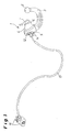
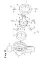
- FIG. 1 Trailer coupling 1 shown is attached via a one or more parts cross member to a vehicle (not shown).
- the hitch 1 includes in the embodiment a cranked, at its free end a coupling ball 2 supporting ball bar 3, which is arranged with its ball rod bearing head 4 here between a mounting flange 5 and an opposite with the interposition of a shim 6 connecting plate 7.
- the holder of the ball rod bearing head by means of a hollow shaft 8 and 108 (see Fig. 2 to 13 or 14) on which the ball rod is arranged with its ball rod bearing head.
- the ball rod can be closed at one end by end caps or sleeves and only a component, possibly including a gusset plate attached.
- a mounting bush which is inserted from the outside of the mounting flange 5 forth in a centered bore with respect to the hollow shaft with a hub, wherein the central bore of the outer side of the mounting flange 5 is overhanged by a flange of the mounting bush, so that through the flange 12 screwed into a collar of the hollow shaft mounting screws 14 provide for an exact positioning of the hollow shaft.
- the ball rod 3 is locked as rotatably as in their in Fig. 9 after rest in the other rotational end position shown rest position.
- a handwheel release mechanism 16 connected via a Bowden cable 17, at its in the ball rod bearing head 4 immersed end with a in the hollow shaft 8 and 108 movable back and forth locking pin 18 (see Fig. 13 and 14 ) connected is.
- the ball rod 3 via a Formschiusstress 19, which consists of balls 20 and these oppositely associated calotte 21, rotatably fixed.
- the swash bearing 23 in the FIGS. 2 to 10 shown ball bar 3 is in detail the FIG. 11 combined with FIG. 12 refer to.
- the ball head 22 of the swash bearing 23 is formed integrally with the hollow shaft 8 and arranged with the interposition of a bearing ring 27 in a half-shell-like housing of the ball bearing head 4.
- a path control 28 is provided, in the form of a link 29 in the ball head 22 as a circumferential radial groove 30 with on one ball half against the other ball half opposite direction of the Nutbahnen 31st a or 31 b (cf. FIG. 12 II and III) is incorporated.
- the path control 128 has the following means 133 or guide elements in the curved connecting plate 24, to which a set 129 with a funnel-shaped recess 129 is assigned in the spherical ball-and-socket bearing head 104.
- the receptacles 40 may be provided on their facing in the locking direction running surface with a run-on slope, which cause a selectively aligned force for axial displacement of the ball bar 3 and the ball rod bearing head 4 in the locking direction when tightening the ball bar 3 in the locked position in the rotary end positions.
- the locking pin 18, which is formed at its the balls 39 through the radial bores 37 and 38 in the receptacle 40 of the bearing ring 27 and 25 oppressive scope with a self-locking slope and / or an undercut is in this locked position by a force element in the form a compression spring 41 moves, which is arranged in the hollow shaft 8 and in the hollow shaft 108 with a chamber-like, passed through the curved connecting plate 24 extension.
- the open ends of the hollow shaft 8 and 108 are provided with an end cap 42 or the like, while at the other end 43, a Bautenzug or electrical actuation of the trigger mechanism can be connected.
- the locking pin 18 To trigger and thus unlock on the one hand the locking pin 18 and on the other hand, the I-ormschiusskonturen (balls 20 and dome 21) of the positive connection 19 between hollow ball 22 and ball rod bearing head 4 or spherical Kugelstangenlagerkopf 104 and curved in the exemplary embodiment connecting plate 24 and thus releasing the ball bar 3 for pivoting in a different rotational position, the locking pin 18 is reset by actuation of the attached in a trunk of the motor vehicle handwheel release mechanism 16 against the compression spring 41, which pretensions, reset.
- the locking means or balls 39 can thus fall from the receptacle 40 of the bearing ring 25 and 27 through the radial bores 37 and 38 of the ball head 22 and the hollow shaft 108 inwardly and put in front of the head of the locking pin 18. Simultaneously with this, the ball-rod bearing head 4 or 104 is automatically moved axially due to the weight of the ball rod 3 due to gravity, so that the form-locking connection 19 of the balls 20 and calottes 21 is released.
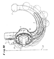
- FIGS. 2 to 9 are shown with respect to a schematically indicated vehicle rear plate 43 different phases of the targeted by the web control 28 sequence of movements during pivoting of the ball bar 3 and the ball bar bearing head 4, all of the angle data given below are only exemplary.
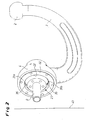
- FIG. 2 has the ball rod 3 in position with operating position after release for unlocking with axial displacement already lifted off the ball head 22. It is thus free to pivot in the rest position, the FIG. 3 the pivoting by 30 ° reproduces, with their reaching the guided in the Nutbahnen 31 a and 31 b of the radial groove 30 and 29 scenes pins 34 of the bolted to the ball bearing head 4 retaining ring 32 due to the web control 28, the tumbling motion of the ball rod 3 initiates.
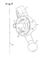
- FIG. 4 the ball rod 3 is pivoted by 60 ° and staggered by about 1.5 ° to the ball head 22 until they according to FIG. 5 at a 90 ° swivel angle and a tumbling angle of about 5 ° has reached the zenith and with the further pivoting of the ball bar 3, the wobble return movement takes place, wherein FIG. 6 at the pivoting of 120 ° shows a wobble angle of about 1.5 °, as comparable with FIG. 4 , With the in FIG. 7 shown pivoting distance of 150 ° - always based on the starting position - the web-controlled wobbling motion is completed, so that after a further pivoting of 30 ° and thus a total of 180 °, as in FIG. 8 shown, the position for locking or locking the ball rod 3 is present in the rest position of the trailer coupling.
- the distance occupied by the ball rod 3 with its cranked area in the critical section to the vehicle rear plate 43 remains approximately the same due to the tumbling motion.
- the web-controlled pivoting system with movements around a space-changing, possibly axially displaceable point can be made very narrow construction and thus takes up little space to complete.
Landscapes
- Engineering & Computer Science (AREA)
- Transportation (AREA)
- Mechanical Engineering (AREA)
- Pivots And Pivotal Connections (AREA)
- Vehicle Body Suspensions (AREA)
- Motor Or Generator Frames (AREA)
- Glass Compositions (AREA)
- Insulation, Fastening Of Motor, Generator Windings (AREA)
- Gear-Shifting Mechanisms (AREA)
- Medicines Containing Antibodies Or Antigens For Use As Internal Diagnostic Agents (AREA)
- Vehicle Waterproofing, Decoration, And Sanitation Devices (AREA)
Abstract
Description
Die Erfindung betrifft eine Anhängekupplung für Kraftfahrzeuge, umfassend eine fahrzeugfest angeordnete, über eine Bahnsteuerung schwenkbar sowie axial verschieblich gelagerte Kugelstange, die an ihrem freien Ende eine Kupplungskugel trägt und sowohl in ihrer Ruhelage als auch in ihrer Betriebslage über in Eingriff bringbare Formschlusskonturen einerseits eines Kugelstangenlagerkopfes und andererseits eines diesem gegenüberliegenden Bauteiles drehfest festlegbar ist.The invention relates to a towing hitch for motor vehicles, comprising a fixed vehicle, pivotally mounted via a path control and axially displaceable ball rod, which carries a coupling ball at its free end and both in its rest position and in its operating position via engageable form-fitting contours on the one hand a ball rod bearing head and on the other hand, a rotationally fixed this opposite component is fixable.
Eine Anhängekupplung mit einer die Dreh- Schwenkbewegung der Kugelstange bewirkenden Bahnsteuerung ist aus der
Bei einer durch die
Zum Festlegen und Freigeben dieser bekannten Kugelstange dient ein verstellbares, die Lagerhülse bzw den Kugelstangenlagerkopf abstützendes Widerlager, das wie der Kugelstangenlagerkopf auf einem Lagerbolzen angeordnet ist, der über einen Befestigungsansatz bzw. Anbauflansch an einem mit dem Fahrzeug verbundenen Querrohr befestigt ist. In der einen Axialstellung des die Lagerhülse abstützenden Widerlagers stehen die Formschlusskonturen von Lagerbolzen und Lagerhülse so miteinander in Eingriff, dass die Lagerhülse und damit die Kugelstange gegenüber dem Fahrzeug nicht verdreht werden kann. In der zweiten Axialstellung, in der das Widerlager dann von dem Befestigungsansatz entfernt ist, kann die Lagerhülse so weit abgerückt werden, dass die Formschlusskonturen außer Eingriff kommen, worauf die Lagerhülse samt daran angeordneter Kugelstange zwischen der Ruhe- und der Betriebslage verschwenkt werden kann. Die jeweilige Verriegelungsposition wird danach durch eine erneute Axialverschiebung des Widerlagers erreicht.For setting and releasing this known ball bar is an adjustable, the bearing sleeve or the ball rod bearing head abutment abutment, which is arranged as the ball rod bearing head on a bearing pin, which is attached via a mounting lug or mounting flange on a cross-tube connected to the vehicle. In one axial position of the bearing sleeve supporting abutment are the form-fitting contours of bearing pin and bearing sleeve so engaged that the bearing sleeve and thus the ball bar against the vehicle can not be rotated. In the second axial position, in which the abutment is then removed from the attachment lug, the bearing sleeve can be moved so far that the form-fitting contours are disengaged, whereupon the bearing sleeve together with ball bar arranged between the rest and the operating position can be pivoted. The respective locking position is then achieved by a renewed axial displacement of the abutment.
Weiterhin sind Anhängerkupplungen bekannt, die zum Festlegen und Freigeben der Kugelstange eine Verriegelung aufweisen, die einen gegen ein anstehendes Kraftelement, insbesondere eine Druckfeder, über ein von außen betätigbares Druck- oder Zugmittel zurückstellbaren Sperrbolzen besitzt, dem radial ein- und ausrückbare Rastmittel, insbesondere Kugeln, zugeordnet sind, wie aus der
Aus der
Eine durch die
Der Erfindung liegt die Aufgabe zugrunde, eine gattungsgemäße, weitestgehend wartungsfreie Anhängekupplung zu schaffen, die beim Verschwenken (motorisch oder von Hand) der Kugelstange beliebige und variable Schwenkbewegungen erlaubt, insbesondere um die Kugelstange mit geringstmöglichem Bewegungsraum in eine nicht sichtbare Außerbetriebsstellung verschwenken zu können; außerdem soll eine selbsttätige axiale Zwangsverschiebung der Kugelstange ermöglicht werden.The invention has for its object to provide a generic, largely maintenance-free towing hitch, which allows pivoting (motor or by hand) of the ball rod arbitrary and variable pivoting movements, in particular to pivot the ball bar with the least possible movement space in a non-visible inoperative position; In addition, an automatic axial displacement of the ball rod to be made possible.
Diese Aufgabe wird erfindungsgemäß dadurch gelöst, dass der Kugelstangenlagerkopf auf einem beim Schwenken der Kugelstange von der einen in die andere Endlage Bewegungen um einen sich im Raum verändernden Punkt bewirkendes Taumellager mit einer Bahnsteuerung des Kugelstangeniagerkopfes angeordnet ist und dass das Taumellager auf einer Hohlwelle angeordnet ist, die mit einer zentral integrierten axial wirkenden Verriegelung des Kugelstangenlagerkopfes zum in Eingriff bringen der Formschlußkonturen sowohl in der Betriebslage als auch in der Ruhelage der Kugelstange ausgebildet ist. Es läßt sich damit erreichen, dass die Schwenkbewegungen nicht mehr von Drehachsen, wie im Raum schräg verlaufenden Drehachsen, abhängig sind. Nach dem manuell oder motorisch bewirkten axialen Abrücken der Kugelstange, wozu nur ein geringer axialer Verschiebeweg benötigt wird, um die Formschlusskonturen außer Eingriff zu bringen, kann die Kugelstange mit einer fast linearen Bewegung, d.h. weitestgehend in jeder Position den gleichen Abstand zum Fahrzeugheck bzw. Fahrzeugheckblech einhaltend von Hand oder motorisch in ihre Endlage verschwenken und dort anschließend wieder verriegelt werden. Das Taumellager ist erfindungsgemäß auf einer Hohlwelle angeordnet, die zentral integriert mit einer axial wirkenden Verriegelung des Kugelstangenlagerkopfes zum in Eingriff bringen der Formschlusskonturen sowohl in der Betriebslage als auch in der Ruhelage der Kugelstange ausgebildet ist. Durch die Abkehr von einer auf einem Lagerbolzen bzw. einer durchgängigen Lagerachse gelagerten Kugelstange, die vielmehr auf der Hohlwelle mit zentral integrierter Verriegelung angeordnet ist, lässt sich ein in sich geschlossenes, weitestgehend wartungsfreies System erreichen. Die axial wirkende Verriegelung ermöglicht zudem eine gleichzeitig selbsttätige axiale Zwangsverschiebung der Kugelstange, sobald die Sperrung bzw. Verriegelung in einer Drehendlage aufgehoben wird.This object is achieved in that the ball rod bearing head is arranged on a pivoting of the ball rod from the one to the other end position movements about a changing point in space causing swash bearing with a path control of Kugelstangeniagerkopfes and that the swash bearing is arranged on a hollow shaft, which is formed with a centrally integrated axially acting locking of the ball rod bearing head for engaging the positive locking contours both in the operating position and in the rest position of the ball rod. It can thus be achieved that the pivoting movements are no longer dependent on axes of rotation, as in space oblique axes of rotation. After the axial or axial axial displacement of the ball bar, which requires only a small amount of axial displacement to disengage the positive locking contours, the ball bar can be moved with an almost linear movement, i. largely in each position the same distance to the rear of the vehicle or rear end sheet metal swing by hand or motor to pivot into its final position and then be locked again. The swash bearing is inventively arranged on a hollow shaft, which is formed centrally integrated with an axially acting locking of the ball rod bearing head for engaging the positive locking contours both in the operating position and in the rest position of the ball rod. By turning away from a bearing rod mounted on a bearing pin or a continuous bearing rod ball rod, which is rather arranged on the hollow shaft with centrally integrated locking, can be achieved in a self-contained, largely maintenance-free system. The axially acting lock also allows a simultaneous automatic forced displacement of the ball bar, as soon as the blocking or locking is released in a rotary end position.
Eine Ausführung der Erfindung sieht vor, dass das Taumellager einen Kugelkopf aufweist, der unter Zwischenschaltung eines Lagerringes in einem halbschalenartigen Gehäuse des Kugelstangenlagerkopfes angeordnet ist. Nach dem Auslösen der Verriegelung bzw. Formschlussverbindung und dem damit einhergehenden axialen Abrücken bzw. Verschieben des Kugelstangenlagerkopfes kann sich dieser mit von der Bahnsteuerung vorgegebenem, optimiertem Bewegungsverlauf auf dem Kugelkopf verschwenken.An embodiment of the invention provides that the swash bearing has a ball head, the interposition of a bearing ring in a half-shell-like Housing of the ball rod bearing head is arranged. After triggering the locking or form-locking connection and the concomitant axial displacement or displacement of the ball-rod bearing head, this can pivot with the path control predetermined, optimized movement pattern on the ball head.
Bei einer anderen Ausführung weist das Taumellager einen sphärisch ausgebildeten Lagerring auf, der - optional über einen komplementär sphärischen Zwischenring - den Kugelstangenlagerkopf trägt. Die sich hier um den Lagerring drehende Kugelstange kann große Taumelwinkel durchführen.In another embodiment, the swash bearing has a spherical bearing ring which - optionally via a complementary spherical intermediate ring - carries the ball rod bearing head. The ball bar rotating around the bearing ring here can perform large wobble angles.
Hierbei lässt sich nach einer vorteilhaften Ausgestaltung der Kugeistangenlagerkopf kugelig ausbilden und in einem gewölbtem Bauteil, z. B. ein topfartiges Drehteil oder ein Verbindungsblech, anordnen. Ein zur Befestigung an einem Grundträger des Fahrzeugs benötigtes Verbindungsblech kann somit schon gleich auch den Kugelstangenlagerkopf aufnehmen, wobei die Formschlusskonturen, z. B. Kugeln und Kalotten oder Verzahnung und Gegenverzahnung, einerseits im Kugelstangenlagerkopf und andererseits in der Wölbung des Bauteils bzw. insbesondere Verbindungsbleches vorgesehen sind.In this case, according to an advantageous embodiment of the Kugeistangenlagerkopf spherical form and in a curved component, for. B. a pot-like rotary part or a connecting plate, arrange. A required for attachment to a base support of the vehicle connection plate can thus already take up the same ball bearing head, wherein the positive locking contours, z. B. balls and calottes or teeth and counter teeth, on the one hand in the ball rod bearing head and on the other hand in the curvature of the component or in particular connecting plate are provided.
Ausgestaltungen der Erfindung sehen vor, dass die Hohlwelle in dem Verbindungsblech angeordnet ist oder sich bis in den Kugelkopf fortsetzend einstückig mit diesem ausgebildet ist. Im letztgenannten Fall liegt sozusagen ein Hohlkugelbolzen vor.Embodiments of the invention provide that the hollow shaft is arranged in the connecting plate or is integrally formed with this up to the ball head continuing. In the latter case, so to speak, there is a hollow ball pin.
In bevorzugter Ausführung umfasst die Verriegelung einen in der Hohlwelle geführten, gegen ein anstehendes Kraftelement über ein von außen betätigbares Druck- oder Zugmittel zurückstellbaren Sperrbolzen und mit diesem zusammenwirkende, in Radialbohrungen der Hohlwelle angeordnete, ein und ausrückbare Rastmittel. In der Verriegelungsposition, die durch eine selbsthemmende Schräge und/oder einen Hinterschnitt des Sperrbolzens zusätzlich gesichert werden kann, drückt der Sperrbolzen die Rastmittel, z. B. Kugeln, Stifte oder dergleichen, in den Radialbohrungen nach außen in den Lagerring und verhindert damit eine axiale Verstellung der Kugelstange. Wenn dann das Kraftelement, z. B. eine Druckfeder, vorgespannt bzw. zusammengezogen wird, beispielsweise mittels eines Handrades, wie aus der bereits genannten
Zum taumelnden, raum- und platzsparenden Verschwenken der Kugelstange in ihre Drehendlagen wird erfindungsgemäß vorgeschlagen, dass die Bahnsteuerung als Kulisse mit darin eingreifenden Folgemitteln ausgebildet ist. Alternativ zu einer Bahnsteuerung mit ineinandergreifenden Teilen, wie eine Kulisse und Folgemittel (Stift, Bolzen oder dergleichen), können auch aufeinander gleitende bzw. abgleitende Bauteile vorgesehen werden.For tumbling, space- and space-saving pivoting of the ball rod in its rotational end positions is proposed according to the invention that the web control is designed as a backdrop with engaging thereon followers. As an alternative to a path control with interlocking parts, such as a slide and following means (pin, bolt or the like), also sliding or sliding components can be provided on each other.
Hierbei empfiehlt es sich, dass die Kulisse als Radialnut im Kugelkopf mit auf der einen Kugelkopfhälfte zu der anderen Kugelkopfhälfte entgegengerichtetem Verlauf der Nutbahnen ausgebildet ist und die Folgemittel zueinander diametral in einem im Kugelstangenlagerkopf vorgesehenen Haltering angeordnete Stifte sind. Die Nutbahnen geben der Kugelstange uber die eingreifenden Stifte oder dergleichen Führungselemente bzw. Folgemittel sowohl den Schwenkverlauf bzw das Taumeln um den Hohlkugelbolzen bzw. den sphärischen Lagerring als auch das Ab- und Einrücken, d.h. den axialen Verschiebeweg um wenige Millimeter, exakt vor.Here, it is recommended that the backdrop is formed as a radial groove in the ball head with on one ball half to the other ball half opposite direction course of the Nutbahnen and the following means are diametrically opposed to each other in a ball rod bearing head provided in the retaining ring arranged pins. The Nutbahnen give the ball bar on the engaging pins or the like guide elements or followers both the pivoting or tumbling around the hollow ball and the spherical bearing ring and the engagement and disengagement, i. the axial displacement by a few millimeters, exactly before.
Wenn den Folgemitteln in den Taumel-Endlagen des Kugelstangenlagerkopfes im Kugelkopf axiale Ausnehmungen zugeordnet sind, in die die Nutbahnen übergehen, können in den Drehendlagen die Stifte bzw. Folgemittel lagesicher in die Ausnehmungen eintauchen. Dieses Eintauchen in die Ausnehmungen wird erleichtert, wenn der Übergang von den Nutbahnen zu den Ausnehmungen trichterförmig ausgebildet ist.If the followers in the wobble end positions of the ball rod bearing head in the ball head axial recesses are assigned, in which pass over the Nutbahnen, can dive into the recesses in the Drehendlagen the pins or follower. This immersion in the recesses is facilitated if the transition from the Nutbahnen to the recesses is funnel-shaped.
Weitere Merkmale und Einzelheiten der Erfindung ergeben sich aus den Ansprüchen und der nachfolgenden Beschreibung von in den Zeichnungen dargestellten Ausführungsbeispielen der Erfindung. Es zeigen:
- Fig. 1
- in einer perspektivischen Gesamtansicht eine Anhängekupplung mit in ihrer Betriebslage verriegelter, sich mittig in Längsrichtung eines nicht dargestellten Fahrzeugs erstreckender Kugelstange, hier angeschlossen an einen Handrad-Auslösemechanismus;
- Fig. 2
- als Einzelheit die nach dem Auslösen axial bereits verschobene Kugelstange;
- Fig. 3
- die Kugelstange nach
Fig. 2 um 30° geschwenkt und zusammenfallend mit der Einleitung der Taumelbewegung; - Fig. 4
- die Kugelstange nach
Fig. 2 um 60° geschwenkt und um ca. 1,5° getaumelt; - Fig. 5
- die Kugelstange nach
Fig. 2 um 90° geschwenkt und ca. 5° getaumelt, - Fig. 6
- die Kugelstange nach
Fig. 2 um 120° geschwenkt in der TaumelRückbewegung, getaumelt ca. um 1,5°; - Fig. 7
- die Kugelstange nach
Fig. 7 um 150° geschwenkt und am Ende der Taumelbewegung; - Fig. 8
- die Kugelstange nach
Fig. 2 um 180° geschwenkt vor dem Einleiten des Einrast- bzw. Verriegelungsvorgangs in der Ruhestellung; - Fig. 9
- die Kugelstange nach
Fig. 2 in der axial eingerückten, verrasteten Ruhestellung; - Fig.10
- eine Bewegungsübersicht mit einzelnen Phasen der Kugelstange auf dem Weg aus ihrer Betriebsstellung in die Ruhestellung;
- Fig.11
- die Kugelstange nach
Fig. 2 einschließlich Taumellagerung in Explosionsdarstellung mit Ansicht in Fahrtrichtung von vorne gesehen; - Fig.12
- als Einzelheit der Kugelstange nach
Fig. 2 in mehreren Ansichten einen Hohlkugelbolzen der Taumellagerung; - Fig.13
- die Kugelstange nach
Fig. 2 in einem Längsschnitt durch deren auf einer Taumellagerung angeordnetem Kugelstangenlagerkopf; und - Fig.14
- in einem schematischen Längsschnitt eine andere Ausführung einer Taumellagerung der Kugelstange.
- Fig. 1
- in a perspective overall view of a hitch with locked in their operating position, extending centrally in the longitudinal direction of a vehicle, not shown extending ball bar, here connected to a handwheel release mechanism;
- Fig. 2
- as a detail, after the release already axially displaced ball bar;
- Fig. 3
- the ball bar
Fig. 2 pivoted by 30 ° and coinciding with the initiation of the tumbling motion; - Fig. 4
- the ball bar
Fig. 2 swiveled by 60 ° and staggered by approx. 1.5 °; - Fig. 5
- the ball bar
Fig. 2 swiveled by 90 ° and tumbled about 5 °, - Fig. 6
- the ball bar
Fig. 2 pivoted by 120 ° in the TaumelRückbewegung, staggered about 1.5 °; - Fig. 7
- the ball bar
Fig. 7 pivoted by 150 ° and at the end of the tumbling motion; - Fig. 8
- the ball bar
Fig. 2 pivoted by 180 ° before the initiation of the latching or locking operation in the rest position; - Fig. 9
- the ball bar
Fig. 2 in the axially engaged, latched rest position; - Figure 10
- a movement overview with individual phases of the ball rod on the way from its operating position to the rest position;
- Figure 11
- the ball bar
Fig. 2 including swash bearing in exploded view with view in the direction of travel seen from the front; - Figure 12
- as a detail of the ball bar
Fig. 2 in several views a hollow ball pin of the swash bearing; - Figure 13
- the ball bar
Fig. 2 in a longitudinal section through their arranged on a swash bearing ball rod bearing head; and - Figure 14
- in a schematic longitudinal section, another embodiment of a swash bearing of the ball rod.
Eine in
In der in
In den Drehendlagen (Betriebs- oder Ruhelage) ist die Kugelstange 3 über eine Formschiussverbindung 19, die hier aus Kugeln 20 und diesen gegenuberliegend zugeordneten Kalotten 21 besteht, drehfest festgelegt. Im Ausführungsbeispiel nach
Das Taumellager 23 der in den
Zur Verriegelung der Drehendlagen sind für den Sperrbolzen 18 in Radialbohrungen 37 des Kugelkopfes 22 (vgl. die
Der Sperrbolzen 18, der an seinem die Kugeln 39 durch die Radialbohrungen 37 bzw. 38 in die Aufnahme 40 des Lagerringes 27 bzw. 25 drückenden Umfang mit einer selbsthemmenden Schräge und/oder einem Hinterschnitt ausgebildet ist, wird in diese Sperrlage durch ein Kraftelement in Form einer Druckfeder 41 bewegt, die in der Hohlwelle 8 bzw. in der Hohlwelle 108 mit einer kammerartigen, durch das gewölbte Verbindungsblech 24 hindurchgeführten Verlängerung angeordnet ist. Die offenen Enden der Hohlwelle 8 bzw. 108 sind mit einer Endkappe 42 oder dergleichen verschlossen, während am anderen Ende 43 ein Bautenzug oder eine elektrische Betätigung des Auslösemechanismus angeschlossen werden kann.The locking
Zur Auslösung und damit Entriegeln einerseits des Sperrbolzens 18 und andererseits der I-ormschiusskonturen (Kugeln 20 und Kalotten 21) der Formschlußverbindung 19 zwischen Hohlkugel 22 und Kugelstangenlagerkopf 4 bzw. kugeligem Kugelstangenlagerkopf 104 und im Ausführungsbeispiel gewölbtem Verbindungsblech 24 und damit Freigeben der Kugelstange 3 zum Verschwenken in eine andere Drehlage, wird der Sperrbolzen 18 durch Betätigung des in einem Kofferraum des Kraftfahrzeugs befestigten Handrad-Auslösemechanismus 16 gegen die Druckfeder 41, die sich dabei vorspannt, zurückgestellt. Die Rastmittel bzw. Kugeln 39 können damit aus der Aufnahme 40 des Lagerrings 25 bzw. 27 durch die Radialbohrungen 37 bzw. 38 des Kugelkopfes 22 bzw. der Hohlwelle 108 nach innen fallen und sich vor den Kopf des Sperrbolzens 18 legen. Damit gleichzeitig einhergehend wird der Kugelstangenlagerkopf 4 bzw. 104 aufgrund des Gewichts der Kugelstange 3 schwerkraftbedingt selbsttätig axial wegbewegt, so dass die Formschlussverbindung 19 der Kugeln 20 und Kalotten 21 aufgehoben wird. Erst wenn die Kugelstange 3 hand- oder motorbetätigt in die Drehendlage verschwenkt und der Sperrbolzen 18 durch die Druckfeder 41 beaufschlagt in seine Verriegelungsposition wieder nach vorne bewegt worden ist, werden die Rastkugeln 39 wieder durch die Radialbohrungen 37 bzw. 38 in die Aufnahme 40 des Lagerringes 25 bzw. 27 gedrückt. Die Anhängekupplung ist damit wieder verriegelt.To trigger and thus unlock on the one hand the locking
In den
Nach
In der Ruhestellung nach
Der gesamte Schwenkverlauf der Kugelstange 3 aus der Betriebsstellung nach
Claims (11)
- A trailer coupling (1) for motor vehicles, comprising a ball neck (3) which is disposed fixedly on a vehicle, which is pivotable by means of a path control (28; 128) and which is mounted axially displaceably, which ball neck (3) has a coupling ball (2) at its free end and which can be fixed in a torque-proof manner both in its rest position and in its operating position by means of positive contours on the one hand of a ball neck bearing head (4; 104) and on the other hand of a component opposite thereto, which can be brought into engagement, characterised in that the ball neck bearing head (4; 104) is disposed on a tumble bearing (23; 123) effecting movements about a spatially varying point when the ball neck (3) pivots from the one end position to the other, with a path control (28; 128) of the ball neck bearing head (4; 104) and that the tumble bearing (23; 123) is disposed on a hollow shaft (8; 108) which is configured with a centrally integrated, axially acting locking of the ball neck bearing head (4; 104) for bringing into engagement the positive contours (19; 20, 21) both in the operating position and in the rest position of the ball neck (3).
- The trailer coupling according to claim 1, characterised in that the tumble bearing (23) has a ball head (22) which is disposed in a semi-monocoque-type housing of the ball neck bearing head (4; 104) with an interposed bearing ring (27).
- The trailer coupling according to claim 1, characterised in that the tumble bearing (123) has a spherically configured bearing ring (25) which bears the ball neck bearing head (4; 104), preferably by means of a complementary spherical intermediate ring (26).
- The trailer coupling according to claim 3, characterised in that the ball neck bearing head (104) is configured to be spherical and is disposed in a curved attachment part (24).
- The trailer coupling according to claim 3 or 4, characterised in that the hollow shaft (108) is disposed in the attachment part (24).
- The trailer coupling according to claim 2, characterised in that the hollow shaft (8) is configured to extend into the ball head (22) in one piece with said ball head.
- The trailer coupling according to any one of claims 1 to 6, characterised in that the lock comprises a locking bolt (18) which is guided in the hollow shaft (8; 108) and which can be set back against an in-situ force element (41) by means of an externally actuatable pressure or tension means (16) and insertable and extendable latching means (39) cooperating with said locking bolt, disposed in radial holes (37; 38) of the hollow shaft (108; 8).
- The trailer coupling according to any one of claims 1 to 7, characterised in that the path control (28; 138) is configured as a link (29; 129) with following means (33; 133) engaging therein.
- The trailer coupling according to claim 8, characterised in that the link (29) is configured as a radial groove (30) in the ball head (22) with the course of the groove tracks (31a; 31b) oppositely directed on one ball head half to the other ball head half and the following means (33) are pins (34) disposed diametrically to one another in a retaining ring (32) provided in the ball neck bearing head (4).
- The trailer coupling according to claim 8 or 9, characterised in that axial recesses (35) into which the groove tracks (31a; 31b) go over are assigned to the following means (33; 34) in the tumble end positions of the ball neck bearing head (4) in the ball head (22).
- The trailer coupling according to claim 10, characterised in that the transition from the groove tracks (31a; 31b) to the recesses (35) is configured to be funnel-shaped.
Priority Applications (1)
| Application Number | Priority Date | Filing Date | Title |
|---|---|---|---|
| EP09160049A EP2088008B8 (en) | 2003-11-21 | 2004-10-05 | Trailer hitch for vehicles |
Applications Claiming Priority (2)
| Application Number | Priority Date | Filing Date | Title |
|---|---|---|---|
| DE10354753 | 2003-11-21 | ||
| DE10354753.3A DE10354753B4 (en) | 2003-11-21 | 2003-11-21 | Towing hitch for motor vehicles |
Related Child Applications (1)
| Application Number | Title | Priority Date | Filing Date |
|---|---|---|---|
| EP09160049A Division EP2088008B8 (en) | 2003-11-21 | 2004-10-05 | Trailer hitch for vehicles |
Publications (2)
| Publication Number | Publication Date |
|---|---|
| EP1533149A1 EP1533149A1 (en) | 2005-05-25 |
| EP1533149B1 true EP1533149B1 (en) | 2010-01-20 |
Family
ID=34428872
Family Applications (2)
| Application Number | Title | Priority Date | Filing Date |
|---|---|---|---|
| EP09160049A Active EP2088008B8 (en) | 2003-11-21 | 2004-10-05 | Trailer hitch for vehicles |
| EP04023640A Active EP1533149B1 (en) | 2003-11-21 | 2004-10-05 | Trailer hitch for vehicles |
Family Applications Before (1)
| Application Number | Title | Priority Date | Filing Date |
|---|---|---|---|
| EP09160049A Active EP2088008B8 (en) | 2003-11-21 | 2004-10-05 | Trailer hitch for vehicles |
Country Status (3)
| Country | Link |
|---|---|
| EP (2) | EP2088008B8 (en) |
| AT (2) | ATE455662T1 (en) |
| DE (3) | DE10354753B4 (en) |
Cited By (6)
| Publication number | Priority date | Publication date | Assignee | Title |
|---|---|---|---|---|
| EP2412550A1 (en) | 2010-07-31 | 2012-02-01 | WESTFALIA - Automotive GmbH | Tow bar |
| DE102010032991A1 (en) | 2010-07-31 | 2012-02-02 | Westfalia-Automotive Gmbh | Trailer coupling for motor vehicle, has bearing, which has vehicle bearing part and coupling arm-bearing part that is mounted at vehicle bearing part between custom position and non-usage position |
| EP2692554A1 (en) | 2012-08-03 | 2014-02-05 | WESTFALIA - Automotive GmbH | Tow bar coupling with a locking device |
| DE102013012303A1 (en) | 2012-08-03 | 2014-02-06 | Westfalia-Automotive Gmbh | Plug-type trailer coupling for motor vehicle e.g. passenger car, has adjusting unit that is provided for adjusting actuating element to compensate wear on actuating surface, in unworn portion of actuating surface |
| DE102014221742A1 (en) * | 2014-10-27 | 2016-04-28 | Zf Friedrichshafen Ag | Swivel module of a trailer hitch |
| EP1557300B2 (en) † | 2004-01-22 | 2021-11-10 | ACPS Automotive GmbH | Trailer hitch |
Families Citing this family (28)
| Publication number | Priority date | Publication date | Assignee | Title |
|---|---|---|---|---|
| DE102004004501B4 (en) † | 2004-01-22 | 2021-07-01 | ACPS Automotive GmbH | Trailer coupling |
| EP1634730A1 (en) * | 2004-09-14 | 2006-03-15 | MVG Metallverarbeitungsgesellschaft mbH | Trailer coupling with ball joint |
| DE102005032474A1 (en) * | 2005-07-07 | 2007-01-11 | Oris Fahrzeugteile Hans Riehle Gmbh | hitch |
| DE102005036185B4 (en) * | 2005-08-02 | 2018-12-13 | Volkswagen Ag | actuator |
| DE102005047379A1 (en) * | 2005-09-28 | 2007-04-12 | Scambia Industrial Developments Aktiengesellschaft | Draw bar for motor vehicle, has movable adjusting body provided at coupling carrier for causing relative movement of positive lock structures, where relative movement of positive locking structures takes place transverse to rotational axis |
| DE102006035261A1 (en) | 2006-07-29 | 2008-01-31 | Scambia Industrial Developments Aktiengesellschaft | Trailer coupling for vehicle, has rotating block device with rotating block body, which is movable in guidance direction with component in radial direction to swiveling axis and drive is actuator |
| DE102006051096B4 (en) | 2006-10-25 | 2013-09-12 | Mvg Metallverarbeitungsgesellschaft Mbh | hitch |
| US8136803B2 (en) | 2007-01-15 | 2012-03-20 | Phd, Inc. | Armover clamp assembly |
| DE102007029051A1 (en) | 2007-06-21 | 2009-01-02 | Westfalia-Automotive Gmbh | Towing hitch for motor vehicles |
| DE102008018739A1 (en) * | 2008-04-14 | 2009-10-15 | Trw Automotive Gmbh | Vehicle-side coupling assembly of a trailer hitch |
| DE102008018738B4 (en) * | 2008-04-14 | 2020-12-17 | THK RHYTHM AUTOMOTIVE GmbH | On-vehicle coupling assembly of a trailer coupling |
| DE102008047547B4 (en) | 2008-09-16 | 2014-04-03 | Westfalia-Automotive Gmbh | Towing hitch for motor vehicles |
| DE102008043318A1 (en) | 2008-10-30 | 2010-05-12 | Mvg Metallverarbeitungsgesellschaft Mbh | Towing |
| DE102009045275B4 (en) * | 2009-10-02 | 2014-01-09 | Zf Friedrichshafen Ag | Swivel module for a trailer hitch |
| DE102009046931A1 (en) * | 2009-11-20 | 2011-05-26 | Zf Friedrichshafen Ag | Ball swivel module |
| DE102011078007A1 (en) * | 2011-06-22 | 2012-12-27 | Zf Friedrichshafen Ag | Tow-bar for towing trailer in towing vehicle, has ball neck for carrying coupling ball, and swiveling module is provided with two module parts, where latter part is moved relative to former part, and is connected with ball neck |
| DE102012008124A1 (en) † | 2012-04-25 | 2013-10-31 | Westfalia-Automotive Gmbh | Coupling arrangement for a rear carrier |
| DE102013100780A1 (en) * | 2013-01-25 | 2014-07-31 | Scambia Holdings Cyprus Limited | Towing hitch and load carrier device for a trailer hitch |
| DE102014005881A1 (en) | 2013-04-21 | 2014-10-23 | Westfalia-Automotive Gmbh & Co. Kg | Towing |
| DE102013007117A1 (en) | 2013-04-21 | 2014-10-23 | Westfalia-Automotive Gmbh | Towing |
| DE102013007115A1 (en) | 2013-04-21 | 2014-10-23 | Westfalia-Automotive Gmbh | Towing |
| EP2796303B1 (en) | 2013-04-21 | 2018-05-02 | WESTFALIA - Automotive GmbH | Trailer coupling |
| DE102013007111A1 (en) | 2013-04-21 | 2014-10-23 | Westfalia-Automotive Gmbh | Towing |
| DE102013007123A1 (en) | 2013-04-21 | 2014-10-23 | Westfalia-Automotive Gmbh | Towing |
| DE102013007122A1 (en) | 2013-04-21 | 2014-10-23 | Westfalia-Automotive Gmbh | Towing |
| DE102013007114A1 (en) | 2013-04-21 | 2014-10-23 | Westfalia-Automotive Gmbh | Towing |
| US11577561B2 (en) | 2017-12-20 | 2023-02-14 | Horizon Global (South Africa) (Pty) Ltd | Towbar with a hitch ball system |
| CN109094307B (en) * | 2018-07-25 | 2020-06-26 | 北京汽车股份有限公司 | Tow hook and car |
Family Cites Families (13)
| Publication number | Priority date | Publication date | Assignee | Title |
|---|---|---|---|---|
| US2910310A (en) * | 1957-12-06 | 1959-10-27 | Rudolph A Mulac | Ball and socket swivel for an electric light receptacle |
| US4225260A (en) * | 1979-03-02 | 1980-09-30 | Gulf & Western Manufacturing Company | Tie rod ball joint construction |
| DE9408478U1 (en) * | 1994-05-21 | 1994-09-08 | Westfalia Werke Knoebel | Rotary lock for a handwheel drive of linearly guided lifting racks |
| DE19654867C2 (en) * | 1995-09-13 | 1998-01-22 | Cartron Fahrzeugteile Gmbh | Swiveling trailer hitch for motor vehicles |
| DE19612959A1 (en) * | 1996-04-01 | 1997-10-02 | Oris Fahrzeugteile Riehle H | Trailer coupling |
| DE19711535C2 (en) * | 1997-03-20 | 2003-07-17 | Jaeger Cartronix Gmbh | Motorized trailer hitch for motor vehicles |
| DE19848487A1 (en) * | 1998-10-21 | 2000-05-04 | Oris Fahrzeugteile Riehle H | Trailer coupling |
| DE19859961C2 (en) * | 1998-12-29 | 2003-07-03 | Westfalia Automotive Gmbh & Co | Towbar with a swiveling ball neck |
| DE19944264A1 (en) | 1999-09-15 | 2001-03-22 | Jaeger Cartronix Gmbh | Trailer coupling with axial travel |
| EP1090782A3 (en) * | 1999-10-04 | 2002-02-06 | PEKA-Fahrzeugbau GmbH & Co. KG | Trailer hitch for motor vehicles |
| DE10032002A1 (en) * | 2000-06-30 | 2002-01-24 | Oris Fahrzeugteile Riehle H | Automobile towbar assembly has a moving locking body which moves between two positions to block and release the operating mechanism in a simple and secure system to hold and uncouple the trailer |
| DE10160990B4 (en) * | 2001-12-10 | 2007-11-08 | Hqm Sachsenring Gmbh | Joint with joint bearing sleeve |
| DE50302195D1 (en) * | 2002-02-28 | 2006-04-06 | Kober Ag | TILTABLE TOWING DEVICE FOR TOWING VEHICLES |
-
2003
- 2003-11-21 DE DE10354753.3A patent/DE10354753B4/en not_active Expired - Lifetime
-
2004
- 2004-10-05 AT AT04023640T patent/ATE455662T1/en not_active IP Right Cessation
- 2004-10-05 EP EP09160049A patent/EP2088008B8/en active Active
- 2004-10-05 EP EP04023640A patent/EP1533149B1/en active Active
- 2004-10-05 AT AT09160049T patent/ATE465898T1/en not_active IP Right Cessation
- 2004-10-05 DE DE502004011113T patent/DE502004011113D1/en active Active
- 2004-10-05 DE DE502004010669T patent/DE502004010669D1/en active Active
Cited By (6)
| Publication number | Priority date | Publication date | Assignee | Title |
|---|---|---|---|---|
| EP1557300B2 (en) † | 2004-01-22 | 2021-11-10 | ACPS Automotive GmbH | Trailer hitch |
| EP2412550A1 (en) | 2010-07-31 | 2012-02-01 | WESTFALIA - Automotive GmbH | Tow bar |
| DE102010032991A1 (en) | 2010-07-31 | 2012-02-02 | Westfalia-Automotive Gmbh | Trailer coupling for motor vehicle, has bearing, which has vehicle bearing part and coupling arm-bearing part that is mounted at vehicle bearing part between custom position and non-usage position |
| EP2692554A1 (en) | 2012-08-03 | 2014-02-05 | WESTFALIA - Automotive GmbH | Tow bar coupling with a locking device |
| DE102013012303A1 (en) | 2012-08-03 | 2014-02-06 | Westfalia-Automotive Gmbh | Plug-type trailer coupling for motor vehicle e.g. passenger car, has adjusting unit that is provided for adjusting actuating element to compensate wear on actuating surface, in unworn portion of actuating surface |
| DE102014221742A1 (en) * | 2014-10-27 | 2016-04-28 | Zf Friedrichshafen Ag | Swivel module of a trailer hitch |
Also Published As
| Publication number | Publication date |
|---|---|
| DE502004011113D1 (en) | 2010-06-10 |
| EP2088008A1 (en) | 2009-08-12 |
| DE502004010669D1 (en) | 2010-03-11 |
| EP1533149A1 (en) | 2005-05-25 |
| ATE465898T1 (en) | 2010-05-15 |
| EP2088008B8 (en) | 2010-06-16 |
| EP2088008B1 (en) | 2010-04-28 |
| ATE455662T1 (en) | 2010-02-15 |
| DE10354753B4 (en) | 2014-07-24 |
| DE10354753A1 (en) | 2005-06-30 |
Similar Documents
| Publication | Publication Date | Title |
|---|---|---|
| EP1533149B1 (en) | Trailer hitch for vehicles | |
| EP1504928B1 (en) | Trailer hitch | |
| EP1637364B1 (en) | Trailer coupling | |
| EP0850147B1 (en) | Motor vehicle trailer coupling | |
| DE3827564C2 (en) | Locking device for vehicles | |
| EP2017097B1 (en) | Towbar for motor vehicles | |
| EP1475253A1 (en) | Trailer coupling for motor vehicles | |
| DE10252722B3 (en) | Trailer coupling for motor vehicles has tow bar bearing head with centrally integrated locking mechanism, located on hollow shaft fastened to mounted flange | |
| DE19826618C2 (en) | Towing | |
| DE202006011346U1 (en) | Pivoting hitch for towing vehicles | |
| EP2711207A2 (en) | Spherical swivel module | |
| EP1561610B1 (en) | Trailer hitch mechanism | |
| WO2016162317A1 (en) | Hood hinge having a rotatable release mechanism | |
| EP2711210A2 (en) | Spherical swivel module | |
| EP1407901B1 (en) | Towing hitch for towing vehicles | |
| EP1634730A1 (en) | Trailer coupling with ball joint | |
| EP1614556B1 (en) | Trailer coupling for motor vehicles | |
| DE102006051096B4 (en) | hitch | |
| EP2181868B1 (en) | Tow bar | |
| DE102012025459A1 (en) | Towing device for vehicle, has link controller with twin stops for movement of ball neck for non-use position and use position, and is provided with curved track which is designed continuously | |
| EP2671739A2 (en) | Actuation system for a trailer coupling of a motor vehicle | |
| DE10347816B4 (en) | Trailer coupling with load-free pivot bearing device | |
| DE20215508U1 (en) | Towing device for towing vehicles comprises a tow bar movably mounted about two axes of rotation, and a mechanical drive having a mechanism for generating a superimposed movement of the tow bar about both axes | |
| DE102014212598B4 (en) | Adjustable vehicle seat | |
| DE10340347B4 (en) | Trailer coupling for motor vehicles |
Legal Events
| Date | Code | Title | Description |
|---|---|---|---|
| PUAI | Public reference made under article 153(3) epc to a published international application that has entered the european phase |
Free format text: ORIGINAL CODE: 0009012 |
|
| AK | Designated contracting states |
Kind code of ref document: A1 Designated state(s): AT BE BG CH CY CZ DE DK EE ES FI FR GB GR HU IE IT LI LU MC NL PL PT RO SE SI SK TR |
|
| AX | Request for extension of the european patent |
Extension state: AL HR LT LV MK |
|
| 17P | Request for examination filed |
Effective date: 20051025 |
|
| AKX | Designation fees paid |
Designated state(s): AT BE BG CH CY CZ DE DK EE ES FI FR GB GR HU IE IT LI LU MC NL PL PT RO SE SI SK TR |
|
| 17Q | First examination report despatched |
Effective date: 20060717 |
|
| RAP1 | Party data changed (applicant data changed or rights of an application transferred) |
Owner name: WESTFALIA - AUTOMOTIVE GMBH |
|
| GRAP | Despatch of communication of intention to grant a patent |
Free format text: ORIGINAL CODE: EPIDOSNIGR1 |
|
| RTI1 | Title (correction) |
Free format text: TRAILER HITCH FOR VEHICLES |
|
| GRAS | Grant fee paid |
Free format text: ORIGINAL CODE: EPIDOSNIGR3 |
|
| GRAA | (expected) grant |
Free format text: ORIGINAL CODE: 0009210 |
|
| AK | Designated contracting states |
Kind code of ref document: B1 Designated state(s): AT BE BG CH CY CZ DE DK EE ES FI FR GB GR HU IE IT LI LU MC NL PL PT RO SE SI SK TR |
|
| REG | Reference to a national code |
Ref country code: GB Ref legal event code: FG4D Free format text: NOT ENGLISH |
|
| REG | Reference to a national code |
Ref country code: CH Ref legal event code: EP |
|
| REG | Reference to a national code |
Ref country code: IE Ref legal event code: FG4D |
|
| REF | Corresponds to: |
Ref document number: 502004010669 Country of ref document: DE Date of ref document: 20100311 Kind code of ref document: P |
|
| REG | Reference to a national code |
Ref country code: NL Ref legal event code: VDEP Effective date: 20100120 |
|
| PG25 | Lapsed in a contracting state [announced via postgrant information from national office to epo] |
Ref country code: ES Free format text: LAPSE BECAUSE OF FAILURE TO SUBMIT A TRANSLATION OF THE DESCRIPTION OR TO PAY THE FEE WITHIN THE PRESCRIBED TIME-LIMIT Effective date: 20100501 Ref country code: NL Free format text: LAPSE BECAUSE OF FAILURE TO SUBMIT A TRANSLATION OF THE DESCRIPTION OR TO PAY THE FEE WITHIN THE PRESCRIBED TIME-LIMIT Effective date: 20100120 Ref country code: PT Free format text: LAPSE BECAUSE OF FAILURE TO SUBMIT A TRANSLATION OF THE DESCRIPTION OR TO PAY THE FEE WITHIN THE PRESCRIBED TIME-LIMIT Effective date: 20100520 |
|
| REG | Reference to a national code |
Ref country code: IE Ref legal event code: FD4D |
|
| PG25 | Lapsed in a contracting state [announced via postgrant information from national office to epo] |
Ref country code: SI Free format text: LAPSE BECAUSE OF FAILURE TO SUBMIT A TRANSLATION OF THE DESCRIPTION OR TO PAY THE FEE WITHIN THE PRESCRIBED TIME-LIMIT Effective date: 20100120 Ref country code: FI Free format text: LAPSE BECAUSE OF FAILURE TO SUBMIT A TRANSLATION OF THE DESCRIPTION OR TO PAY THE FEE WITHIN THE PRESCRIBED TIME-LIMIT Effective date: 20100120 Ref country code: PL Free format text: LAPSE BECAUSE OF FAILURE TO SUBMIT A TRANSLATION OF THE DESCRIPTION OR TO PAY THE FEE WITHIN THE PRESCRIBED TIME-LIMIT Effective date: 20100120 |
|
| PG25 | Lapsed in a contracting state [announced via postgrant information from national office to epo] |
Ref country code: CY Free format text: LAPSE BECAUSE OF FAILURE TO SUBMIT A TRANSLATION OF THE DESCRIPTION OR TO PAY THE FEE WITHIN THE PRESCRIBED TIME-LIMIT Effective date: 20100120 Ref country code: SE Free format text: LAPSE BECAUSE OF FAILURE TO SUBMIT A TRANSLATION OF THE DESCRIPTION OR TO PAY THE FEE WITHIN THE PRESCRIBED TIME-LIMIT Effective date: 20100120 Ref country code: RO Free format text: LAPSE BECAUSE OF FAILURE TO SUBMIT A TRANSLATION OF THE DESCRIPTION OR TO PAY THE FEE WITHIN THE PRESCRIBED TIME-LIMIT Effective date: 20100120 Ref country code: IE Free format text: LAPSE BECAUSE OF FAILURE TO SUBMIT A TRANSLATION OF THE DESCRIPTION OR TO PAY THE FEE WITHIN THE PRESCRIBED TIME-LIMIT Effective date: 20100120 Ref country code: GR Free format text: LAPSE BECAUSE OF FAILURE TO SUBMIT A TRANSLATION OF THE DESCRIPTION OR TO PAY THE FEE WITHIN THE PRESCRIBED TIME-LIMIT Effective date: 20100421 Ref country code: EE Free format text: LAPSE BECAUSE OF FAILURE TO SUBMIT A TRANSLATION OF THE DESCRIPTION OR TO PAY THE FEE WITHIN THE PRESCRIBED TIME-LIMIT Effective date: 20100120 |
|
| PLBE | No opposition filed within time limit |
Free format text: ORIGINAL CODE: 0009261 |
|
| STAA | Information on the status of an ep patent application or granted ep patent |
Free format text: STATUS: NO OPPOSITION FILED WITHIN TIME LIMIT |
|
| PG25 | Lapsed in a contracting state [announced via postgrant information from national office to epo] |
Ref country code: SK Free format text: LAPSE BECAUSE OF FAILURE TO SUBMIT A TRANSLATION OF THE DESCRIPTION OR TO PAY THE FEE WITHIN THE PRESCRIBED TIME-LIMIT Effective date: 20100120 Ref country code: CZ Free format text: LAPSE BECAUSE OF FAILURE TO SUBMIT A TRANSLATION OF THE DESCRIPTION OR TO PAY THE FEE WITHIN THE PRESCRIBED TIME-LIMIT Effective date: 20100120 Ref country code: BG Free format text: LAPSE BECAUSE OF FAILURE TO SUBMIT A TRANSLATION OF THE DESCRIPTION OR TO PAY THE FEE WITHIN THE PRESCRIBED TIME-LIMIT Effective date: 20100420 |
|
| 26N | No opposition filed |
Effective date: 20101021 |
|
| PG25 | Lapsed in a contracting state [announced via postgrant information from national office to epo] |
Ref country code: DK Free format text: LAPSE BECAUSE OF FAILURE TO SUBMIT A TRANSLATION OF THE DESCRIPTION OR TO PAY THE FEE WITHIN THE PRESCRIBED TIME-LIMIT Effective date: 20100120 |
|
| PG25 | Lapsed in a contracting state [announced via postgrant information from national office to epo] |
Ref country code: IT Free format text: LAPSE BECAUSE OF FAILURE TO SUBMIT A TRANSLATION OF THE DESCRIPTION OR TO PAY THE FEE WITHIN THE PRESCRIBED TIME-LIMIT Effective date: 20100120 |
|
| BERE | Be: lapsed |
Owner name: WESTFALIA - AUTOMOTIVE G.M.B.H. Effective date: 20101031 |
|
| PG25 | Lapsed in a contracting state [announced via postgrant information from national office to epo] |
Ref country code: MC Free format text: LAPSE BECAUSE OF NON-PAYMENT OF DUE FEES Effective date: 20101031 |
|
| REG | Reference to a national code |
Ref country code: CH Ref legal event code: PL |
|
| GBPC | Gb: european patent ceased through non-payment of renewal fee |
Effective date: 20101005 |
|
| PG25 | Lapsed in a contracting state [announced via postgrant information from national office to epo] |
Ref country code: LI Free format text: LAPSE BECAUSE OF NON-PAYMENT OF DUE FEES Effective date: 20101031 Ref country code: CH Free format text: LAPSE BECAUSE OF NON-PAYMENT OF DUE FEES Effective date: 20101031 |
|
| PG25 | Lapsed in a contracting state [announced via postgrant information from national office to epo] |
Ref country code: BE Free format text: LAPSE BECAUSE OF NON-PAYMENT OF DUE FEES Effective date: 20101031 Ref country code: GB Free format text: LAPSE BECAUSE OF NON-PAYMENT OF DUE FEES Effective date: 20101005 |
|
| REG | Reference to a national code |
Ref country code: AT Ref legal event code: MM01 Ref document number: 455662 Country of ref document: AT Kind code of ref document: T Effective date: 20101005 |
|
| PG25 | Lapsed in a contracting state [announced via postgrant information from national office to epo] |
Ref country code: AT Free format text: LAPSE BECAUSE OF NON-PAYMENT OF DUE FEES Effective date: 20101005 |
|
| PG25 | Lapsed in a contracting state [announced via postgrant information from national office to epo] |
Ref country code: HU Free format text: LAPSE BECAUSE OF FAILURE TO SUBMIT A TRANSLATION OF THE DESCRIPTION OR TO PAY THE FEE WITHIN THE PRESCRIBED TIME-LIMIT Effective date: 20100721 Ref country code: LU Free format text: LAPSE BECAUSE OF NON-PAYMENT OF DUE FEES Effective date: 20101005 |
|
| PG25 | Lapsed in a contracting state [announced via postgrant information from national office to epo] |
Ref country code: TR Free format text: LAPSE BECAUSE OF FAILURE TO SUBMIT A TRANSLATION OF THE DESCRIPTION OR TO PAY THE FEE WITHIN THE PRESCRIBED TIME-LIMIT Effective date: 20100120 |
|
| REG | Reference to a national code |
Ref country code: FR Ref legal event code: PLFP Year of fee payment: 12 |
|
| REG | Reference to a national code |
Ref country code: FR Ref legal event code: PLFP Year of fee payment: 13 |
|
| REG | Reference to a national code |
Ref country code: FR Ref legal event code: PLFP Year of fee payment: 14 |
|
| REG | Reference to a national code |
Ref country code: FR Ref legal event code: PLFP Year of fee payment: 15 |
|
| PGFP | Annual fee paid to national office [announced via postgrant information from national office to epo] |
Ref country code: FR Payment date: 20221020 Year of fee payment: 19 |
|
| PGFP | Annual fee paid to national office [announced via postgrant information from national office to epo] |
Ref country code: DE Payment date: 20230912 Year of fee payment: 20 |