EP1237333B1 - Information processing method and information processing apparatus having communication function - Google Patents
Information processing method and information processing apparatus having communication function Download PDFInfo
- Publication number
- EP1237333B1 EP1237333B1 EP01976826.6A EP01976826A EP1237333B1 EP 1237333 B1 EP1237333 B1 EP 1237333B1 EP 01976826 A EP01976826 A EP 01976826A EP 1237333 B1 EP1237333 B1 EP 1237333B1
- Authority
- EP
- European Patent Office
- Prior art keywords
- electronic device
- portable telephone
- information processing
- tag
- cpu
- Prior art date
- Legal status (The legal status is an assumption and is not a legal conclusion. Google has not performed a legal analysis and makes no representation as to the accuracy of the status listed.)
- Expired - Lifetime
Links
Images


Classifications
-
- H—ELECTRICITY
- H04—ELECTRIC COMMUNICATION TECHNIQUE
- H04W—WIRELESS COMMUNICATION NETWORKS
- H04W76/00—Connection management
- H04W76/10—Connection setup
- H04W76/11—Allocation or use of connection identifiers
-
- H—ELECTRICITY
- H04—ELECTRIC COMMUNICATION TECHNIQUE
- H04L—TRANSMISSION OF DIGITAL INFORMATION, e.g. TELEGRAPHIC COMMUNICATION
- H04L12/00—Data switching networks
- H04L12/28—Data switching networks characterised by path configuration, e.g. LAN [Local Area Networks] or WAN [Wide Area Networks]
-
- G—PHYSICS
- G06—COMPUTING; CALCULATING OR COUNTING
- G06F—ELECTRIC DIGITAL DATA PROCESSING
- G06F1/00—Details not covered by groups G06F3/00 - G06F13/00 and G06F21/00
- G06F1/16—Constructional details or arrangements
- G06F1/1613—Constructional details or arrangements for portable computers
-
- G—PHYSICS
- G06—COMPUTING; CALCULATING OR COUNTING
- G06F—ELECTRIC DIGITAL DATA PROCESSING
- G06F3/00—Input arrangements for transferring data to be processed into a form capable of being handled by the computer; Output arrangements for transferring data from processing unit to output unit, e.g. interface arrangements
- G06F3/002—Specific input/output arrangements not covered by G06F3/01 - G06F3/16
-
- G—PHYSICS
- G06—COMPUTING; CALCULATING OR COUNTING
- G06F—ELECTRIC DIGITAL DATA PROCESSING
- G06F3/00—Input arrangements for transferring data to be processed into a form capable of being handled by the computer; Output arrangements for transferring data from processing unit to output unit, e.g. interface arrangements
- G06F3/01—Input arrangements or combined input and output arrangements for interaction between user and computer
- G06F3/03—Arrangements for converting the position or the displacement of a member into a coded form
- G06F3/033—Pointing devices displaced or positioned by the user, e.g. mice, trackballs, pens or joysticks; Accessories therefor
-
- H—ELECTRICITY
- H04—ELECTRIC COMMUNICATION TECHNIQUE
- H04L—TRANSMISSION OF DIGITAL INFORMATION, e.g. TELEGRAPHIC COMMUNICATION
- H04L51/00—User-to-user messaging in packet-switching networks, transmitted according to store-and-forward or real-time protocols, e.g. e-mail
- H04L51/04—Real-time or near real-time messaging, e.g. instant messaging [IM]
-
- H—ELECTRICITY
- H04—ELECTRIC COMMUNICATION TECHNIQUE
- H04L—TRANSMISSION OF DIGITAL INFORMATION, e.g. TELEGRAPHIC COMMUNICATION
- H04L51/00—User-to-user messaging in packet-switching networks, transmitted according to store-and-forward or real-time protocols, e.g. e-mail
- H04L51/07—User-to-user messaging in packet-switching networks, transmitted according to store-and-forward or real-time protocols, e.g. e-mail characterised by the inclusion of specific contents
- H04L51/10—Multimedia information
-
- H—ELECTRICITY
- H04—ELECTRIC COMMUNICATION TECHNIQUE
- H04M—TELEPHONIC COMMUNICATION
- H04M1/00—Substation equipment, e.g. for use by subscribers
- H04M1/72—Mobile telephones; Cordless telephones, i.e. devices for establishing wireless links to base stations without route selection
- H04M1/724—User interfaces specially adapted for cordless or mobile telephones
- H04M1/72403—User interfaces specially adapted for cordless or mobile telephones with means for local support of applications that increase the functionality
- H04M1/72409—User interfaces specially adapted for cordless or mobile telephones with means for local support of applications that increase the functionality by interfacing with external accessories
- H04M1/72412—User interfaces specially adapted for cordless or mobile telephones with means for local support of applications that increase the functionality by interfacing with external accessories using two-way short-range wireless interfaces
-
- H—ELECTRICITY
- H04—ELECTRIC COMMUNICATION TECHNIQUE
- H04W—WIRELESS COMMUNICATION NETWORKS
- H04W4/00—Services specially adapted for wireless communication networks; Facilities therefor
- H04W4/80—Services using short range communication, e.g. near-field communication [NFC], radio-frequency identification [RFID] or low energy communication
-
- H—ELECTRICITY
- H04—ELECTRIC COMMUNICATION TECHNIQUE
- H04W—WIRELESS COMMUNICATION NETWORKS
- H04W76/00—Connection management
- H04W76/10—Connection setup
- H04W76/14—Direct-mode setup
-
- H—ELECTRICITY
- H04—ELECTRIC COMMUNICATION TECHNIQUE
- H04W—WIRELESS COMMUNICATION NETWORKS
- H04W84/00—Network topologies
- H04W84/18—Self-organising networks, e.g. ad-hoc networks or sensor networks
-
- H—ELECTRICITY
- H04—ELECTRIC COMMUNICATION TECHNIQUE
- H04W—WIRELESS COMMUNICATION NETWORKS
- H04W88/00—Devices specially adapted for wireless communication networks, e.g. terminals, base stations or access point devices
- H04W88/02—Terminal devices
- H04W88/06—Terminal devices adapted for operation in multiple networks or having at least two operational modes, e.g. multi-mode terminals
-
- H—ELECTRICITY
- H04—ELECTRIC COMMUNICATION TECHNIQUE
- H04M—TELEPHONIC COMMUNICATION
- H04M1/00—Substation equipment, e.g. for use by subscribers
- H04M1/72—Mobile telephones; Cordless telephones, i.e. devices for establishing wireless links to base stations without route selection
- H04M1/724—User interfaces specially adapted for cordless or mobile telephones
- H04M1/72403—User interfaces specially adapted for cordless or mobile telephones with means for local support of applications that increase the functionality
- H04M1/7243—User interfaces specially adapted for cordless or mobile telephones with means for local support of applications that increase the functionality with interactive means for internal management of messages
-
- H—ELECTRICITY
- H04—ELECTRIC COMMUNICATION TECHNIQUE
- H04M—TELEPHONIC COMMUNICATION
- H04M2250/00—Details of telephonic subscriber devices
- H04M2250/02—Details of telephonic subscriber devices including a Bluetooth interface
-
- H—ELECTRICITY
- H04—ELECTRIC COMMUNICATION TECHNIQUE
- H04M—TELEPHONIC COMMUNICATION
- H04M2250/00—Details of telephonic subscriber devices
- H04M2250/64—Details of telephonic subscriber devices file transfer between terminals
-
- H—ELECTRICITY
- H04—ELECTRIC COMMUNICATION TECHNIQUE
- H04W—WIRELESS COMMUNICATION NETWORKS
- H04W48/00—Access restriction; Network selection; Access point selection
- H04W48/20—Selecting an access point
-
- H—ELECTRICITY
- H04—ELECTRIC COMMUNICATION TECHNIQUE
- H04W—WIRELESS COMMUNICATION NETWORKS
- H04W84/00—Network topologies
- H04W84/02—Hierarchically pre-organised networks, e.g. paging networks, cellular networks, WLAN [Wireless Local Area Network] or WLL [Wireless Local Loop]
- H04W84/04—Large scale networks; Deep hierarchical networks
Description
- The present invention relates to an information processing apparatus and an information processing method having a communication function and enabling information interchange and further to a recording medium. More particularly, the present invention relates to an information processing apparatus and an information processing method for enabling easy and reliable communication between a plurality of apparatuses and further to a recording medium.
- Conventionally, a portable telephone, a PDA (Personal Digital Assistant), etc. are used. Users increasingly have a chance to interchange information between a plurality of these devices.
- For such information interchange, devices are connected to each other via a cradle or a cable. Alternatively, infrared transceivers of the devices are faced to each other for sending and receiving information.
- A cable connection is not only complicated, but also requires a connector specific to the device type, making a connection work troublesome.
- In the case of the infrared connection, the communication is interrupted by blocking off infrared rays when a user inadvertently crosses an infrared transmission path, for example.
- To solve these problems, it is proposed to perform wireless communication between a plurality of devices by using a wireless LAN (Local Area Network), a near wireless LAN such as Bluetooth (trademark), etc.
- For the wireless communication, a user must enter an address of the communication device. Normally since the user does not always remember addresses of respective devices, he or she creates, e.g., an address list and manually enters an address by referring to the list. This is inconvenient and degrades operability.
-
EP 1 024 626 Al - The present invention has been made in consideration of the foregoing. It is therefore an object of the present invention to provide an information processing apparatus and an information processing method and a recording medium capable ofeasily and fast interchanging information.
- Particular and preferred aspects of the present invention are set out in the appended claims.
- The advantages and features of the present invention will become more apparent from the detailed description of the preferred embodiments of the present invention given below. the present invention given below.
-
-
FIG. 1 shows a configuration example of an information processing system to which the present invention is applied; -
FIG. 2 is a block diagram showing a configuration example of a personal computer constituting the information processing system according to the present invention; -
FIG. 3 is a block diagram showing a configuration example of a portable telephone constituting the information processing system according to the present invention; -
FIG. 4 is a flowchart which shows personal computer processes in the information processing system; -
FIG. 5 is a flowchart which shows portable telephone processes in the information processing system; -
FIG. 6 is a flowchart which shows personal computer processes in the information processing system; -
FIG. 7 is a flowchart which shows portable telephone processes in the information processing system; -
FIG. 8 shows data interchange between the portable telephone and the personal computer; -
FIG. 9 is a flowchart which shows processes of the portable telephone inFIG. 8 ; -
FIG. 10 is a flowchart which shows processes of the personal computer inFIG. 8 ; -
FIGS.11A through 11F show examples of data interchange between a PDA and the personal computer; -
FIG. 12 is a block diagram showing a configuration example of the PDA inFIG. 11 ; -
FIG. 13 is a flowchart which shows processes of the PDA inFIG. 11 ; -
FIG.14 is a flowchart which shows operations of the personal computer inFIG. 11 ; -
FIG. 15 shows an example of transferring information between the portable telephone and the personal computer; -
FIG. 16 is a flowchart which shows operations of the personal computer inFIG. 15 ; -
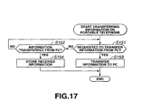
FIG. 17 is a flowchart which shows operations of the portable telephone inFIG. 15 ; -
FIG. 18 shows an example of a connection board; -
FIG. 19 is a block diagram showing a configuration example of the connection board inFIG. 18 ; -
FIG. 20 is a block diagram showing a configuration example of a digital camera inFIG. 18 ; -
FIG. 21 is a flowchart which shows processes of the connection board inFIG. 18 ; -
FIG. 22 is a flowchart which shows processes of the PDA inFIG. 18 ; -
FIG. 23 is a flowchart which shows processes of the digital camera inFIG. 18 ; -
FIG. 24 shows an example of interchanging data between a portable telephone and a headphone; -
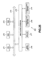
FIG. 25 is a block diagram showing a configuration example of the headphone inFIG. 24 ; -
FIG. 26 is a block diagram showing a configuration example of the portable telephone inFIG. 24 ; -
FIG. 27 is a flowchart which shows process of the portable telephone inFIG. 24 ; -
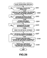
FIG. 28 is a flowchart which shows process of the headphone inFIG. 24 ; -
FIGS. 29A and 29B show examples of transfer characteristics of a human body; -
FIGS. 30A and 30B are characteristic charts for explaining the relationship between electric field strength and distance from an antenna; -
FIG. 31 is a block diagram showing a configuration example of the personal computer in a communication system to which the present invention is applied; -
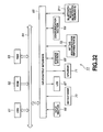
FIG. 32 is a block diagram showing a configuration example of the portable telephone in the communication system to which the present invention is applied; and -
FIG. 33 is a flowchart which shows processes of the communication system to which the present invention is applied. - An example information processing system useful for understanding the present invention, though not within the scope of the claims, has the configuration as shown in
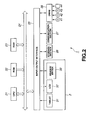
FIG. 1 . The information processing system inFIG. 1 contains apersonal computer 1 comprising aninput display section 2 and abody 3 connected thereto. Theinput display section 2 displays specified information and allows input of specified information by means of operations of a pen (not shown) etc. thereupon. - When a user places e.g. a
portable telephone 11 on theinput display section 2 as needed, data can be interchanged between theportable telephone 11 and thepersonal computer 1. - The
personal computer 1 used here has the configuration as shown inFIG. 2 . Thepersonal computer 1 contains a CPU (Central Processing Unit) 21 which executes various processes according to a program stored in ROM (Read Only Memory) 22 or astorage section 26.RAM 23 appropriately stores programs executed by theCPU 21, data, etc. TheCPU 21, theROM 22, and theRAM 23 are connected to each other via abus 24. Thebus 24 connects with an input/output interface 25. The input/output interface 25 connects with theinput display section 2, thestorage section 26 comprising a hard disc, etc., and acommunication section 27 communicating with theportable telephone 11, e.g., via a telephone line. - The
input display section 2 is provided with atransparent tablet 31 and anLCD 32. Thetablet 31 detects a user's pen operation. TheLCD 32 is placed under thetablet 31 and displays images such as characters, shapes, etc. Theinput display section 2 is further provided with a reader/writer 33 which communicates with an RF tag 72 (seeFIG. 3 ) for theportable telephone 11. - The input/
output interface 25 further connects with adrive 28. Thedrive 28 is configured to appropriately install amagnetic disc 41, anoptical disc 42, a magnet-optical disc 43,semiconductor memory 44, etc. A program is read from themagnetic disc 41 through thesemiconductor memory 44 and is supplied to thestorage section 26 from thedrive 28 via the input/output interface 25. -
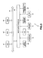
FIG. 3 shows a configuration example of theportable telephone 11. ACPU 61 through an input/output interface 65 basically have the same functions as those for theCPU 21 through the input/output interface 25 for thepersonal computer 1 inFIG. 2 , and detailed descriptions thereof are omitted. - In the
portable telephone 11, an input/output interface 65 connects with aninput section 66 comprising various buttons, switches, etc., and with an LCD (Liquid Crystal Display) 67 for displaying specified information. The input/output interface 65 further connects with astorage section 68 comprising semiconductor memory, etc. and acommunication section 69 for performing communication via a telephone line. - A
microphone 70 receives a voice signal from a user. Aspeaker 71 outputs a voice signal to a user. AnRF tag 72 contains an IC, communicates with the reader/writer 33 of thepersonal computer 1, and sends an internally stored identification number of theportable telephone 11 to the reader/writer 33. TheRF tag 72 has a function to store data supplied from the reader/writer 33 in built-in memory. - The following describes operations of the
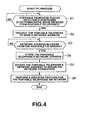
personal computer 1 and theportable telephone 11 with reference to flowcharts inFIGS. 4 and5 . When a user wants to perform processing such as interchanging data between theportable telephone 11 and thepersonal computer 1, he or she places theportable telephone 11 on a specified position of theinput display section 2. For example, this position is indicated by a dotted line inFIG. 1 where the reader/writer 33 is arranged. The user does not need to always place theportable telephone 11 on this position. He or she just needs to bring theportable telephone 11 close to the specified position of theinput display section 2 so that theportable telephone 11 can receive an electromagnetic wave from the reader/writer 33. - The reader/
writer 33 periodically transmits an electromagnetic wave at a sufficiently short cycle. When theportable telephone 11 is placed on theinput display section 2, electromagnetic coupling occurs between the reader/writer 33 and theRF tag 72 for theportable telephone 11, changing an equivalent impedance of the antenna in the reader/writer 33. At step S1 inFIG. 4 , the reader/writer 33 monitors this impedance change to determine whether theportable telephone 11 is placed or is closely positioned, and waits until theportable telephone 11 is placed or closely positioned. - When the
portable telephone 11 is placed on the reader/writer 33 or is positioned close thereto, the reader/writer 33, at step S2, requests theportable telephone 11 to send a network address. Since the network comprises a public telephone line in this case, the reader/writer 33 requests to send a telephone number of theportable telephone 11. - Based on this request, the
portable telephone 11 sends the network address (telephone number). At step S3, the reader/writer 33 waits until it receives the network address from theportable telephone 11. Upon reception of the network address, the reader/writer 33 proceeds to step S4 and supplies theCPU 21 with the network address (telephone number) of theportable telephone 11. TheCPU 21 supplies this telephone number to theRAM 23 for storage. - At step S5, the
CPU 21 controls thecommunication section 27 to access the network address, stored at step S4, of theportable telephone 11 for establishing a network connection. More specifically, thecommunication section 27 generates a call to the telephone number stored in theRAM 23 and makes a telephone line connection between thepersonal computer 1 and theportable telephone 11. - Thereafter, at step S6, the
personal computer 1 performs a specified process with theportable telephone 11 via the network. An example of this process will be described later. - At step S11 in
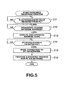
FIG. 5 , theRF tag 72 of theportable telephone 11 determines whether or not to receive an electromagnetic wave from the reader/writer 33 of thepersonal computer 1. Namely, theRF tag 72 determines whether or not theportable telephone 11 is placed on theinput display section 2 of thepersonal computer 1 or is positioned close thereto. When it is determined that theportable telephone 11 is placed on theinput display section 2 or is positioned close thereto, the process proceeds to step S12. TheRF tag 72 waits until it is requested to send a network address. As mentioned above, the reader/writer 33 of thepersonal computer 1 requests theportable telephone 11 to transmit a network address at step S2. When it is determined that this transmission request is received, the process proceeds to step S13. TheRF tag 72 reads the network address of theportable telephone 11, i.e., the telephone number in this case and sends it to the reader/writer 33. That network address (telephone number) is stored in the internal memory. - A network address can be also stored in the
ROM 62 and thestorage section 68. In this case, an address is read by theCPU 61 from these storage locations and is sent from theRF tag 72. - At step S14, the
CPU 61 for theportable telephone 11 waits until it receives an access from thepersonal computer 1 by using thecommunication section 69 via the network. In this case, theCPU 61 waits until it is read via the telephone line. - When the
communication section 69 determines at step S14 that a call is received from thecommunication section 27 of thepersonal computer 1, the process proceeds to step S15. In response to this, a connection is established between the portable telephone and thepersonal computer 1 via the network. In this case, the telephone line is connected. - The process then proceeds to step S16. A specified process is performed between the
portable telephone 11 and thepersonal computer 1 via the network. This process corresponding to the process at step S6 inFIG. 4 . - In the aforementioned example, the telephone number of the
portable telephone 11 is sent and received as identification information. It may be preferable to send an identification number other than the telephone number of theportable telephone 11 from this telephone to thepersonal computer 1. Based on that identification number, thepersonal computer 1 may retrieve the telephone number of theportable telephone 11 as a network address. -
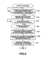
FIGS. 6 and7 describe operations of thepersonal computer 1 and theportable telephone 11, respectively, in this case. - Processes at steps S51 through S56 for the
portable telephone 11 inFIG.7 are basically the same as those at steps S11 through S16 inFIG. 5 . A difference fromFIG. 5 is that, instead of the telephone number, an identification number itself is requested from thepersonal computer 1 at step S52 and is transmitted at step S53. The other processes are the same as those inFIG. 5 . - Likewise, processes at steps S31 through S37 in
FIG. 6 for thepersonal computer 1 are basically the same as those at steps S1 through S6 inFIG. 4 . InFIG. 6 , however, theportable telephone 11 sends an identification number, not the telephone number. At step S34, theCPU 21 of thepersonal computer 1 stores the identification number for theportable telephone 11 in theRAM 23. Then, at step S35, theCPU 21 retrieves the telephone number as a network address based on the identification number for theportable telephone 11. For this retrieval, it may be preferable to use thestorage section 26 to previously store a table for correspondence between identification numbers and telephone numbers for theportable telephone 11. Thecommunication section 27 may access a specified server e.g. via the Internet, etc. to retrieve a telephone number corresponding to the identification number for theportable telephone 11 via the server. - After the telephone number for the
portable telephone 11 is retrieved, subsequent processes are the same as those inFIG. 4 . - The following further describes an example of processes at step S6 in
FIG. 4 (step S37 inFIG. 6 ) and at step S16 inFIG. 5 (step S56 inFIG. 7 ). -
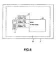
FIG. 8 shows an example of placing theportable telephone 11 on theinput display section 2 or positioning it close thereto. In this example, theLCD 32 of theinput display section 2 is used to display the content of mail registered in theportable telephone 11 with an enlarged display size. - Hereinafter, processes for the
portable telephone 11 and thepersonal computer 1 are described with reference to flowcharts inFIGS. 9 and10 . - At step S71, the
CPU 61 of theportable telephone 11 reads senders and subjects of so far received mail messages stored in theRAM 63. At step S72, theCPU 61 sends senders and subjects of the read mail to thepersonal computer 1. Namely, at this time, theCPU 61 controls thecommunication section 69 to transmit these senders and subjects to thepersonal computer 1 via the telephone line. - As will be described later, the transmitted mail senders and subjects are displayed on the
LCD 32 of thepersonal computer 1. When the user selects a specified mail message out of the displayed ones, the selected mail message is transmitted to theportable telephone 11. - At step S73, the
CPU 61 waits until selection of the mail is notified. When the mail selection is notified, the process proceeds to step S74. TheCPU 61 reads the content of the selected mail from theRAM 63 and allows thecommunication section 69 to transmit that content to thepersonal computer 1. - In response to this process of the
portable telephone 11, thepersonal computer 1 performs the process as shown in the flowchart ofFIG. 10 . - At step S81, the
CPU 21 receives the mail senders and subjects if they are transmitted from theportable telephone 11. Namely, when the mail senders and subjects are transmitted from thecommunication section 69 of theportable telephone 11 via the telephone line, thecommunication section 27 receives them and supplies them to theRAM 23 for storage. At step S82, theCPU 21 reads the senders and subjects stored in theRAM 23 and outputs them to theLCD 32 for display. In this manner; as shown inFIG. 8 for example, awindow 91 displays the mail senders and subjects transmitted from theportable telephone 11. - Viewing this display, the user operates a pen to select a mail message by selecting the sender or the subject of one mail message in the
window 91. At step S83, theCPU 21 waits until a mail message is selected. When the mail message is selected, the process proceeds to step S84. TheCPU 21 notifies theportable telephone 11 of the selected mail message. Namely, at this time, theCPU 21 controls thecommunication section 27 to notify theportable telephone 11 of the mail message specified (selected) by the user via the telephone line. - When the selected mail message is notified, the
portable telephone 11 transmits the content of the selected mail message as mentioned above. At step S85, thecommunication section 27 receives the mail content transmitted from theportable telephone 11. This mail content is temporarily supplied to theRAM 23 for storage. At step S86, theCPU 21 reads the mail content stored in theRAM 23. TheCPU 21 outputs and displays the mail content at the right of the position where theportable telephone 11 is placed on theLCD 32 or at a position specified by the user with the pen, i.e., detected from an output of thetablet 31. In this manner, as shown inFIG. 8 for example, thewindow 92 displays the selected mail content. In the example ofFIG. 8 , the second mail message is selected in thewindow 91, showing that the sender is BBB, the subject is bb, and the content is "Hello! It's fine today". - Theoretically, it is possible to interchange mail data by means of communication between the
RF tag 72 and the reader/writer 33. Since this communication permits just a small transmission capacity, however, it is used only for transmission of the identification information. -
FIG. 11 shows another example of data transferred to/from thepersonal computer 1 via the telephone line. In this example, aPDA 101 instead of theportable telephone 11 is placed on or is positioned close to theinput display section 2. Image data stored in thePDA 101 is transferred to thepersonal computer 1. - For example, the
PDA 101 is configured as shown inFIG. 12 - A
CPU 111 through an input/output interface 115 have the same functions as those for theCPU 21 through the input/output interface 25 of thepersonal computer 1 inFIG. 2 . - An
input section 116 comprises button, switches, etc. and is operated by the user for entering specified instructions. A tablet 127 comprises a transparent member and detects an input generated when the user operates a pen (not shown), etc. AnLCD 118 is arranged under thetablet 117 and displays characters, shapes, etc. - Plate-shaped
IC memory 119 contains semiconductor memory and can be attached or detached from thePDA 101. Here, amemory stick 119 is used as the IC memory and appropriately stores text data or image data. Acommunication section 120 communicates with other apparatuses via the telephone line. - An
RF tag 121 internally stores a telephone number (or identification number) of thePDA 101. TheRF tag 121 may be replaced byROM 112 or thememory stick 119. - Referring now to flowcharts in
FIGS. 13 and 14 , the following describes an example of processing performed when thePDA 101 is placed on theinput display section 2 of thepersonal computer 1 as shown inFIG. 11A . - As mentioned above, when the
PDA 101 is placed on theinput display section 2 of thepersonal computer 1, the telephone line is connected between thepersonal computer 1 and thePDA 101. - When the user instructs transfer of an image, the
CPU 111 of thePDA 101 selects one of image data previously stored in thememory stick 119 at step S101 inFIG. 13 . At step S102, theCPU 111 controls thecommunication section 120 to transmit the selected image data to thepersonal computer 1 via the telephone line. - At step S103, the
CPU 111 determines whether or not all image data is transmitted. When image data remains being unsent, theCPU 111 returns to step S101 and repeatedly performs the subsequent process. - When it is determined that all image data is transmitted at step S103, the process terminates.
- Incidentally, the
personal computer 1 performs the process as shown in the flowchart ofFIG. 14 . When image data is transmitted from thePDA 101 via the telephone line, theCPU 21 receives the data via thecommunication section 27 at step S111 and supplies the data to theRAM 23 for temporary storage. At step S112, theCPU 21 reads the imaged data stored in theRAM 23 and outputs it to theLCD 32 for display. - As shown in
FIG. 11A , for example, thePDA 101 stores five images P1 through P5. As shown inFIG. 11B , one image P1 is transferred from thePDA 101 to thepersonal computer 1. This image is stored in theRAM 23 and is displayed on theLCD 32. According to the example inFIG. 11B , the image is displayed at the upper left of thePDA 101. The image can be displayed at a position specified by the pen. At this time, the transferred image disappears from theLCD 118 of thePDA 101. The example inFIG. 11B shows the transfer of one image P1 out of five images P1 through P5 inFIG. 11A . TheLCD 118 of thePDA 101 displays four images P2 through P5. - At step S113, the
CPU 21 determines whether or not all the received image data are displayed. When image data remains being undisplayed, theCPU 21 returns to step S111 and repeatedly performs the aforementioned process. When it is determined that all the received image data are displayed, the process terminates. - As shown in
FIGS. 11C through 11F , images are sequentially transferred from thePDA 101 to thepersonal computer 1 in the order of P2, P3; P4, and P5 and are stored in theRAM 23. In accordance with this transfer, theLCD 32 sequentially displays images P2 through P5. As images are displayed in this manner, transferred images are sequentially deleted from theLCD 118 of thePDA 101. -
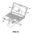
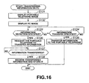
FIG. 15 shows another example of interchanging information. In this example, the personal computer is replaced by a notebook computer. The reader/writer 33 of thepersonal computer 1 inFIG. 2 is arranged to the bottom of apalm rest 152A on thispersonal computer 151. The internal structure of thepersonal computer 151 is the same as that shown inFIG. 2 , and its specific illustration is omitted. - Hereinafter, processes for the
personal computer 151 and theportable telephone 11 in this case are described with reference to flowcharts inFIGS. 16 and17 . The configuration of thepersonal computer 1 inFIG. 2 is used as is for that of thepersonal computer 151. Also in this case, placing theportable telephone 11 on thepalm rest 152A of thepersonal computer 151 connects the telephone line between theportable telephone 11 and thepersonal computer 151 as mentioned above. - At step S131 in
FIG. 16 , theCPU 21 of thepersonal computer 151 displays an image representing theportable telephone 11 on theLCD 32. In the example ofFIG. 15 , animage 161 is displayed as the image of theportable telephone 11. Thisimage 161 is displayed to the right of theLCD 32 when theportable telephone 11 is placed to the right of thepalm rest 152A. It is displayed to the left of theLCD 32 when theportable telephone 11 is placed to the left of thepalm rest 152A. - At step S132, the
CPU 21 displays animage 162 inFIG. 15 on theLCD 32 as an image representing thepersonal computer 1. - At step S133, the
CPU 21 determines whether or not the user specifies information reception. When it is determined that no information reception is specified, theCPU 21 proceeds to step S134 to determine whether or not information transfer is specified. When it is determined that no information transfer is specified either, theCPU 21 returns to step S133 ands repeatedly performs the subsequent process. - When it is determined that the user specifies information transfer at step S134, the process proceeds to step S135. The
CPU 21 performs a process for transferring information to theportable telephone 11. - On the
LCD 32 inFIG. 15 , for example, the user can specify information transfer by performing a drag-and-drop operation from theimage 162 for thepersonal computer 151 to theimage 161 for theportable telephone 11 in the direction of an arrow A. In this case, theCPU 21 transfers specified data stored in theRAM 23 from thecommunication section 27 to theportable telephone 11 via the telephone line. - When it is determined at step S133 that information reception is specified, the process proceeds to step S136. The
CPU 21 requests theportable telephone 11 to transfer information. - Namely, in
FIG. 15 , the user can specify information transfer from theportable telephone 11 to thepersonal computer 151 by performing a drag-and-drop operation from theimage 161 to theimage 162 in the direction of an arrow B. In this case, theCPU 21 controls thecommunication section 27 to request theportable telephone 11 to transfer information via the telephone line. - When requested for information transfer, the
portable telephone 11 transfers information as will be described later. At step S137, theCPU 21 waits until information is transferred. When information is transferred, the process proceeds to step S138. TheCPU 21 receives the transferred information via thecommunication section 27 and stores the information in theRAM 23. - The
portable telephone 11 performs the process as shown in the flowchart ofFIG. 17 in response to the aforementioned operations of thepersonal computer 151. At step S151, theCPU 61 determines whether or not a request for information transfer is received from thepersonal computer 151. When such request is not received, the process proceeds to step S152. TheCPU 61 determines whether or not information is transferred from thepersonal computer 151. When no information is transferred, theCPU 61 returns to step S151 and repeatedly performs the subsequent process. - When it is determined at step S151 that a request for information transfer is received from the
personal computer 151, theCPU 61 proceeds to step S153. TheCPU 61 then reads information stored in theRAM 63 and transfers the information to thepersonal computer 151 from thecommunication section 69 via the telephone line. - When it is determined at step S152 that information is transferred from the
personal computer 151, theCPU 61 proceeds to step S154. TheCPU 61 then supplies the information received at thecommunication section 69 via the telephone line to theRAM 63 for Storage. -
FIG. 18 shows as an embodiment of the invention a connection board. When two electronic devices are placed on aconnection board 171, the telephone line is connected between the two devices, allowing data to be interchanged via the telephone line. - In the example of
FIG. 18 , thePDA 101 and adigital camera 181 are placed on theconnection board 171. - The
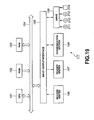
connection board 171 is configured as shown inFIG. 19 , for example. ACPU 191 through an input/output interface 195 are basically the same as theCPU 21 through the input/output interface 25 inFIG. 2 . - Reader/
writers communication section 198 performs communication between two electronic devices via the telephone line. - A
drive 199 is configured to appropriately install amagnetic disc 211, anoptical disc 212, a magnet-optical disc 213,semiconductor memory 214, etc. A program stored there is read appropriately and is transferred to RAM 193 for storage.FIG. 20 shows an example of an internal configuration of thedigital camera 181. ACPU 231 through an input/output interface 235 are basically the same as theCPU 21 through the input/output interface 25 inFIG. 2 . - An
input section 236 comprises button, switches, etc. and is operated by the user for entering specified instructions. AnLCD 237 displays an image captured by animage pickup section 239 or an image stored in amemory stick 238 orRAM 233. Thememory stick 238 can be attached or detached from thedigital camera 181 and stores images captured by theimage pickup section 239. AnRF tag 241 internally stores the telephone number as an identification number of thedigital camera 181. TheRF tag 241 performs communication with the reader/writer 196 of theconnection board 171. Acommunication section 240 provides communication via the telephone line. - First, with reference to the flowchart in
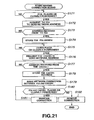
FIG. 21 , the following describes a process of theconnection board 171 for establishing connection when two electronic devices (PDA 101 anddigital camera 181 in this case) are placed or moved close to each other on theconnection board 171. - At step S171, the
CPU 191 of theconnection board 171 determines whether or not the first PDA is placed or closely positioned. Namely, it determines whether or not the reader/writer writer writer 196 detects that thePDA 101 is placed, the reader/writer 196 requests thePDA 101 to send a telephone number. In response to this request, thePDA 101 sends its telephone number. At this time, thePDA 101 performs the same process as that described for theportable telephone 11 according to the flowchart inFIG. 5 . At step S173, theCPU 191 of theconnection board 171 waits until the telephone number of thePDA 101 is sent. When the telephone number is sent, theCPU 191, at step S174, supplies the telephone number to theRAM 193 for storage. - At steps S175 through 178, the other of the reader/
writers 196 and 197 (reader/writer 197 in this case) performs the same process as that for the aforementioned steps S171 through S174. - In this case, the telephone number of the
digital camera 181 is read from theRF tag 241 of thedigital camera 181. The telephone number is supplied to theRAM 193 of theconnection board 171 for storage. - At step S179, the
CPU 191 of theconnection board 171 establishes telephone line connection between thePDA 101 and thedigital camera 181 whose addresses are stored at steps S174 and S178, respectively. This allows thePDA 101 and thedigital camera 181 to interchange data with each other via the telephone line. - At step S180, the
CPU 191 of theconnection board 171 determines whether or not the two PDAs (PDA 101 and digital camera 191) remain being placed or closely positioned. When they remain being placed or closely positioned, theCPU 191 proceeds to step S181 to maintain the connection established at step S179. - The process then returns to step S180. As long as the
PDA 101 and thedigital camera 181 are placed or closely positioned on theconnection board 171, the connection between thePDA 101 and thedigital camera 181 is maintained. - When a user removes at least one of the
PDA 101 and thedigital camera 181 from theconnection board 171, it is determined at step S180 that either of the two devices is not placed or closely positioned. TheCPU 191 proceeds to step S182 to remove the connection established at step S179. This disables thePDA 101 and thedigital camera 181 from communicating with each other via the telephone line subsequently. - Referring now to flowcharts in
FIGS. 22 and23 , the following describes an example of a process between thePDA 101 and thedigital camera 181 when they are placed or closely positioned on theconnection board 171. - At step S201 in
FIG. 22 , theCPU 111 of thePDA 101 determines whether or not a user specifies information reception. When not specified, theCPU 111 proceeds to step S202 to determines whether or not information transfer is specified. When information transfer is not specified either, theCPU 111 returns to step S201 and repeatedly performs the subsequent process. - When it is determined at step S202 that the user specifies information transfer, the process proceeds to step S206. The
CPU 111 reads data stored in thememory stick 119 and transfers the data to thedigital camera 181 from thecommunication section 120 via the telephone line. - For example, the user may perform an input operation in the direction as indicated by an arrow C in
FIG. 18 . In this case, theCPU 111 assumes the operation to be an instruction for transferring data from thePDA 101 to thedigital camera 181 and performs the aforementioned process. - When it is determined at step S201 that the information reception is specified, the
CPU 111 proceeds to step S203 and requests thedigital camera 181 to transfer information. As will be described later, thedigital camera 181 transfers the information upon reception of this request. At step S204, theCPU 111 waits until the information is transferred. When the information is transferred, theCPU 111, at step S205, uses thecommunication section 120 to receive the transferred information via the telephone line and supplies this information to thememory stick 119 for storage. - This process is performed when the user operates the pen on the
tablet 117 in the direction indicated by an arrow D inFIG. 18 , i.e., from thedigital camera 181 to thePDA 101. - Referring now to a flowchart in
FIG. 23 , the following describes a process for thedigital camera 181. - At step S221, the
CPU 231 of thedigital camera 181 determines whether or not a request for information transfer is received from thePDA 101. When no information transfer is requested, theCPU 231 proceeds to step S222 to determine whether or not information is transferred from thePDA 101. When no information is transferred, theCPU 231 returns to step S221 and repeatedly performs the subsequent process. - When it is determined at step S221 that a request for information transfer is received from the PDA, the process proceeds to step S223. The
CPU 231 then reads image data stored in thememory stick 238 and transfers the data to thePDA 101 from thecommunication section 240 via the telephone line. - When it is determined at step S222 that information is transferred from the
PDA 101, the process proceeds to step S224. TheCPU 231 then supplies the information received at thecommunication section 240 via the telephone line to thememory stick 238 for storage. - In this example, as mentioned above, two electronic devices can interchange information when they are placed or closely positioned on the
connection board 171. A user can intuitively and safely manage information by controlling the security which permits information transfer only between two electronic devices placed on the same plane. -
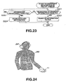
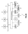
FIG. 24 shows another embodiment which is not within the scope of the claims. This embodiment interchanges an identification number via a user's human body. In this example, the user wears aheadphone 261 on his or her head and holds theportable telephone 11 in his or her hand. The identification number is interchanged between theheadphone 261 and theportable telephone 11 via the user'shuman body 260. - The
headphone 261 is configured as shown inFIG. 25 , for example. ACPU 271 through an input/output interface 275 are basically the same as theCPU 21 through the input/output interface 25 inFIG. 2 . - An
input section 276 is operated by the user to start or stop using theheadphone 261. Aspeaker 277 generates a voice signal received via acommunication section 279. Acommunication section 278 communicates with theportable telephone 11 via thehuman body 260. Thecommunication section 279 performs wireless communication via the telephone line. - The
portable telephone 11 is configured basically the same as shown inFIG. 3 . In this example, as shown inFIG. 26 , theRF tag 72 inFIG. 3 is replaced by acommunication section 291. Thecommunication section 291 communicates with thecommunication section 278 of theheadphone 261 via thehuman body 260. - Otherwise, the
portable telephone 11 is configured the same as shown inFIG. 3 . - Referring now to a flowchart in
FIG. 27 , the following describes a process for theportable telephone 11 in the example ofFIG. 24 . - At step S241, the
CPU 61 of theportable telephone 11 determines whether or not theheadphone 261 is detected by using thecommunication section 291 to communicate with thecommunication section 278 of theheadphone 261 via thehuman body 260. When theheadphone 261 is not detected, theCPU 61 waits until it is detected. This detection process is performed in such a manner that thecommunication section 291 periodically outputs a signal requesting a response and theCPU 61 checks for a response to the request. - When it is determined at step S241 that the
headphone 261 is detected (response returned), the process proceeds to step S242. TheCPU 61 requests theheadphone 261 to send its network address. As will be described later with reference to a flowchart inFIG. 28 , theheadphone 261 responds to this request and sends its network address at step S266. - At step S243, the
CPU 61 of theportable telephone 11 waits until it receives the network address from theheadphone 261 via thecommunication section 291. When receiving that address, theCPU 61 proceeds to step S244 to supply the received network address of theheadphone 261 to thestorage section 68 for storage.
Then proceeding to step S245, theCPU 61 waits until it is requested to send the network address from theheadphone 261. When requested, theCPU 61 proceeds to step S246 to send the network address of theportable telephone 11 from thecommunication section 291 to theheadphone 261 via thehuman body 260. That network address is previously stored in thestorage section 68. - At step S247, the
CPU 61 determines whether or not a network connection is made to theheadphone 261. When a connection is not established yet, the process proceeds to step S248. TheCPU 61 accesses the network address of theheadphone 261 stored at step S244 to establish a network connection. Specifically, theCPU 61 controls thecommunication section 69 to generate a call to the telephone number stored at step S244 as a network address of theheadphone 261, connecting the telephone line. - When it is determined at step S247 that a connection is already established, the process at step S248 is skipped.
- At step S249, the
CPU 61 of theportable telephone 11 performs a specified process for theheadphone 261 via the telephone line connected by thecommunication section 69. - Corresponding to this operation for the
portable telephone 11, theheadphone 261 performs a process as shown by a flowchart inFIG. 28 . The process at steps S261 through S269 is basically the same as that at steps S241 through S249 for theportable telephone 11 inFIG. 27 except that the target differs. - At step S267, the
headphone 261 also determines whether or not a network connection is made to theportable telephone 11. For example, the process at step S268 is skipped when the telephone line is already connected to theportable telephone 11 due to the aforementioned process at step S248 for theportable telephone 11. - In other words, the process at step S248 for the
portable telephone 11 is skipped when the telephone line is already connected due to the process on theheadphone 261. - In this example, the
portable telephone 11 and theheadphone 261 each acquire the identification number of the other as mentioned above. Based on the identification number, one makes a connection to the other via the telephone line. - For example, a user, wearing the
headphone 261, may use theportable telephone 11 to access a given music distribution server and receive music data. In this case, the distributed music data can be transmitted from theportable telephone 11 to theheadphone 261 via the telephone line connected between theportable telephone 11 and theheadphone 261. The user can listen to the music using theheadphone 261 even if he or she does not hold theportable telephone 11. - Wearing the
headphone 261 equipped with a microphone, the user may use theportable telephone 11 to call the other party. When the other party responds, the user can thereafter speak to the other party just by using theheadphone 261 without holding theportable telephone 11. - Further, for example, the aforementioned body of the
personal computer 1 and a mouse used for it each can be provided with communication sections enabling communication via the user'shuman body 260. The user interchanges identification numbers between them by touching the mouse and the personal computer body. Based thereon, the telephone line is connected therebetween. Thereafter, the user can send a signal corresponding to a mouse operation to the personal computer by operating the mouse without touching the personal computer body. -
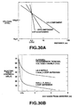
FIG. 29 shows transfer characteristics of a human body. In characteristic charts ofFIGS. 29A and 29B , a spectrum analyzer is used to measure transfer characteristics of a human body (between both hands) within the range from 1 to 20 MHz inFIG. 29A and within the range from 1 to 30 MHz inFIG. 29B . In either case, a coaxial cable is connected to a tracking generator and an input terminal. During the experiment, coaxial cable grounds (GND) are connected to each other in order to prevent an antenna effect.FIGS. 29A and 29B show approximately flat transfer characteristics within the range around from 1 to 20 MHz, resulting in the attenuation of 30 through 40 dB. - For the measurement in
FIGS. 29A and 29B , the tracking generator's output impedance and the spectrum analyzer's input impedance are both 75 Ω. Accordingly, if the impedance between both hands is one megohm from the viewpoint of an alternating current, the attenuation should be at lest -80 dB. Actually, however, the attenuation is very small. It can be understood that this proves a possibility of signal transmission via the human body. - The data transmission side can be considered to be a micro-dipole antenna. There is fully analyzed the state of an electromagnetic field generated by this antenna. According to such analysis result, an electromagnetic field generated by the human body is equivalent to that generated by the micro-dipole antenna. The electromagnetic field strength is represented by a vector sum of components which are in inverse proportion to distance R from the antenna, the second power of distance R, and the third power of distance R. These components are respectively referred to as the radiant field, the induction field, and the electrostatic field. Relational expressions for these are described in detail in Japanese Patent Application Laid-Open Publication No.
7-170215 -
FIGS. 30A and 30B depict electric field strengths.FIG. 30A is a characteristic chart showing the relationship between an electric field strength for each of the aforementioned and a distance from antennas.FIG. 30B shows electric field strengths and distances for a λ/2.2 dipole antenna and a 3.4 cmφ loop antenna, and 8 cmφ and 3.4 cmφ loop antennas under the conditions of frequency f = 200 MHz and a transmission terminal voltage = 100 dBµV (75 Ω). As shown inFIGS. 30A and 30B , strengths of the aforementioned radiant field (1/R component), induction field (1/(the second power of R) component), and electrostatic field (1/(the third power of R) component) are equaled for the length of λ/2π. When the distance is smaller than this value, the strengths increase drastically. When f = 11 MHz, this distance becomes 4.3 m. Accordingly, it is desirable to adopt a transmission system which mainly uses the electrostatic field. - It is preferable to select a range of electric field strength available under no legal restrictions on the electromagnetic interference (EMI). For example, the frequency should be 332 MHz or less, and the electric field strength should be 500 µV/M or less.
- As mentioned above, the electrostatic field attenuates on the basis of the third power of distance R. When the distance changes from 1 m to 3 m, for example, the electric field strength attenuates 1/27 (=1/(3×3×3)). Accordingly, the signal strength extremely attenuates as the distance from a data transmission means increases. Even if a plurality of users uses similar apparatuses, it is hardly possible to detect the other users' signals as noises. Under a working condition where there are many users carrying similar apparatuses adjacent to each other, for example, mainly using the electrostatic field enables excellent communication.
- The
human body 260 touches part of thecommunication sections portable telephone 11 and theheadphone 261. It is desirable to provide a wide area to this contact point. Examples of the contact point include a wrist watch, necklace, ring, bracelet, belt, shoe etc. which can be wound curvedly around a human body's finger, arm, neck, etc. Namely, it is preferable to configure the contact point so that it can touch the human body's skin as widely as possible. - In the aforementioned example, the RF tag and the reader/writer interchange identification numbers. It is also possible to interchange identification numbers by printing a bar code on each electronic device and reading the bar code.
- Further, it is possible to use not only the input display section and the notebook computer's palm rest, but also a mouse pad or a white board as information processing apparatuses on which an electronic device should be placed.
- The identification number has been explained by using the telephone number as an example but is not limited thereto if it is needed to access the electronic device on the network.
- It may be preferable to authenticate the other party by interchanging the identification number.
- In the aforementioned description, the telephone line is used as an example of the network. It is also possible to use a LAN, wireless LAN, WAN, Internet, or Bluetooth applicable to various portable devices, etc.
- The following describes a communication system which allows the RF tag and the reader/writer to interchange various information and establishes Bluetooth communication based on the obtained information.
- This communication system is configured the same as the information processing system in
FIG. 1 . Thepersonal computer 1 and theportable telephone 11 inFIG. 1 respectively use the reader/writer 33 and theRF tag 72 to send and receive various information and perform Bluetooth communication based on the interchanged information. Namely, a Bluetooth module is built in each of thepersonal computer 1 and theportable telephone 11. -
FIG. 31 is a block diagram showing a configuration example of thepersonal computer 1 containing a Bluetooth module. - The
personal computer 1 inFIG. 31 is configured basically the same as thepersonal computer 1 inFIG. 2 and differs from the latter as follows. First, aBluelooth module 301 is provided. Second, as will be described later, the reader/writer 33 notifies its identification information to theportable telephone 11 by means of an electromagnetic wave. - The
Bluetooth module 301 communicates with a Bluetooth module 311 (seeFIG. 32 ) provided in theportable telephone 11 according to Bluetooth. - Bluetooth is a wireless communication specification standardized by the Bluetooth SIG (Special Interest Group). Bluetooth provides communication with another device provided with a Bluetooth module (appropriately referred to as a Bluetooth device) by using a 2.4 GHz band, i.e., an IMS (Industrial Science Medical) band.
- A Bluetooth-based network is called a piconet or a scatternet comprising a plurality of piconets connected with each other according to its form. The network contains Bluetooth devices working as a master and a slave. Hereinafter, a master Bluetooth device is just referred to as a master, and a slave Bluetooth device is just referred to as a slave appropriately.
- When the master starts communicating with a slave, the master generates a radio wave at a specified cycle for detecting the slave. When the slave responds accordingly, the master specifies a slave Bluetooth device based on various information sent from the slave and starts communication. Information notified to the master from the slave contains Bluetooth addresses specific to respective Bluetooth devices (modules). Based on a Bluetooth address, the master specifies the slave to communicate with.
- Namely, the
Bluetooth module 301 inFIG. 31 is also assigned with a specific Bluetooth address which is assumed to be the same as identification information (ID) of the reader/writer 33 in this communication system example. As shown inFIG. 31 , the identification information of the reader/writer 33 is defined as identification information A. The address of theBluetooth module 301 is defined as Bluetooth address A. - The
portable telephone 11 inFIG. 32 is configured basically the same as theportable telephone 11 inFIG. 3 and differs from the latter as follows. First, aBluetooth device 311 is provided. Second, theRF tag 72 notifies its identification information, not the telephone number, to the reader/writer 33. - In this
portable telephone 11, the identification information of theRF tag 72 is defined as identification information B. The address of theBluetooth module 311 is defined as Bluetooth address B. The identification information of theRF tag 72 need not always be the same as the address of theBluetooth module 311. The identification information just needs to include the address. - When receiving an electromagnetic wave generated from the reader/
writer 33, theRF tag 72 notifies identification information B accordingly. Based on identification information B obtained by the reader/writer 33, theBluetooth module 301 of thepersonal computer 1 searches for a Bluetooth device having the same Bluetooth address (Bluetooth address B) for establishing communication with theBluetooth module 311 of theportable telephone 11. - With reference to a flowchart in
FIG. 33 , the following describes a process for making communication between theBluetooth module 301 of thepersonal computer 1 and theBluetooth module 311 of theportable telephone 11. In the process ofFIG. 33 , thepersonal computer 1 works as a master and theportable telephone 11 as slave. At step S311, the reader/writer 33 generates an electromagnetic wave for detecting terminals provided with RF tags including theportable telephone 11. As described with reference toFIG. 4 etc., this electromagnetic wave is periodically generated at a sufficiently short cycle. - When receiving the electromagnetic wave at step S321, the
RF tag 72 of theportable telephone 11 proceeds to step S322 to notify the reader/writer 33 of the predetermined identification information B. This identification information (identification information B) of theRF tag 72 is defined to be the same as the address of the Bluetooth module 311 (Bluetooth address B). - At step S312, the reader/
writer 33 receives the identification information (Bluetooth address) notified from theRF tag 72. At step S 313, the reader/writer 33 notifies the received identification information to theBluetooth module 301 via the input/output interface 25. - At step S301, the
Bluetooth module 301 receives the notification from the reader/writer 33. Based on the obtained Bluetooth address, theBluetooth module 301 proceeds to step S302 to search for a Bluetooth device having the address and request the device for connection (i.e., request to start communication). - At step S331, the
Bluetooth module 311 of theportable telephone 11 receives the request from theBluetooth module 301. TheBluetooth module 311 then proceeds to step S332 to start communication with the personal computer 1 (Bluetooth module 301) as a Bluetooth device. - Specifically, there are performed various processes such as synchronization, authentication, etc. for communication. Then, the communication is made between the
personal computer 1 and theportable telephone 11. At steps S303 and S332 and thereafter, various information is sent and received under the Bluetooth environment. In the aforementioned example, thepersonal computer 1 works as master and theportable telephone 11 as slave. Obviously, both may interchange this master/slave arrangement. When a reader/writer is also provided for theportable telephone 11, the latter detects presence of thepersonal computer 1. It may be preferable to establish the Bluetooth communication based on the identification information notified from the RF tag of thepersonal computer 1. - The aforementioned communication system obtains a Bluetooth address by means of communication between the RF tag and the reader/writer and establishes Bluetooth communication based thereon. Such communication system is applicable not only between the
personal computer 1 and theportable telephone 11, but also between various devices. - For example, the aforementioned Bluetooth communication is available between a hand-held device such as a portable telephone or a PDA and an apparatus such as a TV set, a vehicle navigation system, an automatic vending machine, or an ATM (automatic teller machine). In this case, the portable telephone and the PDA just need at least a Bluetooth module and an RF tag. The TV set, the vehicle navigation system, the automatic vending machine, and the ATM each just need at least a Bluetooth module and an RF tag's reader/writer.
- The present invention is also applicable to communication between portable telephones, between PDAs, between a PDA and a digital camera, between a PDA and a digital video camera, etc. if either of communicating parties has the reader/writer.
- In the aforementioned example, the
personal computer 1 specifies a device for communication based on the identification information notified from theRF tag 72. Any information may be available as long as if it is identification information unique to the device. - For example, when each device is assigned with 128-bit IPv6 (Internet Protocol version 6) code, the master
personal computer 1 can specify a device for communication based on the identification information notified from theRF tag 72. - Software can be used to implement a sequence of the aforementioned processes. In this case, a computer contains special hardware in which programs constituting the software are installed. Alternatively, the software is installed from a network or a recording medium, e.g., in a general-purpose personal computer which can perform diverse functions by installing various programs.
- As shown in
FIGS. 2 and19 , the recording medium may be configured independently of the apparatus body in the form of a package medium distributed to users for providing programs. Such recording media include themagnetic discs 41 and 211 (including a floppy disc), theoptical discs 42 and 212 (including CD-ROM (Compact Disc-Read Only Memory) and DVD (Digital Versatile Disc)), the magnet-optical discs semiconductor memory ROM storage section 26, etc. which record programs. - In the present invention, steps describing a program stored in a recording medium include not only a process which is performed chronologically according to the specified sequence, but also a process which is performed concurrently or individually, not always chronologically.
- In the description of the present invention, the system signifies an overall apparatus comprising a plurality of apparatuses.
- The above-described examples obtain identification information about a closely positioned electronic device and communicate with the electronic device via the network based on the identification information. It is possible to easily and reliably interchange data with the electronic device.
- Further, the above-described examples communicate with an information processing apparatus via the network. It is possible to easily and reliably interchange information with the information processing apparatus.
- Moreover, the above-described examples allow the information processing apparatus to obtain identification information of the electronic device when the electronic device is closely positioned over the information processing apparatus. Based on the identification information, communication is made between the electronic device and the information processing apparatus via the network. It is possible to easily and reliably interchange information between the information processing apparatus and the electronic device.
- Furthermore, the above-described examples obtain each identification information of the first and second electronic devices when both are closely positioned. Based on the identification information, communication is made between the first and second electronic devices via the network. It is possible to easily and reliably interchange information between the first and second electronic devices.
Claims (6)
- An information processing apparatus (171) comprising:a first detection means (196) for detecting that a first electronic device (101) is closely positioned to the information processing apparatus by detecting electromagnetic coupling with an RF tag of the first electronic device;a second detection means (197) for detecting that a second electronic device (181) is closely positioned to the information processing apparatus (171) by detecting electromagnetic coupling with an RF tag of the second electronic device;a first acquisition means (196) for acquiring first identification information of said first electronic device (101) from said RF tag of said first electronic device when said first detection means (196) detects that said first electronic device (101) is closely positioned;a second acquisition means (197) for acquiring second identification information of said second electronic device (181) from said RF tag of said second electronic device when said second detection means (197) detects that said second electronic device (181) is closely positioned; anda control means (191) for establishing communication between said first and second electronic devices based on said first and second identification information, said communication taking place via a telephone network.
- The information processing apparatus according to claim 1, wherein said first and second acquisition means (198) obtain an address on said network as said first or second identification information.
- The information processing apparatus according to claim 1, wherein said apparatus further comprises a search means for searching for addresses on said network for said first and second electronic devices based on said first or second identification information.
- The information processing apparatus according to claim 1, wherein said first and second acquisition means include reader/writers which communicate with RF tags provided for said first and second electronic devices to obtain said identification information.
- An information processing method for an information processing apparatus, the method including:a first detection step (S171) for detecting that a first electronic device is closely positioned to the information processing apparatus by detecting electromagnetic coupling with an RF tag of the first electronic device;a second detection step (S175) for detecting that a second electronic device is closely positioned to the information processing apparatus (171) by detecting electromagnetic coupling with an RF tag of the second electronic device;a first acquisition step (S173) for acquiring first identification information of said first electronic device from said RF tag of said first electronic device when a process at said first detection step detects that said first electronic device is closely positioned;a second acquisition step (S177) for acquiring second identification information of said second electronic device from said RF tag of said second electronic device when a process at said second detection step detects that said second electronic device is closely positioned; anda control step (S179) for establishing communication between said first and second electronic devices based on said first and second identification information, said communication taking place via a telephone network.
- A recording medium which records a computer-readable program for controlling an information processing apparatus to perform a method including:a first detection step (S171) for detecting that a first electronic device is closely positioned to the information processing apparatus by detecting electromagnetic coupling with an RF tag of the first electronic device;a second detection step (S175) for detecting that a second electronic device is closely positioned to the information processing apparatus (171) by detecting electromagnetic coupling with an RF tag of the second electronic device;a first acquisition step (S173) for acquiring first identification information of said first electronic device from said RF tag of said first electronic device when a process at said first detection step detects that said first electronic device is closely positioned;a second acquisition step (S177) for acquiring second identification information of said second electronic device from said RF tag of said second electronic device when a process at said second detection step detects that said second electronic device is closely positioned; anda control step (S179) for establishing communication between said first and second electronic devices based on said first and second identification information, said communication taking place via a telephone network.
Priority Applications (3)
| Application Number | Priority Date | Filing Date | Title |
|---|---|---|---|
| EP10176220.1A EP2264991B1 (en) | 2000-10-24 | 2001-10-23 | Information processing apparatus and information processing method having communication function |
| EP17174991.4A EP3253036A1 (en) | 2000-10-24 | 2001-10-23 | Information processing apparatus and information processing method having communication function |
| EP10176213.6A EP2264990B1 (en) | 2000-10-24 | 2001-10-23 | Information processing apparatus and information processing method having communication function |
Applications Claiming Priority (5)
| Application Number | Priority Date | Filing Date | Title |
|---|---|---|---|
| JP2000324017 | 2000-10-24 | ||
| JP2000324017 | 2000-10-24 | ||
| JP2001185240 | 2001-06-19 | ||
| JP2001185240A JP4868195B2 (en) | 2000-10-24 | 2001-06-19 | Electronic apparatus and information processing apparatus |
| PCT/JP2001/009301 WO2002035773A1 (en) | 2000-10-24 | 2001-10-23 | Information processing method and information processing apparatus having communication function |
Related Child Applications (5)
| Application Number | Title | Priority Date | Filing Date |
|---|---|---|---|
| EP10176213.6A Division EP2264990B1 (en) | 2000-10-24 | 2001-10-23 | Information processing apparatus and information processing method having communication function |
| EP10176220.1A Division EP2264991B1 (en) | 2000-10-24 | 2001-10-23 | Information processing apparatus and information processing method having communication function |
| EP17174991.4A Division EP3253036A1 (en) | 2000-10-24 | 2001-10-23 | Information processing apparatus and information processing method having communication function |
| EP10176213.6 Division-Into | 2010-09-10 | ||
| EP10176220.1 Division-Into | 2010-09-10 |
Publications (3)
| Publication Number | Publication Date |
|---|---|
| EP1237333A1 EP1237333A1 (en) | 2002-09-04 |
| EP1237333A4 EP1237333A4 (en) | 2007-08-01 |
| EP1237333B1 true EP1237333B1 (en) | 2013-05-22 |
Family
ID=26602655
Family Applications (4)
| Application Number | Title | Priority Date | Filing Date |
|---|---|---|---|
| EP10176213.6A Expired - Lifetime EP2264990B1 (en) | 2000-10-24 | 2001-10-23 | Information processing apparatus and information processing method having communication function |
| EP17174991.4A Withdrawn EP3253036A1 (en) | 2000-10-24 | 2001-10-23 | Information processing apparatus and information processing method having communication function |
| EP10176220.1A Expired - Lifetime EP2264991B1 (en) | 2000-10-24 | 2001-10-23 | Information processing apparatus and information processing method having communication function |
| EP01976826.6A Expired - Lifetime EP1237333B1 (en) | 2000-10-24 | 2001-10-23 | Information processing method and information processing apparatus having communication function |
Family Applications Before (3)
| Application Number | Title | Priority Date | Filing Date |
|---|---|---|---|
| EP10176213.6A Expired - Lifetime EP2264990B1 (en) | 2000-10-24 | 2001-10-23 | Information processing apparatus and information processing method having communication function |
| EP17174991.4A Withdrawn EP3253036A1 (en) | 2000-10-24 | 2001-10-23 | Information processing apparatus and information processing method having communication function |
| EP10176220.1A Expired - Lifetime EP2264991B1 (en) | 2000-10-24 | 2001-10-23 | Information processing apparatus and information processing method having communication function |
Country Status (6)
| Country | Link |
|---|---|
| US (10) | US7139529B2 (en) |
| EP (4) | EP2264990B1 (en) |
| JP (1) | JP4868195B2 (en) |
| KR (1) | KR100775195B1 (en) |
| CN (1) | CN1254049C (en) |
| WO (1) | WO2002035773A1 (en) |
Families Citing this family (100)
| Publication number | Priority date | Publication date | Assignee | Title |
|---|---|---|---|---|
| US7774231B2 (en) | 2000-09-29 | 2010-08-10 | Nokia Corporation | Electronic payment methods for a mobile device |
| JP4868195B2 (en) | 2000-10-24 | 2012-02-01 | ソニー株式会社 | Electronic apparatus and information processing apparatus |
| JP4284855B2 (en) * | 2000-10-25 | 2009-06-24 | ソニー株式会社 | Information input / output system, information input / output method, and program storage medium |
| US9268518B2 (en) | 2011-09-27 | 2016-02-23 | Z124 | Unified desktop docking rules |
| US9405459B2 (en) * | 2011-08-24 | 2016-08-02 | Z124 | Unified desktop laptop dock software operation |
| US9715252B2 (en) | 2011-08-24 | 2017-07-25 | Z124 | Unified desktop docking behavior for window stickiness |
| JP4984364B2 (en) * | 2001-09-13 | 2012-07-25 | ソニー株式会社 | Information processing apparatus and method |
| DE10226304A1 (en) * | 2002-06-13 | 2003-12-24 | Philips Intellectual Property | Token-controlled formation of wireless work groups |
| US20040073609A1 (en) * | 2002-07-03 | 2004-04-15 | Brother Kogyo Kabushiki Kaisha | Information output system |
| JP2004040528A (en) * | 2002-07-04 | 2004-02-05 | Sony Corp | Information processor and processing method, recording medium, and program |
| JP3870882B2 (en) * | 2002-09-12 | 2007-01-24 | ソニー株式会社 | Information communication system, information communication apparatus, information communication method, and computer program |
| US6934535B2 (en) * | 2002-12-02 | 2005-08-23 | Nokia Corporation | Privacy protection in a server |
| JP2005032103A (en) * | 2003-07-09 | 2005-02-03 | Nec Corp | Vending machine management system |
| FR2857542B1 (en) * | 2003-07-11 | 2006-03-17 | Axces | METHOD AND SYSTEM FOR QUICKLY ESTABLISHING COMMUNICATION BETWEEN A READER AND A PLURALITY OF COMMUNICATING OBJECTS |
| WO2005039076A1 (en) * | 2003-10-17 | 2005-04-28 | Olympus Corporation | Information acquisition device, information providing device, and information providing system |
| JP4543657B2 (en) | 2003-10-31 | 2010-09-15 | ソニー株式会社 | Information processing apparatus and method, and program |
| US7373109B2 (en) | 2003-11-04 | 2008-05-13 | Nokia Corporation | System and method for registering attendance of entities associated with content creation |
| JP4237031B2 (en) * | 2003-11-11 | 2009-03-11 | 日本電信電話株式会社 | Network service providing system and information distribution apparatus used in network service providing system |
| US7149503B2 (en) | 2003-12-23 | 2006-12-12 | Nokia Corporation | System and method for associating postmark information with digital content |
| CN1910871A (en) * | 2004-01-13 | 2007-02-07 | 皇家飞利浦电子股份有限公司 | Proximity detection for short range communication |
| US8639819B2 (en) * | 2004-02-05 | 2014-01-28 | Nokia Corporation | Ad-hoc connection between electronic devices |
| JP4111165B2 (en) | 2004-05-07 | 2008-07-02 | ソニー株式会社 | Portable electronic device, wireless communication system and wireless connection control method thereof |
| US7574732B2 (en) | 2004-09-29 | 2009-08-11 | Symbol Technologies Inc | Object location based security using RFID |
| EP1675076A1 (en) * | 2004-12-21 | 2006-06-28 | Italtel S.p.a. | System and related kit for personal authentication and managing data in integrated networks |
| US7577459B2 (en) * | 2005-05-11 | 2009-08-18 | Nokia Corporation | Establishing a communication link |
| US8244179B2 (en) | 2005-05-12 | 2012-08-14 | Robin Dua | Wireless inter-device data processing configured through inter-device transmitted data |
| US7912017B2 (en) | 2005-06-29 | 2011-03-22 | Sony Corporation | Wireless connection system and wireless connection method |
| CN100444606C (en) * | 2005-07-11 | 2008-12-17 | 北京中星微电子有限公司 | Data communication system and method of hand-held apparatus |
| JP2007082194A (en) * | 2005-08-18 | 2007-03-29 | Sony Corp | Data transfer system, wireless communication apparatus and wireless communication method, and computer program |
| US7706432B2 (en) | 2005-08-18 | 2010-04-27 | Sony Corporation | Data transfer system, wireless communication device, wireless communication method, and computer program |
| US8781532B2 (en) * | 2005-09-19 | 2014-07-15 | Google Inc. | Customized data retrieval applications for mobile devices providing interpretation of markup language data |
| US7643798B2 (en) * | 2005-12-09 | 2010-01-05 | Sony Ericsson Mobile Communications Ab | Passive NFC activation of short distance wireless communication |
| US8041339B2 (en) | 2006-01-31 | 2011-10-18 | Alcatel Lucent | Method for secure authentication of mobile devices |
| US9130993B2 (en) | 2006-02-09 | 2015-09-08 | Sony Corporation | Wireless connection system and wireless connection method |
| JP4933292B2 (en) | 2006-02-28 | 2012-05-16 | キヤノン株式会社 | Information processing apparatus, wireless communication method, storage medium, program |
| US8736547B2 (en) | 2006-04-20 | 2014-05-27 | Hewlett-Packard Development Company, L.P. | Method and system for interfacing a digital device with an interactive display surface |
| US7949301B2 (en) * | 2006-07-21 | 2011-05-24 | Research In Motion Limited | Mobile communications device access from personal computer |
| US8064894B1 (en) | 2006-08-07 | 2011-11-22 | Aol Inc. | Exchanging digital content |
| WO2009044228A2 (en) | 2006-08-15 | 2009-04-09 | Nxp B.V. | Device with an eeprom having both a near field communication interface and a second interface |
| JP2008054085A (en) * | 2006-08-25 | 2008-03-06 | Hitachi Ltd | Broadcast receiving apparatus and starting method thereof |
| JP4804277B2 (en) * | 2006-08-30 | 2011-11-02 | キヤノン株式会社 | Image processing device, portable terminal device, and image processing system |
| JP2008242367A (en) | 2007-03-29 | 2008-10-09 | Fuji Xerox Co Ltd | Display-control device, display device, display system, and program |
| JP4877032B2 (en) | 2007-04-19 | 2012-02-15 | ソニー株式会社 | Wireless communication apparatus, wireless communication method and program |
| JP2008271151A (en) | 2007-04-19 | 2008-11-06 | Sony Corp | Radio communication system, radio communication apparatus, program, and radio communication method |
| JP4986766B2 (en) * | 2007-08-09 | 2012-07-25 | パナソニック株式会社 | Control device for portable terminal |
| JP5117890B2 (en) * | 2007-10-10 | 2013-01-16 | 株式会社リコー | Information processing apparatus, information processing method, and program thereof |
| US8072392B2 (en) * | 2007-12-07 | 2011-12-06 | Scenera Technologies, Llc | Integrated display system for a computer and a portable device |
| US9619304B2 (en) * | 2008-02-05 | 2017-04-11 | Adobe Systems Incorporated | Automatic connections between application components |
| JP5096184B2 (en) * | 2008-02-06 | 2012-12-12 | 株式会社ジャパンディスプレイイースト | Electrostatic / inductive communication system |
| JP4659845B2 (en) * | 2008-02-08 | 2011-03-30 | シャープ株式会社 | Document reading apparatus and image forming apparatus |
| JP4521449B2 (en) | 2008-02-13 | 2010-08-11 | シャープ株式会社 | Document reading apparatus and image forming apparatus |
| DE102008018003A1 (en) | 2008-04-09 | 2009-10-22 | Siemens Enterprise Communications Gmbh & Co. Kg | Method for exchanging data between a mobile telephone and a landline telephone |
| JP2008276219A (en) * | 2008-04-15 | 2008-11-13 | Olympus Imaging Corp | Digital platform device |
| JP2010004477A (en) * | 2008-06-23 | 2010-01-07 | Canon Inc | Communication apparatus, control method thereof, and program |
| JP5661234B2 (en) * | 2008-06-25 | 2015-01-28 | キヤノン株式会社 | Data control apparatus, data control method, and program |
| US8656293B1 (en) * | 2008-07-29 | 2014-02-18 | Adobe Systems Incorporated | Configuring mobile devices |
| JP2010156796A (en) * | 2008-12-26 | 2010-07-15 | Fujitsu Ltd | Display device, information providing program, information providing apparatus, and information providing method |
| JP4844645B2 (en) | 2009-03-26 | 2011-12-28 | 株式会社デンソー | Mail operation device with short-range wireless communication function |
| KR20100109686A (en) * | 2009-04-01 | 2010-10-11 | 삼성전자주식회사 | Method for providing gui and multimedia device using the same |
| FR2944177A1 (en) * | 2009-04-07 | 2010-10-08 | Trusted Logic | NON-CONTACT PROXIMITY TRANSACTION METHOD AND SYSTEM |
| US8593255B2 (en) * | 2009-04-24 | 2013-11-26 | Nokia Corporation | Method and apparatus for providing user interaction via transponders |
| JP5366137B2 (en) * | 2009-05-28 | 2013-12-11 | 独立行政法人情報通信研究機構 | Video display system and video display method |
| US8566713B2 (en) * | 2009-08-20 | 2013-10-22 | Samsung Electronics Co., Ltd. | Data transfer method and system |
| JP5330523B2 (en) | 2009-09-18 | 2013-10-30 | 株式会社東芝 | Communication device |
| SE534411C2 (en) * | 2009-11-02 | 2011-08-09 | Stanley Wissmar | Electronic Finger Ring and manufacture of the same |
| US8594838B2 (en) * | 2009-12-14 | 2013-11-26 | Massachusetts Institute Of Technology | Vending machine |
| TWI433072B (en) * | 2010-06-03 | 2014-04-01 | Hannstar Display Corp | Display device for smart phone |
| CN101917313A (en) * | 2010-06-18 | 2010-12-15 | 深圳桑菲消费通信有限公司 | System and charger for mobile terminal to access Ethernet by electric power circuit |
| EP2403277B1 (en) * | 2010-07-01 | 2016-12-14 | Alcatel Lucent | Detector |
| CN101951331B (en) * | 2010-07-30 | 2013-04-17 | 华南理工大学 | Digital household network multimedia sharing system and sharing method thereof |
| JP5670798B2 (en) * | 2011-03-30 | 2015-02-18 | フェリカネットワークス株式会社 | Communication terminal, communication method, and program |
| US9936473B2 (en) * | 2011-05-03 | 2018-04-03 | Nokia Technologies Oy | Method and apparatus for managing radio interfaces |
| TR201105036A2 (en) | 2011-05-24 | 2011-10-21 | Datça Si̇gorta Aracilik Hi̇zmetleri̇ Ltd. Şti̇. | Method of data communication via touch pad. |
| US10325571B2 (en) | 2011-05-24 | 2019-06-18 | Osman Colakoglu | Data communication method via touch surface |
| JP5657471B2 (en) * | 2011-05-30 | 2015-01-21 | オリンパスイメージング株式会社 | Digital platform device |
| JP5316613B2 (en) * | 2011-08-22 | 2013-10-16 | 株式会社デンソー | Mail operation device with short-range wireless communication function |
| US20130080932A1 (en) | 2011-09-27 | 2013-03-28 | Sanjiv Sirpal | Secondary single screen mode activation through user interface toggle |
| US9170607B2 (en) * | 2011-10-17 | 2015-10-27 | Nokia Technologies Oy | Method and apparatus for determining the presence of a device for executing operations |
| US8866828B2 (en) * | 2011-11-01 | 2014-10-21 | Apple Inc. | Enabling display commands from an electronic device to an integrated display on a computer system |
| CN103150583A (en) * | 2011-12-07 | 2013-06-12 | 国民技术股份有限公司 | Method and system of terminal communication |
| US9164544B2 (en) | 2011-12-09 | 2015-10-20 | Z124 | Unified desktop: laptop dock, hardware configuration |
| CN102624981A (en) * | 2012-03-07 | 2012-08-01 | 华为终端有限公司 | Data transmission method and device |
| KR101967670B1 (en) * | 2012-06-15 | 2019-04-11 | 삼성전자주식회사 | Wireless communication method between terminals |
| JP2012252356A (en) * | 2012-08-10 | 2012-12-20 | Fuji Xerox Co Ltd | Display control device, display system and program |
| KR101965740B1 (en) * | 2012-09-03 | 2019-04-05 | 엘지전자 주식회사 | Mobile terminal and data communication system using the mobile terminla |
| CN102915458B (en) * | 2012-09-18 | 2015-09-16 | 陕西海创中盈信息技术有限公司 | A kind of induction type WiFi electronic tag with intelligent terminal interaction and read method thereof |
| EP2725834A1 (en) * | 2012-10-29 | 2014-04-30 | Souffiane Houti | Method for providing a device ID of a short distance communication device to an authentication process, computer programme at short distance communication receiver |
| JP5945965B2 (en) | 2013-02-28 | 2016-07-05 | ブラザー工業株式会社 | Communication equipment |
| WO2014141540A1 (en) * | 2013-03-11 | 2014-09-18 | 株式会社ニコン | Electronic device |
| US9229629B2 (en) * | 2013-03-18 | 2016-01-05 | Transcend Information, Inc. | Device identification method, communicative connection method between multiple devices, and interface controlling method |
| US9749134B2 (en) * | 2013-06-20 | 2017-08-29 | Qualcomm Incorporated | Wireless configuration using passive near field communication |
| CA2841371A1 (en) | 2014-01-31 | 2015-07-31 | Usquare Soft Inc. | Devices and methods for portable processing and application execution |
| JP6383187B2 (en) | 2014-06-12 | 2018-08-29 | キヤノン株式会社 | COMMUNICATION DEVICE, COMMUNICATION DEVICE CONTROL METHOD, AND PROGRAM |
| JP6521652B2 (en) | 2015-02-04 | 2019-05-29 | キヤノン株式会社 | Communication device, control method thereof, program |
| US10285087B2 (en) | 2016-11-10 | 2019-05-07 | Honeywell International Inc. | Efficient event-triggered reporting system |
| JP6973583B2 (en) * | 2016-12-15 | 2021-12-01 | 株式会社リコー | Electronic blackboard device and image display method |
| JP6747277B2 (en) * | 2016-12-15 | 2020-08-26 | 株式会社リコー | Electronic blackboard device, data transmission system and electronic blackboard program |
| US10764406B1 (en) * | 2019-03-01 | 2020-09-01 | Bose Corporation | Methods and systems for sending sensor data |
| JP7459723B2 (en) | 2020-08-25 | 2024-04-02 | 株式会社Jvcケンウッド | Evaluation system and evaluation management method |
| WO2022044478A1 (en) * | 2020-08-25 | 2022-03-03 | 株式会社Jvcケンウッド | Evaluation system, evaluation management method, terminal device, and evaluation method |
Family Cites Families (32)
| Publication number | Priority date | Publication date | Assignee | Title |
|---|---|---|---|---|
| JP2741058B2 (en) | 1989-03-30 | 1998-04-15 | 株式会社豊田中央研究所 | Mobile communication system |
| WO1993009516A1 (en) * | 1991-10-28 | 1993-05-13 | Cubic Automatic Revenue Collection Group | Non-contact automatic fare collection system |
| US5689654A (en) * | 1992-06-29 | 1997-11-18 | Elonex F.P. Holdings, Ltd. | Digital assistant system including a host computer with a docking bay for the digital assistant wherein a heat sink is moved into contact with a docked digital assistant for cooling the digital assistant |
| JP3378604B2 (en) | 1993-03-16 | 2003-02-17 | 株式会社日立製作所 | Information processing device |
| JPH0774666A (en) * | 1993-08-31 | 1995-03-17 | Matsushita Electric Ind Co Ltd | Radio communication equipment |
| JPH07170215A (en) | 1993-12-13 | 1995-07-04 | Sony Corp | Signal transmitting system |
| JPH07210716A (en) * | 1994-01-14 | 1995-08-11 | Nippon Avionics Co Ltd | Parking charge management system |
| JP3891595B2 (en) | 1994-04-27 | 2007-03-14 | シャープ株式会社 | Information processing device |
| US5862321A (en) | 1994-06-27 | 1999-01-19 | Xerox Corporation | System and method for accessing and distributing electronic documents |
| JP3646811B2 (en) * | 1995-03-10 | 2005-05-11 | 新日鉄ソリューションズ株式会社 | Vehicle gate system |
| WO1996037052A1 (en) | 1995-05-18 | 1996-11-21 | Aura Communications, Inc. | Short-range magnetic communication system |
| GB2301987B (en) * | 1995-06-05 | 2000-01-12 | Nokia Mobile Phones Ltd | Radio telephone text transmission system |
| EP0756397B1 (en) * | 1995-07-28 | 2003-06-25 | Hewlett-Packard Company, A Delaware Corporation | System and method for key distribution and authentication between a host and a portable device |
| JPH10145637A (en) * | 1996-11-06 | 1998-05-29 | Canon Inc | Image communication equipment and image communication method |
| US6014559A (en) * | 1997-04-10 | 2000-01-11 | At&T Wireless Services, Inc. | Method and system for delivering a voice mail notification to a private base station using cellular phone network |
| JP3097742B2 (en) * | 1997-11-25 | 2000-10-10 | 日本電気株式会社 | Information terminal device with built-in mobile phone function and on / off hook method thereof |
| US6901241B2 (en) * | 1998-02-11 | 2005-05-31 | Telefonaktiebolaget L M Ericsson (Publ) | System, method and apparatus for secure transmission of confidential information |
| JP2000184085A (en) | 1998-12-18 | 2000-06-30 | Fujitsu Ltd | Portable equipment, attachment for portable terminal and system using portable equipment |
| JP4157208B2 (en) * | 1998-12-22 | 2008-10-01 | 株式会社東芝 | Communication control method between control device and control device |
| EP1024626A1 (en) | 1999-01-27 | 2000-08-02 | International Business Machines Corporation | Method, apparatus, and communication system for exchange of information in pervasive environments |
| JP2000253004A (en) * | 1999-02-25 | 2000-09-14 | Sanyo Electric Co Ltd | Communication adaptor |
| EP1069500A1 (en) * | 1999-07-12 | 2001-01-17 | International Business Machines Corporation | Downloadable user-interface |
| US6564056B1 (en) * | 1999-08-03 | 2003-05-13 | Avaya Technology Corp. | Intelligent device controller |
| US6857072B1 (en) * | 1999-09-27 | 2005-02-15 | 3Com Corporation | System and method for enabling encryption/authentication of a telephony network |
| US6792148B1 (en) * | 1999-10-18 | 2004-09-14 | Telefonaktiebolaget Lm Ericsson (Publ) | Method and apparatus for providing a camera accessory with compression |
| US6697638B1 (en) * | 1999-10-29 | 2004-02-24 | Denso Corporation | Intelligent portable phone with dual mode operation for automobile use |
| US6892067B1 (en) * | 1999-12-30 | 2005-05-10 | Nokia Corporation | Script based interfaces for mobile phones |
| US6965926B1 (en) * | 2000-04-10 | 2005-11-15 | Silverpop Systems, Inc. | Methods and systems for receiving and viewing content-rich communications |
| JP3756741B2 (en) * | 2000-08-21 | 2006-03-15 | 株式会社東芝 | Information exchange device and cash register device |
| JP3558125B2 (en) * | 2000-10-17 | 2004-08-25 | 日本電気株式会社 | Wireless communication connection destination identification method |
| JP4868195B2 (en) * | 2000-10-24 | 2012-02-01 | ソニー株式会社 | Electronic apparatus and information processing apparatus |
| JP4816701B2 (en) * | 2000-10-24 | 2011-11-16 | ソニー株式会社 | Information processing device |
-
2001
- 2001-06-19 JP JP2001185240A patent/JP4868195B2/en not_active Expired - Lifetime
- 2001-10-23 WO PCT/JP2001/009301 patent/WO2002035773A1/en active Application Filing
- 2001-10-23 CN CNB01804641XA patent/CN1254049C/en not_active Expired - Lifetime
- 2001-10-23 EP EP10176213.6A patent/EP2264990B1/en not_active Expired - Lifetime
- 2001-10-23 US US10/168,637 patent/US7139529B2/en not_active Expired - Lifetime
- 2001-10-23 EP EP17174991.4A patent/EP3253036A1/en not_active Withdrawn
- 2001-10-23 EP EP10176220.1A patent/EP2264991B1/en not_active Expired - Lifetime
- 2001-10-23 EP EP01976826.6A patent/EP1237333B1/en not_active Expired - Lifetime
- 2001-10-23 KR KR1020027008145A patent/KR100775195B1/en active IP Right Grant
-
2006
- 2006-04-14 US US11/403,952 patent/US7433651B2/en not_active Expired - Lifetime
-
2008
- 2008-05-21 US US12/124,334 patent/US7848705B2/en not_active Expired - Fee Related
-
2010
- 2010-06-24 US US12/801,778 patent/US8175531B2/en not_active Expired - Lifetime
-
2011
- 2011-04-01 US US13/078,699 patent/US8185053B2/en not_active Expired - Lifetime
-
2012
- 2012-04-20 US US13/451,987 patent/US8639188B2/en not_active Expired - Lifetime
-
2013
- 2013-12-12 US US14/104,288 patent/US9510379B2/en not_active Expired - Lifetime
-
2016
- 2016-10-26 US US15/334,947 patent/US10390375B2/en not_active Expired - Fee Related
-
2018
- 2018-07-24 US US16/043,962 patent/US10798759B2/en not_active Expired - Lifetime
-
2020
- 2020-08-31 US US17/007,715 patent/US20200404721A1/en not_active Abandoned
Also Published As
Similar Documents
| Publication | Publication Date | Title |
|---|---|---|
| EP1237333B1 (en) | Information processing method and information processing apparatus having communication function | |
| JP5120474B2 (en) | Information processing apparatus and electronic apparatus | |
| US20070264976A1 (en) | Portable device with short range communication function | |
| TW200939693A (en) | Method and apparatus for detecting and selectively utilizing peripheral devices | |
| JP2002186022A (en) | Wearable terminal system | |
| JP4215968B2 (en) | Communication system, terminal used in the communication system, communication method in the terminal, and program for communication in the terminal | |
| US20100273420A1 (en) | Device, system, communication method for device, and communication method for system | |
| KR102636136B1 (en) | How to display note information, how to transmit note information, and electronic devices | |
| US20190340601A1 (en) | Method And Mobile Device For Transmitting Data By Using Barcode | |
| KR20090012477A (en) | Method for searching of wirless local area network device in portable terminal | |
| CN107071707A (en) | Data transmission method and device | |
| KR20080022661A (en) | Apparatus and method for bluetooth connecting in portable communication terminal | |
| CN110084940B (en) | Intelligent anti-theft method, device and system based on wearable equipment and storage medium |
Legal Events
| Date | Code | Title | Description |
|---|---|---|---|
| PUAI | Public reference made under article 153(3) epc to a published international application that has entered the european phase |
Free format text: ORIGINAL CODE: 0009012 |
|
| 17P | Request for examination filed |
Effective date: 20020624 |
|
| AK | Designated contracting states |
Kind code of ref document: A1 Designated state(s): AT BE CH CY DE DK ES FI FR GB GR IE IT LI LU MC NL PT SE TR |
|
| RIN1 | Information on inventor provided before grant (corrected) |
Inventor name: SCIAMMARELLA A., E.,SONY PICTURES DIGITAL ENT. Inventor name: AYATSUKA, Y.,SONY COMPUTER SCIENCE LAB. INC. Inventor name: REKIMOTO, J.,SONY COMPUTER SCIENCE LAB. INC. Inventor name: MATSUSHITA, N.,SONY COMPUTER SCIENCE LAB. INC. Inventor name: OBA, HARUO,SONY COMPUTER SCIENCE LABORATORY INC. |
|
| RBV | Designated contracting states (corrected) |
Designated state(s): AT BE CH DE FR GB LI |
|
| RBV | Designated contracting states (corrected) |
Designated state(s): DE FR GB |
|
| RIC1 | Information provided on ipc code assigned before grant |
Ipc: H04M 1/725 20060101AFI20070206BHEP |
|
| A4 | Supplementary search report drawn up and despatched |
Effective date: 20070704 |
|
| 17Q | First examination report despatched |
Effective date: 20071112 |
|
| RAP1 | Party data changed (applicant data changed or rights of an application transferred) |
Owner name: SONY CORPORATION |
|
| REG | Reference to a national code |
Ref country code: DE Ref legal event code: R079 Ref document number: 60148019 Country of ref document: DE Free format text: PREVIOUS MAIN CLASS: H04L0012280000 Ipc: G06F0001160000 |
|
| GRAP | Despatch of communication of intention to grant a patent |
Free format text: ORIGINAL CODE: EPIDOSNIGR1 |
|
| RIC1 | Information provided on ipc code assigned before grant |
Ipc: G06F 3/033 20130101ALI20121123BHEP Ipc: G06F 1/16 20060101AFI20121123BHEP Ipc: H04W 84/18 20090101ALI20121123BHEP Ipc: G06F 3/00 20060101ALI20121123BHEP Ipc: H04M 1/725 20060101ALI20121123BHEP Ipc: H04W 88/06 20090101ALI20121123BHEP |
|
| GRAS | Grant fee paid |
Free format text: ORIGINAL CODE: EPIDOSNIGR3 |
|
| GRAA | (expected) grant |
Free format text: ORIGINAL CODE: 0009210 |
|
| AK | Designated contracting states |
Kind code of ref document: B1 Designated state(s): DE FR GB |
|
| REG | Reference to a national code |
Ref country code: GB Ref legal event code: FG4D |
|
| REG | Reference to a national code |
Ref country code: DE Ref legal event code: R096 Ref document number: 60148019 Country of ref document: DE Effective date: 20130711 |
|
| PLBE | No opposition filed within time limit |
Free format text: ORIGINAL CODE: 0009261 |
|
| STAA | Information on the status of an ep patent application or granted ep patent |
Free format text: STATUS: NO OPPOSITION FILED WITHIN TIME LIMIT |
|
| 26N | No opposition filed |
Effective date: 20140225 |
|
| REG | Reference to a national code |
Ref country code: DE Ref legal event code: R097 Ref document number: 60148019 Country of ref document: DE Effective date: 20140225 |
|
| REG | Reference to a national code |
Ref country code: FR Ref legal event code: PLFP Year of fee payment: 15 |
|
| REG | Reference to a national code |
Ref country code: FR Ref legal event code: PLFP Year of fee payment: 16 |
|
| REG | Reference to a national code |
Ref country code: FR Ref legal event code: PLFP Year of fee payment: 17 |
|
| REG | Reference to a national code |
Ref country code: FR Ref legal event code: PLFP Year of fee payment: 18 |
|
| PGFP | Annual fee paid to national office [announced via postgrant information from national office to epo] |
Ref country code: DE Payment date: 20201022 Year of fee payment: 20 Ref country code: FR Payment date: 20201021 Year of fee payment: 20 Ref country code: GB Payment date: 20201022 Year of fee payment: 20 |
|
| REG | Reference to a national code |
Ref country code: DE Ref legal event code: R071 Ref document number: 60148019 Country of ref document: DE |
|
| REG | Reference to a national code |
Ref country code: GB Ref legal event code: PE20 Expiry date: 20211022 |
|
| PG25 | Lapsed in a contracting state [announced via postgrant information from national office to epo] |
Ref country code: GB Free format text: LAPSE BECAUSE OF EXPIRATION OF PROTECTION Effective date: 20211022 |