JP2012252356A - Display control device, display system and program - Google Patents
Display control device, display system and program Download PDFInfo
- Publication number
- JP2012252356A JP2012252356A JP2012178737A JP2012178737A JP2012252356A JP 2012252356 A JP2012252356 A JP 2012252356A JP 2012178737 A JP2012178737 A JP 2012178737A JP 2012178737 A JP2012178737 A JP 2012178737A JP 2012252356 A JP2012252356 A JP 2012252356A
- Authority
- JP
- Japan
- Prior art keywords
- display
- image
- display device
- portable
- displayed
- Prior art date
- Legal status (The legal status is an assumption and is not a legal conclusion. Google has not performed a legal analysis and makes no representation as to the accuracy of the status listed.)
- Pending
Links
Images


Abstract
Description
本発明は、表示制御装置、表示システム、プログラムに関する。 The present invention relates to a display control device, a display system, and a program.
テーブルや壁面を、携帯型コンピュータを空間的に拡張する作業環境として機能させる技術は知られている(例えば、特許文献1参照)。この特許文献1では、例えば、あるユーザのコンピュータ・ディスプレイ上のドラッグ操作を、そのままコンピュータが設置された平面(テーブルや壁面)に継承する「ハイパードラッグ」操作が可能になっている。
A technique for causing a table or a wall surface to function as a work environment for spatially expanding a portable computer is known (see, for example, Patent Document 1). In
本発明の目的は、第1の装置の表示画面に、第2の装置の表示画面上の共有領域に表示された画像に応じた画像を表示できるようにすることにある。 An object of the present invention is to enable an image corresponding to an image displayed in a shared area on the display screen of the second device to be displayed on the display screen of the first device.
請求項1に記載の発明は、表示画面を有する第1の装置と表示画面を有する第2の装置とを接続する接続手段と、前記第2の装置の表示画面上の共有領域に画像が表示された場合に、当該共有領域に表示された画像に応じた所定画像が前記第1の装置の表示画面に表示されるように制御する制御手段と、前記第2の装置が前記共有領域における画像の表示を更新する操作を受け付けた場合に、当該更新する操作に応じて、前記第1の装置の表示画面に表示される前記所定画像の表示を更新する更新手段とを備えたことを特徴とする表示制御装置である。
請求項2に記載の発明は、前記第1の装置の表示画面上での前記第2の装置の位置を特定する位置特定手段を更に備え、前記制御手段は、前記位置特定手段により特定された前記第2の装置の位置に応じた前記第1の装置の表示画面上の所定位置に前記所定画像が表示されるように制御することを特徴とする請求項1に記載の表示制御装置である。
請求項3に記載の発明は、前記所定画像は、前記共有領域に表示された画像と所定の関係を有する画像であり、前記所定位置は、前記位置特定手段により特定された前記第2の装置の位置との間に前記所定の関係に応じた関係を有する位置であることを特徴とする請求項2に記載の表示制御装置である。
請求項4に記載の発明は、前記所定画像は、前記共有領域に表示された画像に対して所定の順序関係において先及び後となる2つの画像であり、前記所定位置は、前記位置特定手段により特定された前記第2の装置の位置を中心として対称な2つの位置であることを特徴とする請求項2又は請求項3に記載の表示制御装置である。
請求項5に記載の発明は、前記位置特定手段は、前記第2の装置が保持する情報を前記第1の装置が取得する際に得られる情報に基づいて、当該第2の装置の位置を特定することを特徴とする請求項2乃至請求項4の何れかに記載の表示制御装置である。
請求項6に記載の発明は、前記位置特定手段は、前記第1の装置が保持する情報を前記第2の装置が取得する際に得られる情報に基づいて、当該第2の装置の位置を特定することを特徴とする請求項2乃至請求項4の何れかに記載の表示制御装置である。
請求項7に記載の発明は、前記第1の装置の表示画面上での前記第2の装置の方向を特定する方向特定手段を更に備え、前記制御手段は、前記方向特定手段により特定された前記第2の装置の方向に応じて、前記所定画像が表示されるように制御することを特徴とする請求項1乃至請求項6の何れかに記載の表示制御装置である。
請求項8に記載の発明は、前記第2の装置は、ノート型のPC、PDA、デジタルカメラ、携帯電話を含む携帯型の端末装置であることを特徴とする請求項1乃至請求項7の何れかに記載の表示制御装置である。
請求項9に記載の発明は、第1の表示画面に画像を表示する第1の表示手段と、第2の表示画面に画像を表示する第2の表示手段と、前記第1の表示手段と前記第2の表示手段とを接続する接続手段と、前記第2の表示画面上の共有領域に画像が表示された場合に、当該共有領域に表示された画像に応じた所定画像が前記第1の表示画面に表示されるように制御する制御手段と、前記第2の表示手段が前記共有領域における画像の表示を更新する操作を受け付けた場合に、当該更新する操作に応じて、前記第1の表示画面に表示される前記所定画像の表示を更新する更新手段とを備えたことを特徴とする表示システムである。
請求項10に記載の発明は、コンピュータに、表示画面を有する第1の装置と表示画面を有する第2の装置とを接続する機能と、前記第2の装置の表示画面上の共有領域に画像が表示された場合に、当該共有領域に表示された画像に応じた所定画像が前記第1の装置の表示画面に表示されるように制御する機能と、前記第2の装置が前記共有領域における画像の表示を更新する操作を受け付けた場合に、当該更新する操作に応じて、前記第1の装置の表示画面に表示される前記所定画像の表示を更新する機能とを実現させるためのプログラムである。
According to the first aspect of the present invention, there is provided connection means for connecting a first device having a display screen and a second device having a display screen, and an image is displayed in a shared area on the display screen of the second device. Control means for controlling so that a predetermined image corresponding to the image displayed in the shared area is displayed on the display screen of the first device, and the second device is an image in the shared region. And updating means for updating the display of the predetermined image displayed on the display screen of the first device in response to an operation to update the display of the first device. The display control device.
The invention according to
According to a third aspect of the present invention, the predetermined image is an image having a predetermined relationship with an image displayed in the shared area, and the predetermined position is specified by the position specifying unit. The display control apparatus according to
According to a fourth aspect of the present invention, the predetermined image is two images that precede and follow the image displayed in the shared area in a predetermined order relationship, and the predetermined position is the position specifying unit. 4. The display control device according to
According to a fifth aspect of the present invention, the position specifying unit determines the position of the second device based on information obtained when the first device acquires information held by the second device. 5. The display control device according to
According to a sixth aspect of the invention, the position specifying means determines the position of the second device based on information obtained when the second device acquires information held by the first device. 5. The display control device according to
The invention according to claim 7 further includes direction specifying means for specifying the direction of the second device on the display screen of the first device, and the control means is specified by the direction specifying means. The display control apparatus according to
The invention according to claim 8 is characterized in that the second device is a portable terminal device including a notebook PC, a PDA, a digital camera, and a mobile phone. The display control apparatus according to any one of the above.
The invention according to claim 9 is a first display means for displaying an image on a first display screen, a second display means for displaying an image on a second display screen, and the first display means. When an image is displayed in a shared area on the second display screen and a connecting means for connecting to the second display means, a predetermined image corresponding to the image displayed in the shared area is the first image When the control means for controlling the display to be displayed on the display screen and the second display means receive an operation for updating the display of the image in the shared area, the first display is changed according to the updating operation. And a updating unit that updates the display of the predetermined image displayed on the display screen.
According to a tenth aspect of the present invention, there is provided a function of connecting a first device having a display screen and a second device having a display screen to a computer, and an image in a shared area on the display screen of the second device. Is displayed, a function for controlling the predetermined image corresponding to the image displayed in the shared area to be displayed on the display screen of the first apparatus, and the second apparatus in the shared area A program for realizing a function of updating the display of the predetermined image displayed on the display screen of the first device in response to an operation to update the display of an image in response to the operation to update is there.
請求項1の発明は、第1の装置の表示画面に、第2の装置の表示画面上の共有領域に表示された画像に応じた画像を表示することができるという効果を有する。
請求項2の発明は、第1の装置の表示画面上での第2の装置の位置に応じた位置に、第2の装置に表示された画像に応じた画像を表示することができるという効果を有する。
請求項3の発明は、第1の装置の表示画面上での第2の装置の位置と画像の表示位置との関係を、第2の装置に表示された画像と第1の装置の表示画面に表示する画像との関係に応じたものとすることができるという効果を有する。
請求項4の発明は、第2の装置に表示された画像に対して所定の順序関係において先及び後となる2つの画像を、第2の装置を中心として対称な2つの位置に表示することができるという効果を有する。
請求項5の発明は、第2の装置の位置を特定するのに用いる情報を取得するための機構を、第2の装置に設けなくてよいという効果を有する。
請求項6の発明は、第2の装置の位置を特定するのに用いる情報を取得するための機構を、第1の装置に設けなくてよいという効果を有する。
請求項7の発明は、第1の装置の表示画面上での第2の装置の方向に応じて画像を表示することができるという効果を有する。
請求項8の発明は、第1の装置がある場所まで第2の装置を持って行くことができるという効果を有する。
請求項9の発明は、第1の表示手段の表示画面に、第2の表示手段の表示画面上の共有領域に表示された画像に応じた画像を表示することができるという効果を有する。
請求項10の発明は、第1の装置の表示画面に、第2の装置の表示画面上の共有領域に表示された画像に応じた画像を表示することができるという効果を有する。
The invention of
The invention according to
According to a third aspect of the present invention, the relationship between the position of the second device and the display position of the image on the display screen of the first device is the same as the image displayed on the second device and the display screen of the first device. It has the effect that it can be made according to the relationship with the image to be displayed.
The invention according to
The invention of
The invention of claim 6 has the effect that the mechanism for acquiring information used for specifying the position of the second device need not be provided in the first device.
The invention of claim 7 has an effect that an image can be displayed in accordance with the direction of the second device on the display screen of the first device.
The invention of claim 8 has the effect that the second device can be taken to a place where the first device is located.
The invention of claim 9 has the effect that an image corresponding to the image displayed in the shared area on the display screen of the second display means can be displayed on the display screen of the first display means.
The invention of
以下、添付図面を参照して、本発明の実施の形態について詳細に説明する。
本実施の形態では、表示装置の一例として、複数のユーザが取り囲んで議論等を行うための水平型表示装置を用いる。ユーザが持ち込んだ携帯型表示装置をこの水平型表示装置の上に置き、携帯型表示装置に表示された電子文書を水平型表示装置上の共有画面で共有することで、議論等が行われる。そこで、まず、この水平型表示装置及び携帯型表示装置の機構について説明する。
Embodiments of the present invention will be described below in detail with reference to the accompanying drawings.
In the present embodiment, as an example of a display device, a horizontal display device is used for surrounding discussions and the like by a plurality of users. A portable display device brought in by a user is placed on the horizontal display device, and an electronic document displayed on the portable display device is shared on a shared screen on the horizontal display device, so that discussions and the like are performed. First, the mechanism of the horizontal display device and the portable display device will be described.
まず、水平型表示装置及び携帯型表示装置の機構の第1の例について説明する。
図1は、第1の例において、水平型表示装置10に携帯型表示装置20を載せた場合の断面図である。携帯型表示装置20は水平型表示装置10に接触するのが普通であるが、図では見易さのため、水平型表示装置10と携帯型表示装置20との間に隙間を設けて示している。
図示するように、水平型表示装置10は、議論等を行う作業台としての天板11と、天板11を支持する脚部12a〜12dとを備える。また、天板11に対して背面から画像を投影する投影ユニット13と、投影ユニット13を移動自在に支持するキャスター14a〜14dと、天板11に投影させる画像を映し出すプロジェクタ15とを備える。更に、携帯型表示装置20の底面に対して赤外光を照射する赤外光光源17と、携帯型表示装置20の底面で反射された赤外光を受光する赤外カメラ18aとを備える。但し、図1は断面図のため、脚部12c及び12d、キャスター14c及び14dについては、図に現れていない。
First, a first example of a mechanism of a horizontal display device and a portable display device will be described.
FIG. 1 is a cross-sectional view when a
As shown in the figure, the
天板11は、その周囲の任意の位置にユーザが立って議論等に参加できるよう、例えば、円形のものを用いる。また、例えばガラス板等の基材に乳白色の半透明フィルターを貼り付けて透過型スクリーンを形成し、投影ユニット13により投影された画像を表示する表示画面(例えば、大画面ディスプレイ)として機能させる。即ち、本実施の形態では、表示手段の一例として、天板11を用いた。更に、表示された画像に対するユーザの操作を検知するタッチパネルの機能も備える。ここで、タッチパネルは、天板11の表面を接触を検知するための素子を配置した透明なスクリーンで覆うことで実現してもよいし、天板11の表面で縦、横に赤外光を走らせてその遮断された位置を検出することで実現してもよい。但し、本実施の形態では、図示するように、天板11に携帯型表示装置20が置かれることがある。従って、天板11が備えるタッチパネルの機能は、携帯型表示装置20の底面によるタッチを、ユーザ操作としてのタッチとは区別して処理するものとする。例えば、タッチされている箇所が一定の面積を超える場合には、ユーザ操作を表す信号を発生させないようにすればよい。
脚部12a〜12dは、4本脚の場合の例であるが、脚部の数はこれに限らない。
The
The
投影ユニット13は、天板11の側の面が開いた四角柱の箱からなっており、その中にミラー13a及び13bを備える。ここで、ミラー13a及び13bは、図のような角度で固定され、投影ユニット13の箱の側面に取り付けられているものとする。
キャスター14a〜14dは、天板11、脚部12a〜12d、プロジェクタ15からなるテーブルの移動に合わせて投影ユニット13を動かせるよう、投影ユニット13の底面に取り付けられている。但し、テーブルに対する投影ユニット13の相対的位置がずれることのないようにする。尚、ここでは、キャスターを4つとしたが、その数はこれに限らない。
プロジェクタ15は、天板11の下に吊り下げられて固定され、ミラー13aの方向に画像を投影する。すると、その画像はミラー13bで反射し、天板11に投影されることになる。
The
The
The
赤外光光源17は、例えば、赤外カメラ18aのシャッタタイミングに同期させてパルス点灯する。これにより、天板11の携帯型表示装置20が載る可能性のある領域に対して、定期的に赤外光が照射されることになる。この赤外光光源17としては、例えば、赤外LEDを用いるとよい。
赤外カメラ18aは、赤外光が照射された携帯型表示装置20の底面を、赤外領域に感度を有するイメージセンサによって撮像する。そして、撮像された画像を解析することにより、携帯型表示装置20のID及び位置が検出される。ここで、イメージセンサとしては、例えば、CMOSセンサやCCDセンサを用いるとよい。
本実施の形態では、このように赤外光を用いて画像を読み取ることで、プロジェクタ15の可視光による映像に影響を与えないようにしている。また、更に確実な投影やIDの認識を行うために、天板11には、一定の角度の光以外を透過させるホログラフィック光素子を用いてもよい。或いは、電気的に透過/不透過を変えられるフィルムを天板11に貼り付け、投影とIDの認識を短い周期で切り替える方法も考えられる。
For example, the infrared
The
In the present embodiment, the image is read using the infrared light in this way so that the image of the
一方、携帯型表示装置20は、携帯型の端末装置であれば如何なるものでもよい。ノート型のPCが代表例であるが、PDA(Personal Digital Assistants)、デジタルカメラ、携帯電話等であっても構わない。但し、携帯型表示装置20の底面には、赤外光光源17及び赤外カメラ18aを用いてそのID及び位置が検出されるよう、赤外領域に吸収域を持つ色材(例えば、トナー)を用いて形成された符号画像26aが貼付されている。
On the other hand, the
図2は、符号画像26aを構成する画像等の一例を示した図である。
まず、符号画像26aを構成する単位パターンについて説明する。
図2(a)は、単位パターンの一例を示したものである。
単位パターンとは、情報埋め込みの最小単位である。図では、黒塗りの領域と斜線の領域をドット配置可能な領域とし、その間にある白色の領域をドット配置不可能な領域としている。そして、ドット配置可能な領域のうち、黒塗りの領域にドットが配置され、斜線の領域にはドットが配置されていないことを示している。即ち、図は、ドットを配置可能な9箇所の中から選択した2箇所にドットを配置することで単位パターンを構成した例を示したものである。ここで、9箇所の中から2箇所を選択する組み合わせは36(=9C2)通りなので、単位パターンは、36種類存在する。このうち、4種類の単位パターンは、同期パターンとして使用される。同期パターンとは、画像の回転を検出したり、識別符号の相対的な位置を特定したりするためのパターンである。特に、画像の回転を検出する必要があることから、4種類の同期パターンとしては、そのうちの1つの同期パターンを90度回転するとそのうちの別の同期パターンになるようなものが選ばれる。また、この4種類の単位パターンを除く32種類の単位パターンは、識別符号を表現する情報パターンとして使用され、5ビットの情報が表現される。
FIG. 2 is a diagram illustrating an example of an image or the like that configures the
First, unit patterns constituting the
FIG. 2A shows an example of the unit pattern.
The unit pattern is the minimum unit for embedding information. In the figure, the black area and the shaded area are areas where dots can be arranged, and the white area between them is an area where dots cannot be arranged. In addition, among the areas where dots can be arranged, dots are arranged in black areas, and dots are not arranged in hatched areas. That is, the figure shows an example in which a unit pattern is configured by arranging dots at two locations selected from nine locations where dots can be arranged. Here, since there are 36 (= 9 C 2 ) combinations for selecting two locations out of nine locations, there are 36 types of unit patterns. Of these, four types of unit patterns are used as synchronization patterns. The synchronization pattern is a pattern for detecting the rotation of the image or specifying the relative position of the identification code. In particular, since it is necessary to detect the rotation of the image, the four types of synchronization patterns are selected such that when one of the synchronization patterns is rotated 90 degrees, another synchronization pattern is obtained. Further, the 32 types of unit patterns other than the 4 types of unit patterns are used as information patterns that express identification codes, and 5-bit information is expressed.
ところで、図2(a)に示したドットは、あくまで情報表現のためのドットであり、画像を構成する最小の点を意味するドットとは必ずしも一致しない。本実施の形態において、情報表現のためのドット(図2(a)の最小の四角)は、600dpiにおける2ドット×2ドットの大きさを有している。600dpiにおける1ドットの大きさは0.0423mmなので、情報表現のためのドット(図2(a)の最小の四角)の一辺は、84.6μm(=0.0423mm×2)である。情報表現のためのドットは、大きくなればなるほど目に付きやすくなるため、できるだけ小さいほうが好ましい。ところが、あまり小さくすると、プリンタで印刷できなくなってしまう。そこで、情報表現のためのドットの大きさとして、50μmより大きく100μmより小さい上記の値を採用している。但し、上記の値84.6μmは、あくまで計算上の数値であり、実際に印刷されたトナー像では100μm程度になる。 By the way, the dots shown in FIG. 2A are only dots for information expression, and do not necessarily match the dots that mean the minimum points constituting the image. In the present embodiment, the dots for information expression (the minimum square in FIG. 2A) have a size of 2 dots × 2 dots at 600 dpi. Since the size of one dot at 600 dpi is 0.0423 mm, one side of a dot for information expression (the minimum square in FIG. 2A) is 84.6 μm (= 0.0423 mm × 2). The larger the dot for information expression, the more likely it is to be noticeable. Therefore, it is preferable that the dot is as small as possible. However, if it is too small, printing with a printer becomes impossible. Therefore, the above values larger than 50 μm and smaller than 100 μm are employed as the size of dots for information expression. However, the above value 84.6 μm is a numerical value to the last, and is about 100 μm in the actually printed toner image.
次に、このような単位パターンから構成される符号ブロックについて説明する。
図2(b)に、符号ブロックのレイアウトの一例を示す。尚、ここでは、画像ではなく、パターン画像によって置き換えられる直前の符号配列で示している。即ち、図2(b)の最小の四角(以下、「単位ブロック」という)に、図2(a)のような単位パターン(36通りの単位パターンのいずれか)が配置され、その画像が媒体に形成されることになる。
図2(b)のレイアウトでは、符号ブロックの左上の1つの単位ブロックに、同期符号が配置されている。また、同期符号が配置された単位ブロックの右側の4つの単位ブロック、同期符号が配置された単位ブロックの下側の4つの単位ブロック、更には、これらの単位ブロックに囲まれた16(=4×4)個の単位ブロックに識別符号が配置されている。
Next, a code block composed of such unit patterns will be described.
FIG. 2B shows an example of the code block layout. Here, not the image but the code arrangement immediately before being replaced by the pattern image is shown. That is, a unit pattern (any one of 36 unit patterns) as shown in FIG. 2A is arranged in the smallest square (hereinafter referred to as “unit block”) in FIG. Will be formed.
In the layout of FIG. 2B, the synchronization code is arranged in one unit block at the upper left of the code block. Further, four unit blocks on the right side of the unit block in which the synchronization code is arranged, four unit blocks on the lower side of the unit block in which the synchronization code is arranged, and 16 (= 4) surrounded by these unit blocks X4) Identification codes are arranged in unit blocks.
本実施の形態では、携帯型表示装置20のIDを符号化し、符号画像26aにおける識別符号とする。こうすることで、赤外カメラ18aで撮像した画像を解析すると携帯型表示装置20のIDが得られ、水平型表示装置10にどの携帯型表示装置20が載せられたかが分かる。
一方、水平型表示装置10上の携帯型表示装置20の位置は、赤外カメラ18aが撮像した画像内での符号画像の位置及び大きさに基づいて求める。例えば、赤外カメラ18aが撮像した画像内で、符号画像が上側にあれば、略鉛直上方からの赤外光を受光したことが分かり、符号画像が下側にあれば、鉛直方向よりも水平方向に近い方向から赤外光を受光したことが分かる。また、符号画像26aの大きさを予め決めておき、赤外カメラ18aで撮像した画像内の符号画像の大きさと比較することで、赤外カメラ18aから符号画像26aまでの距離を認識する。そして、ここで求めた方向及び距離から、携帯型表示装置20の3次元空間内での位置を特定する。
In the present embodiment, the ID of the
On the other hand, the position of the
尚、符号画像26aを形成するために用いるトナーには、K(カーボンを含む黒)のトナーや、特殊トナーがある。
ここで、特殊トナーとしては、可視光領域(400nm〜700nm)における最大吸収率が7%以下であり、近赤外領域(800nm〜1000nm)における吸収率が30%以上の不可視トナーが例示される。但し、「可視」及び「不可視」は、目視により認識できるかどうかとは関係しない。符号画像が可視光領域における特定の波長の吸収に起因する発色性の有無により認識できるかどうかで「可視」と「不可視」とを区別する。また、可視光領域における特定の波長の吸収に起因する発色性が若干あるが人間の目で認識し難いものも、「不可視」に含める。
The toner used for forming the
Here, as the special toner, an invisible toner having a maximum absorption rate of 7% or less in the visible light region (400 nm to 700 nm) and an absorption rate of 30% or more in the near infrared region (800 nm to 1000 nm) is exemplified. . However, “visible” and “invisible” are not related to whether they can be recognized visually. “Visible” and “invisible” are distinguished depending on whether or not the code image can be recognized by the presence or absence of color developability caused by absorption of a specific wavelength in the visible light region. Also, “invisible” includes those that have some color developability due to absorption of a specific wavelength in the visible light region but are difficult to be recognized by human eyes.
次に、水平型表示装置及び携帯型表示装置の機構の第2の例について説明する。
図3は、第2の例において、水平型表示装置10に携帯型表示装置20を載せた場合の断面図である。この図でも見易さのため、水平型表示装置10と携帯型表示装置20との間に隙間を設けて示している。
図示するように、水平型表示装置10は、天板11と、脚部12a〜12dと、ミラー13a及び13bを含む投影ユニット13と、キャスター14a〜14dと、プロジェクタ15とを備えるが、これらは、図1に示した水平型表示装置10におけるものと同様なので、説明を省略する。
Next, a second example of the mechanism of the horizontal display device and the portable display device will be described.
FIG. 3 is a cross-sectional view when the
As shown in the drawing, the
ところで、図1では、携帯型表示装置20が保持する符号画像を水平型表示装置10が読み取るようにしたが、図3はこれとは逆に、水平型表示装置10が保持する符号画像を携帯型表示装置20が読み取るようにする。即ち、図3において、携帯型表示装置20は、図1と同様、ノート型のPC等であってよいが、符号画像26aの代わりに、赤外光光源27及び赤外カメラ28を備えている。尚、赤外光光源27及び赤外カメラ28の機能自体は、図1の赤外光光源17及び赤外カメラ18aの機能と同じであるので、説明を省略する。
一方、水平型表示装置10は、赤外光光源17及び赤外カメラ18aを備えていない。その代わりに、赤外光光源27及び赤外カメラ28を用いてそのID及び位置が検出されるよう、天板11の表面には、赤外領域に吸収域を持つ色材(例えば、トナー)を用いて形成された符号画像16が貼付されている。
In FIG. 1, the
On the other hand, the
図4は、符号画像16を構成する画像等の一例を示した図である。
図4(a)は、符号画像16を構成する単位パターンの一例を示したものであるが、これについては、図2(a)を参照して説明したものと同様であるので説明を省略する。但し、図2(a)では、単位パターンのうち同期パターン以外の情報パターンを識別符号のみを表現するものとして説明したが、図4では、後述するように、識別符号だけでなく、位置符号も表現する。
FIG. 4 is a diagram illustrating an example of an image and the like constituting the
FIG. 4A shows an example of a unit pattern constituting the
次に、このような単位パターンから構成される符号ブロックについて説明する。
図4(b)に、符号ブロックのレイアウトの一例を示す。尚、ここでは、画像ではなく、パターン画像によって置き換えられる直前の符号配列で示している。即ち、図4(b)の最小の四角(単位ブロック)に、図4(a)のような単位パターン(36通りの単位パターンのいずれか)が配置され、その画像が媒体に形成されることになる。
図4(b)のレイアウトでは、符号ブロックの左上の1つの単位ブロックに、同期符号が配置されている。また、同期符号が配置された単位ブロックの右側の4つの単位ブロックにX位置符号が配置され、同期符号が配置された単位ブロックの下側の4つの単位ブロックにY位置符号が配置されている。更に、これらの位置符号が配置された単位ブロックに囲まれた16(=4×4)個の単位ブロックに識別符号が配置されている。
Next, a code block composed of such unit patterns will be described.
FIG. 4B shows an example of the code block layout. Here, not the image but the code arrangement immediately before being replaced by the pattern image is shown. That is, a unit pattern as shown in FIG. 4A (any one of 36 unit patterns) is arranged in the smallest square (unit block) in FIG. 4B, and the image is formed on the medium. become.
In the layout of FIG. 4B, the synchronization code is arranged in one unit block at the upper left of the code block. Further, the X position code is arranged in the four unit blocks on the right side of the unit block in which the synchronization code is arranged, and the Y position code is arranged in the four unit blocks on the lower side of the unit block in which the synchronization code is arranged. . Furthermore, identification codes are arranged in 16 (= 4 × 4) unit blocks surrounded by unit blocks in which these position codes are arranged.
本実施の形態では、水平型表示装置10のIDを符号化し、符号画像16における識別符号とする。また、水平型表示装置10上の座標位置を符号化し、符号画像16における位置符号とする。こうすることで、赤外カメラ28で撮像した画像を解析すると水平型表示装置10のID及びその上での座標位置が得られ、どの水平型表示装置10の上のどの位置に携帯型表示装置20が載せられたかが分かるようになる。
尚、符号画像16を形成するために用いるトナーとしては、図1の場合と同様のものを用いるとよい。
In the present embodiment, the ID of the
The toner used for forming the
次いで、水平型表示装置及び携帯型表示装置の機構の第3の例について説明する。
図5は、第3の例において、水平型表示装置10に携帯型表示装置20を載せた場合の断面図である。この図でも見易さのため、水平型表示装置10と携帯型表示装置20との間に隙間を設けて示している。
図示するように、水平型表示装置10は、天板11と、脚部12a〜12dと、ミラー13a及び13bを含む投影ユニット13と、キャスター14a〜14dと、プロジェクタ15とを備えるが、これらは、図1及び図3に示した水平型表示装置10におけるものと同様なので、説明を省略する。
Next, a third example of the mechanism of the horizontal display device and the portable display device will be described.
FIG. 5 is a cross-sectional view when the
As shown in the drawing, the
ところで、図1では、携帯型表示装置20が保持する情報を水平型表示装置10が赤外光で読み取るようにしたが、図5では、携帯型表示装置20が保持する情報を水平型表示装置10が無線通信で読み取るようにする。即ち、図5において、携帯型表示装置20は、図1と同様、ノート型のPC等であってよいが、符号画像26aの代わりに、ワイヤレスセンサ26bを備えている。一方、水平型表示装置10は、赤外光光源17及び赤外カメラ18aの代わりに、送受信機18bを備えている。
Incidentally, in FIG. 1, the information held by the
ここで、ワイヤレスセンサ26bについて説明する。
図6は、ワイヤレスセンサ26bの構成を示す図である。このワイヤレスセンサ26bは、Siを材料とする基板上に酸化膜を介して形成され、弾性表面波(SAW:Surface Acoustic Wave)を伝播する誘電体薄膜61と、誘電体薄膜61上に形成され、電気信号から弾性表面波への変換又は弾性表面波から電気信号への変換を行う櫛型電極(IDT:Inter-digital Transducer)62a及び62bとを備える。また、櫛型電極62a及び62bの一方にインピーダンスマッチング部63a及び63bを介して接続され、送受信機18bとの間で電波信号の授受を行うアンテナ64a及び64bと、櫛型電極62a及び62bの他方に接続されたグランド65a及び65bとを備える。
Here, the
FIG. 6 is a diagram illustrating a configuration of the
尚、櫛型電極62a及び62b、アンテナ64a及び64b、インピーダンスマッチング部63a及び63bは、導電パターンにより一体的に形成される。この導電パターンの材料としては、Ti、Cr、Cu、W、Ni、Ta、Ga、In、Al、Pb、Pt、Au、Ag等の金属、又は、Ti−Al、Al−Cu、Ti−N、Ni−Cr等の合金を、単層若しくは2層以上の多層構造にて積層することが好ましく、特に金属としてはAu、Ti、W、Al、Cuが好ましい。また、この金属層の膜厚は、1nm以上10μm未満とすることが好ましい。
The
かかる構成を有するワイヤレスセンサ26bは、複数個用意され、各々が対応する携帯型表示装置20のIDを保持する。複数のワイヤレスセンサ26bは、原則として、同じ周波数を用いるが、同じ周波数で異なったIDを得るためには、櫛型電極62aと62bの間の離間寸法dをワイヤレスセンサ26b間で異ならせ、弾性表面波が櫛型電極62aと62bの間を移動する時間を変えればよい。尚、誘電体薄膜61上を移動する弾性表面波の移動時間は、電波信号が送受信機18bとワイヤレスセンサ26bの間を移動する時間に比べて非常に大きいため、IDは、櫛型電極62aと62bの間の弾性表面波の伝達時間tに応じて設定される。例えば、水平型表示装置10の図示しない記憶装置に、伝達時間tとIDとを対応付けたID設定テーブルが記憶しておくとよい。
A plurality of
ワイヤレスセンサ26bを用いたID検出の基本動作は、次の通りである。
まず、送受信機18bは、300MHzの周波数を有するセンサ質問信号を送信する。ワイヤレスセンサ26bは、センサ質問信号を受信すると、誘電体薄膜61に弾性表面波を発生させ、センサ応答信号を送信する。すると、送受信機18bは、このセンサ応答信号を受信して解析処理を行い、この解析処理で算出した伝達時間tに基づき、ID設定テーブルを参照してIDを読み出す。
The basic operation of ID detection using the
First, the
一方、水平型表示装置10は、送受信機18bがワイヤレスセンサ26bから受信する電波の強度により携帯型表示装置20までの距離を求め、これに基づいて携帯型表示装置20の位置を算出する。送受信機18bを複数設けることで、3次元空間内での位置の精度が向上する。
On the other hand, the
尚、本実施の形態では、実質的に水平な表示画面を有する表示装置の一例として、水平型表示装置10を用いた。ここで、「実質的に水平」とは、天板11が地面又は床面と完全に平行であることまでを要求する趣旨ではなく、天板11の上に携帯型表示装置20を載せてもずれ落ちない程度に水平であればよいものとする。また、以下、水平型表示装置10に適用した場合について説明するが、垂直型等、他のタイプの表示装置に適用してもよい。
In the present embodiment, the
本実施の形態では、以上述べてきた水平型表示装置10を用いて、図7及び8に示すような表示を実現する。尚、ここでは、水平型表示装置10上に実現される共有画面を参照しながら会議を行うために、会議への参加者が各自の携帯型表示装置20を会議室に持ち込む場面を想定する。
In the present embodiment, the display as shown in FIGS. 7 and 8 is realized by using the
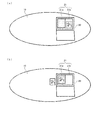
図7は、携帯型表示装置20に表示した電子文書を水平型表示装置10に表示する第1の例を示したものである。
まず、参加者は、携帯型表示装置20を水平型表示装置10に載せ、例えば、会議室内の所定の回線への接続作業を行う。すると、(a)に示すように、携帯型表示装置20の表示画面21に、共有画面に対応する領域(共有領域21a)が表示される。図では、共有領域21aを表示画面21上で一定の面積を有する領域(網掛けの領域)として示したが、例えば、フォルダのようなものであってもよい。一方、共有領域21a以外の領域は、個人用の表示領域(個人領域21b)であり、この時点では共有されていない電子文書の画像が表示されている。
次に、参加者は、個人領域21bに表示された電子文書の画像を選択し、例えばドラッグ操作により、共有領域21aに移動する。すると、水平型表示装置10及び携帯型表示装置20における表示は、(b)に示すようなものとなる。即ち、移動された電子文書が共有領域21aに表示されると共に、その電子文書がサーバ等から呼び出され、水平型表示装置10において例えば携帯型表示装置20の横に表示される。
FIG. 7 shows a first example in which an electronic document displayed on the
First, the participant places the
Next, the participant selects an image of the electronic document displayed in the
尚、この例では、電子文書の画像の上側が携帯型表示装置20の操作者にとって向こう側になるように表示した。ここで、画像の上側とは、画像に固有の属性として予め決まっている向きに配置した場合に上になる側のことをいう。人間が画像を見るときの自然な向き、例えば文字を含む画像であれば人間が文字を読める向きを、画像に固有の属性としての向きとすればよい。こうすれば、画像の上側が携帯型表示装置20の操作者にとって向こう側になるということは、水平型表示装置10において携帯型表示装置20の操作者にとって見易い向きに画像が表示されることを意味することとなる。しかしながら、電子文書の画像の表示方法としては、これ以外の表示方法を採用してもよい。例えば、携帯型表示装置20を操作する参加者が、携帯型表示装置20の表示画面21を参照しながら説明し、他の参加者が、水平型表示装置10上の表示を参照しながら説明を受ける場面も考えられる。このような場合、水平型表示装置10には、携帯型表示装置20の操作者以外の参加者にとって見易い向きに画像が表示されることが望ましい。即ち、電子文書の画像は、その上側が携帯型表示装置20の表示画面21を通常閲覧する側を向いた状態で表示するようにしてもよい。
In this example, the electronic document image is displayed so that the upper side of the image of the electronic document is away from the operator of the
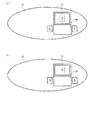
図8は、携帯型表示装置20に表示した電子文書を水平型表示装置10に表示する第2の例を示したものである。
まず、参加者は、携帯型表示装置20を水平型表示装置10に載せる。このとき、携帯型表示装置20の表示画面21には、電子文書の3ページ目が表示されているとする。すると、(a)に示すように、水平型表示装置10において、携帯型表示装置20の左側には電子文書の2ページ目が、右側には電子文書の4ページ目が表示される。
次に、参加者が、電子文書のページをめくる操作を行うと、逐次、その情報が水平型表示装置10に伝えられ、表示が更新される。例えば、(b)に示すように、携帯型表示装置20に電子文書の4ページ目が表示されたとすると、左側の画像は3ページ目に更新され、右側の画像は5ページ目に更新される。
FIG. 8 shows a second example in which an electronic document displayed on the
First, the participant places the
Next, when the participant performs an operation of turning the pages of the electronic document, the information is sequentially transmitted to the
次に、このような概略動作を実現する表示システムの構成について説明する。
尚、本実施の形態の表示システムでは、図1、5に示したように、水平型表示装置10が携帯型表示装置20のID及び自身の上での携帯型表示装置20の位置を認識する場合と、図3に示したように、携帯型表示装置20が水平型表示装置10のID及び水平型表示装置10の上での自身の位置を認識する場合とがある。
そこで、前者を第1の構成例として、後者を第2の構成例として、説明する。
Next, a configuration of a display system that realizes such a schematic operation will be described.
In the display system of the present embodiment, as shown in FIGS. 1 and 5, the
Therefore, the former will be described as a first configuration example, and the latter will be described as a second configuration example.
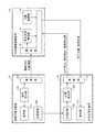
図9は、第1の構成例を示した図である。
図示するように、本実施の形態の表示システムの第1の構成例は、水平型表示装置10と、携帯型表示装置20と、携帯型表示装置20から受信した情報に応じて水平型表示装置10上の共有画面を制御する共有画面制御装置30とを含む。ここで、図1に示したように、水平型表示装置10が、赤外光を照射する赤外光光源17と、携帯型表示装置20の底面で反射した赤外光を受光する赤外カメラ18aとを備えたものである場合、携帯型表示装置20には、符号画像26aが貼付される。また、図5に示したように、水平型表示装置10が、無線通信を行う送受信機18bを備えたものである場合、携帯型表示装置20には、ワイヤレスセンサ26bが取り付けられている。尚、水平型表示装置10と共有画面制御装置30との間、及び、携帯型表示装置20と共有画面制御装置30との間は、例えばLANによって接続される。また、図では、1つの共有画面制御装置30に対して、水平型表示装置10及び携帯型表示装置20も1つずつ接続されているが、複数接続されていても構わない。
FIG. 9 is a diagram illustrating a first configuration example.
As shown in the figure, the first configuration example of the display system according to the present embodiment includes a
尚、本実施の形態では、第1の装置、第1の表示装置の一例として、水平型表示装置10を用いると共に、第1の装置の表示画面、第1の表示画面の一例として、天板11(図1、5参照)を用いた。第2の装置、第2の表示装置の一例として、携帯型表示装置20を用いると共に、第2の装置の表示画面、第2の表示画面の一例として、表示画面21(図7、8参照)を用いた。更に、表示制御装置、制御装置の一例として、共有画面制御装置30を用いた。
In the present embodiment, the
ここで、各装置の内部の機能構成について説明する。
水平型表示装置10は、画像を表示するための処理を行う表示部111と、携帯型表示装置20のID(以下、「携帯型ID」という)を検出するID検出部181と、天板11上での携帯型表示装置20の位置(以下、「携帯型位置」という)を算出する位置算出部182と、共有画面制御装置30との間で情報の送受信を行う通信部19とを備える。
表示部111は、通信部19が共有画面制御装置30から受信した表示状態に関する情報、例えば、表示位置や表示方向に関する情報に従い、天板11に投影する画像をプロジェクタ15に出力する。
ID検出部181は、赤外カメラ18aが撮像した画像又は送受信機18bが受信した情報を解析することにより、携帯型IDを検出する。
位置算出部182は、赤外カメラ18aが撮像した画像又は送受信機18bが受信した情報を解析することにより、携帯型位置を算出する。
通信部19は、自身のID、携帯型ID、携帯型位置を共有画面制御装置30に送信したり、電子文書及び表示部111における表示状態に関する情報を共有画面制御装置30から受信したりする。
Here, an internal functional configuration of each apparatus will be described.
The
The
The
The
The
携帯型表示装置20は、画像を表示するための処理を行う表示部211と、画像に対するユーザ操作を受け付ける操作受付部22と、携帯型IDを保持するID保持部261と、共有画面制御装置30との間で情報の送受信を行う通信部29とを備える。
表示部211は、ユーザ操作に応じて電子文書を表示したり、電子文書の表示内容を変更したりするための処理を行い、画像を表示画面21(図7、8参照)に表示する。
操作受付部22は、ユーザ操作を受け付けて、そのユーザ操作に基づく表示が行われるよう、そのユーザ操作に関する情報を表示部211に伝えると共に、水平型表示装置10においてそのユーザ操作に基づく表示の更新が行われるよう、そのユーザ操作に関する情報を通信部29に伝える。
ID保持部261は、符号画像26aを携帯型表示装置20の底面に貼付したり、ワイヤレスセンサ26bを携帯型表示装置20に取り付けたりすることで、実現される。即ち、本実施の形態では、第2の装置が保持する情報の一例として、符号画像26aやワイヤレスセンサ26bが保持する情報を用いた。
通信部29は、自身のIDと、操作受付部22が受け付けたユーザ操作の対象となった電子文書に関する情報(以下、「文書情報」という)とを共有画面制御装置30に送信する。ここで、文書情報とは、例えば、電子文書を一意に識別する情報(以下、「文書ID」という)や電子文書におけるページ番号である。
The
The
The
The ID holding unit 261 is realized by attaching the
The
共有画面制御装置30は、水平型表示装置10上での表示状態を管理する表示状態管理部31と、水平型表示装置10に表示する電子文書を取得する文書取得部32と、携帯型表示装置20及び水平型表示装置10との間で情報の送受信を行う通信部39とを備える。
表示状態管理部31は、どの水平型表示装置10にどの携帯型表示装置20が載っているかを把握する。また、その携帯型表示装置20がどの位置に載っているかも把握する。即ち、本実施の形態では、位置を特定する位置特定手段の一例として、表示状態管理部31のこの機能部分を設けている。更に、その携帯型表示装置20がどの方向を向いて載っているかも把握する。即ち、本実施の形態では、方向を特定する方向特定手段の一例として、表示状態管理部31のこの機能部分を設けている。更にまた、その携帯型表示装置20の表示画面21(図7、8参照)にどの電子文書の画像が表示されているか、及び、その画像がどのように変更されたかも把握する。即ち、本実施の形態では、画像を特定する画像特定手段、画像の変更を認識する認識手段の一例として、表示状態管理部31のこの機能部分を設けている。
The shared
The display
文書取得部32は、水平型表示装置10に新たに表示すべき電子文書又はページが生じた場合に、その電子文書又はページを、文書サーバ(図示せず)、携帯型表示装置20、事前に電子文書を格納しておいた共有画面制御装置30内のメモリ(図示せず)等から読み出す。
通信部39は、水平型表示装置10から水平型ID、携帯型ID、携帯型位置を受信し、携帯型表示装置20から携帯型ID及び文書情報を受信する。また、水平型表示装置10に対して電子文書及び表示状態に関する情報を送信する。即ち、本実施の形態では、表示を制御する制御手段の一例として、通信部39を設けている。
When a new electronic document or page to be displayed on the
The
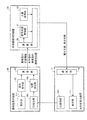
図10は、第2の構成例を示した図である。
図示するように、本実施の形態の表示システムの第2の構成例も、水平型表示装置10と、携帯型表示装置20と、携帯型表示装置20から受信した情報に応じて水平型表示装置10上の共有画面を制御する共有画面制御装置30とを含む。ここで、図3に示したように、携帯型表示装置20が、赤外光を照射する赤外光光源27と、水平型表示装置10の天板11で反射した赤外光を受光する赤外カメラ28とを備えたものである場合、水平型表示装置10には、符号画像16が貼付される。尚、この構成例においても、水平型表示装置10と共有画面制御装置30との間、及び、携帯型表示装置20と共有画面制御装置30との間は、例えばLANによって接続される。また、図では、1つの共有画面制御装置30に対して、水平型表示装置10及び携帯型表示装置20も1つずつ接続されているが、複数接続されていても構わない。
FIG. 10 is a diagram illustrating a second configuration example.
As shown in the figure, the second configuration example of the display system according to the present embodiment also includes a
尚、本実施の形態では、第1の装置、第1の表示装置の一例として、水平型表示装置10を用いると共に、第1の装置の表示画面、第1の表示画面の一例として、天板11(図3参照)を用いた。また、第2の装置、第2の表示装置の一例として、携帯型表示装置20を用いると共に、第2の装置の表示画面、第2の表示画面の一例として、表示画面21(図7、8参照)を用いた。更に、表示制御装置、制御装置の一例として、共有画面制御装置30を用いた。
In the present embodiment, the
ここで、各装置の内部の機能構成について説明する。
水平型表示装置10は、画像を表示するための処理を行う表示部111と、水平型表示装置10のID(以下、「水平型ID」という)を保持するID保持部161と、共有画面制御装置30との間で情報の送受信を行う通信部19とを備える。
表示部111は、通信部19が共有画面制御装置30から受信した表示状態に関する情報、例えば、表示位置や表示方向に関する情報に従い、天板11に投影する画像をプロジェクタ15に出力する。
ID保持部161は、例えば符号画像16を天板11の表面に貼付することで、実現される。即ち、本実施の形態では、第1の装置が保持する情報の一例として、符号画像16が保持する情報を用いた。
通信部19は、電子文書及び表示部111における表示状態に関する情報を共有画面制御装置30から受信する。
Here, an internal functional configuration of each apparatus will be described.
The
The
The
The
携帯型表示装置20は、画像を表示するための処理を行う表示部211と、画像に対するユーザ操作を受け付ける操作受付部22と、水平型IDを検出するID検出部281と、水平型表示装置10上での自身の位置である携帯型位置を検出する位置検出部282と、共有画面制御装置30との間で情報の送受信を行う通信部29とを備える。
表示部211は、ユーザ操作に応じて電子文書を表示したり、電子文書の表示内容を変更したりするための処理を行い、画像を表示画面21(図7、8参照)に表示する。
操作受付部22は、ユーザ操作を受け付けて、そのユーザ操作に基づく表示が行われるよう、そのユーザ操作に関する情報を表示部211に伝えると共に、水平型表示装置10においてそのユーザ操作に基づく表示の更新が行われるよう、そのユーザ操作に関する情報を通信部29に伝える。
ID検出部281は、赤外カメラ28が撮像した画像を解析することにより、水平型IDを検出する。
位置検出部282は、赤外カメラ28が撮像した画像を解析することにより、携帯型位置を算出する。
通信部29は、水平型ID、自身のID、携帯型位置、更には、操作受付部22が受け付けたユーザ操作の対象となった電子文書に関する文書情報を共有画面制御装置30に送信する。
The
The
The
The
The
The
共有画面制御装置30は、水平型表示装置10上での表示状態を管理する表示状態管理部31と、水平型表示装置10に表示する電子文書を取得する文書取得部32と、携帯型表示装置20及び水平型表示装置10との間で情報の送受信を行う通信部39とを備える。
表示状態管理部31は、どの水平型表示装置10にどの携帯型表示装置20が載っているかを把握する。また、その携帯型表示装置20がどの位置に載っているかも把握する。即ち、本実施の形態では、位置を特定する位置特定手段の一例として、表示状態管理部31のこの機能部分を設けている。更に、その携帯型表示装置20がどの方向を向いて載っているかも把握する。即ち、本実施の形態では、方向を特定する方向特定手段の一例として、表示状態管理部31のこの機能部分を設けている。更にまた、その携帯型表示装置20の表示画面21(図7、8参照)にどの電子文書の画像が表示されているか、及び、その画像がどのように変更されたかも把握する。即ち、本実施の形態では、画像を特定する画像特定手段、画像の変更を認識する認識手段の一例として、表示状態管理部31のこの機能部分を設けている。
The shared
The display
文書取得部32は、水平型表示装置10に新たに表示すべき電子文書又はページが生じた場合に、その電子文書又はページを、文書サーバ(図示せず)、携帯型表示装置20、事前に電子文書を格納しておいた共有画面制御装置30内のメモリ(図示せず)等から読み出す。
通信部39は、携帯型表示装置20から水平型ID、携帯型ID、携帯型位置、文書情報を受信する。また、水平型表示装置10に対して電子文書及び表示状態に関する情報を送信する。即ち、本実施の形態では、表示を制御する制御手段の一例として、通信部39を設けている。
When a new electronic document or page to be displayed on the
The
尚、図9及び図10のシステム構成では、水平型表示装置10とは別に共有画面制御装置30を設けたが、共有画面制御装置30は、水平型表示装置10と一体に設けてもよい。そして、このような構成を採用した場合は、管理情報において、水平型IDは必ずしも管理しなくてよい。
9 and 10, the shared
次に、本実施の形態の表示システムにおける動作を説明する。
図9では、まず、水平型表示装置10において、ID検出部181が携帯型IDを検出し、位置算出部182が携帯型位置を算出して、通信部19が水平型IDと共に、これらの情報を共有画面制御装置30に送信する。また、携帯型表示装置20において、操作受付部22がユーザ操作を受け付け、通信部29が携帯型IDと共に、ユーザ操作の対象となった電子文書の文書情報を共有画面制御装置30に送信する。
図10では、携帯型表示装置20において、ID検出部281が水平型IDを、位置検出部282が携帯型位置を検出して、通信部29が携帯型IDと共に、これらの情報を共有画面制御装置30に送信する。また同様に、携帯型表示装置20において、操作受付部22がユーザ操作を受け付け、通信部29が携帯型IDと共に、ユーザ操作の対象となった電子文書の文書情報を共有画面制御装置30に送信する。
Next, the operation in the display system of this embodiment will be described.
In FIG. 9, first, in the
In FIG. 10, in the
これにより、共有画面制御装置30の動作が開始する。尚、ここでは、図7、8の表示を実現するための動作を分けて説明する。
図11は、図7の表示を実現するための共有画面制御装置30の動作を示したフローチャートである。
共有画面制御装置30では、まず、通信部39が、水平型IDと携帯型IDと携帯型位置とからなる情報を受信したか、携帯型IDと文書IDとからなる情報を受信したかを判定する(ステップ301)。
Thereby, the operation of the shared
FIG. 11 is a flowchart showing the operation of the shared
In the shared
水平型IDと携帯型IDと携帯型位置とからなる情報を受信したと判定された場合、受信した情報は、表示状態管理部31に渡される。尚、図9のシステム構成であれば、この情報は水平型表示装置10から受信したものであり、図10のシステム構成であれば、この情報は携帯型表示装置20から受信したものである。そして、表示状態管理部31は、水平型IDと携帯型IDと携帯型位置との対応に変化があったかどうかを判定する(ステップ302)。変化がなければ、処理を終了するが、変化があれば、受信した水平型IDと携帯型IDと携帯型位置との対応を登録する(ステップ303)。
When it is determined that information including the horizontal ID, the portable ID, and the portable position is received, the received information is passed to the display
携帯型IDと文書IDとからなる情報を受信したと判定された場合も、受信した情報は、表示状態管理部31に渡される。尚、この場合、図9のシステム構成であっても、図10のシステム構成であっても、この情報は、携帯型表示装置20から受信したものである。そして、表示状態管理部31は、携帯型IDと文書IDとの対応に変化があったかどうかを判定する(ステップ304)。変化がなければ、処理を終了するが、変化があれば、受信した携帯型IDと文書IDの対応を登録する(ステップ305)。
Even when it is determined that the information including the portable ID and the document ID is received, the received information is passed to the display
ステップ302で変化があったと判定された場合はステップ303の処理に引き続き、ステップ304で変化があったと判定された場合はステップ305の処理に引き続き、表示状態管理部31が、水平型表示装置10上での電子文書の表示位置及び表示方向を算出する(ステップ306)。例えば、図7では、ステップ301で受信した携帯型位置の横の位置を表示位置として算出する。
If it is determined that there has been a change in step 302, the display
そして、文書取得部32が表示対象の電子文書を読み出す(ステップ307)。ここで、表示対象の電子文書は、携帯型表示装置20におけるユーザ操作の対象となった電子文書と必ずしも同じものでなくてよい。例えば、ユーザ操作の対象となった電子文書に予め関連付けられた他の電子文書を表示対象の電子文書として選択するようにしてもよい。この場合、予め関連付けられた他の電子文書の画像は、所定の関係を有する画像の一例である。また、このように所定の関係を有する画像が選択された場合において、ステップ306で算出される表示位置及び表示方向は、この所定の関係に応じたものとしてもよい。
Then, the
その後、通信部39が、ステップ306で算出した表示位置及び表示方向の情報と、ステップ307で読み出した電子文書とを水平型表示装置10に送信する(ステップ308)。
これにより、水平型表示装置10では、送信された電子文書の画像が、送信された表示位置に、送信された表示方向で表示されることとなる。
Thereafter, the
Thereby, in the
ここで、図11の処理において表示状態管理部31が参照及び更新を行う管理情報について述べる。尚、管理情報は、表示状態管理部31が参照可能なメモリ(図示せず)に記憶しておくとよい。
この管理情報の説明の前に、まず、水平型表示装置10の画面上の座標について説明しておく。図12(a)に、画面上に設定する座標の例を示す。ここでは、画面を長方形とし、中心点を原点としている。そして、長手方向にX軸を、短手方向にY軸をとっている。
画面上には、携帯型表示装置20を載せた位置が、A1、B1、C1、D1を頂点とする四角形、及び、A2、B2、C2、D2を頂点とする四角形で示されている。但し、これはあくまで一例であり、例えば、短い間隔で格子状に配置された点のうち、携帯型表示装置20を載せた領域内に存在する点を管理するようなものであってもよい。
Here, management information that the display
Before describing the management information, first, the coordinates on the screen of the
On the screen, the position on which the
携帯型表示装置20がこのように置かれた場合の管理情報の内容を図12(b)に示す。但し、(a)は水平型ID「P001」の水平型表示装置10に携帯型表示装置20の置かれた状態を示すものとし、この水平型表示装置10とは別に水平型ID「P002」の水平型表示装置10も管理されているものとする。
尚、(b)の携帯型位置欄における座標については、(a)で点に付した記号の後ろに「x」を付加することによりその点のX座標を表し、(a)で点に付した記号の後ろに「y」を付加することによりその点のY座標を表すものとする。また、この場合、携帯型表示装置20は矩形で近似し、4頂点の座標でその置かれた範囲を表すようにしているが、画面上でいずれの向きに置かれているかを示すために、左上点、右上点、左下点の3点の座標を記憶している。更に、管理情報には、携帯型表示装置20に表示された電子文書のうちユーザ操作の対象となった電子文書の文書IDも記憶されている。
FIG. 12B shows the contents of the management information when the
Note that the coordinates in the portable position field of (b) represent the X coordinate of the point by adding “x” after the symbol attached to the point in (a), and attached to the point in (a). It is assumed that the Y coordinate of the point is represented by adding “y” after the symbol. Further, in this case, the
図11のステップ302では、図12(b)の管理情報において、水平型IDと携帯型IDと携帯型位置との対応関係に変化があったかどうかが判定される。そして、変化があったと判定された場合は、ステップ303において、登録済の対応関係が新たな対応関係に変更される。また、図11のステップ304では、図12(b)の管理情報において、携帯型IDと文書IDとの対応関係に変化があったかどうかが判定される。そして、変化があったと判定された場合は、ステップ305において、登録済の対応関係が新たな対応関係に変更される。 In step 302 of FIG. 11, it is determined whether or not the correspondence relationship between the horizontal ID, the portable ID, and the portable position has changed in the management information of FIG. If it is determined that there is a change, the registered correspondence is changed to a new correspondence in step 303. Further, in step 304 in FIG. 11, it is determined whether or not the correspondence relationship between the portable ID and the document ID has changed in the management information in FIG. If it is determined that there has been a change, then in step 305, the registered correspondence is changed to a new correspondence.
図13は、図8の表示を実現するための共有画面制御装置30の動作を示したフローチャートである。
共有画面制御装置30では、まず、通信部39が、水平型IDと携帯型IDと携帯型位置とからなる情報を受信したか、携帯型IDと文書IDとページ番号とからなる情報を受信したかを判定する(ステップ351)。
FIG. 13 is a flowchart showing the operation of the shared
In the shared
水平型IDと携帯型IDと携帯型位置とからなる情報を受信したと判定された場合、受信した情報は、表示状態管理部31に渡される。尚、図9のシステム構成であれば、この情報は水平型表示装置10から受信したものであり、図10のシステム構成であれば、この情報は携帯型表示装置20から受信したものである。そして、表示状態管理部31は、水平型IDと携帯型IDと携帯型位置との対応に変化があったかどうかを判定する(ステップ352)。変化がなければ、処理を終了するが、変化があれば、受信した水平型IDと携帯型IDと携帯型位置との対応を登録する(ステップ353)。
When it is determined that information including the horizontal ID, the portable ID, and the portable position is received, the received information is passed to the display
携帯型IDと文書IDとページ番号とからなる情報を受信したと判定された場合も、受信した情報は、表示状態管理部31に渡される。尚、この場合、図9のシステム構成であっても、図10のシステム構成であっても、この情報は、携帯型表示装置20から受信したものである。そして、表示状態管理部31は、携帯型IDと文書IDとページ番号との対応に変化があったかどうかを判定する(ステップ354)。変化がなければ、処理を終了するが、変化があれば、受信した携帯型IDと文書IDとページ番号との対応を登録する(ステップ355)。
Even when it is determined that information including a portable ID, a document ID, and a page number has been received, the received information is passed to the display
ステップ352で変化があったと判定された場合はステップ353の処理に引き続き、ステップ354で変化があったと判定された場合はステップ355の処理に引き続き、表示状態管理部31が、携帯型表示装置20に表示された電子文書のページの前後のページの水平型表示装置10上での表示位置及び表示方向を算出する(ステップ356)。例えば、図8では、ステップ351で受信した携帯型位置の左右の位置を表示位置として算出する。
If it is determined in step 352 that there is a change, the display
そして、文書取得部32が、携帯型表示装置20に表示されたページの前後のページを表示対象のページとして読み出す(ステップ357)。但し、表示対象のページは、必ずしも前後のページでなくてよい。例えば、携帯型表示装置20に表示されたページに予め関連付けられた他のページを表示対象のページとして選択するようにしてもよい。或いは、水平型表示装置10への表示制御は、ページ単位で行わなくてもよい。例えば、あるフォルダ配下の画像データのうち、携帯型表示装置20に表示された画像データよりも時間順で1つ前に作成した画像データと1つ後に作成した画像データとを表示対象として読み出してもよい。即ち、本実施の形態では、所定の順序関係において先及び後となる2つの画像の一例として、前ページの画像及び次ページの画像を用いた。また、第2の装置の位置を中心として対称な2つの位置の一例として、携帯型表示装置20の左側の位置及び右側の位置を用いた。
Then, the
その後、通信部39が、ステップ356で算出した表示位置及び表示方向の情報と、ステップ357で読み出したページとを水平型表示装置10に送信する(ステップ358)。
これにより、水平型表示装置10では、送信されたページが、送信された表示位置に、送信された表示方向で表示されることになる。
Thereafter, the
Thereby, in the
ここで、図13の処理において表示状態管理部31が参照及び更新を行う管理情報について述べる。尚、管理情報は、表示状態管理部31が参照可能なメモリ(図示せず)に記憶しておくとよい。
この管理情報でも、図12(a)を参照して説明したのと同様に座標を表現し、携帯型表示装置20が図12(a)のように置かれているものとする。
携帯型表示装置20がこのように置かれた場合の管理情報の内容を図14に示す。但し、ここでは、図12(a)に示す水平型ID「P001」の水平型表示装置10とは別に水平型ID「P002」の水平型表示装置10も管理されているものとする。また、管理情報には、携帯型表示装置20に表示された電子文書のうちユーザ操作の対象となった電子文書の文書ID及びページも記憶されていている。
Here, management information that the display
In this management information, it is assumed that coordinates are expressed in the same manner as described with reference to FIG. 12A, and the
FIG. 14 shows the contents of the management information when the
図13のステップ352では、図14の管理情報において、水平型IDと携帯型IDと携帯型位置との対応関係に変化があったかどうかが判定される。そして、変化があったと判定された場合は、ステップ353において、登録済の対応関係が新たな対応関係に変更される。また、図13のステップ354では、図14の管理情報において、携帯型IDと文書IDとページ番号との対応関係に変化があったかどうかが判定される。そして、変化があったと判定された場合は、ステップ355において、登録済の対応関係が新たな対応関係に変更される。 In step 352 of FIG. 13, it is determined whether or not there is a change in the correspondence between the horizontal ID, the portable ID, and the portable position in the management information of FIG. If it is determined that there has been a change, in step 353, the registered correspondence is changed to a new correspondence. In step 354 of FIG. 13, it is determined whether or not the correspondence relationship between the portable ID, the document ID, and the page number has changed in the management information of FIG. If it is determined that there has been a change, then in step 355, the registered correspondence is changed to a new correspondence.
最後に、本実施の形態をコンピュータ90にて実現するものとして、このコンピュータ90のハードウェア構成について説明する。
図15は、コンピュータ90のハードウェア構成を示した図である。
図示するように、コンピュータ90は、演算手段であるCPU(Central Processing Unit)91と、記憶手段であるメインメモリ92及び磁気ディスク装置(HDD:Hard Disk Drive)93とを備える。ここで、CPU91は、OS(Operating System)やアプリケーション等の各種ソフトウェアを実行し、上述した各機能を実現する。また、メインメモリ92は、各種ソフトウェアやその実行に用いるデータ等を記憶する記憶領域であり、磁気ディスク装置93は、各種ソフトウェアに対する入力データや各種ソフトウェアからの出力データ等を記憶する記憶領域である。
更に、コンピュータ90は、外部との通信を行うための通信I/F94と、ビデオメモリやディスプレイ等からなる表示機構95と、キーボードやマウス等の入力デバイス96とを備える。
Finally, assuming that the present embodiment is realized by the computer 90, the hardware configuration of the computer 90 will be described.
FIG. 15 is a diagram illustrating a hardware configuration of the computer 90.
As shown in the figure, the computer 90 includes a CPU (Central Processing Unit) 91 as a calculation means, a
Further, the computer 90 includes a communication I /
尚、本実施の形態を実現するプログラムは、通信手段により提供することはもちろん、CD−ROM等の記録媒体に格納して提供することも可能である。 The program for realizing the present embodiment can be provided not only by communication means but also by storing it in a recording medium such as a CD-ROM.
10…水平型表示装置、11…天板、13…投影ユニット、15…プロジェクタ、20…携帯型表示装置
DESCRIPTION OF
Claims (10)
前記第2の装置の表示画面上の共有領域に画像が表示された場合に、当該共有領域に表示された画像に応じた所定画像が前記第1の装置の表示画面に表示されるように制御する制御手段と、
前記第2の装置が前記共有領域における画像の表示を更新する操作を受け付けた場合に、当該更新する操作に応じて、前記第1の装置の表示画面に表示される前記所定画像の表示を更新する更新手段と
を備えたことを特徴とする表示制御装置。 Connection means for connecting a first device having a display screen and a second device having a display screen;
When an image is displayed in the shared area on the display screen of the second device, control is performed so that a predetermined image corresponding to the image displayed in the shared area is displayed on the display screen of the first device. Control means to
When the second device receives an operation for updating the display of the image in the shared area, the display of the predetermined image displayed on the display screen of the first device is updated according to the update operation. A display control apparatus comprising: an updating unit configured to perform updating.
前記制御手段は、前記位置特定手段により特定された前記第2の装置の位置に応じた前記第1の装置の表示画面上の所定位置に前記所定画像が表示されるように制御することを特徴とする請求項1に記載の表示制御装置。 A position specifying means for specifying the position of the second device on the display screen of the first device;
The control means controls the predetermined image to be displayed at a predetermined position on the display screen of the first device according to the position of the second device specified by the position specifying means. The display control apparatus according to claim 1.
前記所定位置は、前記位置特定手段により特定された前記第2の装置の位置との間に前記所定の関係に応じた関係を有する位置であることを特徴とする請求項2に記載の表示制御装置。 The predetermined image is an image having a predetermined relationship with an image displayed in the shared area,
The display control according to claim 2, wherein the predetermined position is a position having a relationship corresponding to the predetermined relationship with the position of the second device specified by the position specifying unit. apparatus.
前記所定位置は、前記位置特定手段により特定された前記第2の装置の位置を中心として対称な2つの位置であることを特徴とする請求項2又は請求項3に記載の表示制御装置。 The predetermined images are two images that are first and second in a predetermined order with respect to the image displayed in the shared area,
The display control apparatus according to claim 2, wherein the predetermined position is two positions symmetrical about the position of the second device specified by the position specifying unit.
前記制御手段は、前記方向特定手段により特定された前記第2の装置の方向に応じて、前記所定画像が表示されるように制御することを特徴とする請求項1乃至請求項6の何れかに記載の表示制御装置。 Direction specifying means for specifying the direction of the second device on the display screen of the first device;
7. The control unit according to claim 1, wherein the control unit controls the predetermined image to be displayed according to the direction of the second device specified by the direction specifying unit. The display control apparatus according to 1.
第2の表示画面に画像を表示する第2の表示手段と、
前記第1の表示手段と前記第2の表示手段とを接続する接続手段と、
前記第2の表示画面上の共有領域に画像が表示された場合に、当該共有領域に表示された画像に応じた所定画像が前記第1の表示画面に表示されるように制御する制御手段と、
前記第2の表示手段が前記共有領域における画像の表示を更新する操作を受け付けた場合に、当該更新する操作に応じて、前記第1の表示画面に表示される前記所定画像の表示を更新する更新手段と
を備えたことを特徴とする表示システム。 First display means for displaying an image on a first display screen;
Second display means for displaying an image on a second display screen;
Connection means for connecting the first display means and the second display means;
Control means for controlling so that a predetermined image corresponding to the image displayed in the shared area is displayed on the first display screen when an image is displayed in the shared area on the second display screen; ,
When the second display unit accepts an operation for updating the display of the image in the shared area, the display of the predetermined image displayed on the first display screen is updated according to the update operation. A display system comprising update means.
表示画面を有する第1の装置と表示画面を有する第2の装置とを接続する機能と、
前記第2の装置の表示画面上の共有領域に画像が表示された場合に、当該共有領域に表示された画像に応じた所定画像が前記第1の装置の表示画面に表示されるように制御する機能と、
前記第2の装置が前記共有領域における画像の表示を更新する操作を受け付けた場合に、当該更新する操作に応じて、前記第1の装置の表示画面に表示される前記所定画像の表示を更新する機能と
を実現させるためのプログラム。 On the computer,
A function of connecting a first device having a display screen and a second device having a display screen;
When an image is displayed in the shared area on the display screen of the second device, control is performed so that a predetermined image corresponding to the image displayed in the shared area is displayed on the display screen of the first device. Function to
When the second device receives an operation for updating the display of the image in the shared area, the display of the predetermined image displayed on the display screen of the first device is updated according to the update operation. Program to realize the function to perform.
Priority Applications (1)
| Application Number | Priority Date | Filing Date | Title |
|---|---|---|---|
| JP2012178737A JP2012252356A (en) | 2012-08-10 | 2012-08-10 | Display control device, display system and program |
Applications Claiming Priority (1)
| Application Number | Priority Date | Filing Date | Title |
|---|---|---|---|
| JP2012178737A JP2012252356A (en) | 2012-08-10 | 2012-08-10 | Display control device, display system and program |
Related Parent Applications (1)
| Application Number | Title | Priority Date | Filing Date |
|---|---|---|---|
| JP2007086656A Division JP2008242367A (en) | 2007-03-29 | 2007-03-29 | Display-control device, display device, display system, and program |
Publications (1)
| Publication Number | Publication Date |
|---|---|
| JP2012252356A true JP2012252356A (en) | 2012-12-20 |
Family
ID=47525161
Family Applications (1)
| Application Number | Title | Priority Date | Filing Date |
|---|---|---|---|
| JP2012178737A Pending JP2012252356A (en) | 2012-08-10 | 2012-08-10 | Display control device, display system and program |
Country Status (1)
| Country | Link |
|---|---|
| JP (1) | JP2012252356A (en) |
Cited By (1)
| Publication number | Priority date | Publication date | Assignee | Title |
|---|---|---|---|---|
| CN111427528A (en) * | 2020-03-20 | 2020-07-17 | 北京字节跳动网络技术有限公司 | Display method and device and electronic equipment |
Citations (6)
| Publication number | Priority date | Publication date | Assignee | Title |
|---|---|---|---|---|
| JPH06332819A (en) * | 1993-05-27 | 1994-12-02 | Hitachi Ltd | Conference screen display control system |
| JP2002204239A (en) * | 2000-10-24 | 2002-07-19 | Sony Corp | Device and method for information processing, electronic equipment, information processing system, and recording medium |
| JP2004164069A (en) * | 2002-11-11 | 2004-06-10 | Nippon Telegr & Teleph Corp <Ntt> | Information control system, information control method, program for the same, recording medium recording that program |
| JP2005031448A (en) * | 2003-07-04 | 2005-02-03 | Fuji Xerox Co Ltd | Information display system and information display method |
| JP2005100050A (en) * | 2003-09-24 | 2005-04-14 | Fuji Xerox Co Ltd | Information display system and method |
| JP2008243125A (en) * | 2007-03-29 | 2008-10-09 | Fuji Xerox Co Ltd | Display control apparatus, medium managing device, and program |
-
2012
- 2012-08-10 JP JP2012178737A patent/JP2012252356A/en active Pending
Patent Citations (6)
| Publication number | Priority date | Publication date | Assignee | Title |
|---|---|---|---|---|
| JPH06332819A (en) * | 1993-05-27 | 1994-12-02 | Hitachi Ltd | Conference screen display control system |
| JP2002204239A (en) * | 2000-10-24 | 2002-07-19 | Sony Corp | Device and method for information processing, electronic equipment, information processing system, and recording medium |
| JP2004164069A (en) * | 2002-11-11 | 2004-06-10 | Nippon Telegr & Teleph Corp <Ntt> | Information control system, information control method, program for the same, recording medium recording that program |
| JP2005031448A (en) * | 2003-07-04 | 2005-02-03 | Fuji Xerox Co Ltd | Information display system and information display method |
| JP2005100050A (en) * | 2003-09-24 | 2005-04-14 | Fuji Xerox Co Ltd | Information display system and method |
| JP2008243125A (en) * | 2007-03-29 | 2008-10-09 | Fuji Xerox Co Ltd | Display control apparatus, medium managing device, and program |
Non-Patent Citations (3)
| Title |
|---|
| CSNG200000192010; 石崎健史、外2名: '「リアルタイムCSCWシステムにおけるアプリケーション間データ交換方式」' 情報処理学会研究報告 第93巻第12号, 19930129, 第73頁〜第79頁, 社団法人情報処理学会 * |
| JPN6012059984; 石崎健史、外2名: '「リアルタイムCSCWシステムにおけるアプリケーション間データ交換方式」' 情報処理学会研究報告 第93巻第12号, 19930129, 第73頁〜第79頁, 社団法人情報処理学会 * |
| JPN6012059987; 塩澤秀和、外2名: '「背景と奥行きを利用した協調作業空間」' 情報処理学会論文誌 第40巻第11号, 19991115, 第3823頁〜第3833頁, 社団法人情報処理学会 * |
Cited By (2)
| Publication number | Priority date | Publication date | Assignee | Title |
|---|---|---|---|---|
| CN111427528A (en) * | 2020-03-20 | 2020-07-17 | 北京字节跳动网络技术有限公司 | Display method and device and electronic equipment |
| CN111427528B (en) * | 2020-03-20 | 2023-07-25 | 北京字节跳动网络技术有限公司 | Display method and device and electronic equipment |
Similar Documents
| Publication | Publication Date | Title |
|---|---|---|
| JP2008242367A (en) | Display-control device, display device, display system, and program | |
| US10241565B2 (en) | Apparatus, system, and method of controlling display, and recording medium | |
| TWI559174B (en) | Gesture based manipulation of three-dimensional images | |
| US20180104816A1 (en) | Robot device and non-transitory computer readable medium | |
| CN103814343A (en) | Manipulating and displaying image on wearable computing system | |
| JP5598232B2 (en) | Information processing apparatus, information processing system, and information processing method | |
| JP6417787B2 (en) | Display device, transmission system, and transmission method | |
| KR20180123217A (en) | Method and apparatus for providing a user interface with a computerized system and interacting with the virtual environment | |
| JP2006178205A (en) | Digital platform device | |
| JP6300113B2 (en) | Information display system and information display terminal | |
| WO2015159602A1 (en) | Information providing device | |
| JPWO2019069575A1 (en) | Information processing equipment, information processing methods and programs | |
| TWI582676B (en) | Displaying an object indicator | |
| JP4957327B2 (en) | Display control device | |
| JP5657471B2 (en) | Digital platform device | |
| JP2017175580A (en) | Information display system and information providing terminal | |
| JP2017175579A (en) | Information display system and information providing terminal | |
| US10409143B2 (en) | Tracking a handheld device on surfaces with optical patterns | |
| US20150253932A1 (en) | Information processing apparatus, information processing system and information processing method | |
| JP3828474B2 (en) | Position detection input / output device | |
| JP2012252356A (en) | Display control device, display system and program | |
| WO2015159550A1 (en) | Information processing system, control method, and program recording medium | |
| CN107148604A (en) | Electronic installation and feedback offer method | |
| CN107003717A (en) | The received touch input of conversion | |
| WO2018008096A1 (en) | Information display device and program |
Legal Events
| Date | Code | Title | Description |
|---|---|---|---|
| A871 | Explanation of circumstances concerning accelerated examination |
Free format text: JAPANESE INTERMEDIATE CODE: A871 Effective date: 20121004 |
|
| A975 | Report on accelerated examination |
Free format text: JAPANESE INTERMEDIATE CODE: A971005 Effective date: 20121101 |
|
| A131 | Notification of reasons for refusal |
Free format text: JAPANESE INTERMEDIATE CODE: A131 Effective date: 20121120 |
|
| A521 | Request for written amendment filed |
Free format text: JAPANESE INTERMEDIATE CODE: A523 Effective date: 20130121 |
|
| A02 | Decision of refusal |
Free format text: JAPANESE INTERMEDIATE CODE: A02 Effective date: 20130212 |