JP4111165B2 - Portable electronic device, wireless communication system and wireless connection control method thereof - Google Patents
Portable electronic device, wireless communication system and wireless connection control method thereof Download PDFInfo
- Publication number
- JP4111165B2 JP4111165B2 JP2004138910A JP2004138910A JP4111165B2 JP 4111165 B2 JP4111165 B2 JP 4111165B2 JP 2004138910 A JP2004138910 A JP 2004138910A JP 2004138910 A JP2004138910 A JP 2004138910A JP 4111165 B2 JP4111165 B2 JP 4111165B2
- Authority
- JP
- Japan
- Prior art keywords
- electronic device
- connection
- wireless communication
- portable electronic
- information
- Prior art date
- Legal status (The legal status is an assumption and is not a legal conclusion. Google has not performed a legal analysis and makes no representation as to the accuracy of the status listed.)
- Expired - Fee Related
Links
Images


Classifications
-
- H—ELECTRICITY
- H04—ELECTRIC COMMUNICATION TECHNIQUE
- H04W—WIRELESS COMMUNICATION NETWORKS
- H04W76/00—Connection management
- H04W76/10—Connection setup
- H04W76/14—Direct-mode setup
-
- H—ELECTRICITY
- H04—ELECTRIC COMMUNICATION TECHNIQUE
- H04W—WIRELESS COMMUNICATION NETWORKS
- H04W4/00—Services specially adapted for wireless communication networks; Facilities therefor
- H04W4/02—Services making use of location information
- H04W4/029—Location-based management or tracking services
-
- H—ELECTRICITY
- H04—ELECTRIC COMMUNICATION TECHNIQUE
- H04W—WIRELESS COMMUNICATION NETWORKS
- H04W4/00—Services specially adapted for wireless communication networks; Facilities therefor
- H04W4/02—Services making use of location information
-
- H—ELECTRICITY
- H04—ELECTRIC COMMUNICATION TECHNIQUE
- H04W—WIRELESS COMMUNICATION NETWORKS
- H04W64/00—Locating users or terminals or network equipment for network management purposes, e.g. mobility management
Description
本発明は、携帯電子機器、無線通信システム及びその無線接続制御方法に関する。 The present invention relates to a portable electronic device , a wireless communication system, and a wireless connection control method thereof.
近年、携帯電話機やPDA(Personal Digital Assistant)等が急速に普及してきた。その結果、各ユーザは、複数のこれらの機器の間において、情報を交換する機会が多くなってきている。 In recent years, mobile phones, PDAs (Personal Digital Assistants) and the like have been rapidly spread. As a result, each user has more opportunities to exchange information among a plurality of these devices.
従来、このような情報交換を行う場合、機器をクレードルやケーブルを介して相互に接続したり、赤外線送受信部を相互に対面させて送受信させるようにしていた。 Conventionally, when such information exchange is performed, devices are connected to each other via a cradle or a cable, or infrared transmission / reception units face each other for transmission / reception.
しかし、有線の接続は、煩雑であるばかりでなく、それぞれの機種にあったコネクタを用意しなければならず、不便であった。また、赤外線を利用する場合、赤外線の伝送路をユーザが不用意に通過する等して、遮ってしまうと、通信が遮断されてしまうという問題があった。 However, the wired connection is not only complicated, but a connector suitable for each model must be prepared, which is inconvenient. In addition, when using infrared rays, there is a problem that communication is interrupted if the user interrupts the infrared transmission path by inadvertently passing it.
そこで、IEEE(Institute of Electrical and Electronics Engineers)802.11通信規格やブルートゥース(Bluetooth(登録商標))通信規格に代表される無線通信機能を備える電子機器が普及してきている。 Therefore, electronic devices having wireless communication functions represented by IEEE (Institute of Electrical and Electronics Engineers) 802.11 communication standard and Bluetooth (Bluetooth (registered trademark)) communication standard have become widespread.
しかしながら、無線で通信を行う場合、通信を行う機器のアドレスをユーザが入力しなければならず、通常、ユーザは、各機器のアドレスを記憶しているわけではないので、アドレス表などを予め作成しておき、それを参照してアドレスを手動入力するようにしている。その結果、操作性が悪く、不便であった。このため、例えば、ユーザが持っているPDAと、ユーザの目の前に設置されている機器との間で情報を交換するような場合にも、相手側の機器のアドレスを入力しなければならず、迅速な情報の交換が困難であった。 However, when communicating wirelessly, the user must input the address of the device that performs the communication. Normally, the user does not always store the address of each device, so an address table or the like is created in advance. A reference is made to manually input the address. As a result, the operability was poor and inconvenient. For this reason, for example, even when information is exchanged between a PDA held by the user and a device installed in front of the user, the address of the partner device must be entered. Therefore, it was difficult to exchange information quickly.
これらの無線通信機能を有する機器間では、プライバシーに関する情報など、機密性が要求される情報も送受信されることから、そのような情報が第三者により盗聴、改竄されること、或いは、不正なネットワークへの侵入を防止するためのセキュリティ対策が必要になる。 Information that requires confidentiality, such as privacy-related information, is also transmitted and received between devices having these wireless communication functions. Such information can be intercepted or tampered with by a third party, or illegal. Security measures are required to prevent intrusion into the network.
例えば、IEEE802.11通信規格では、ユーザは、WEP(Wired Equivalent Privacy)キーと呼ばれる秘密鍵を、通信を行う機器に予め登録し、そのWEPキーを用いた暗号化通信を行わせることにより通信のセキュリティを確保している。また、ディジタル証明書を予め発行し、通信の開始時に、証明書を用いて通信相手の機器の認証を行わせることにより、正当な通信相手であるか否かを判定させ、セキュリティを確保することも行われている。 For example, in the IEEE 802.11 communication standard, a user registers a secret key called a WEP (Wired Equivalent Privacy) key in advance in a device that performs communication, and performs communication by performing encrypted communication using the WEP key. Security is ensured. In addition, by issuing a digital certificate in advance and using the certificate to authenticate the communication partner device at the start of communication, it is possible to determine whether or not the communication partner is a legitimate communication partner, thereby ensuring security. Has also been done.
ところで、セキュリティ確保のために、常に、このような鍵情報の登録や証明書の発行を予め行うとすると、無線通信の接続対象の切り替えに迅速に対応することができない。例えば、2台の携帯機器を一時的に無線で接続し、あるファイルの転送を行うことや、ディジタルカメラを店舗に設置されているプリンタに一時的に無線で接続し、撮影した写真の印刷を行うこと、或いは、ビデオカメラと携帯電話を一時的に無線で接続し、携帯電話を用いてビデオカメラをリモートコントロールすること、などのような一時的な接続などに迅速に対応することができない。 By the way, in order to ensure security, if such key information registration and certificate issuance are always performed in advance, it is not possible to quickly respond to switching of wireless communication connection targets. For example, two mobile devices can be temporarily connected wirelessly to transfer a file, or a digital camera can be temporarily connected to a printer installed in a store to print a photograph. It is not possible to quickly cope with temporary connection such as performing or temporarily connecting the video camera and the mobile phone wirelessly and remotely controlling the video camera using the mobile phone.
そこで、接続対象を容易に特定し、特定した機器との間で無線通信を迅速に開始させるために、リーダライタを内蔵するパーソナルコンピュータに、RFタグを内蔵する携帯電話機を近接させることで、RFタグとリーダライタの間で双方の機器の識別情報を送受信させ、その後、送受信された識別情報に基づいて、携帯電話機とパーソナルコンピュータの間でブルートゥース通信を確立させることが行われている。 Therefore, in order to easily identify a connection target and quickly start wireless communication with the identified device, a mobile phone with a built-in RF tag is brought close to a personal computer with a built-in reader / writer, so that RF The identification information of both devices is transmitted and received between the tag and the reader / writer, and then Bluetooth communication is established between the mobile phone and the personal computer based on the transmitted and received identification information.
また、RFタグとリーダライタによる近距離の無線通信、または、双方の機器に設けられる赤外線モジュールによる近距離の無線通信により、2つの機器間で秘密鍵を共有させることも従来より提案されている。従って、近距離の無線通信で送受信される秘密鍵を用いて、例えば、ブルートゥース通信を暗号化させることにより、ユーザは、セキュリティが確保されたブルートゥース通信を、双方の機器を近接させるだけで迅速に開始させることができる(例えば、特許文献1参照)。 In addition, it has been conventionally proposed to share a secret key between two devices by short-range wireless communication using an RF tag and a reader / writer, or short-range wireless communication using an infrared module provided in both devices. . Therefore, for example, by encrypting Bluetooth communication using a secret key transmitted / received by short-range wireless communication, the user can quickly perform secure Bluetooth communication simply by bringing both devices close to each other. It can be started (see, for example, Patent Document 1).
しかしながら、このようにして双方の機器間で識別情報や秘密鍵を送受信させるためには、その双方の機器に、ブルートゥース通信などの比較的離れた位置でも通信を行うことが可能な無線通信モジュールとは別に、RFタグやリーダライタ、或いは、赤外線モジュールなどの近距離の無線通信モジュールが設けられている必要がある。RFタグや赤外線モジュール等は、単に、それらとは別に設けられた無線通信モジュールによるブルートゥース通信などを確立させるためだけのものであるにもかかわらず、機器を近接させるだけでブルートゥース通信などを迅速に開始させることができるようにするためには用意する必要があり、その分だけコストがかかってしまう。 However, in order to transmit and receive identification information and a secret key between both devices in this way, a wireless communication module capable of communicating with both devices at a relatively remote location such as Bluetooth communication In addition, it is necessary to provide a short-distance wireless communication module such as an RF tag, a reader / writer, or an infrared module. Although the RF tag and the infrared module are merely for establishing Bluetooth communication or the like by a wireless communication module provided separately from them, Bluetooth communication or the like can be quickly performed only by bringing the devices close to each other. In order to be able to get started, it is necessary to prepare, and that much costs.
ところで、ホール素子やアモルファス磁性金属によって、地磁気を検知することで、機器の方向を計測する技術(電子コンパス)が知られている。電子コンパスを利用すると、たとえば携帯機器に地図を表示する際に、機器が向いている方向と地図上の上を一致させることができる。 By the way, a technique (electronic compass) for measuring the direction of a device by detecting geomagnetism using a Hall element or an amorphous magnetic metal is known. When an electronic compass is used, for example, when a map is displayed on a portable device, the direction in which the device is facing and the top of the map can be matched.
また、携帯機器が発信する無線出力の強度を複数の基地局から計測することで、機器の位置を推定する技術が知られている。また、お互いに相手から送信される電波の強度を計測することで、機器間の大まかな距離を認識することができる。これにより、「距離の近い機器を無線の接続対象として選択する」という操作手段が可能なる。 In addition, a technique for estimating the position of a device by measuring the intensity of wireless output transmitted from a mobile device from a plurality of base stations is known. Further, by measuring the strength of radio waves transmitted from each other, a rough distance between devices can be recognized. Thereby, an operation means of “selecting a device with a short distance as a wireless connection target” is possible.
この方式によれば、接続対象となる機器を、IPアドレスや機器名などの指標に拠らずに、直接的に指定することができる。すなわち、例えば携帯機器に格納されている写真をプリンタで印刷したい場合、携帯機器をプリンタに接近させ、ワイヤレス接続を開始する。携帯機器の接続対象として近くのプリンタが選択されるので、プリンタに対応するマシン名やIPアドレスを調べて指定する必用がない。 According to this method, it is possible to directly specify a device to be connected without depending on an index such as an IP address or a device name. That is, for example, when a photograph stored in a portable device is to be printed by a printer, the portable device is brought close to the printer and a wireless connection is started. Since a nearby printer is selected as the connection target of the portable device, it is not necessary to check and specify the machine name and IP address corresponding to the printer.
しかしながら、近くに複数の機器が存在した場合、それらを正確に識別することが可能であるとは限らない。たとえばほぼ同じ距離に別のプリンタがあった場合に、利用者の意図しないプリンタに対してワイヤレス接続が開始されてしまうかもしれない。 However, when there are a plurality of devices in the vicinity, it is not always possible to accurately identify them. For example, if there is another printer at approximately the same distance, a wireless connection may be started to a printer that is not intended by the user.
そこで、本発明の目的は、ほぼ同じ距離や位置にあるデバイスの間で、より適切に接続先を選択できるようにした携帯電子機器、無線通信システム及びその無線接続制御方法を提供することにある。 SUMMARY OF THE INVENTION An object of the present invention is to provide a portable electronic device , a wireless communication system, and a wireless connection control method thereof that can more appropriately select a connection destination between devices at substantially the same distance and position. .
本発明の更に他の目的、本発明によって得られる具体的な利点は、以下に説明される実施の形態の説明から一層明らかにされる。 Other objects of the present invention and specific advantages obtained by the present invention will become more apparent from the description of embodiments described below.
本発明では、接続対象の電子機器との間で無線通信を行う際の受信強度に基づく機器間の距離に加えて、電子コンパス、すなわち方位検出手段により得られる機器の絶対方位情報を同時に利用することで、ほぼ同じ距離や位置にあるデバイスの間で、より適切に接続先を選択する。 In the present invention, in addition to the distance between the devices based on the reception intensity when performing wireless communication with the connection target electronic device, the absolute compass information of the device obtained by the electronic compass , that is, the azimuth detecting means , is simultaneously used. Thus, a connection destination is more appropriately selected between devices at substantially the same distance and position.
すなわち、本発明に係る携帯電子機器は、機器本体の絶対方位を計測する方位検出手段と、接続対象の電子機器との間で無線通信を行う無線通信手段と、上記無線通信手段により接続対象の電子機器との間で無線通信による接続を確立する制御を行う制御手段とを備え、上記制御手段は、上記方位検出手段により検出された絶対方位情報と上記無線通信手段により接続対象の電子機器から受信した受信情報に含まれる電子機器の方位情報に基づいて、複数の接続対象の電子機器の中から、接続対象の電子機機器を選択して、選択された接続対象の電子機器との間で無線通信による接続を確立する制御を行うことを特徴とする。
また、本発明に係る携帯電子機器は、機器本体の絶対方位を計測する方位検出手段と、
接続対象の電子機器との間で無線通信を行う無線通信手段と、上記無線通信手段により接続対象の電子機器との間で無線通信による接続を確立する制御を行う制御手段とを備え、
上記制御手段は、上記無線通信手段により接続対象の電子機器から受信した受信情報に基づいて接続候補を特定し、その受信情報に含まれる接続対象の電子機器の方位情報と、上記方位検出手段により検出された絶対方位情報とに基づいて、上記接続候補の中から携帯電子機器本体の方位と対向する方位を有する電子機器を接続対象として選択して、接続対象の電子機器との間で接続を確立する制御を行うことを特徴とする。
That is, the portable electronic device according to the present invention includes an azimuth detecting unit that measures the absolute azimuth of the device body, a wireless communication unit that performs wireless communication with the connection target electronic device, and a connection target that is connected by the wireless communication unit. Control means for performing control for establishing a connection by wireless communication with the electronic device, the control means from the absolute azimuth information detected by the azimuth detection means and the electronic device to be connected by the wireless communication means Based on the direction information of the electronic device included in the received reception information , select the connection target electronic device from among the plurality of connection target electronic devices, and connect with the selected connection target electronic device. Control for establishing a connection by wireless communication is performed.
Further, the portable electronic device according to the present invention includes an orientation detection means for measuring the absolute orientation of the device body,
A wireless communication unit that performs wireless communication with a connection target electronic device, and a control unit that performs control to establish a connection by wireless communication with the connection target electronic device using the wireless communication unit;
The control means identifies connection candidates based on the reception information received from the connection target electronic device by the wireless communication means, and includes the direction information of the connection target electronic device included in the reception information and the direction detection means. Based on the detected absolute azimuth information , an electronic device having an azimuth opposite to that of the mobile electronic device main body is selected as a connection target from the connection candidates , and a connection is established with the connection target electronic device. It is characterized by performing control to be established.
本発明に係る無線通信システムは、互いに無線通信を行う第1及び第2の携帯電子機器を含む無線通信システムであって、上記各携帯電子機器は、機器本体の絶対方位を計測する方位検出手段と、接続対象の電子機器との間で無線通信を行う無線通信手段と、上記無線通信手段により接続対象の電子機器との間で無線通信による接続を確立する制御を行う制御手段とを備え、上記第1の携帯電子機器の制御手段は、上記方位検出手段により検出された絶対方位情報と上記無線通信手段により第2の携帯電子機器から受信した上記第2の携帯電子機器の絶対方位情報とに基づいて、上記第1の携帯電子機器の周囲に存在する複数の接続対象の電子機器の中から、接続対象の電子機機器として第2の携帯電子機器を選択して、選択された第2の携帯電子機器との間で接続を確立する制御を行うことを特徴とする。The wireless communication system according to the present invention is a wireless communication system including first and second portable electronic devices that perform wireless communication with each other, wherein each of the portable electronic devices measures an azimuth direction of the device body. And wireless communication means for performing wireless communication with the connection target electronic device, and a control means for performing control to establish a connection by wireless communication with the connection target electronic device by the wireless communication means, The control means of the first portable electronic device includes the absolute azimuth information detected by the azimuth detecting means and the absolute azimuth information of the second portable electronic device received from the second portable electronic device by the wireless communication means. The second portable electronic device is selected as the connection target electronic device from the plurality of connection target electronic devices existing around the first portable electronic device, and the selected second device is selected. Carrying And performing control to establish a connection with the electronic device.
また、本発明に係る無線通信システムは、互いに無線通信を行う第1及び第2の携帯電子機器を含む無線通信システムであって、上記各携帯電子機器は、機器本体の絶対方位を計測する方位検出手段と、接続対象の電子機器との間で無線通信を行う無線通信手段と、上記無線通信手段により接続対象の電子機器との間で無線通信による接続を確立する制御を行う制御手段とを備え、上記第1の携帯電子機器の制御手段は、上記第2の携帯電子機器の絶対方位情報が、上記第1の携帯電子機器の絶対方位情報と対向する方位を示すものである場合のみ、上記第2の携帯電子機器との間で接続を確立する制御を行うことを特徴とする。The wireless communication system according to the present invention is a wireless communication system including first and second portable electronic devices that perform wireless communication with each other, wherein each of the portable electronic devices measures an absolute direction of the device body. Detection means, wireless communication means for performing wireless communication with a connection target electronic device, and control means for performing control for establishing a connection by wireless communication with the connection target electronic device by the wireless communication means. Provided, the control means of the first portable electronic device is only when the absolute azimuth information of the second portable electronic device indicates an azimuth opposite to the absolute azimuth information of the first portable electronic device. Control for establishing a connection with the second portable electronic device is performed.
本発明に係る携帯電子機器の無線接続制御方法は、携帯電子機器を接続対象の電子機器と無線接続するための携帯電子機器の無線接続制御方法であって、接続対象の電子機器との間で無線通信を行い、受信した受信情報に基づいて複数の接続候補の電子機器を特定し、上記受信情報に含まれる接続対象の電子機器の方位情報と、当該携帯電子機器本体の絶対方位情報とに基づいて、複数の接続候補の電子機器の中から、接続対象の電子機機器を選択して、選択された接続対象の電子機器との間で無線通信による接続を確立する制御を行うことを特徴とする。
また、本発明に係る携帯電子機器の無線接続制御方法は、携帯電子機器を接続対象の電子機器と無線接続するための携帯電子機器の無線接続制御方法であって、接続対象の電子機器との間で無線通信を行い、受信した受信情報に基づいて複数の接続候補の電子機器を特定し、上記接続対象の電子機器から受信した受信情報に基づいて接続候補を特定し、その受信情報に含まれる接続対象の電子機器の方位情報と、当該携帯電子機器本体の絶対方位情報とに基づいて、上記接続候補の中から携帯電子機器本体の方位と対向する方位を有する電子機器を接続対象として選択して、接続対象の電子機器との間で接続を確立する制御を行うことを特徴とする。
A wireless connection control method for a portable electronic device according to the present invention is a wireless connection control method for a portable electronic device for wirelessly connecting the portable electronic device to an electronic device to be connected. performs wireless communication, it identifies the electronic device of the plurality of candidates for connection based on the received reception information, and azimuth information of a target for connection of electronic devices included in the received information, to the absolute direction information of the portable electronic device body Based on the above, a connection target electronic device is selected from a plurality of connection candidate electronic devices, and control is performed to establish a wireless communication connection with the selected connection target electronic device. And
A wireless connection control method for a portable electronic device according to the present invention is a wireless connection control method for a portable electronic device for wirelessly connecting the portable electronic device to an electronic device to be connected. Wireless communication between them, identify a plurality of connection candidate electronic devices based on the received reception information, identify connection candidates based on the reception information received from the connection target electronic device, and include in the reception information Select an electronic device having an orientation opposite to the orientation of the mobile electronic device main body from the above connection candidates based on the orientation information of the electronic device to be connected and the absolute orientation information of the mobile electronic device main body. Then, control for establishing a connection with the electronic device to be connected is performed.
本発明では、接続対象の電子機器との間で無線通信を行い、受信した受信情報に基づいて接続候補を特定し、上記受信情報に含まれる接続対象の電子機器の方位情報と、当該携帯電子機器本体の絶対方位情報に基づいて、上記接続候補から接続対象を特定して接続を確立する制御を行うことにより、周辺の機器から接続したい電子機器を確実に指定することができる。 In the present invention, wireless communication is performed with an electronic device to be connected, a connection candidate is specified based on the received reception information, direction information of the connection target electronic device included in the reception information, and the portable electronic device Based on the absolute azimuth information of the device main body, by specifying the connection target from the connection candidates and performing control for establishing the connection, it is possible to reliably specify the electronic device to be connected from the peripheral devices.
以下、本発明の実施の形態について、図面を参照して詳細に説明する。なお、本発明は以下の例に限定されるものではなく、本発明の要旨を逸脱しない範囲で、任意に変更可能であることは言うまでもない。 Hereinafter, embodiments of the present invention will be described in detail with reference to the drawings. Needless to say, the present invention is not limited to the following examples, and can be arbitrarily changed without departing from the gist of the present invention.
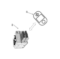
本発明は、例えば図1に示すように、接続対象の例えばプリンタ装置などの他の電子装置50と無線接続して使用される携帯電子機器10に適用される。
For example, as illustrated in FIG. 1, the present invention is applied to a portable
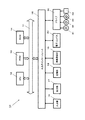
この携帯電子機器10は、図2に示すように、バス11を介して相互に接続されたCPU(Central Processing Unit)12、ROM(Read Only Memory)13、RAM(Random Access Memory)14及び入出力インタフェース15を備える。
As shown in FIG. 2, the portable
この携帯電子機器10において、CPU12は、ROM13又は記憶部18からRAM14にロードされたプログラムに従って各種の処理を実行する。RAM14にはまた、CPU12が各種の処理を実行する上において必要なデータなどが適宜記憶される。
In the portable
入出力インタフェース15には、各種のボタンやジョグダイヤル、或いは、出力部17を構成する例えばLCD(Liquid Crystal Display)に重畳して設けられるタッチパネルなどからなる入力部16、LCDなどよりなる表示部やスピーカなどよりなる出力部17、フラッシュメモリなどよりなる記憶部18が接続されている。
The input /
また、入出力インタフェース15には、IEEE802.11通信規格やブルートゥース通信規格に準拠した無線通信モジュールである無線通信部19も接続されている。無線通信部19は、バス11および入出力インタフェース15を介して行われるCPU12からの制御に従って、図示しない他の電子機器との間でIEEE802.11通信規格に準拠した無線通信を行う。
The input /
さらに、入出力インタフェース15には、この携帯電子機器10の絶対方位を計測する方位検出手段として電子コンパス20が接続されている。
Further, an
入出力インタフェース15にはまた、必要に応じてドライブ30が接続され、磁気ディスク31、光ディスク32、光磁気ディスク33或いは半導体メモリ34などが適宜装着される。
A
このような構成の携帯電子機器10において、無線通信部19は、接続対象の電子装置50から送られてくる無線パケットの電界強度を計測する機能を有し、CPU12は、上記無線通信部19により計測された無線パケットの電界強度に基づいて、当該携帯電子機器10と接続対象の電子装置50との間の大まかな距離を計測することができる。
In the mobile
また、電子コンパス20は、当該携帯電子機器10の絶対方位(地軸に対する方向)を計測して、絶対方位情報を上記CPU12に与える。
Further, the
上記CPU12は、上記無線通信部19により接続対象の電子機器から受信した受信情報、例えば上記無線パケットの電界強度に基づいて、当該携帯電子機器10と接続対象の電子装置50との間の大まかな距離を計測し、当該携帯電子機器10から所定の距離範囲内にある電子装置50を接続候補として特定し、さらに、上記無線通信部19により接続候補の電子機器50から受信した受信情報、すなわち上記無線パケットに含まれる接続候補の電子機器50の方位情報と、上記電子コンパス20により検出された絶対方位情報に基づいて、上記接続候補から接続対象を特定して接続を確立する制御を行う。
The
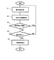
すなわち、この携帯電子機器10では、無線接続を確立する場合、図3のフローチャートに示すように、先ず上記無線通信部19により接続対象の電子機器から受信した無線パケットの電界強度を計測する(ステップS1)。また、当該携帯電子機器10の絶対方位を電子コンパス20により計測して、絶対方位情報を得る(ステップS2)。
That is, in the portable
次に、CPU12により、上記電界強度が閾値以上か否かを判定する(ステップS3)。これにより、当該携帯電子機器10から所定の距離範囲内にある電子装置50を接続候補として特定する。
Next, the
さらに、CPU12により、上記接続候補の電子機器50から受信した無線パケットに含まれる接続候補の電子機器50の方位情報と、上記電子コンパス20により検出された絶対方位情報に基づいて、接続対象の電子機器であるか否かを判定する(ステップS4)。すなわち、当該携帯電子機器10に対して、所定の向きに向いて例えば対向して位置している電子機器50を接続対象として特定する。
Further, the
そして、このようにして上記接続候補から特定した接続対象の電子機器50に対する無線接続を確立する(ステップS5)。
Then, the wireless connection to the connection target
このように、接続対象の電子機器との間で無線通信を行い、受信した受信情報に基づいて接続候補を特定し、上記受信情報に含まれる接続対象の電子機器の方位情報と、当該携帯電子機器10本体の絶対方位情報に基づいて、上記接続候補から接続対象を特定して接続を確立する制御を行う機能を備える携帯電子機器10では、例えば図4に示すように、2台の機器を無線接続する場合に、遠方に位置している機器50Aは距離が遠いので接続対象から除外し、また、近くにあっても向きの違う機器50Bも接続対象から除外して、対向して位置している機器50を接続対象の機器として特定して的確に接続を確立することができる。
In this way, wireless communication is performed with the connection target electronic device, the connection candidate is specified based on the received reception information, the orientation information of the connection target electronic device included in the reception information, and the portable electronic device For example, as shown in FIG. 4, the portable
したがって、周辺に接続対象となる機器が複数個ある場合でも、向きを合わせるという直感的な操作で目的の機器を指定することができ、例えば図5に示すように、ゲーム機器の開始の開始のように人間が機器操作する場合は、対面する相手の機器50を目で確認することが可能であり、また利用者背後に位置する機器50Cは、接続対象から除外することができる。
Therefore, even when there are a plurality of devices to be connected in the vicinity, the target device can be designated by an intuitive operation of matching the orientation. For example, as shown in FIG. As described above, when a person operates a device, it is possible to visually confirm the
また、この携帯電子機器10は、上記電子コンパス20により検出される当該携帯電子機器10の絶対方位情報と、受信した受信情報に含まれる接続対象の電子機器50の方位情報とに基づいて、相互の位置関係を把握することができるので、4人対戦のトランプや麻雀ゲームなど2台以上の機器を接続する場合に、接続した各機器の方向をゲーム内の席順に反映させることができ、実際のユーザの位置関係とゲーム内の順番が空間的に対応しているので、ゲームの対戦相手を把握しやすい。
Further, the portable
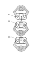
例えば、図6に示すように、麻雀ゲームであれば、親がゲームを召集し、集まった3人のプレイヤーが、親の機器10に対して機器10A,10B,10Cを向けて接続を開始する。その結果、雀卓上での席順が現実の席順を反映するように自動設定することができる。
For example, as shown in FIG. 6, in the case of a mahjong game, the parent summons the game, and the three players gathered point the
また、図7に示すように、接続した機器10a,10b,10c,10dのプレイヤーが敵味方(青チームと赤チーム)に分かれて対戦することもできる。
In addition, as shown in FIG. 7, the players of the
この図7に示す例は、例えばサッカーゲームなどを想定している。この際、同じ方向を向いているプレイヤーが自然に同じチームに属するようにすることができる。チームの構成を変える場合は、各利用者の向きを変えればよい。 The example shown in FIG. 7 assumes a soccer game, for example. At this time, players facing the same direction can naturally belong to the same team. When changing the team structure, the direction of each user should be changed.
10,10A,10B,10C,10a,10b,10c,10d 携帯電子機器、11 バス、12 CPU、13 ROM、14 RAM、15 入出力インタフェース、16 入力部、17 出力部、18 記憶部、19 無線通信部、20 電子コンパス、30 ドライブ、31 磁気ディスク、32 光ディスク、33 光磁気ディスク、34 半導体メモリ、50,50A,50B,50C 電子装置 10, 10A, 10B, 10C, 10a, 10b, 10c, 10d portable electronic device, 11 bus, 12 CPU, 13 ROM, 14 RAM, 15 input / output interface, 16 input unit, 17 output unit, 18 storage unit, 19 wireless Communication unit, 20 electronic compass, 30 drive, 31 magnetic disk, 32 optical disk, 33 magneto-optical disk, 34 semiconductor memory, 50, 50A, 50B, 50C electronic device
Claims (8)
接続対象の電子機器との間で無線通信を行う無線通信手段と、
上記無線通信手段により接続対象の電子機器との間で無線通信による接続を確立する制御を行う制御手段とを備え、
上記制御手段は、上記方位検出手段により検出された絶対方位情報と上記無線通信手段により接続対象の電子機器から受信した受信情報に含まれる電子機器の方位情報に基づいて、複数の接続対象の電子機器の中から、接続対象の電子機機器を選択して、選択された接続対象の電子機器との間で無線通信による接続を確立する制御を行うことを特徴とする携帯電子機器。 Orientation detection means for measuring the absolute orientation of the device body,
Wireless communication means for performing wireless communication with the electronic device to be connected;
Control means for performing control to establish a connection by wireless communication with the electronic device to be connected by the wireless communication means,
The control means, based on the orientation information of the electronic device included in the received information received from the electronic device to be connected by the absolute azimuth information and the wireless communication means detected by said azimuth detection means, a plurality of connection target electronic A portable electronic device that performs control to select a connection target electronic device from among the devices and establish a connection by wireless communication with the selected connection target electronic device.
接続対象の電子機器との間で無線通信を行う無線通信手段と、
上記無線通信手段により接続対象の電子機器との間で無線通信による接続を確立する制御を行う制御手段とを備え、
上記制御手段は、上記無線通信手段により接続対象の電子機器から受信した受信情報に基づいて接続候補を特定し、その受信情報に含まれる接続対象の電子機器の方位情報と、上記方位検出手段により検出された絶対方位情報とに基づいて、上記接続候補の中から携帯電子機器本体の方位と対向する方位を有する電子機器を接続対象として選択して、接続対象の電子機器との間で接続を確立する制御を行うことを特徴とする携帯電子機器。 Orientation detection means for measuring the absolute orientation of the device body,
Wireless communication means for performing wireless communication with the electronic device to be connected;
Control means for performing control to establish a connection by wireless communication with the electronic device to be connected by the wireless communication means,
The control means identifies connection candidates based on the reception information received from the connection target electronic device by the wireless communication means, and includes the direction information of the connection target electronic device included in the reception information and the direction detection means. Based on the detected absolute azimuth information , an electronic device having an azimuth opposite to that of the mobile electronic device main body is selected as a connection target from the connection candidates , and a connection is established with the connection target electronic device. A portable electronic device characterized by performing control to be established.
上記制御手段は、上記電界強度検出手段により検出された電界強度が所定の閾値以上である電子機器のみを接続候補として特定することを特徴とする請求項1又は請求項2に記載の携帯電子機器。 It further comprises electric field strength detection means,
3. The portable electronic device according to claim 1, wherein the control unit specifies only an electronic device whose electric field intensity detected by the electric field intensity detection unit is equal to or greater than a predetermined threshold as a connection candidate. 4. .
上記各携帯電子機器は、機器本体の絶対方位を計測する方位検出手段と、接続対象の電子機器との間で無線通信を行う無線通信手段と、上記無線通信手段により接続対象の電子機器との間で無線通信による接続を確立する制御を行う制御手段とを備え、
上記第1の携帯電子機器の制御手段は、上記方位検出手段により検出された絶対方位情報と上記無線通信手段により第2の携帯電子機器から受信した上記第2の携帯電子機器の絶対方位情報とに基づいて、上記第1の携帯電子機器の周囲に存在する複数の接続対象の電子機器の中から、接続対象の電子機機器として第2の携帯電子機器を選択して、選択された第2の携帯電子機器との間で接続を確立する制御を行うことを特徴とする無線通信システム。 A wireless communication system including first and second portable electronic devices that perform wireless communication with each other ,
Each portable electronic device includes an orientation detection unit that measures the absolute orientation of the device body, a wireless communication unit that performs wireless communication with the connection target electronic device, and a connection target electronic device that includes the wireless communication unit. Control means for performing control to establish a connection by wireless communication between,
Control means of said first portable electronic device, the absolute azimuth information of the second mobile electronic device is received from the second portable electronic device by the absolute azimuth information and the wireless communication means detected by said azimuth detection means The second portable electronic device is selected as the connection target electronic device from the plurality of connection target electronic devices existing around the first portable electronic device, and the selected second device is selected. A wireless communication system that performs control to establish a connection with a portable electronic device .
上記各携帯電子機器は、機器本体の絶対方位を計測する方位検出手段と、接続対象の電子機器との間で無線通信を行う無線通信手段と、上記無線通信手段により接続対象の電子機器との間で無線通信による接続を確立する制御を行う制御手段とを備え、Each portable electronic device includes an orientation detection unit that measures the absolute orientation of the device body, a wireless communication unit that performs wireless communication with the connection target electronic device, and a connection target electronic device that includes the wireless communication unit. Control means for performing control to establish a connection by wireless communication between,
上記第1の携帯電子機器の制御手段は、上記第2の携帯電子機器の絶対方位情報が、上記第1の携帯電子機器の絶対方位情報と対向する方位を示すものである場合のみ、上記第2の携帯電子機器との間で接続を確立する制御を行うことを特徴とする無線通信システム。The control means of the first portable electronic device is configured so that the absolute direction information of the second portable electronic device indicates the direction opposite to the absolute direction information of the first portable electronic device. A wireless communication system that performs control for establishing a connection with two portable electronic devices.
上記第1の携帯電子機器の上記制御手段は、上記電界強度検出手段により検出された第2の携帯電子機器の電界強度が所定の閾値以上である場合にのみ、当該第2の携帯電子機器との間で接続を確立することを特徴とする請求項4又は請求項5に記載の無線通信システム。 At least the first portable electronic device includes electric field strength detection means,
Said control means of said first portable electronic device, the electric field intensity of the second portable electronic device is detected by the field intensity detection means only when equal to or greater than a predetermined threshold, and said second portable electronic device the wireless communication system according to claim 4 or claim 5, characterized in that between establishing a connection.
接続対象の電子機器との間で無線通信を行い、
受信した受信情報に基づいて複数の接続候補の電子機器を特定し、
上記受信情報に含まれる接続対象の電子機器の方位情報と、当該携帯電子機器本体の絶対方位情報とに基づいて、複数の接続候補の電子機器の中から、接続対象の電子機機器を選択して、選択された接続対象の電子機器との間で無線通信による接続を確立する制御を行うことを特徴とする携帯電子機器の無線接続制御方法。 A wireless connection control method for a portable electronic device for wirelessly connecting the portable electronic device to an electronic device to be connected,
Wireless communication with the electronic device to be connected,
Identify multiple connection candidate electronic devices based on the received information received,
And orientation information of a target for connection of electronic devices included in the received information, based on the absolute direction information of the portable electronic device main body, from among the electronic devices of the plurality of connection candidate, select the electronic equipment apparatus to be connected A wireless connection control method for a portable electronic device, wherein control for establishing a connection by wireless communication with the selected electronic device to be connected is performed.
接続対象の電子機器との間で無線通信を行い、 Wireless communication with the electronic device to be connected,
受信した受信情報に基づいて複数の接続候補の電子機器を特定し、 Identify multiple connection candidate electronic devices based on the received information received,
上記接続対象の電子機器から受信した受信情報に基づいて接続候補を特定し、その受信情報に含まれる接続対象の電子機器の方位情報と、当該携帯電子機器本体の絶対方位情報とに基づいて、上記接続候補の中から携帯電子機器本体の方位と対向する方位を有する電子機器を接続対象として選択して、接続対象の電子機器との間で接続を確立する制御を行うことを特徴とする携帯電子機器の無線接続制御方法。 Based on the reception information received from the connection target electronic device, identify the connection candidate, based on the orientation information of the connection target electronic device included in the reception information, and the absolute orientation information of the mobile electronic device body, A portable device comprising: selecting an electronic device having an orientation opposite to the orientation of the portable electronic device main body as a connection target from the connection candidates, and performing control for establishing a connection with the connection target electronic device. A method for controlling wireless connection of electronic devices.
Priority Applications (2)
| Application Number | Priority Date | Filing Date | Title |
|---|---|---|---|
| JP2004138910A JP4111165B2 (en) | 2004-05-07 | 2004-05-07 | Portable electronic device, wireless communication system and wireless connection control method thereof |
| US11/106,923 US7289800B2 (en) | 2004-05-07 | 2005-04-15 | Portable electronic device and wireless connection control method therefor |
Applications Claiming Priority (1)
| Application Number | Priority Date | Filing Date | Title |
|---|---|---|---|
| JP2004138910A JP4111165B2 (en) | 2004-05-07 | 2004-05-07 | Portable electronic device, wireless communication system and wireless connection control method thereof |
Publications (3)
| Publication Number | Publication Date |
|---|---|
| JP2005323091A JP2005323091A (en) | 2005-11-17 |
| JP2005323091A5 JP2005323091A5 (en) | 2006-01-05 |
| JP4111165B2 true JP4111165B2 (en) | 2008-07-02 |
Family
ID=35470035
Family Applications (1)
| Application Number | Title | Priority Date | Filing Date |
|---|---|---|---|
| JP2004138910A Expired - Fee Related JP4111165B2 (en) | 2004-05-07 | 2004-05-07 | Portable electronic device, wireless communication system and wireless connection control method thereof |
Country Status (2)
| Country | Link |
|---|---|
| US (1) | US7289800B2 (en) |
| JP (1) | JP4111165B2 (en) |
Cited By (2)
| Publication number | Priority date | Publication date | Assignee | Title |
|---|---|---|---|---|
| US10251207B2 (en) | 2015-03-13 | 2019-04-02 | Rakuten, Inc. | Wireless mobile communication apparatus, wireless communication method and program |
| US10623901B2 (en) | 2015-03-13 | 2020-04-14 | Rakuten, Inc. | Wireless mobile communication apparatus, wireless communication method and program |
Families Citing this family (12)
| Publication number | Priority date | Publication date | Assignee | Title |
|---|---|---|---|---|
| TWI273782B (en) * | 2005-07-25 | 2007-02-11 | Sin Etke Technology Co Ltd | Short-distance wireless transmission system of electric device in vehicle |
| JP2007158447A (en) * | 2005-11-30 | 2007-06-21 | Canon Inc | Radio communication device |
| JP4699886B2 (en) * | 2005-12-06 | 2011-06-15 | 株式会社日立製作所 | Device setting system and device setting method |
| DE102005059522A1 (en) * | 2005-12-13 | 2007-06-14 | Siemens Ag | Communication system of a motor vehicle and method for establishing a wireless ad hoc wireless network |
| JP2007318441A (en) * | 2006-05-25 | 2007-12-06 | Toshiba Corp | Communication terminal device |
| KR100690243B1 (en) * | 2006-06-07 | 2007-03-12 | 삼성전자주식회사 | Apparatus and method for controlling of the camera in a portable terminal |
| US8055191B2 (en) * | 2007-05-30 | 2011-11-08 | Sony Corporation | Method and structure in support of the formation of substantially co-linear wireless device pairings and mitigation of interference effects in a digital multi-media communication environment |
| JP2010161654A (en) * | 2009-01-08 | 2010-07-22 | Sony Ericsson Mobilecommunications Japan Inc | Communication terminal and communication method |
| WO2013014744A1 (en) * | 2011-07-26 | 2013-01-31 | パイオニア株式会社 | Wireless communication device, wireless communication method, wireless communication program, and recording medium which stores wireless communication program |
| TWI434519B (en) | 2011-11-29 | 2014-04-11 | Arcadyan Technology Corp | Handheld electronic device and handheld communication remote control method |
| JP5922050B2 (en) * | 2013-03-07 | 2016-05-24 | 株式会社日立製作所 | Distributed computer system for railway vehicles and operation control method thereof |
| JP6515705B2 (en) * | 2015-06-30 | 2019-05-22 | 株式会社リコー | INFORMATION PROCESSING APPARATUS, INFORMATION PROCESSING SYSTEM, INFORMATION PROCESSING METHOD, AND PROGRAM |
Family Cites Families (8)
| Publication number | Priority date | Publication date | Assignee | Title |
|---|---|---|---|---|
| JP4868195B2 (en) | 2000-10-24 | 2012-02-01 | ソニー株式会社 | Electronic apparatus and information processing apparatus |
| JP3522686B2 (en) * | 2000-12-13 | 2004-04-26 | 松下電器産業株式会社 | Mobile terminal, automatic remote control system and automatic remote control method |
| JP4726306B2 (en) * | 2001-01-31 | 2011-07-20 | パナソニック株式会社 | Wireless communication system, mobile terminal station and direction determination method |
| JP3716801B2 (en) * | 2002-02-27 | 2005-11-16 | ヤマハ株式会社 | Vehicle position communication system and portable communication device |
| US20030216139A1 (en) * | 2002-05-16 | 2003-11-20 | Johnson Controls Technology Company | System and method for wireless control of remote electronic systems based on timing information |
| CA2495227A1 (en) * | 2002-08-13 | 2004-02-19 | Drs Communications Company, Llc | Method and system for determining relative positions of networked mobile communication devices |
| KR101168423B1 (en) * | 2003-02-05 | 2012-07-25 | 가부시키가이샤 자나비 인포메틱스 | Path search method of navigation apparatus and display method of traffic information |
| JP4255007B2 (en) * | 2003-04-11 | 2009-04-15 | 株式会社ザナヴィ・インフォマティクス | Navigation device and travel time calculation method thereof |
-
2004
- 2004-05-07 JP JP2004138910A patent/JP4111165B2/en not_active Expired - Fee Related
-
2005
- 2005-04-15 US US11/106,923 patent/US7289800B2/en not_active Expired - Fee Related
Cited By (2)
| Publication number | Priority date | Publication date | Assignee | Title |
|---|---|---|---|---|
| US10251207B2 (en) | 2015-03-13 | 2019-04-02 | Rakuten, Inc. | Wireless mobile communication apparatus, wireless communication method and program |
| US10623901B2 (en) | 2015-03-13 | 2020-04-14 | Rakuten, Inc. | Wireless mobile communication apparatus, wireless communication method and program |
Also Published As
| Publication number | Publication date |
|---|---|
| JP2005323091A (en) | 2005-11-17 |
| US7289800B2 (en) | 2007-10-30 |
| US20060109143A1 (en) | 2006-05-25 |
Similar Documents
| Publication | Publication Date | Title |
|---|---|---|
| US7289800B2 (en) | Portable electronic device and wireless connection control method therefor | |
| US20170052606A1 (en) | Motion Based Input Selection | |
| US8542834B1 (en) | System and method for securely pairing a wireless peripheral to a host | |
| US7987364B2 (en) | Method of detecting and authenticating connection target for wireless communication apparatus | |
| US20150189681A1 (en) | Communication apparatus | |
| US9032479B2 (en) | Method, mobile terminal and system for providing different authentication values according to contact method of mobile terminal | |
| CN110431868B (en) | Wi-Fi hotspot connection method and terminal | |
| EP3401864A1 (en) | Method for selecting transaction application, and terminal | |
| CN107071775B (en) | Mobile terminal and method and device for redirecting access to base station | |
| CN110169153A (en) | Wireless communication system | |
| US9165415B2 (en) | Method and apparatus for access authentication using mobile terminal | |
| JP2008098893A (en) | Wireless communication module, and wireless communication system | |
| JP2006352577A (en) | Radio communication system, radio communication setting method, radio communication apparatus, radio communication setting program, and storage medium thereof | |
| KR20160124636A (en) | Mobile terminal and method for controlling the same | |
| US10009834B2 (en) | Apparatus and method for accessing electronic device having hot spot function | |
| JP2010161654A (en) | Communication terminal and communication method | |
| JP2015194947A (en) | Information processing device and computer program | |
| US7986967B2 (en) | Wireless communication system and method | |
| JP5903870B2 (en) | Access control system and wireless portable terminal | |
| US10024659B2 (en) | System and method for intelligently coupling and connecting mobile terminals to a coordinate-measuring device | |
| JP2015126300A (en) | Communication device, control method thereof, and program | |
| US8934940B1 (en) | Providing enhanced security for wireless telecommunications devices | |
| KR101571015B1 (en) | System and method for detecting and blocking illegal access point | |
| KR102033980B1 (en) | Device and method for transmitting/receiving data using security usb dongle | |
| CN109257441B (en) | Wireless local area network position acquisition method and device |
Legal Events
| Date | Code | Title | Description |
|---|---|---|---|
| A521 | Request for written amendment filed |
Free format text: JAPANESE INTERMEDIATE CODE: A523 Effective date: 20051011 |
|
| A621 | Written request for application examination |
Free format text: JAPANESE INTERMEDIATE CODE: A621 Effective date: 20051011 |
|
| A977 | Report on retrieval |
Free format text: JAPANESE INTERMEDIATE CODE: A971007 Effective date: 20071127 |
|
| A131 | Notification of reasons for refusal |
Free format text: JAPANESE INTERMEDIATE CODE: A131 Effective date: 20071204 |
|
| A521 | Request for written amendment filed |
Free format text: JAPANESE INTERMEDIATE CODE: A523 Effective date: 20080131 |
|
| TRDD | Decision of grant or rejection written | ||
| A01 | Written decision to grant a patent or to grant a registration (utility model) |
Free format text: JAPANESE INTERMEDIATE CODE: A01 Effective date: 20080318 |
|
| A61 | First payment of annual fees (during grant procedure) |
Free format text: JAPANESE INTERMEDIATE CODE: A61 Effective date: 20080331 |
|
| FPAY | Renewal fee payment (event date is renewal date of database) |
Free format text: PAYMENT UNTIL: 20110418 Year of fee payment: 3 |
|
| FPAY | Renewal fee payment (event date is renewal date of database) |
Free format text: PAYMENT UNTIL: 20110418 Year of fee payment: 3 |
|
| FPAY | Renewal fee payment (event date is renewal date of database) |
Free format text: PAYMENT UNTIL: 20120418 Year of fee payment: 4 |
|
| FPAY | Renewal fee payment (event date is renewal date of database) |
Free format text: PAYMENT UNTIL: 20120418 Year of fee payment: 4 |
|
| FPAY | Renewal fee payment (event date is renewal date of database) |
Free format text: PAYMENT UNTIL: 20130418 Year of fee payment: 5 |
|
| LAPS | Cancellation because of no payment of annual fees |