EP1178329A1 - Appareil et méthode de correction de la position d'un corps mobile dans un système de navigation - Google Patents
Appareil et méthode de correction de la position d'un corps mobile dans un système de navigation Download PDFInfo
- Publication number
- EP1178329A1 EP1178329A1 EP01121937A EP01121937A EP1178329A1 EP 1178329 A1 EP1178329 A1 EP 1178329A1 EP 01121937 A EP01121937 A EP 01121937A EP 01121937 A EP01121937 A EP 01121937A EP 1178329 A1 EP1178329 A1 EP 1178329A1
- Authority
- EP
- European Patent Office
- Prior art keywords
- movable body
- present position
- data
- self
- distance data
- Prior art date
- Legal status (The legal status is an assumption and is not a legal conclusion. Google has not performed a legal analysis and makes no representation as to the accuracy of the status listed.)
- Granted
Links
Images


Classifications
-
- G—PHYSICS
- G01—MEASURING; TESTING
- G01S—RADIO DIRECTION-FINDING; RADIO NAVIGATION; DETERMINING DISTANCE OR VELOCITY BY USE OF RADIO WAVES; LOCATING OR PRESENCE-DETECTING BY USE OF THE REFLECTION OR RERADIATION OF RADIO WAVES; ANALOGOUS ARRANGEMENTS USING OTHER WAVES
- G01S19/00—Satellite radio beacon positioning systems; Determining position, velocity or attitude using signals transmitted by such systems
- G01S19/38—Determining a navigation solution using signals transmitted by a satellite radio beacon positioning system
- G01S19/39—Determining a navigation solution using signals transmitted by a satellite radio beacon positioning system the satellite radio beacon positioning system transmitting time-stamped messages, e.g. GPS [Global Positioning System], GLONASS [Global Orbiting Navigation Satellite System] or GALILEO
- G01S19/40—Correcting position, velocity or attitude
-
- G—PHYSICS
- G01—MEASURING; TESTING
- G01C—MEASURING DISTANCES, LEVELS OR BEARINGS; SURVEYING; NAVIGATION; GYROSCOPIC INSTRUMENTS; PHOTOGRAMMETRY OR VIDEOGRAMMETRY
- G01C21/00—Navigation; Navigational instruments not provided for in groups G01C1/00 - G01C19/00
- G01C21/10—Navigation; Navigational instruments not provided for in groups G01C1/00 - G01C19/00 by using measurements of speed or acceleration
- G01C21/12—Navigation; Navigational instruments not provided for in groups G01C1/00 - G01C19/00 by using measurements of speed or acceleration executed aboard the object being navigated; Dead reckoning
- G01C21/16—Navigation; Navigational instruments not provided for in groups G01C1/00 - G01C19/00 by using measurements of speed or acceleration executed aboard the object being navigated; Dead reckoning by integrating acceleration or speed, i.e. inertial navigation
- G01C21/165—Navigation; Navigational instruments not provided for in groups G01C1/00 - G01C19/00 by using measurements of speed or acceleration executed aboard the object being navigated; Dead reckoning by integrating acceleration or speed, i.e. inertial navigation combined with non-inertial navigation instruments
-
- G—PHYSICS
- G01—MEASURING; TESTING
- G01C—MEASURING DISTANCES, LEVELS OR BEARINGS; SURVEYING; NAVIGATION; GYROSCOPIC INSTRUMENTS; PHOTOGRAMMETRY OR VIDEOGRAMMETRY
- G01C21/00—Navigation; Navigational instruments not provided for in groups G01C1/00 - G01C19/00
- G01C21/26—Navigation; Navigational instruments not provided for in groups G01C1/00 - G01C19/00 specially adapted for navigation in a road network
- G01C21/28—Navigation; Navigational instruments not provided for in groups G01C1/00 - G01C19/00 specially adapted for navigation in a road network with correlation of data from several navigational instruments
- G01C21/30—Map- or contour-matching
-
- G—PHYSICS
- G01—MEASURING; TESTING
- G01S—RADIO DIRECTION-FINDING; RADIO NAVIGATION; DETERMINING DISTANCE OR VELOCITY BY USE OF RADIO WAVES; LOCATING OR PRESENCE-DETECTING BY USE OF THE REFLECTION OR RERADIATION OF RADIO WAVES; ANALOGOUS ARRANGEMENTS USING OTHER WAVES
- G01S19/00—Satellite radio beacon positioning systems; Determining position, velocity or attitude using signals transmitted by such systems
- G01S19/38—Determining a navigation solution using signals transmitted by a satellite radio beacon positioning system
- G01S19/39—Determining a navigation solution using signals transmitted by a satellite radio beacon positioning system the satellite radio beacon positioning system transmitting time-stamped messages, e.g. GPS [Global Positioning System], GLONASS [Global Orbiting Navigation Satellite System] or GALILEO
- G01S19/42—Determining position
- G01S19/48—Determining position by combining or switching between position solutions derived from the satellite radio beacon positioning system and position solutions derived from a further system
- G01S19/49—Determining position by combining or switching between position solutions derived from the satellite radio beacon positioning system and position solutions derived from a further system whereby the further system is an inertial position system, e.g. loosely-coupled
-
- G—PHYSICS
- G01—MEASURING; TESTING
- G01S—RADIO DIRECTION-FINDING; RADIO NAVIGATION; DETERMINING DISTANCE OR VELOCITY BY USE OF RADIO WAVES; LOCATING OR PRESENCE-DETECTING BY USE OF THE REFLECTION OR RERADIATION OF RADIO WAVES; ANALOGOUS ARRANGEMENTS USING OTHER WAVES
- G01S19/00—Satellite radio beacon positioning systems; Determining position, velocity or attitude using signals transmitted by such systems
- G01S19/01—Satellite radio beacon positioning systems transmitting time-stamped messages, e.g. GPS [Global Positioning System], GLONASS [Global Orbiting Navigation Satellite System] or GALILEO
- G01S19/13—Receivers
Definitions
- the present invention relates to a method of and apparatus for correcting a present position of a movable body onto a position on a route, where said movable body is supposed to exist, corresponding to the present position for use in a navigation system for navigating said body.
- navigation apparatus which displays a map including a position where a movable body in various kinds such as an automobile, an airplane, a ship etc., is currently located, and further superimposes a position mark indicating a position of the movable body at the currently located position on the displayed map, so as to perform a route guidance or navigation to the destination on the basis of the display.
- navigation apparatuses as on-vehicle navigation apparatuses which are mounted on vehicles or auto-mobiles, there is a self-sustained or built-in type navigation apparatus and a GPS (Global Positioning System) type navigation apparatus as rough categories.
- the former is a navigation apparatus, which obtains a moving direction and a moving distance of the movable body by use of self-sustained type or built-in type sensors such as a speed sensor, an angular speed sensor etc. equipped in or built in the pertinent vehicle, sequentially adds them with respect to a standard position so as to calculate the present position, and displays the present position mark and the corresponding map on the display picture plane on the basis of the calculated present position.
- self-sustained type or built-in type sensors such as a speed sensor, an angular speed sensor etc. equipped in or built in the pertinent vehicle, sequentially adds them with respect to a standard position so as to calculate the present position, and displays the present position mark and the corresponding map on the display picture plane on the basis of the calculated present position.
- the latter is a navigation apparatus, which receives measurement electric waves from a plurality of GPS satellites launched in the space by a GPS receiver, calculates the present position of the movable body by means of a 3-dimensional measuring method or a 2-dimensional measuring method on the basis of the electric wave reception results, and displays the present position mark and the corresponding map on the display picture plane on the basis of the calculated present position.
- the measurement electric wave from a satellite dedicated for positional measurement is transmitted such that time data indicating time is superimposed thereon.
- a GPS receiver in the on-vehicle navigation system of hybrid type outputs time information indicating the time at receiving the measurement electric wave, on the basis of the superimposed time data, together with present position information indicating a present position measured on the basis of the received measurement electric waves. Therefore, a CPU used in the on-vehicle navigation system of hybrid type is adapted to calculate the present position by synthesizing the present position information accompanied with the outputted time information based on the measurement electric wave, and the present position information calculated by the self-sustained type sensors.
- the time axis for the present position information which is accompanied by the time information outputted on the basis of the measurement electric waves
- the time axis for the present position information calculated by the self-sustained type sensors are not synchronized with each other.
- the calculation cycle may be changed to 1.5 seconds, for example.
- the calculated measurement result actually indicates the position of the movable body which is about 1 to 2 seconds before the present time.
- the time axis for the present position information which is outputted on the basis of the measurement electric waves, and the time axis for the present position information calculated by the self-sustained type sensors are not inevitably synchronized with each other. Consequently, the correction or the like for the present position information based on the self-sustained type sensors by use of the present position information based on the measurement electric waves, cannot be effectively applied due to the shift of these time axes.
- the self-sustained type sensors output the present position information almost accurately once every second, there may be such a case that all of the present position information is not regularly inputted to the CPU. Thus, particularly, the distance information in the present position information based on the self-sustained type sensors becomes inaccurate, which is the second problem.
- a distance error is generated.
- this distance information is dropped out and is not taken into the CPU, for example, there are a case where the distance data itself is destroyed by a physical noise generated on a communication line from the self-sustained type sensors to the CPU, a case where the distance data cannot be taken into the CPU for a while since the CPU performs a process for other information having a higher priority such as traffic jam information from the VICS (Vehicle Information and Communication System), which has been just put into practice, and so on. Then, the distance error becomes large as the case where the distance data cannot be taken happens more frequently, so that the present position cannot be accurately measured or displayed.
- VICS Vehicle Information and Communication System
- the on-vehicle navigation system even if the self vehicle is actually traveling on a road for example, there may be such a case that the calculated present position indicates a position which is not on the road due to the measurement error or the like.
- a so-called map matching process is performed to correct the display position of the present position onto a position on a road, which is the closest to the measured present position P 3 obtained by calculating the moving vector V with respect to the previous display position of the present position as a standard, and displays the present position on the correct displayed position (i. e. a presently map matched position P 2 ).
- the position after the map matching process is displayed as the present position.
- the above general object can be achieved by a first method of calculating a present position of a movable body, such as a vehicle etc., for use in a navigation system for navigating the movable body.
- the first method is provided with: an electric-wave-based measurement process of measuring an electric-wave-based measurement position which is a position of the movable body measured on the basis of electric waves for positional measurement, which are transmitted from satellites, such as GPS satellites etc., accompanied by time data indicating an electric-wave-based measurement time which is a time when measuring the electric-wave-based measurement position, at the electric-wave-based measurement time; a self-sustained measurement process of measuring a self-sustained measurement position which is a position of the movable body measured on the basis of data from self-sustained type sensors, such as a travel distance sensor etc., built in the movable body; a time difference calculation process of calculating a time difference between the electric-wave-based measurement time and a time when measuring the self-sus
- an electric-wave-based measurement position of the movable body is measured on the basis of the electric waves at the electric-wave-based measurement time, by the electric-wave-based measurement process.
- a self-sustained measurement position of the movable body is measured on the basis of the data from the self-sustained type sensors, such as a travel distance sensor, an angular speed sensor etc., without using the electric waves, by the self-sustained measurement process.
- a time difference between the electric-wave-based measurement time and the time when measuring the self-sustained measurement position by the self-sustained measurement process is calculated by the time difference calculation process.
- the electric-wave-based measurement position is corrected on the basis of the calculated time difference, by the correction process.
- the present position of the movable body is calculated on the basis of the corrected electric-wave-based measurement position and the self-sustained measurement position, by the present position calculation process.
- the present position of the movable body is calculated by correcting this time difference. Therefore, an accurate present position of the movable body can be calculated in consideration of the time difference.
- the correction process corrects the electric-wave-based measurement position by superimposing a moving distance of the movable body, which corresponds to the calculated time difference and is calculated on the basis of the data from the self-sustained type sensors, onto the electric-wave-based measurement position, so as to calculate the corrected electric-wave-based measurement position.
- the corrected electric-wave-based measurement position is calculated in such a manner that the electric-wave-based measurement position is corrected by superimposing a moving distance of the movable body, which corresponds to the calculated time difference and is calculated on the basis of the data from the self-sustained type sensors, onto the electric-wave-based measurement position. Accordingly, it is possible to calculate the accurate present position by a rather simple process.
- the above general object can be also achieved by a second method of calculating a present position of a movable body, such as a vehicle etc., for use in a navigation system having a distance sensor for navigating the movable body, the distance sensor cyclically outputting distance data, which indicates a moving distance of the movable body measured in a self-sustained way once every predetermined cycle and includes an identifier, such as identification data etc., for identifying the distance data at each cycle.
- the second method is provided with: a distance measurement process of outputting the distance data one after another in connection with a movement of the movable body; a drop out detection process of detecting a drop out of the distance data on the basis of the identifier included in the outputted distance data; a pseudo distance data generation process of generating pseudo distance data corresponding to the dropped out distance data on the basis of the distance data outputted before the dropped out distance data and the distance data outputted after the dropped out distance data, when the drop out is detected by the drop out detection process; a moving distance calculation process of calculating the moving distance by adding the generated pseudo distance data onto the distance data outputted after the dropped out distance data, when the drop out is detected by the drop out detection process; and a present position calculation process of calculating the present position of the movable body on the basis of the calculated moving distance.
- distance data is outputted one after another in connection with a movement of the movable body, by the distance measurement process.
- a drop out of the distance data is detected on the basis of the identifier included in the outputted distance data, by the drop out detection process.
- pseudo distance data corresponding to the dropped out distance data is generated on the basis of the distance data outputted before the dropped out distance data and the distance data outputted after the dropped out distance data, by the pseudo distance data generation process.
- the moving distance is calculated by adding the generated pseudo distance data onto the distance data outputted after the dropped out distance data, by the moving distance calculation process.
- the present position of the movable body is calculated on the basis of the calculated moving distance, by the present position calculation process.
- the dropped out distance data is approximately interpolated by the pseudo distance data, so that the moving distance is calculated. Therefore, by use of this calculated moving distance, an accurate present position of the movable body can be calculated.
- the above object of the present invention is achieved by a third method of correcting a present position of a movable body, such as a vehicle etc., onto a position on a route, where the movable body is supposed to exist, corresponding to the present position for use in a navigation system for navigating the movable body.
- the third method is provided with: a vector generation process of generating a moving vector corresponding to a movement of the movable body with respect to a previously corrected position of the movable body as a start point of the moving vector; a display process of displaying a position of an end point of the generated moving vector as the present position of the movable body; and a correct process of correcting the position of the end point to a position on the route corresponding to the position of the end point after displaying the position of the end point by the display process.
- a moving vector corresponding to a movement of the movable body with respect to a previously corrected position of the movable body as a start point of the moving vector is generated by the vector generation process. Then, a position of an end point of the generated moving vector is displayed as the present position of the movable body, by the display process. After displaying the position of the end point by the display process, the position of the end point is corrected to a position on the route corresponding to the position of the end point, by the correct process.
- the present position can be displayed without including the error corresponding to the time required for correcting the position onto the route, in contrast to a case where the corrected position is displayed after correcting the position of the end point of the moving vector onto the route.
- the third method is further provided with a re-display process of displaying the corrected position on the route as the present position of the movable body.
- the corrected position on the route is displayed as the present position of the movable body, by the re-display process. Therefore, it is possible to accurately display the present position of the movable body on the route.
- the above general object can be also achieved by a first apparatus for calculating a present position of a movable body, such as a vehicle etc., for use in a navigation system for navigating the movable body.
- the first apparatus is provided with: an electric-wave-based measurement device, such as a GPS receiver etc., for measuring an electric-wave-based measurement position which is a position of the movable body measured on the basis of electric waves for positional measurement, which are transmitted from satellites, such as GPS satellites etc., accompanied by time data indicating an electric-wave-based measurement time which is a time when measuring the electric-wave-based measurement position, at the electric-wave-based measurement time; a self-sustained measurement device, such as a CPU etc., for measuring a self-sustained measurement position which is a position of the movable body measured on the basis of data from self-sustained type sensors, such as a travel distance sensor etc., built in the movable body; a time difference calculation device, such as a CPU etc
- an electric-wave-based measurement position of the movable body is measured on the basis of the electric waves at the electric-wave-based measurement time, by the electric-wave-based measurement device.
- a self-sustained measurement position of the movable body is measured on the basis of the data from the self-sustained type sensors, such as a travel distance sensor, an angular speed sensor etc., without using the electric waves, by the self-sustained measurement device.
- a time difference between the electric-wave-based measurement time and the time when measuring the self-sustained measurement position by the self-sustained measurement device is calculated by the time difference calculation device.
- the electric-wave-based measurement position is corrected on the basis of the calculated time difference, by the correction device.
- the present position of the movable body is calculated on the basis of the corrected electric-wave-based measurement position and the self-sustained measurement position, by the present position calculation device.
- the present position of the movable body is calculated by correcting this time difference. Therefore, an accurate present position of the movable body can be calculated in consideration of the time difference.
- the correction device corrects the electric-wave-based measurement position by superimposing a moving distance of the movable body, which corresponds to the calculated time difference and is calculated on the basis of the data from the self-sustained type sensors, onto the electric-wave-based measurement position, so as to calculate the corrected electric-wave-based measurement position.
- the corrected electric-wave-based measurement position is calculated in such a manner that the electric-wave-based measurement position is corrected by superimposing a moving distance of the movable body, which corresponds to the calculated time difference and is calculated on the basis of the data from the self-sustained type sensors, onto the electric-wave-based measurement position. Accordingly, it is possible to calculate the accurate present position by a rather simple device.
- the second apparatus is provided with: a distance measurement device for outputting the distance data one after another in connection with a movement of the movable body; a drop out detection device, such as a CPU etc., for detecting a drop out of the distance data on the basis of the identifier included in the outputted distance data; a pseudo distance data generation device, such as a CPU etc., for generating pseudo distance data corresponding to the dropped out distance data on the basis of the distance data outputted before the dropped out distance data and the distance data outputted after the dropped out distance data, when the drop out is detected by the drop out detection device; a moving distance calculation device, such as a CPU etc., for calculating the moving distance by adding the generated pseudo distance data onto the distance data outputted after the dropped out distance data, when the drop out is detected by the drop out detection device; and a present position calculation device, such as a CPU etc., for calculating the present position of the movable body on the basis of the calculated moving distance.
- a distance measurement device for outputting the distance data one after another
- distance data is outputted one after another in connection with a movement of the movable body, by the distance measurement device.
- a drop out of the distance data is detected on the basis of the identifier included in the outputted distance data, by the drop out detection device.
- pseudo distance data corresponding to the dropped out distance data is generated on the basis of the distance data outputted before the dropped out distance data and the distance data outputted after the dropped out distance data, by the pseudo distance data generation device.
- the moving distance is calculated by adding the generated pseudo distance data onto the distance data outputted after the dropped out distance data, by the moving distance calculation device.
- the present position of the movable body is calculated on the basis of the calculated moving distance, by the present position calculation device.
- the dropped out distance data is approximately interpolated by the pseudo distance data, so that the moving distance is calculated. Therefore, by use of this calculated moving distance, an accurate present position of the movable body can be calculated.
- a third apparatus for correcting a present position of a movable body, such as a vehicle etc., onto a position on a route, where the movable body is supposed to exist, corresponding to the present position for use in a navigation system for navigating the movable body.
- the third apparatus is provided with: a vector generation device, such as a CPU etc., for generating a moving vector corresponding to a movement of the movable body with respect to a previously corrected position of the movable body as a start point of the moving vector; a display device, such as a display etc., for displaying a position of an end point of the generated moving vector as the present position of the movable body; and a correct device, such as a CPU etc., for correcting the position of the end point to a position on the route corresponding to the position of the end point after displaying the position of the end point by the display device.
- a vector generation device such as a CPU etc.
- a moving vector corresponding to a movement of the movable body with respect to a previously corrected position of the movable body as a start point of the moving vector is generated by the vector generation device. Then, a position of an end point of the generated moving vector is displayed as the present position of the movable body, by the display device. After displaying the position of the end point by the display device, the position of the end point is corrected to a position on the route corresponding to the position of the end point, by the correct device.
- the present position can be displayed without including the error corresponding to the time required for correcting the position onto the route, in contrast to a case where the corrected position is displayed after correcting the position of the end point of the moving vector onto the route.
- the display device displays the corrected position on the route as the present position of the movable body.
- the corrected position on the route is displayed as the present position of the movable body, by the display device. Therefore, it is possible to accurately display the present position of the movable body on the route.
- an on-vehicle navigation apparatus S is provided with: an angular speed sensor 1 for detecting an angular speed of a self vehicle at a time of turning or rotating, and outputting an angular speed data and a relative azimuth data; a travel distance sensor 2 for calculating the number of pulses per one rotation of a drive shaft by counting the number of pulses of a pulse signal having a predetermined cycle accompanying the rotation of the drive shaft, and for outputting travel distance data based on the number of pulses per one rotation of the drive shaft; a GPS receiver 3 for receiving electric waves from GPS satellites to output GPS measurement data, and for outputting absolute azimuth data of the advance direction of the self vehicle; a system controller 4 for performing an overall control of the navigation apparatus S on the basis of the relative azimuth data, the angular speed data, the travel distance data, the GPS measurement data and the absolute azimuth data; an input device 10 for inputting various data, such as an operation panel, a remote-control device or the like; a CD-ROM
- the system controller 4 is provided with: an interface portion 5 for executing an interface operation with external sensors e.g. the angular speed sensor 1, the travel distance sensor 2 and the GPS receiver 3; a CPU 6 for controlling the whole portion of the system controller 4; a ROM (Read Only Memory) 7 for storing a control program etc. to control the system controller 4; and a RAM (Random Access Memory) 8 having a non-volatile type memory for storing various data such as the route data set in advance by the user through the input device 10, in the random accessing manner.
- the input device 10, the CD-ROM drive 11, the display unit 12 and the audio reproduction unit reference 17 are all connected with the system controller 4 via a bus line 9.
- the display unit 12 is provided with: a graphic controller 13 for performing an overall control of the display unit 12 on the basis of a control data transmitted from the CPU 6 through the bus line 9; a buffer memory 14 having a VRAM (Video RAM) etc., for temporarily storing the image information ready to be displayed; and a display control unit 15 for controlling a display 16 such as the LCD device, the CRT display device or the like, on the basis of the image data outputted from the graphic controller 13.
- a graphic controller 13 for performing an overall control of the display unit 12 on the basis of a control data transmitted from the CPU 6 through the bus line 9
- a buffer memory 14 having a VRAM (Video RAM) etc., for temporarily storing the image information ready to be displayed
- a display control unit 15 for controlling a display 16 such as the LCD device, the CRT display device or the like, on the basis of the image data outputted from the graphic controller 13.
- the audio reproduction unit 17 is provided with a D/A (Digital to Analog) converter 18 for performing a D/A conversion of audio digital data transmitted from the CD-ROM drive 11 or the RAM 8 through the bus line 9; an amplifier 19 for amplifying an audio analog signal from the D/A converter 18; and a speaker 20 for converting the amplified audio analog signal to the audio sound, and for outputting it to the external.
- D/A Digital to Analog
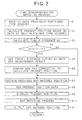
- the operation indicated by the flow charts in the embodiments hereinbelow is mainly performed by the CPU 6, and is performed as one part of the main navigation program to perform the navigation operation by controlling the whole portion of the on-vehicle navigation apparatus S. Therefore, during the execution of the main navigation program, the operation indicated by the flow chart in each embodiment is constantly or continuously executed.
- the program corresponding to the flow chart of each embodiment described below is stored in the CD-ROM disk DK as the control program in advance, and is read out therefrom through the CD-ROM drive 11 as the occasion demands.
- the CD-ROM disk DK as one example of a program storage device, tangibly embodies a program of instructions executable by the system controller 4 to perform method processes for calculating a present position and/or correcting a present position as explained in detail with reference to the flow charts of FIGS. 2, 4 and 5A.
- the program read by the CD-ROM drive 11 may be stored in the RAM 8, so as to speedily execute the program.
- the program may be stored in the ROM 7 in advance, or may be received through a wire or wireless communication line by use of a modem and stored into the RAM 8.
- the GPS measurement data outputted by the unit of "second" is used for the correction of the self-sustained measurement position, which is calculated on the basis of the relative azimuth data, the angular speed data and the travel distance data from each of the self-sustained type sensors (i.e. the angular speed sensor 1 and the travel distance sensor 2).
- the GPS measurement data is cyclically outputted, which corresponds to 1 second, 1.5 seconds and 2 seconds after a predetermined standard time (which is indicated by the unit of second)
- the GPS measurement data outputted 1.5 seconds after the standard time is not used for the correction.
- the data from each of these self-sustained type sensors is taken into the CPU 6 once every second, and that the calculation for the self-sustained measurement position is performed once every second on the basis of the taken data.
- the electric-wave-based measurement position is corrected on the basis of the time difference between the time, at which the electric-wave-based measurement position is calculated on the basis of the GPS measurement data, and the time, at which the self-sustained measurement position is calculated on the basis of the self-sustained type data, so that the corrected electric-wave-based measurement position is calculated, and that the self-sustained measurement position is corrected by use of the corrected electric-wave-based measurement position.
- the time synchronization matching process of the first embodiment shown in FIG. 2 is started as the routine called from the main navigation program, at first, the data from each of the self-sustained type sensors is received by the CPU 6 (step S1). At this time, the CPU 6 recognizes and stores the time, at which the CPU 6 receives each data (which is time-measured within the CPU 6 on the basis of a standard clock for the operation of the whole of the on-vehicle navigation apparatus S).
- the present position of the self vehicle is calculated in a self-sustained way. Namely, the self-sustained measurement position is calculated (step S2). Then, the receiving time, at which the data is received from the self-sustained type sensor recognized at the step S1, and the electric-wave-based measurement time, which is given to the latest GPS measurement data, are compared with each other. Then, the difference ⁇ t between these compared times is calculated (step S3).
- step S4 it is judged whether or not a product of the calculated time difference ⁇ t and a speed v of the self vehicle calculated on the basis of the data from the self-sustained type sensor (i.e. the distance for which the self vehicle has been traveled during the time difference ⁇ t) is longer than a half of a radius r (i.e. r/2) of a GPS error circle R in the GPS measurement described later (step S4). Then, if the distance for which the self vehicle has been traveled during the time difference ⁇ t is longer than the half of the radius r of the GPS error circle R (step S4: YES), a correction process to achieve a time synchronization at and after a step S5 is performed.
- a product of the calculated time difference ⁇ t and a speed v of the self vehicle calculated on the basis of the data from the self-sustained type sensor i.e. the distance for which the self vehicle has been traveled during the time difference ⁇ t
- step S4 NO
- the operation flow proceeds to a step S7 without performing the correction process to achieve the time synchronization.
- the GPS error circle R is explained. Namely, the measurement result based on the electric waves from the GPS satellites dedicated for positional measurement is generally outputted from the GPS receiver 3 as an area where the self vehicle may exist with a high probability. A circle indicating this area where the self vehicle may exist with the high probability (e.g. an area of 2 ⁇ in the normal distribution with respect to the position, where the probability of existence is the highest, as a center) is called as a GPS error circle R.
- the judgment at the step S4 is a judgment to execute the correction process to achieve the time synchronization at and after the step S5 only in case that the distance, for which the self vehicle has been traveled during the time difference ⁇ t, is longer than the half of the radius r of the GPS error circle R, i.e., only in case that the error between the self-sustained measurement position based on the data from the self-sustained type sensors and the electric-wave-based measurement position based on the GPS measurement data is significantly large.
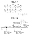
- step S4 if the distance for which the self-vehicle has been traveled during the time difference ⁇ t is longer than the half of the radius r of the GPS error circle R (step S4: YES), then, the corrected electric-wave-based measurement position after the correction is calculated by adding the travel distance during the time difference ⁇ t, which is calculated on the basis of the data from the self-sustained type sensors, onto the electric-wave-based measurement position based on the GPS measurement data (step S5). In the process at the step S5, as shown in FIG.
- the electric-wave-based measurement position P 0 which is measured on the basis of the electric waves at a time t 1 , is corrected forward by a distance ⁇ 1 for which the self vehicle has been traveled during the time difference ⁇ t between the time t 1 and a time t 2 , at which the self-sustained measurement position Ps is calculated, so that the corrected electric-wave-based measurement position P 1 is calculated, for example.
- step S6 the positions of the corrected electric-wave-based measurement position P 1 and the self-sustained measurement position Ps are compared with each other, and the self-sustained measurement position Ps is corrected by use of the corrected electric-wave-based measurement value P 1 , to calculate the present position of the self vehicle (step S6).
- a position on a road which has been calculated by a previous map matching process (hereinbelow, which is referred to as a "previously map matched position") is obtained from the RAM 8 (step S7).
- the present position of the self vehicle calculated at the step S6 is added to the previous map matched position as a moving vector (step S8), and the present position of the self vehicle is displayed as a present position mark of the self vehicle on the display 16 (step S9).
- the map matching process is performed with respect to the present position of the self vehicle (step S10), and the present position mark is re-displayed to be positioned as a map matched position on a road or the like, where the self vehicle should actually exist on the display 16. Then, the operation flow returns to the main navigation program.
- the present position of the self vehicle on the display 16 (which corresponds to a position P D in FIG. 3B), which is obtained in a case where the present position of the self vehicle calculated at the step S6 is added as the moving vector V ( ⁇ x, ⁇ y) onto the previous map matched position P MO , may be shifted from a road RD, on which the self vehicle should actually exist, at the stage of the step S7 since the map matching process has not been performed yet at this stage.
- the shift from the road RD is equivalent to a shift of the present position of the self vehicle calculated at the step S6 on the basis of the self-sustained measurement position, which is calculated from the data from the self-sustained type sensors once every second. That is to say, this shift is supposed to be within the range for which the self vehicle travels in just one second. Therefore, this shift is so small that the present position P D cannot be differentiated on the actual display 16 from a true present position C where the self vehicle is actually positioned on the road RD, due to the accuracy of the self-sustained type sensors or the like.
- step S9 the pertinent present position of the self vehicle is displayed as the present position mark on the display 16
- step S10 the map matching process is performed (step S10), so that the display position of the present position mark on the display 16 is corrected and the standard point for the calculation of the moving vector V for the next timing is calculated (step S11).
- the present position mark is corrected to be the map matched position on the road where the self vehicle should be actually exist on the display 16.
- the present embodiment may be constructed such that, after the map matching process is performed at the step S10, only the process of obtaining the standard point for the calculation of the moving vector V at the next timing is performed without displaying the map matched position.
- the time difference ⁇ t between the time for the electric-wave-based measurement and the time at receiving the data from the self-sustained type sensors is calculated.
- the corrected electric-wave-based measurement position is obtained by correcting the electric-wave-based measurement position i.e., the present position measured on the basis of only the GPS measurement data, on the basis of the calculated time difference ⁇ t.
- the present position of the self vehicle is calculated by correcting the self-sustained measurement position i.e., the present position measured on the basis of only the data from the self-sustained type sensors, by use of the corrected electric-wave-based measurement position.
- the corrected electric-wave-based measurement position is calculated by superimposing the moving distance ⁇ 1, which corresponds to the time difference ⁇ t of the self vehicle calculated on the basis of the data from the self-sustained type sensors, onto the electric-wave-based measurement position, the accurate present position can be calculated by use of a relatively simple process.
- the present position is displayed, which is obtained by correcting the present position based on the data from the self-sustained type sensors by use of the corrected electric-wave-based measurement position
- the displayed present position is corrected by use of the map matching process onto the road RD. Therefore, as compared with a case where the present position is displayed after executing the map matching process for correcting the present position onto the road RD, the present position can be displayed without including a moving error due to the time required for the map matching process according to the present embodiment.
- the correction process to achieve the time synchronization is executed only when the distance for which the self vehicle has been traveled during the time difference ⁇ t is longer than the half of the radius r of the GPS error circle R.
- the time synchronization matching process same as the first embodiment may be executed when each of predetermined conditions as for the speed v of the self vehicle, the radius r of the GPS error circle R and the time difference ⁇ t is satisfied independently.
- the same steps as those in FIG. 2 carry the same step numbers and the explanations thereof are omitted.
- step S3 the time difference ⁇ t is calculated (step S3).
- step S22 the correction process to achieve the time synchronization at and after the step S5 is performed.
- the predetermined speed value as a threshold for the speed v of the self vehicle at the step S20, 60 km/h may be adopted.
- the predetermined length value as a threshold for the radius r of the GPS error circle R at the step S21 50 m may be adopted.
- the predetermined time value as a threshold for the time difference ⁇ t at the step S22 3 seconds may be adopted.
- distance data 31 as substantial data of the travel distance data 30, and ID data 32 as identification data to identify the travel distance data 30 at each cycle are included as shown in FIG. 5C.
- one number among numbers from “0" to "255” is written in each ID data 32 in case that the ID data 32 is constructed as 1 byte data, for example.
- each of one travel distance data 30 and another travel distance data 30 continuous to it has the ID data 32 in which a number continuous to each other is written.
- a drop-out of the travel distance data 30 is detected by monitoring the ID data 32.
- a process for interpolating the dropped out travel distance data 30 is executed by use of another pieces of the travel distance data 30 before and after the dropped out travel distance data 30.
- the travel distance data 30 from the travel distance sensor 2 is received by the CPU 6 (step S30).
- step S31 the monitoring process for the ID data 32 of each travel distance data 30 is started, so that it is judged whether or not the ID data 32 of the presently received travel distance data 30 is continuous to that of the previously received travel distance data 30, which is supposed to be continuous in a normal situation. Then, if the ID data is judged to be continuous (step S31: YES), the distance data 31 in the received travel distance data 30 is accumulated as it is, so that the travel distance is calculated and the present position is calculated (step S33). After that, the calculated present position is outputted to the display unit 12 or the like (step S34), and the operation flow returns to the main navigation program.
- step S31 if the drop out of the travel distance data 30 is detected on the basis of the ID data 32 i.e., the ID data 32 is not continuous (step S31: NO), the process for interpolating the dropped out travel distance data 30 is performed by use of two pieces of the travel distance data 30 which are received before and after the dropped out travel distance data 30 (step S32).
- FIG. 5B shows a case where just one travel distance data 30 is dropped out.
- the distance data 31 of the travel distance data 30 before the dropped out travel distance data 30 is distance data Dn-1
- the distance data 31 of the travel distance data 30 after the dropped out travel distance data 30 is distance data Dn+1.
- the distance ⁇ dn-1 indicated by the distance data Dn-1 and the distance ⁇ dn+1 indicated by the distance data Dn+1 are added together.
- step S31 if the drop out of the travel distance data 30 is detected on the basis of the discontinuity of the ID data 32 (step S31: NO), at first the distance ⁇ dn-1 indicated by the distance data Dn-1 and the distance ⁇ dn+1 indicated by the distance data Dn+1 are added together. Then, the average of distance ⁇ dn-1 and the distance ⁇ dn+1 [i.e., ( ⁇ dn-1 + ⁇ dn+1) / 2 ] is calculated, and is added to the distance ⁇ dn+1, so that the interpolated distance ⁇ dn+1' is calculated (step S32). Namely, this interpolated distance ⁇ dn+1' indicates the distance in consideration of the distance indicated by the distance data 31 included in the dropped out travel distance data 30.
- step S33 the distance data 31 of the subsequent travel distance data 30 is accumulated with respect to this interpolated distance ⁇ dn+1', so that the travel distance is calculated and the present position is calculated (step S33). Then, this calculated present position is outputted to the display unit 12 or the like (step S34), and the operation flow returns to the main navigation program.
- the drop out of the travel distance data 30 is detected on the basis of the ID data 32 of the outputted travel distance data 30. And that, when the drop out is detected, the average of the distances indicated by two pieces of the travel distance data 30 outputted before and after the dropped out travel distance data 30 is calculated, so as to interpolate the distance indicated by the distance data 31 included in the dropped out travel distance data 30 on the basis of the two pieces of the travel distance data 30 outputted before and after the dropped out travel distance data 30, and the travel distance is calculate by use of the calculated average distance.
- the travel distance can be calculated by approximately interpolating it by the average distance, and the accurate present position of the self vehicle can be calculated.
- the present invention can be adapted. For example, in case that three consecutive pieces of the travel distance data 30 are dropped out, the average of the distances indicated by two pieces of the distance data 31 included in two pieces of the travel distance data 30 before and after the dropped out travel distance data 30 is calculated, and the calculated average is multiplied by 3 and then is accumulated, so that the dropped out travel distance data 30 can be approximately interpolated.
- the dropped out travel distance data 30 may be interpolated even more accurately, by differentiating the distance indicated by the distance data 31 included in the travel distance data 30 within a predetermine range before and after the dropped out travel distance data 30, by recognizing the tendency of the distance change of the travel distance data 30 before and after the dropped out, and by calculating the distance for interpolation in line with this recognized tendency.
- the present invention is not limited to this. Instead, the present invention can be adapted for other types of movable bodies such as an auto-cycle, auto-tricycle and so on.
Landscapes
- Engineering & Computer Science (AREA)
- Radar, Positioning & Navigation (AREA)
- Remote Sensing (AREA)
- Physics & Mathematics (AREA)
- General Physics & Mathematics (AREA)
- Computer Networks & Wireless Communication (AREA)
- Automation & Control Theory (AREA)
- Navigation (AREA)
- Position Fixing By Use Of Radio Waves (AREA)
- Traffic Control Systems (AREA)
- Instructional Devices (AREA)
- Measurement Of Distances Traversed On The Ground (AREA)
Applications Claiming Priority (3)
| Application Number | Priority Date | Filing Date | Title |
|---|---|---|---|
| JP8111706A JPH09297030A (ja) | 1996-05-02 | 1996-05-02 | 移動体位置算出方法及び装置並びに移動体位置補正方法及び装置 |
| JP11170696 | 1996-05-02 | ||
| EP97107324A EP0805358B1 (fr) | 1996-05-02 | 1997-05-02 | Procédé et dispositif pour calculer et corriger la position d'un mobile dans un système de navigation |
Related Parent Applications (2)
| Application Number | Title | Priority Date | Filing Date |
|---|---|---|---|
| EP97107324A Division EP0805358B1 (fr) | 1996-05-02 | 1997-05-02 | Procédé et dispositif pour calculer et corriger la position d'un mobile dans un système de navigation |
| EP97107324A Division-Into EP0805358B1 (fr) | 1996-05-02 | 1997-05-02 | Procédé et dispositif pour calculer et corriger la position d'un mobile dans un système de navigation |
Publications (2)
| Publication Number | Publication Date |
|---|---|
| EP1178329A1 true EP1178329A1 (fr) | 2002-02-06 |
| EP1178329B1 EP1178329B1 (fr) | 2006-02-01 |
Family
ID=14568098
Family Applications (2)
| Application Number | Title | Priority Date | Filing Date |
|---|---|---|---|
| EP97107324A Expired - Lifetime EP0805358B1 (fr) | 1996-05-02 | 1997-05-02 | Procédé et dispositif pour calculer et corriger la position d'un mobile dans un système de navigation |
| EP01121937A Expired - Lifetime EP1178329B1 (fr) | 1996-05-02 | 1997-05-02 | Appareil et méthode de correction de la position d'un corps mobile dans un système de navigation |
Family Applications Before (1)
| Application Number | Title | Priority Date | Filing Date |
|---|---|---|---|
| EP97107324A Expired - Lifetime EP0805358B1 (fr) | 1996-05-02 | 1997-05-02 | Procédé et dispositif pour calculer et corriger la position d'un mobile dans un système de navigation |
Country Status (4)
| Country | Link |
|---|---|
| US (1) | US5949375A (fr) |
| EP (2) | EP0805358B1 (fr) |
| JP (1) | JPH09297030A (fr) |
| DE (2) | DE69735172T2 (fr) |
Families Citing this family (41)
| Publication number | Priority date | Publication date | Assignee | Title |
|---|---|---|---|---|
| FR2752984B1 (fr) * | 1996-09-03 | 1998-11-27 | Sextant Avionique | Procede d'aide a la navigation d'un mobile vers une cible egalement mobile |
| US6115668A (en) * | 1997-03-07 | 2000-09-05 | Pioneer Electronic Corporation | Navigation apparatus for detecting a present position of a moveable body |
| JP3449240B2 (ja) | 1998-09-24 | 2003-09-22 | 株式会社デンソー | 車両用現在位置検出装置、車両用現在位置表示装置、ナビゲーション装置および記録媒体 |
| JP2000194726A (ja) | 1998-10-19 | 2000-07-14 | Sony Corp | 情報処理装置及び方法、情報処理システム並びに提供媒体 |
| US7739167B2 (en) | 1999-03-05 | 2010-06-15 | Era Systems Corporation | Automated management of airport revenues |
| US7777675B2 (en) | 1999-03-05 | 2010-08-17 | Era Systems Corporation | Deployable passive broadband aircraft tracking |
| US8203486B1 (en) | 1999-03-05 | 2012-06-19 | Omnipol A.S. | Transmitter independent techniques to extend the performance of passive coherent location |
| US7570214B2 (en) | 1999-03-05 | 2009-08-04 | Era Systems, Inc. | Method and apparatus for ADS-B validation, active and passive multilateration, and elliptical surviellance |
| US8446321B2 (en) | 1999-03-05 | 2013-05-21 | Omnipol A.S. | Deployable intelligence and tracking system for homeland security and search and rescue |
| US7782256B2 (en) | 1999-03-05 | 2010-08-24 | Era Systems Corporation | Enhanced passive coherent location techniques to track and identify UAVs, UCAVs, MAVs, and other objects |
| US7889133B2 (en) | 1999-03-05 | 2011-02-15 | Itt Manufacturing Enterprises, Inc. | Multilateration enhancements for noise and operations management |
| US7667647B2 (en) | 1999-03-05 | 2010-02-23 | Era Systems Corporation | Extension of aircraft tracking and positive identification from movement areas into non-movement areas |
| US7908077B2 (en) | 2003-06-10 | 2011-03-15 | Itt Manufacturing Enterprises, Inc. | Land use compatibility planning software |
| JP2000329570A (ja) * | 1999-05-17 | 2000-11-30 | Clarion Co Ltd | 移動体用衛星測位装置及びカーナビゲーションシステム |
| JP2002333452A (ja) | 2001-05-07 | 2002-11-22 | Pioneer Electronic Corp | 車速パルス抜け検出方法及び装置、車載用ナビゲーションシステム及びコンピュータプログラム |
| JP4402318B2 (ja) | 2001-05-08 | 2010-01-20 | パイオニア株式会社 | ナビゲーション装置 |
| AU2002346211B2 (en) | 2001-06-27 | 2008-06-12 | Sony Corporation | Integrated circuit device, information processing device, information recording device memory management method, mobile terminal device, semiconductor integrated circuit device, and communication method using mobile terminal device |
| US20050107929A1 (en) * | 2001-09-01 | 2005-05-19 | Bayerische Motoren Werke Ag | Method, device and computer product for updating data of a control device |
| US7038619B2 (en) | 2001-12-31 | 2006-05-02 | Rdp Associates, Incorporated | Satellite positioning system enabled media measurement system and method |
| AU2005267688A1 (en) * | 2004-07-30 | 2006-02-09 | Nielson Media Research, Inc. | Methods and apparatus for improving the accuracy and reach of electronic media exposure measurement systems |
| EP1779125A4 (fr) * | 2004-07-30 | 2009-12-16 | Nielsen Media Res Inc | Procedes et appareil pour l'amelioration de la precision et de la portee de systemes de mesures electroniques d'exposition aux medias |
| KR101047719B1 (ko) * | 2005-02-16 | 2011-07-08 | 엘지전자 주식회사 | 네비게이션 시스템에서 이동체의 주행경로 안내방법 및 장치 |
| JP2007024832A (ja) * | 2005-07-21 | 2007-02-01 | Seiko Epson Corp | 端末装置、端末装置の制御方法、端末装置の制御プログラム、端末装置の制御プログラムを記録したコンピュータ読み取り可能な記録媒体 |
| JP4352031B2 (ja) * | 2005-08-01 | 2009-10-28 | 株式会社ナビタイムジャパン | ナビゲーションシステム、端末装置および地図表示方法 |
| JP4655901B2 (ja) * | 2005-11-21 | 2011-03-23 | パナソニック株式会社 | 移動体の水平走行判定装置及び方法 |
| US7965227B2 (en) | 2006-05-08 | 2011-06-21 | Era Systems, Inc. | Aircraft tracking using low cost tagging as a discriminator |
| JP4858197B2 (ja) * | 2007-01-31 | 2012-01-18 | ソニー株式会社 | 情報処理装置、画像表示装置、情報処理システム、情報処理方法およびプログラム |
| WO2008157482A1 (fr) * | 2007-06-15 | 2008-12-24 | Cadec Global, Inc. | Système et procédé permettant de prédire le retournement d'un véhicule en utilisant le suivi de position |
| US9852624B2 (en) | 2007-09-07 | 2017-12-26 | Connected Signals, Inc. | Network security system with application for driver safety system |
| US20130131980A1 (en) * | 2007-09-07 | 2013-05-23 | On Time Systems, Inc. | Resolving gps ambiguity in electronic maps |
| US9043138B2 (en) | 2007-09-07 | 2015-05-26 | Green Driver, Inc. | System and method for automated updating of map information |
| US10083607B2 (en) | 2007-09-07 | 2018-09-25 | Green Driver, Inc. | Driver safety enhancement using intelligent traffic signals and GPS |
| JP5192931B2 (ja) * | 2008-07-22 | 2013-05-08 | パイオニア株式会社 | 移動体情報表示装置及び移動体情報表示方法等 |
| US10198942B2 (en) | 2009-08-11 | 2019-02-05 | Connected Signals, Inc. | Traffic routing display system with multiple signal lookahead |
| JP5943724B2 (ja) * | 2012-06-08 | 2016-07-05 | 株式会社日立アドバンストシステムズ | 情報処理システム、及び屋内外のシームレスな軌跡を生成する方法 |
| FR3019361B1 (fr) * | 2014-03-28 | 2017-05-19 | Airbus Helicopters | Procede de detection et de visualisation des obstacles artificiels d'un aeronef a voilure tournante |
| WO2017082388A1 (fr) * | 2015-11-11 | 2017-05-18 | パイオニア株式会社 | Dispositif de sécurité, procédé de commande de sécurité, programme et support d'informations |
| JP6424845B2 (ja) * | 2016-02-03 | 2018-11-21 | 株式会社デンソー | 位置補正装置、ナビゲーションシステム、及び自動運転システム |
| US10969228B2 (en) * | 2018-06-05 | 2021-04-06 | Novatel Inc. | Relative position navigation system for multiple moving vehicles |
| JP7275520B2 (ja) * | 2018-10-03 | 2023-05-18 | 株式会社アイシン | 車両制御装置 |
| CN113740800A (zh) * | 2020-05-28 | 2021-12-03 | 南宁富桂精密工业有限公司 | 行车定位系统及行车定位方法 |
Citations (2)
| Publication number | Priority date | Publication date | Assignee | Title |
|---|---|---|---|---|
| WO1994027265A1 (fr) * | 1993-05-06 | 1994-11-24 | Spectronics Micro Systems Limited | Ameliorations apportees a des systemes automatiques indiquant la position de vehicules |
| US5390124A (en) * | 1992-12-01 | 1995-02-14 | Caterpillar Inc. | Method and apparatus for improving the accuracy of position estimates in a satellite based navigation system |
Family Cites Families (9)
| Publication number | Priority date | Publication date | Assignee | Title |
|---|---|---|---|---|
| JPS62298717A (ja) * | 1986-06-19 | 1987-12-25 | Nissan Motor Co Ltd | Gps位置計測装置 |
| KR910004416B1 (ko) * | 1987-03-13 | 1991-06-27 | 미쓰비시덴기 가부시기가이샤 | 차량 탑재형 내비게이터 장치 |
| JPH0792500B2 (ja) * | 1991-05-31 | 1995-10-09 | 住友電気工業株式会社 | Gps測位方式を利用した位置検出装置 |
| JP3267310B2 (ja) * | 1991-07-10 | 2002-03-18 | パイオニア株式会社 | Gpsナビゲーション装置 |
| DE4211933A1 (de) * | 1992-04-09 | 1993-10-14 | Philips Patentverwaltung | Anordnung zur Positionsbestimmung eines Landfahrzeugs |
| JPH06148307A (ja) * | 1992-11-04 | 1994-05-27 | Pioneer Electron Corp | ナビゲーション装置 |
| DE4332945A1 (de) * | 1993-09-28 | 1995-03-30 | Bosch Gmbh Robert | Ortungs- und Navigationsgerät mit Satellitenstützung |
| DE69526011T2 (de) * | 1994-09-01 | 2002-08-01 | Aisin Aw Co | Navigationssystem |
| JPH095092A (ja) * | 1995-06-16 | 1997-01-10 | Maspro Denkoh Corp | 移動体位置検出装置 |
-
1996
- 1996-05-02 JP JP8111706A patent/JPH09297030A/ja active Pending
-
1997
- 1997-04-30 US US08/841,102 patent/US5949375A/en not_active Expired - Fee Related
- 1997-05-02 EP EP97107324A patent/EP0805358B1/fr not_active Expired - Lifetime
- 1997-05-02 EP EP01121937A patent/EP1178329B1/fr not_active Expired - Lifetime
- 1997-05-02 DE DE69735172T patent/DE69735172T2/de not_active Expired - Fee Related
- 1997-05-02 DE DE69732063T patent/DE69732063T2/de not_active Expired - Fee Related
Patent Citations (2)
| Publication number | Priority date | Publication date | Assignee | Title |
|---|---|---|---|---|
| US5390124A (en) * | 1992-12-01 | 1995-02-14 | Caterpillar Inc. | Method and apparatus for improving the accuracy of position estimates in a satellite based navigation system |
| WO1994027265A1 (fr) * | 1993-05-06 | 1994-11-24 | Spectronics Micro Systems Limited | Ameliorations apportees a des systemes automatiques indiquant la position de vehicules |
Non-Patent Citations (1)
| Title |
|---|
| WEI-WEN KAO: "INTEGRATION OF GPS AND DEAD-RECKONING NAVIGATION SYSTEMS", PROCEEDINGS OF THE VEHICLE NAVIGATION AND INFORMATION SYSTEMS CONFERENCE. DEARBORN, OCT. 20 - 23, 1991, NEW YORK, IEEE, US, vol. 2, 20 October 1991 (1991-10-20), pages 635 - 643, XP000357137, ISBN: 0-7803-0488-8 * |
Also Published As
| Publication number | Publication date |
|---|---|
| DE69735172T2 (de) | 2006-10-19 |
| EP0805358A3 (fr) | 1998-06-17 |
| EP0805358A2 (fr) | 1997-11-05 |
| DE69732063T2 (de) | 2005-12-08 |
| JPH09297030A (ja) | 1997-11-18 |
| DE69735172D1 (de) | 2006-04-13 |
| US5949375A (en) | 1999-09-07 |
| DE69732063D1 (de) | 2005-02-03 |
| EP1178329B1 (fr) | 2006-02-01 |
| EP0805358B1 (fr) | 2004-12-29 |
Similar Documents
| Publication | Publication Date | Title |
|---|---|---|
| EP0805358B1 (fr) | Procédé et dispositif pour calculer et corriger la position d'un mobile dans un système de navigation | |
| EP0629840B1 (fr) | Système de navigation | |
| EP0805336B1 (fr) | Méthode et appareil pour l'entrée de routes dans un système de navigation | |
| EP0519630B1 (fr) | Appareil pour la détermination d'une position | |
| EP0699894B1 (fr) | Systéme de navigation | |
| JP3243236B2 (ja) | 位置データ間引き装置 | |
| EP0738877B1 (fr) | Système pour la correction d'un odomètre d'un véhicule | |
| US5657231A (en) | Route setting method and route setting apparatus in navigation system, and navigation system | |
| JP3449240B2 (ja) | 車両用現在位置検出装置、車両用現在位置表示装置、ナビゲーション装置および記録媒体 | |
| US5442559A (en) | Navigation apparatus | |
| EP0747668B1 (fr) | Système pour calculer la position réelle pour véhicule ayant une fonction pour corriger une direction de véhicule | |
| US5583775A (en) | Navigation apparatus and navigation method | |
| JPH08313278A (ja) | 測位データ補正装置及び測位データ補正方法 | |
| JP3983849B2 (ja) | ナビゲーション装置 | |
| EP1357354B1 (fr) | Détermination de l'état de mouvement | |
| US6070122A (en) | Vehicle navigation with priority target display | |
| JP4316820B2 (ja) | 車載ナビゲーション装置及び方位測定方法 | |
| EP0601712A1 (fr) | Système de navigation | |
| JPH06331375A (ja) | 移動体測位装置およびカーナビゲーション装置 | |
| JP3126751B2 (ja) | 距離補正係数の自動補正装置 | |
| KR100518850B1 (ko) | 실시간 주행정보 보정 차량 항법시스템 및 그 방법 | |
| JP2703588B2 (ja) | 車両用ナビゲーション装置 | |
| JPH08327377A (ja) | ナビゲーション装置 | |
| JPH08327376A (ja) | ナビゲーション装置 | |
| JPH06109827A (ja) | 位置検出装置 |
Legal Events
| Date | Code | Title | Description |
|---|---|---|---|
| PUAI | Public reference made under article 153(3) epc to a published international application that has entered the european phase |
Free format text: ORIGINAL CODE: 0009012 |
|
| AC | Divisional application: reference to earlier application |
Ref document number: 805358 Country of ref document: EP |
|
| AK | Designated contracting states |
Kind code of ref document: A1 Designated state(s): DE FR GB |
|
| 17P | Request for examination filed |
Effective date: 20020806 |
|
| AKX | Designation fees paid |
Free format text: DE FR GB |
|
| 17Q | First examination report despatched |
Effective date: 20030220 |
|
| GRAP | Despatch of communication of intention to grant a patent |
Free format text: ORIGINAL CODE: EPIDOSNIGR1 |
|
| GRAS | Grant fee paid |
Free format text: ORIGINAL CODE: EPIDOSNIGR3 |
|
| GRAA | (expected) grant |
Free format text: ORIGINAL CODE: 0009210 |
|
| AC | Divisional application: reference to earlier application |
Ref document number: 0805358 Country of ref document: EP Kind code of ref document: P |
|
| AK | Designated contracting states |
Kind code of ref document: B1 Designated state(s): DE FR GB |
|
| REG | Reference to a national code |
Ref country code: GB Ref legal event code: FG4D |
|
| REF | Corresponds to: |
Ref document number: 69735172 Country of ref document: DE Date of ref document: 20060413 Kind code of ref document: P |
|
| REG | Reference to a national code |
Ref country code: GB Ref legal event code: 746 Effective date: 20060328 |
|
| ET | Fr: translation filed | ||
| PLBE | No opposition filed within time limit |
Free format text: ORIGINAL CODE: 0009261 |
|
| STAA | Information on the status of an ep patent application or granted ep patent |
Free format text: STATUS: NO OPPOSITION FILED WITHIN TIME LIMIT |
|
| 26N | No opposition filed |
Effective date: 20061103 |
|
| PGFP | Annual fee paid to national office [announced via postgrant information from national office to epo] |
Ref country code: DE Payment date: 20070531 Year of fee payment: 11 |
|
| PGFP | Annual fee paid to national office [announced via postgrant information from national office to epo] |
Ref country code: GB Payment date: 20070523 Year of fee payment: 11 |
|
| PGFP | Annual fee paid to national office [announced via postgrant information from national office to epo] |
Ref country code: FR Payment date: 20070518 Year of fee payment: 11 |
|
| GBPC | Gb: european patent ceased through non-payment of renewal fee |
Effective date: 20080502 |
|
| REG | Reference to a national code |
Ref country code: FR Ref legal event code: ST Effective date: 20090119 |
|
| PG25 | Lapsed in a contracting state [announced via postgrant information from national office to epo] |
Ref country code: FR Free format text: LAPSE BECAUSE OF NON-PAYMENT OF DUE FEES Effective date: 20080602 Ref country code: DE Free format text: LAPSE BECAUSE OF NON-PAYMENT OF DUE FEES Effective date: 20081202 |
|
| PG25 | Lapsed in a contracting state [announced via postgrant information from national office to epo] |
Ref country code: GB Free format text: LAPSE BECAUSE OF NON-PAYMENT OF DUE FEES Effective date: 20080502 |