EP1147032B1 - Device for monitoring the surrounding area of a vehicle during parking - Google Patents
Device for monitoring the surrounding area of a vehicle during parking Download PDFInfo
- Publication number
- EP1147032B1 EP1147032B1 EP00982930A EP00982930A EP1147032B1 EP 1147032 B1 EP1147032 B1 EP 1147032B1 EP 00982930 A EP00982930 A EP 00982930A EP 00982930 A EP00982930 A EP 00982930A EP 1147032 B1 EP1147032 B1 EP 1147032B1
- Authority
- EP
- European Patent Office
- Prior art keywords
- unit
- vehicle
- manoeuvre
- object detection
- objects
- Prior art date
- Legal status (The legal status is an assumption and is not a legal conclusion. Google has not performed a legal analysis and makes no representation as to the accuracy of the status listed.)
- Expired - Lifetime
Links
- 238000012544 monitoring process Methods 0.000 title claims abstract description 9
- 238000004364 calculation method Methods 0.000 claims abstract description 13
- 238000001514 detection method Methods 0.000 claims description 16
- 238000012545 processing Methods 0.000 claims description 11
- 230000008901 benefit Effects 0.000 description 5
- 238000000034 method Methods 0.000 description 4
- 230000000007 visual effect Effects 0.000 description 3
- 230000001419 dependent effect Effects 0.000 description 2
- 230000008569 process Effects 0.000 description 2
- 230000001154 acute effect Effects 0.000 description 1
- 238000013459 approach Methods 0.000 description 1
- 238000004891 communication Methods 0.000 description 1
- 238000012937 correction Methods 0.000 description 1
- 230000008878 coupling Effects 0.000 description 1
- 238000010168 coupling process Methods 0.000 description 1
- 238000005859 coupling reaction Methods 0.000 description 1
- 230000007613 environmental effect Effects 0.000 description 1
- 238000011156 evaluation Methods 0.000 description 1
- 230000006870 function Effects 0.000 description 1
- 230000003287 optical effect Effects 0.000 description 1
- 230000009467 reduction Effects 0.000 description 1
- 210000002023 somite Anatomy 0.000 description 1
- 230000002123 temporal effect Effects 0.000 description 1
- 238000002604 ultrasonography Methods 0.000 description 1
Images


Classifications
-
- B—PERFORMING OPERATIONS; TRANSPORTING
- B60—VEHICLES IN GENERAL
- B60R—VEHICLES, VEHICLE FITTINGS, OR VEHICLE PARTS, NOT OTHERWISE PROVIDED FOR
- B60R1/00—Optical viewing arrangements; Real-time viewing arrangements for drivers or passengers using optical image capturing systems, e.g. cameras or video systems specially adapted for use in or on vehicles
- B60R1/20—Real-time viewing arrangements for drivers or passengers using optical image capturing systems, e.g. cameras or video systems specially adapted for use in or on vehicles
- B60R1/22—Real-time viewing arrangements for drivers or passengers using optical image capturing systems, e.g. cameras or video systems specially adapted for use in or on vehicles for viewing an area outside the vehicle, e.g. the exterior of the vehicle
- B60R1/23—Real-time viewing arrangements for drivers or passengers using optical image capturing systems, e.g. cameras or video systems specially adapted for use in or on vehicles for viewing an area outside the vehicle, e.g. the exterior of the vehicle with a predetermined field of view
-
- B—PERFORMING OPERATIONS; TRANSPORTING
- B60—VEHICLES IN GENERAL
- B60Q—ARRANGEMENT OF SIGNALLING OR LIGHTING DEVICES, THE MOUNTING OR SUPPORTING THEREOF OR CIRCUITS THEREFOR, FOR VEHICLES IN GENERAL
- B60Q9/00—Arrangement or adaptation of signal devices not provided for in one of main groups B60Q1/00 - B60Q7/00, e.g. haptic signalling
- B60Q9/002—Arrangement or adaptation of signal devices not provided for in one of main groups B60Q1/00 - B60Q7/00, e.g. haptic signalling for parking purposes, e.g. for warning the driver that his vehicle has contacted or is about to contact an obstacle
- B60Q9/004—Arrangement or adaptation of signal devices not provided for in one of main groups B60Q1/00 - B60Q7/00, e.g. haptic signalling for parking purposes, e.g. for warning the driver that his vehicle has contacted or is about to contact an obstacle using wave sensors
- B60Q9/005—Arrangement or adaptation of signal devices not provided for in one of main groups B60Q1/00 - B60Q7/00, e.g. haptic signalling for parking purposes, e.g. for warning the driver that his vehicle has contacted or is about to contact an obstacle using wave sensors using a video camera
-
- B—PERFORMING OPERATIONS; TRANSPORTING
- B60—VEHICLES IN GENERAL
- B60Q—ARRANGEMENT OF SIGNALLING OR LIGHTING DEVICES, THE MOUNTING OR SUPPORTING THEREOF OR CIRCUITS THEREFOR, FOR VEHICLES IN GENERAL
- B60Q9/00—Arrangement or adaptation of signal devices not provided for in one of main groups B60Q1/00 - B60Q7/00, e.g. haptic signalling
- B60Q9/002—Arrangement or adaptation of signal devices not provided for in one of main groups B60Q1/00 - B60Q7/00, e.g. haptic signalling for parking purposes, e.g. for warning the driver that his vehicle has contacted or is about to contact an obstacle
- B60Q9/007—Arrangement or adaptation of signal devices not provided for in one of main groups B60Q1/00 - B60Q7/00, e.g. haptic signalling for parking purposes, e.g. for warning the driver that his vehicle has contacted or is about to contact an obstacle providing information about the distance to an obstacle, e.g. varying sound
-
- B—PERFORMING OPERATIONS; TRANSPORTING
- B60—VEHICLES IN GENERAL
- B60R—VEHICLES, VEHICLE FITTINGS, OR VEHICLE PARTS, NOT OTHERWISE PROVIDED FOR
- B60R1/00—Optical viewing arrangements; Real-time viewing arrangements for drivers or passengers using optical image capturing systems, e.g. cameras or video systems specially adapted for use in or on vehicles
- B60R1/20—Real-time viewing arrangements for drivers or passengers using optical image capturing systems, e.g. cameras or video systems specially adapted for use in or on vehicles
- B60R1/22—Real-time viewing arrangements for drivers or passengers using optical image capturing systems, e.g. cameras or video systems specially adapted for use in or on vehicles for viewing an area outside the vehicle, e.g. the exterior of the vehicle
- B60R1/28—Real-time viewing arrangements for drivers or passengers using optical image capturing systems, e.g. cameras or video systems specially adapted for use in or on vehicles for viewing an area outside the vehicle, e.g. the exterior of the vehicle with an adjustable field of view
-
- B—PERFORMING OPERATIONS; TRANSPORTING
- B60—VEHICLES IN GENERAL
- B60R—VEHICLES, VEHICLE FITTINGS, OR VEHICLE PARTS, NOT OTHERWISE PROVIDED FOR
- B60R2300/00—Details of viewing arrangements using cameras and displays, specially adapted for use in a vehicle
- B60R2300/10—Details of viewing arrangements using cameras and displays, specially adapted for use in a vehicle characterised by the type of camera system used
- B60R2300/105—Details of viewing arrangements using cameras and displays, specially adapted for use in a vehicle characterised by the type of camera system used using multiple cameras
-
- B—PERFORMING OPERATIONS; TRANSPORTING
- B60—VEHICLES IN GENERAL
- B60R—VEHICLES, VEHICLE FITTINGS, OR VEHICLE PARTS, NOT OTHERWISE PROVIDED FOR
- B60R2300/00—Details of viewing arrangements using cameras and displays, specially adapted for use in a vehicle
- B60R2300/30—Details of viewing arrangements using cameras and displays, specially adapted for use in a vehicle characterised by the type of image processing
- B60R2300/301—Details of viewing arrangements using cameras and displays, specially adapted for use in a vehicle characterised by the type of image processing combining image information with other obstacle sensor information, e.g. using RADAR/LIDAR/SONAR sensors for estimating risk of collision
-
- B—PERFORMING OPERATIONS; TRANSPORTING
- B60—VEHICLES IN GENERAL
- B60R—VEHICLES, VEHICLE FITTINGS, OR VEHICLE PARTS, NOT OTHERWISE PROVIDED FOR
- B60R2300/00—Details of viewing arrangements using cameras and displays, specially adapted for use in a vehicle
- B60R2300/30—Details of viewing arrangements using cameras and displays, specially adapted for use in a vehicle characterised by the type of image processing
- B60R2300/302—Details of viewing arrangements using cameras and displays, specially adapted for use in a vehicle characterised by the type of image processing combining image information with GPS information or vehicle data, e.g. vehicle speed, gyro, steering angle data
-
- B—PERFORMING OPERATIONS; TRANSPORTING
- B60—VEHICLES IN GENERAL
- B60R—VEHICLES, VEHICLE FITTINGS, OR VEHICLE PARTS, NOT OTHERWISE PROVIDED FOR
- B60R2300/00—Details of viewing arrangements using cameras and displays, specially adapted for use in a vehicle
- B60R2300/70—Details of viewing arrangements using cameras and displays, specially adapted for use in a vehicle characterised by an event-triggered choice to display a specific image among a selection of captured images
-
- B—PERFORMING OPERATIONS; TRANSPORTING
- B60—VEHICLES IN GENERAL
- B60R—VEHICLES, VEHICLE FITTINGS, OR VEHICLE PARTS, NOT OTHERWISE PROVIDED FOR
- B60R2300/00—Details of viewing arrangements using cameras and displays, specially adapted for use in a vehicle
- B60R2300/80—Details of viewing arrangements using cameras and displays, specially adapted for use in a vehicle characterised by the intended use of the viewing arrangement
- B60R2300/802—Details of viewing arrangements using cameras and displays, specially adapted for use in a vehicle characterised by the intended use of the viewing arrangement for monitoring and displaying vehicle exterior blind spot views
-
- B—PERFORMING OPERATIONS; TRANSPORTING
- B60—VEHICLES IN GENERAL
- B60R—VEHICLES, VEHICLE FITTINGS, OR VEHICLE PARTS, NOT OTHERWISE PROVIDED FOR
- B60R2300/00—Details of viewing arrangements using cameras and displays, specially adapted for use in a vehicle
- B60R2300/80—Details of viewing arrangements using cameras and displays, specially adapted for use in a vehicle characterised by the intended use of the viewing arrangement
- B60R2300/806—Details of viewing arrangements using cameras and displays, specially adapted for use in a vehicle characterised by the intended use of the viewing arrangement for aiding parking
Definitions
- the invention relates to a device for monitoring the surroundings of a parking vehicle according to the preamble of the main claim. It is already such a device known from DE 43 36 288 C1, are provided in the expansion of the field of view of a camera means for pivoting this camera.
- the device according to the invention with the characterizing features of the main claim has the advantage over, by means of a simple, robust arrangement to ensure safe monitoring of the vehicle environment. Movable and thus susceptible parts are avoided and blind spots of the video camera included in the monitoring, so that the driver also receives a danger message, for example, in the blind spot of the camera people and not only when questionable obstacles are in the field of view of the camera.
- a danger message for example, in the blind spot of the camera people and not only when questionable obstacles are in the field of view of the camera.
- an object recognition unit which processes both data of the object recognition sensors and the video images for the evaluation of objects.
- the combination of multiple sensor information to a total display has the advantage that the system behavior is transparent at all times, as the driver can visually check the information.
- the driver is not limited to a few parameters, such as on the vehicle distance to the back of the person who would provide isolated object detection sensors instructed. As a result, a simple control and driving correction by the driver is possible at any time.
- the visual presentation of the results in the image of the receiving video camera has the advantage that the driver can very well accommodate the situation since he is accustomed to directing the vehicle based on visual information.
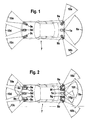
- Figure 1 shows a plan view of a vehicle 7.
- a video camera 1a is arranged, which receives the rear portion of the vehicle in a viewing area 8a.
- the video camera 1a adjacent object detection sensors 9a and 9b are mounted, which are used to detect objects in the surrounding sectors 10a and 10b.
- These environmental sensors 10a and 10b are immediately adjacent to the viewing area 8a, but are outside this viewing area.
- front-facing object recognition sensors 9c, 9d and 9e are arranged in the area of the front bumper of the motor vehicle, which monitor environment sectors 10c, 10d and 10e, which are oriented towards the front space.
- the video camera 1a which is permanently installed and immovable with minimal effort, covers a predetermined viewing area 8a, which can be displayed to the driver via a screen unit arranged, for example, in the dashboard or the center console of the vehicle.
- Object recognition sensors 9a and 9b can be seen in particular objects that approach the recorded area of the camera, but are not yet detected in the image. Such detected objects can then be reported to the driver, although they are not yet visible in the camera image. This is, for example, a child approaching the vehicle from the side, but the driver can not recognize this child either in the displayed image of the camera or in the rear-view mirrors, since it is in the blind spot.
- the object recognition sensors are designed, for example, as ultrasound, radar, video or lidar sensors.
- the additional sensors 9c, 9d and 9e can be used to measure the distance to the front parked vehicle at any time during parking maneuvers or to detect further (endangered) objects. If the distance to the front vehicle or other object is too small, a message can be issued.
- the additional sensors can also be installed anywhere in the vehicle to monitor the environment.
- the temporal vehicle area offers further attachment possibilities in which objects can be observed and corresponding warnings can be output to the driver. If the object recognition is carried out monocularly, cost savings result since only one camera is used.
- such methods have the disadvantage over stereo methods of not providing highly accurate and reliable results. Precisely because of the coupling of monocular object detection with other sensors, such as ultrasonic sensors, the accuracy and reliability can be increased considerably.
- FIG. 2 shows the vehicle 7 with additionally installed video cameras 1b and 1c, their associated viewing areas 8b or 8c cover the front of the vehicle.
- the cameras are mounted between the object recognition sensors 9c, 9d or 9e, so that the three mentioned object recognition sensors monitor the border areas of the viewing areas 8b and 8c in addition to the cameras.
- further object detection sensors 9f and 9g are mounted in the rear portion of the vehicle, with their respective surrounding sectors 10f and 10g partially overlapping with the viewing area 8a of the video camera 1a and thus monitoring those areas of the viewing area 8a in addition to the video camera.
- the provision of additional object recognition sensors in the rear vehicle part serves to increase the security in the object recognition by generating data redundancy. If the vehicle 7 is operated with a trailer, if the trailer obscures the rear view camera's or the rear sector object detection sensors, this trailer may be provided with an analogue observer 1a, 9a, 9b, 9f, 9g is aligned on the area behind the trailer. Thus, vehicles with trailer operation can assist the driver in a maneuvering maneuver.
- FIG 3 shows the schematic structure of a device for monitoring the surroundings of a parking vehicle, in which the entirety of the video cameras with reference numeral 1 and the entirety of the object recognition sensors with reference numeral 9 are designated.
- the video cameras and the object recognition sensors are connected to a control unit 20.
- the control unit 20 has an image processing unit 2 which processes the image data of the video cameras 1.
- the image processing unit 2 supplies rendered image data to an object recognition unit 30, which both the processed Image data of the video cameras as well as the signals of the object recognition sensors 9 processed.
- Via an acoustic display 6 detected objects or dangerous situations can be reported to the driver.
- the acoustic display is arranged in the passenger area of the vehicle.
- An overlay unit 40 is in communication with the image processing unit 2 and the object recognition unit 30.
- This overlay unit 40 overlays information provided by the object recognition unit 30 regarding detected objects with the edited image data of the image processing unit 2 for display in a display unit 55 or 55 '.
- the object recognition unit 30 is further connected to a maneuvering unit 50, which calculates driving maneuvers from the object data of the object recognition unit 30 and externally supplied parameters 4, for example the selected steering wheel angle, and forwards these data to the superimposition unit 40 for visual display in the screen unit.
- the maneuvering unit 50 is also connected to a control unit 90 for the automatic execution of a driving maneuver.
- FIG. 4 shows an embodiment 55 of the screen unit for displaying the images delivered by the cameras and processed by the control unit.
- the screen unit 55 has an image area 12 and both vertical edge areas 13 and horizontal edge areas 14, which together surround the image area 12.
- colored bars can be displayed for the optical reporting of objects in the vehicle environment that is not detected by the viewing area of the video camera (S).
- a pictogram 15 can be displayed at a suitable location for displaying the own vehicle. In the vicinity of this vehicle, the position of detected objects can also be drawn.
- the screen unit 55 may advantageously be integrated in the dashboard or in the center console of the vehicle.
- a signal color for example red
- red can be used in the edge regions. Whichever Beam lights up, the driver knows immediately which side of the vehicle he has to pay particular attention, although the camera image gives him no clues. Additional support can be provided in parallel by the acoustic display 6.
- FIG. 5 shows a further embodiment 55 'of the screen unit.
- a cube 115 is shown, which represents approximately a recognized object in its size and shape.
- data for the distance or the size of this object can be displayed.
- the lines 16 mark the driving path of the vehicle if the given steering angle were maintained.
- Lines 17 mark the route the vehicle would occupy if the driver followed the calculated route.
- FIG. 6 shows by way of example a parking maneuver of the vehicle 7 behind the parking vehicle 107 and in front of the parking vehicle 108.
- the same reference numerals as in the preceding figures denote the same parts and will not be described again.
- the laterally arranged object recognition sensors 9a and 9b detect areas which can not be observed by the fixed camera 8a, but are of relevance for parking, in particular when careless pedestrians enter the areas just outside the viewing area 8a of the camera 1a, for example.
- the driver receives a corresponding warning via the screen unit and can behave accordingly until these pedestrians move away from the blind spot of the vehicle.
- the front object recognition sensors 9 c, 9 d and 9 e provide the exact distance to the front vehicle 107 and simplify parking for him, especially in confusing vehicle bodies, which can only guess the limitations of the vehicle from the driver's seat.
Landscapes
- Engineering & Computer Science (AREA)
- Multimedia (AREA)
- Mechanical Engineering (AREA)
- Transportation (AREA)
- Human Computer Interaction (AREA)
- Radar, Positioning & Navigation (AREA)
- Remote Sensing (AREA)
- Traffic Control Systems (AREA)
- Closed-Circuit Television Systems (AREA)
Abstract
Description
Die Erfindung geht aus von einer Einrichtung zur Überwachung der Umgebung eines einparkenden Fahrzeugs nach der Gattung des Hauptanspruchs. Es ist schon eine solche Einrichtung aus der DE 43 36 288 C1 bekannt, bei der zur Erweiterung des Blickbereichs einer Kamera Mittel zum Verschwenken dieser Kamera vorgesehen sind.The invention relates to a device for monitoring the surroundings of a parking vehicle according to the preamble of the main claim. It is already such a device known from DE 43 36 288 C1, are provided in the expansion of the field of view of a camera means for pivoting this camera.
Die erfindungsgemäße Einrichtung mit den kennzeichnenden Merkmalen des Hauptanspruchs hat demgegenüber den Vorteil, mittels einer einfachen, robusten Anordnung eine sichere Überwachung des Fahrzeugumfelds zu gewährleisten. Bewegliche und damit verschleißanfällige Teile werden vermieden und tote Winkel der Videokamera in die Überwachung einbezogen, so daß der Fahrer bei beispielsweise sich im toten Winkel der Kamera befindlichen Personen ebenfalls eine Gefahrenmeldung erhält und nicht nur dann, wenn fragliche Hindernisse sich im Blickbereich der Kamera befinden. Es besteht also eine ökonomische Funktionsverteilung in der objekterkennung und Meldung an den Fahrer zwischen den Objekterkennungssensoren einerseits und der Kamera andererseits.The device according to the invention with the characterizing features of the main claim has the advantage over, by means of a simple, robust arrangement to ensure safe monitoring of the vehicle environment. Movable and thus susceptible parts are avoided and blind spots of the video camera included in the monitoring, so that the driver also receives a danger message, for example, in the blind spot of the camera people and not only when questionable obstacles are in the field of view of the camera. Thus, there is an economic function distribution in the object recognition and message to the driver between the object recognition sensors on the one hand and the camera on the other.
Durch die in den abhängigen Ansprüchen aufgeführten Maßnahmen sind vorteilhafte Weiterbildungen und Verbesserungen der im Hauptanspruch angegebenen Einrichtung möglich.The measures listed in the dependent claims advantageous refinements and improvements of the main claim means are possible.
Vorteilhaft ist, daß die Existenz von Objekten außerhalb des Blickbereiches der Kamera separat über eine Anzeigeeinheit darstellbar ist. Dadurch wird sofort die Aufmerksamkeit des Fahrers in eine Richtung gelenkt, in der Gefahr droht, obwohl er über das Videobild noch nichts erkennen kann.It is advantageous that the existence of objects outside the viewing area of the camera can be displayed separately via a display unit. This immediately directs the driver's attention in a direction that threatens danger, although he can not see anything about the video image yet.
Besonders vorteilhaft ist das Vorsehen einer Objekterkennungseinheit, die sowohl Daten der Objekterkennungssensoren als auch die Videobilder zur Auswertung von Objekten verarbeitet. Die Kombination mehrerer Sensorinformationen zu einer Gesamtanzeige hat den Vorteil, daß das Systemverhalten jederzeit transparent ist, da der Fahrer die Angaben auch visuell prüfen kann. Der Fahrer ist nicht auf wenige Parameter, wie z.B. auf den Fahrzeugabstand zum Hintermann, die isolierte Objekterkennungssensoren liefern würden, angewiesen. Dadurch ist eine einfache Kontrolle und Fahrkorrektur durch den Fahrer jederzeit möglich.Particularly advantageous is the provision of an object recognition unit which processes both data of the object recognition sensors and the video images for the evaluation of objects. The combination of multiple sensor information to a total display has the advantage that the system behavior is transparent at all times, as the driver can visually check the information. The driver is not limited to a few parameters, such as on the vehicle distance to the back of the person who would provide isolated object detection sensors instructed. As a result, a simple control and driving correction by the driver is possible at any time.
Die visuelle Präsentation der Ergebnisse im Bild der aufnehmenden Videokamera hat den Vorteil, daß der Fahrer sehr gut die Situation aufnehmen kann, da er gewohnt ist, das Fahrzeug basierend auf visueller Information zu lenken.The visual presentation of the results in the image of the receiving video camera has the advantage that the driver can very well accommodate the situation since he is accustomed to directing the vehicle based on visual information.
Weitere Vorteile ergeben sich durch die in den weiteren abhängigen Ansprüchen und in der Beschreibung genannten Merkmalen.Further advantages result from the features mentioned in the further dependent claims and in the description.
Ausführungsbeispiele der Erfindung sind in der Zeichnung dargestellt und in der nachfolgenden Beschreibung näher erläutert. Es zeigen:
- Figur 1 eine Draufsicht auf ein Fahrzeug mit einer Einrichtung zur Überwachung,
Figur 2 ein Fahrzeug mit einer weiteren Einrichtung,- Figur 3 eine schematische Darstellung einer weiteren Einrichtung,
Figur 4 eineBildschirmeinheit 55,- Figur 5 eine weitere Bildschirmeinheit 55' und
- Figur 6 eine Einparkszene.
- FIG. 1 shows a top view of a vehicle with a device for monitoring,
- FIG. 2 shows a vehicle with a further device,
- FIG. 3 a schematic representation of a further device,
- FIG. 4 shows a
screen unit 55, - FIG. 5 shows a further screen unit 55 'and
- FIG. 6 shows a parking scene.
Figur 1 zeigt eine Draufsicht auf ein Fahrzeug 7. Im Rückraum des Fahrzeugs 7 ist eine Videokamera 1a angeordnet, die den rückwärtigen Bereich des Fahrzeug in einem Blickbereich 8a aufnimmt. Der Videokamera 1a benachbart sind Objekterkennungssensoren 9a und 9b angebracht, die zur Erkennung von Objekten in den Umfeldsektoren 10a bzw. 10b dienen. Diese Umfeldsensoren 10a und 10b sind dem Blickbereich 8a unmittelbar benachbart, liegen jedoch außerhalb dieses Blickbereichs. Desweiteren sind nach vorn ausgerichtete Objekterkennungssensoren 9c, 9d und 9e im Bereich des vorderen Stoßfängers des Kraftfahrzeugs angeordnet, die auf den Vorderraum ausgerichtete Umfeldsektoren 10c, 10d bzw. 10e überwachen.Figure 1 shows a plan view of a
Die mit minimalem Aufwand fest installierte und unbewegliche Videokamera 1a deckt einen vorgegebenen Blickbereich 8a ab, der über eine beispielsweise im Armaturenbrett oder der Mittelkonsole des Fahrzeugs angeordnete Bildschirmeinheit dem Fahrer dargestellt werden kann. Mittels der Objekterkennungssensoren 9a und 9b lassen sich insbesondere Objekte erkennen, die sich dem von der Kamera aufgenommenen Bereich nähern, aber im Bild noch nicht erfaßt sind. Solche erkannten Objekte können dann dem Fahrer gemeldet werden, obwohl sie noch nicht im Kamerabild zu erkennen sind. Dies ist beispielsweise ein Kind, das sich dem Fahrzeug von der Seite nähert, wobei der Fahrer dieses Kind aber weder im angezeigten Bild der Kamera noch in den Rückspiegeln erkennen kann, da es sich im toten Winkel befindet. Die Objekterkennungssensoren sind beispielsweise als Ultraschall-, Radar-, Video- oder Lidarsensoren ausgestaltet. Die zusätzlichen Sensoren 9c, 9d und 9e können dazu verwendet werden, bei Parkmanövern jederzeit den Abstand zum vorderen parkenden Fahrzeug zu messen oder weitere (gefährdete) Objekte zu erkennen. Wird der Abstand zum vorderen Fahrzeug oder sonstigem Objekt zu klein, kann eine Meldung ausgegeben werden.The
Die zusätzlichen Sensoren können aber auch an jeder beliebigen Stelle des Fahrzeugs installiert sein, um das entsprechende Umfeld zu überwachen. Beispielsweise bietet der zeitliche Fahrzeugbereich weitere Anbringungsmöglichkeiten, in dem Objekte beobachtet und entsprechende Warnungen an den Fahrer ausgegeben werden können. Wird die Objekterkennung monokular durchgeführt, ergeben sich Kosteneinsparungen, da nur eine Kamera verwendet wird. Solche Verfahren haben jedoch gegenüber Stereoverfahren den Nachteil, daß sie keine hochgenaue und zuverlässigen Ergebnisse liefern. Gerade durch die Kopplung der monokularen Objektdetektion mit anderen Sensoren wie beispielsweise Ultraschallsensoren kann hier die Genauigkeit und Zuverlässigkeit erheblich gesteigert werden.The additional sensors can also be installed anywhere in the vehicle to monitor the environment. For example, the temporal vehicle area offers further attachment possibilities in which objects can be observed and corresponding warnings can be output to the driver. If the object recognition is carried out monocularly, cost savings result since only one camera is used. However, such methods have the disadvantage over stereo methods of not providing highly accurate and reliable results. Precisely because of the coupling of monocular object detection with other sensors, such as ultrasonic sensors, the accuracy and reliability can be increased considerably.
Figur 2 zeigt das Fahrzeug 7 mit zusätzlich installierten Videokameras 1b und 1c, deren zugehörige Blickbereiche 8b bzw. 8c den Vorderraum des Fahrzeugs abdecken. Die Kameras sind dabei zwischen den Objekterkennungssensoren 9c, 9d bzw.9e angebracht, so daß die drei genannten Objekterkennungssensoren ergänzend zu den Kameras die Randbereiche der Blickbereiche 8b bzw. 8c überwachen. Darüber hinaus sind weitere Objekterkennungssensoren 9f bzw. 9g im rückwärtigen Teil des Fahrzeugs angebracht, wobei deren zugehörige Umfeldsektoren 10f bzw. 10g teilweise mit dem Blickbereich 8a der Videokamera 1a überlappen und so ergänzend zur Videokamera diese Bereiche des Blickbereichs 8a in Überwachung nehmen.FIG. 2 shows the
Das Vorsehen zusätzlicher Objekterkennungssensoren im rückwärtigen Fahrzeugteil dient zur Erhöhung der Sicherheit in der Objekterkennung durch Erzeugung von Datenredundanz. Wird das Fahrzeug 7 mit einem Anhänger betrieben, so kann, falls der Anhänger den Blickbereich bzw. die Umfeldsektoren der rückwärtigen Kamera bzw. die rückwärtigen Objekterkennungssensoren verdeckt, dieser Anhänger mit einer analogen Beobachtungseinrichtung 1a, 9a, 9b, 9f, 9g versehen sein, die auf dem Bereich hinter dem Anhänger ausgerichtet ist. So können auch Fahrzeuge mit Anhängerbetrieb den Fahrer bei einem Rangiermanöver unterstützen.The provision of additional object recognition sensors in the rear vehicle part serves to increase the security in the object recognition by generating data redundancy. If the
Figur 3 zeigt den schematischen Aufbau einer Einrichtung zur Überwachung der Umgebung eines einparkenden Fahrzeugs, bei der die Gesamtheit der Videokameras mit Bezugszeichen 1 und die Gesamtheit der Objekterkennungssensoren mit Bezugszeichen 9 bezeichnet sind. Die Videokameras und die Objekterkennungssensoren sind mit einer Kontrolleinheit 20 verbunden. Die Kontrolleinheit 20 weist eine Bildverarbeitungseinheit 2 auf, die die Bilddaten der Videokameras 1 verarbeitet. Die Bildverarbeitungseinheit 2 liefert aufbereitete Bilddaten an eine Objekterkennungseinheit 30, die sowohl die aufbereiteten Bilddaten der Videokameras als auch die Signale der Objekterkennungssensoren 9 verarbeitet. Über eine akustische Anzeige 6 können erkannte Objekte bzw. Gefahrensituationen dem Fahrer gemeldet werden. Die akustische Anzeige ist im Insassenbereich des Fahrzeugs angeordnet. Eine Überlagerungseinheit 40 steht in Verbindung mit der Bildverarbeitungseinheit 2 und der Objekterkennungseinheit 30. Diese Überlagerungseinheit 40 überlagert von der Objekterkennungseinheit 30 gelieferte Informationen bezüglich erkannter Objekte mit den aufbereiteten Bilddaten der Bildverarbeitungseinheit 2 zur Darstellung in einer Bildschirmeinheit 55 bzw. 55'. Die Objekterkennungseinheit 30 ist ferner mit einer Manöverberechnungseinheit 50 verbunden, die aus den Objektdaten der Objekterkennungseinheit 30 und extern zugeführten Parametern 4, beispielsweise des gewählten Lenkradwinkels, Fahrmanöver berechnet und diese Daten an die Überlagerungseinheit 40 weitergibt zur visuellen Darstellung in der Bildschirmeinheit. Die Manöverberechnungseinheit 50 ist darüber hinaus mit einer Steuereinheit 90 zur selbstätigen Durchführung eines Fahrmanövers verbunden.Figure 3 shows the schematic structure of a device for monitoring the surroundings of a parking vehicle, in which the entirety of the video cameras with reference numeral 1 and the entirety of the object recognition sensors with
In der Kontrolleinheit 20 können die Bilder der Videokameras mit Hilfe von Bildverarbeitungsalgorithmen aufbereitet werden und auf einer Bildschirmeinheit 55 bzw. 55' angezeigt werden. Die Algorithmen der Kontrolleinheit können dabei auch auf Fahrzeugparameter, wie beispielsweise Fahrzeuggeschwindigkeit und Lenkwinkel des Lenkrades, zurückgreifen. In der Bildschirmeinheit können neben dem Bildinhalt der Kameras auch Zusatzinformationen, wie z.B. Warnungen über Objekte im Fahrzeugumfeld, angezeigt werden. Es besteht die Möglichkeit Warnungen über die akustische Anzeige 6 auch akustisch auszugeben. Die Bildverarbeitungseinheit 2 umfaßt dabei Algorithmen zur Bildaufbereitung wie Rauschunterdrückung, Bildentzerrung oder ähnliches. Die verarbeiteten Bilder wären von der Überlagerungseinheit 40 mit zusätzlichen Bildinhalten kombiniert und auf der Bildschirmeinheit angezeigt. Die Objekterkennungseinheit 30 erhält Daten von den Objekterkennungssensoren und von der Bildverarbeitungseinheit. Bekannte Objekte werden zur Anzeige in der Bildschirmeinheit an die Überlagerungseinheit 40 übermittelt und zur Manöverberechnung auch an die Manöverberechnungseinheit 50 weitergeleitet. Für die Berechnung von Manövern können externe Parameter herangezogen werden. Die Manöverberechnungseinheit kann die berechneten Manöver geeignet für die Bildschirmeinheit zur Darstellung aufbereiten und gegebenenfalls mittels einer Steuereinheit 90 in die Steuerung des Fahrzeugs eingreifen. Beispielhaft als Aktuatoriken seien die Lenkwinkelbeeinflussung und Eingriff in die Motor und Bremssteuerung genannt. Die Objekterkennungseinheit 30 setzt bei der Umfelderkennung zunächst nicht eine bestimmte Einparkgeometrie oder ähnliches voraus, sondern generiert aufgrund der tatsächlich vorliegenden Bild- bzw. Objekterkennungsdaten eine Beschreibung des Umfelds. Die Modellierung der Umgebung und die Bilder der Kameras werden so durch die Überlagerungseinheit 40 zu einer Darstellung zusammengesetzt. Diese dient dazu, den Fahrer umfassend von der gegenwärtigen Situation des Fahrzeugumfeldes zu informieren. Die Objekterkennung liefert dabei den Ort und die Anzahl der Objekte und kann je nach verwendeten Sensorsystem unterschiedliche Objektgrößen in unterschiedlichen Genauigkeiten liefern. Diese Daten (Größe und Entfernung der Objekte) können ebenfalls in die Bildschirmeinheit angezeigt werden, in dem die Objekterkennungseinheit 30 diese Daten ebenfalls in geeigneter Weise der Überlagerungseinheit 40 übermittelt. Mittels der Manöverberechnungseinheit 50 kann die Einrichtung neben dem passiven Erfassen der momentanen Situation im Fahrzeugumfeld dem Fahrer auch aktiv beim Steuern des Fahrzeugs assistieren. Die Objekterkennungseinheit 30 übermittelt der Manöverberechnungseinheit 50 die Modellierungsdaten bzw. Objekterkennungsdaten der Umgebung. Für bestimmte Szenarien wird dann durch die Manöverberechnungseinheit 50 ein Fahrzeugkurs berechnet. Im folgenden seien einige vorteilhafte Möglichkeiten aufgeführt:
- 1. Der Fahrzeugkurs weicht erkannten Hindernissen aus.
- 2. Der Fahrzeugkurs führt in eine Parklücke parallel zur Fahrbahn.
- 3. Der Fahrzeugkurs führt in eine Parklücke senkrecht zur Fahrbahn.
- 4. Der Fahrzeugkurs führt in eine Parklücke schräg zur Fahrbahn.
- 5. Der Fahrzeugkurs führt an eine bestimmte Sollposition zwischen mehreren Hindernissen, wobei diese z.B. konfiguriert werden können. So ist zum Beispiel als Sollposition die Position in der heimischen Garage und als Hindernis das Tor vor dieser Garage. Für die Berechnung der oben genannten Fahrzeugkurse kann auch berücksichtigt werden, daß an ein Fahrzeug ein Anhänger angekoppelt ist und der Fahrer zunächst eventuell gegenlenken sollte, um in eine bestimmte Sollposition zu kommen. Entweder ist die Manöverberechnungseinheit so ausgestaltet, daß sie die oben genannten verschiedenen Situationen automatisch erkennt, oder der Fahrer hat die Möglichkeit, über ein im Amaturenbrett angebrachtes Auswahlmittel die entsprechende Einparkvariante zu wählen. Bestimmte Manöver, wie beispielsweise das Einparken in die heimische Garage oder andere Standardmanöver können auch abgespeichert bzw. vorprogrammiert werden. Dazu weist die Manöverberechnungseinheit einen geeigneten Programmspeicher auf, von dem aus die abgespeicherten Manöver aufrufbar sind.
- 1. The vehicle course avoids identified obstacles.
- 2. The vehicle course leads into a parking space parallel to the road.
- 3. The vehicle course leads into a parking space perpendicular to the road.
- 4. The vehicle course leads into a parking space obliquely to the road.
- 5. The vehicle course leads to a specific target position between several obstacles, which can be configured, for example. For example, the position in the local garage and as an obstacle the gate in front of this garage is the target position. For the calculation of the above-mentioned vehicle prices can also be considered that a trailer is coupled to a vehicle and the driver should initially counter-steer to get into a specific target position. Either the maneuvering unit is designed to automatically detect the above-mentioned various situations, or the driver has the option of selecting the appropriate parking variant via a selection means mounted in the dashboard. Certain maneuvers, such as parking in the garage or other standard maneuvers can also be saved or pre-programmed. For this purpose, the maneuvering unit has a suitable program memory, from which the stored maneuvers can be called up.
Aus den oben genannten Ausführungen ergeben sich folgende Abstufungen für den Grad des Fahrzeugeingriffs durch die erfindungsgemäße Einrichtung:
- 1. Die Bilder der Videokameras werden in der im Amaturenbrett oder in der Mittelkonsole angebrachten Bildschirmeinheit angezeigt.
- 2. Gleichzeitig werden Objektinformationen, wie Größe, Lage und Abstand in geeigneter Weise eingeblendet.
- 3. Zusätzlich werden Informationen zum Fahrzeugzustand eingeblendet, wie z.B. den eingeschlagenen Lenkwinkel, der den zugehörigen Fahrschlauch, den Blickwinkel des Fahrzeugs bezüglich der Straße (also den Winkel der Normalen durch das Auto relativ zur Straßennormalen) usw.
- 4. Es werden Lenkmanöver durch die
Manöverberechnungseinheit 50 berechnet und in der Bildschirmeinheit angezeigt. Der Lenkwinkel wird vom System, abhängig von der gegenwärtigen Situation, berechnet und auf dem Kamerabild zusätzlich zum aktuellen Fahrzeuglenkwinkel eingeblendet. Der Fahrer macht anhand der eingeblendeten Lenkwinkel einen Soll-/Istvergleich und schlägt das Lenkrad entsprechend ein. Der Fahrer behält dadurch jederzeit die volle Kontrolle. Die erforderliche Lenkrichtung kann auch (zusätzlich) durch entsprechend eingeblendete Pfeile angezeigt werden. - 5. Die Einrichtung stellt über die
Steuereinheit 90 den berechneten Lenkwinkel automatisch ein, so daß direkt in die Lenkung eingegriffen wird. Der Lenkwinkel kann jedoch jederzeit vom Fahrer übersteuert werden und somit ein eigener Lenkwinkel gewählt werden. Der Fahrer steuert die Fahrzeuglängsbewegung, also Motor und Bremse, weiterhin selbst. - 6. In einer vollständig autonomen Betriebsweise steuert die Einrichtung das Fahrzeug voll automatisch durch Eingriff sowohl in Lenkung als auch Motorsteuerung aufgrund der berechneten Fahrzeugmanöverdaten. Das Manöver kann auch hier jederzeit vom Fahrer abgebrochen werden.
- 1. The images of the video cameras are displayed in the display unit mounted in the dashboard or in the center console.
- 2. At the same time object information, such as size, position and distance are displayed in a suitable manner.
- 3. In addition, information about the vehicle condition is displayed, such as the chosen steering angle, the corresponding travel tube, the viewing angle of the vehicle relative to the road (ie the angle of the normal through the car relative to the road normal), etc.
- 4. Steering maneuvers are calculated by the
maneuvering unit 50 and displayed on the screen unit. The steering angle is calculated by the system depending on the current situation and displayed on the camera image in addition to the current vehicle steering angle. The driver makes on the basis of the displayed steering angle a target / actual comparison and striking the steering wheel accordingly. The driver retains full control at all times. The required steering direction can also be displayed (additionally) by corresponding arrows. - 5. The device sets the calculated steering angle automatically via the
control unit 90, so that intervention is made directly in the steering. However, the steering angle can be overridden at any time by the driver and thus a separate steering angle can be selected. The driver continues to control the longitudinal movement of the vehicle, ie engine and brake. - 6. In a completely autonomous mode of operation, the device controls the vehicle fully automatically by engaging both steering and engine control based on the calculated vehicle maneuver data. The maneuver can also be canceled here at any time by the driver.
Die Objekterkennungseinheit 30 und die Manöverberechnungseinheit 50 können in einer alternativen Ausführungsform so ausgestaltet werden, daß die aktive Manöversteuerung gemäß Punkt 6 beispielsweise in folgenden Situationen automatisch abgebrochen wird:
- 1. Objekte, insbesondere schnell bewegte Objekte, tauchen im Fahrbereich, insbesondere im rückwärtigen Fahrzeugbereich, auf.
- 2. Objekte wurden grob fehlerhaft vermessen.
- 3. Es besteht akute Kollisionsgefahr mit einem Objekt.
- 4. Gefährdete Objekte (Lebewesen) treten auf.
- 1. objects, especially fast moving objects, appear in the driving range, especially in the rear vehicle area on.
- 2. Objects were roughly measured incorrectly.
- 3. There is an acute danger of collision with an object.
- 4. Endangered objects (living beings) occur.
Figur 4 zeigt eine Ausgestaltungsform 55 der Bildschirmeinheit zur Anzeige der von den Kameras gelieferten und von der Kontrolleinheit verarbeiteten Bilder. Die Bildschirmeinheit 55 weist einen Bildbereich 12 sowie sowohl vertikale Randbereiche 13 als auch horizontale Randbereiche 14 auf, die zusammen den Bildbereich 12 umranden.FIG. 4 shows an
Im Bildbereich 12 selbst und in den vertikalen als auch horizontalen Randbereichen des Bildbereichs können farbige Balken angezeigt werden zur optischen Meldung von Objekten im Fahrzeugumfeld, das nicht vom Blickbereich der Videokamera (S) erfaßt wird. Zusätzlich kann an einer geeigneten Stelle ein Piktogramm 15 eingeblendet werden zur Darstellung des eigenen Fahrzeugs. In der Umgebung dieses Fahrzeugs kann ebenfalls die Position erkannter Objekte eingezeichnet werden. Die Bildschirmeinheit 55 kann vorteilhafter Weise in das Amaturenbrett oder in die Mittelkonsole des Fahrzeugs integriert werden.In the
Als Warnfarbe kann in den Randbereichen eine Signalfarbe, beispielsweise rot, eingesetzt werden. Je nachdem, welcher Balken aufleuchtet, weiß der Fahrer sofort, auf welche Seite des Fahrzeugs er besonders achten muß, obwohl das Kamerabild ihm noch keine Hinweise liefert. Eine zusätzliche Unterstützung kann parallel hierzu durch die akustische Anzeige 6 erfolgen.As a warning color, a signal color, for example red, can be used in the edge regions. Whichever Beam lights up, the driver knows immediately which side of the vehicle he has to pay particular attention, although the camera image gives him no clues. Additional support can be provided in parallel by the acoustic display 6.
Figur 5 zeigt eine weitere Ausgestaltung 55' der Bildschirmeinheit. Im Bildbereich 12 ist ein Kubus 115 dargestellt, der in seiner Größe und seiner Form ungefähr ein erkanntes Objekt repräsentiert. In dem Bereich 116 können Daten für die Entfernung oder die Größe dieses Objekts eingeblendet werden. Die Linien 16 markieren den Fahrschlauch des Fahrzeugs, wenn der gegebene Lenkwinkel beigehalten würde. Die Linien 17 markieren den Fahrschlauch, den das Fahrzeug belegen würde, wenn der Fahrer der berechneten Route folgen würde. Die Pfeile 18, die alternativ aufscheinen, je nachdem in welche Richtung der Fahrer das Lenkrad einschlagen soll, weisen ihn daraufhin, wie er sich zur Erreichung des Lenkwinkelvorschlags, der durch die Linien 17 markiert ist, beim Lenken verhalten muß.FIG. 5 shows a further embodiment 55 'of the screen unit. In the
All die genannten Informationen werden in den Bildbereich 12 mit dem Bild der Videokamera überlagert zur schnellen und exakten Information des Fahrers über die Lage. Bei weiterhin manueller Fahrzeugführung kann auch vorgesehen sein, bei vorhandenen Sensoren und Kameras auch im vorderseitigen Fahrzeugbereich eine automatische Umschaltung zwischen der vorderen und der hinteren Videokamera vorzusehen, je nachdem welchen Gang der Fahrzeugführer gerade eingelegt hat.All the above information is superimposed in the
Figur 6 zeigt beispielhaft ein Einparkmanöver des Fahrzeugs 7 hinter das parkende Fahrzeug 107 und vor das parkende Fahrzeug 108. Gleiche Bezugszeichen wie in den vorangegangenen Figuren bezeichnen gleiche Teile und werden nicht nochmals beschrieben.FIG. 6 shows by way of example a parking maneuver of the
Insbesondere die seitlich angeordneten Objekterkennungssensoren 9a und 9b erfassen Bereiche, die von der festinstallierten Kamera 8a nicht beobachtet werden können, jedoch für das Einparken von Relevanz sind, insbesondere, wenn unvorsichtige Fußgänger beispielsweise in die Bereiche knapp außerhalb des Blickbereichs 8a der Kamera 1a eintreten. In diesem Falle erhält der Fahrer über die Bildschirmeinheit eine entsprechende Warnung und kann sich entsprechend verhalten, bis diese Fußgänger sich wieder aus dem toten Winkel des Fahrzeugs entfernen. Auch die vorderen Objekterkennungssensoren 9c, 9d und 9e liefern den genauen Abstand zum vorderen Fahrzeug 107 und vereinfachen ihm das Einparken insbesondere bei unübersichtlichen Fahrzeugkarosserien, die die Begrenzungen des Fahrzeugs vom Fahrersitz nur erahnen lassen.In particular, the laterally arranged
Claims (11)
- Device for monitoring the surroundings of a vehicle being parked, having at least one video camera with a viewing region and a display screen unit (55) for displaying the viewing region, characterized in that the viewing region is unchangeably described relative to the vehicle, and in that at least one object detection sensor is provided for detecting objects in a region outside the viewing region which is immediately adjacent to the viewing region such that the driver is informed of the existence of objects which do not lie in the viewing region of the camera via at least one display unit (6; 55).
- Device according to Claim 1, characterized in that the existence of objects outside the viewing region can be displayed in marginal regions (13, 14) of the display screen unit (55).
- Device according to one of the preceding claims, characterized in that the object detection sensors are connected to an object detection unit (30) which is simultaneously connected to an image processing unit for optional digital image processing of the images of the video camera, such that objects in the viewing region of the video camera can also be detected automatically and the driver can be informed of them.
- Device according to Claim 3, characterized in that objects detected by means of the object detection unit (30) can be modelled by simple geometrical shapes, and the geometrical shapes (115) can be overlaid on the video image by means of a downstream overlay unit (40).
- Device according to one of the preceding claims, characterized in that a manoeuvre calculation unit (50) is provided for further processing external parameters, particularly the instantaneous steering angle, such that an actual steering angle display (17) can be performed on the display screen unit (55).
- Device according to Claims 3 and 5, characterized in that the manoeuvre calculation unit (50) can be fed data relating to detected objects by the object detection unit (30) such that the manoeuvre calculation unit (50) can calculate a positioning manoeuvre with the aid of these data.
- Device according to Claim 6, characterized in that the positioning manoeuvre can be displayed on the display screen unit (55) in the form of a steering angle suggestion (17).
- Device according to Claim 6 or 7, characterized in that the manoeuvre calculation unit (50) is connected to a control unit (90) for automatically carrying out a positioning manoeuvre.
- Device according to Claim 8, characterized in that the manoeuvre calculation unit (50) has storage means for storing standard positioning manoeuvres, in particular parking in a private garage, so that upon detection of the corresponding surroundings by the object detection unit (30) the standard positioning manoeuvres can be retrieved by the object detection unit (30) for the purpose of automatically carrying out the positioning manoeuvre.
- Device according to one of the preceding claims, characterized in that the object detection sensors are ultrasonic, radar or lidar sensors.
- Device according to Claim 3, characterized in that the distances from detected objects can be calculated by means of the object detection unit (30) such that the numerical values of the distances can be inserted in the display screen unit (55).
Applications Claiming Priority (3)
| Application Number | Priority Date | Filing Date | Title |
|---|---|---|---|
| DE19947766 | 1999-10-02 | ||
| DE19947766A DE19947766A1 (en) | 1999-10-02 | 1999-10-02 | Device for monitoring the surroundings of a parking vehicle |
| PCT/DE2000/003418 WO2001025054A1 (en) | 1999-10-02 | 2000-09-28 | Device for monitoring the surrounding area of a vehicle during parking |
Publications (2)
| Publication Number | Publication Date |
|---|---|
| EP1147032A1 EP1147032A1 (en) | 2001-10-24 |
| EP1147032B1 true EP1147032B1 (en) | 2006-11-22 |
Family
ID=7924448
Family Applications (1)
| Application Number | Title | Priority Date | Filing Date |
|---|---|---|---|
| EP00982930A Expired - Lifetime EP1147032B1 (en) | 1999-10-02 | 2000-09-28 | Device for monitoring the surrounding area of a vehicle during parking |
Country Status (5)
| Country | Link |
|---|---|
| US (1) | US6919917B1 (en) |
| EP (1) | EP1147032B1 (en) |
| JP (1) | JP4782963B2 (en) |
| DE (2) | DE19947766A1 (en) |
| WO (1) | WO2001025054A1 (en) |
Cited By (3)
| Publication number | Priority date | Publication date | Assignee | Title |
|---|---|---|---|---|
| DE102010051204A1 (en) | 2010-11-12 | 2012-05-16 | Valeo Schalter Und Sensoren Gmbh | Method for displaying obstacle for vehicle, involves detecting area surrounding vehicle with camera system, and detecting obstacles with sensor element independent of camera system |
| EP3414130A4 (en) * | 2016-02-10 | 2019-07-03 | Scania CV AB | Method and control unit for rear view |
| EP3414131A4 (en) * | 2016-02-10 | 2019-07-10 | Scania CV AB | System for reducing a blind spot for a vehicle |
Families Citing this family (95)
| Publication number | Priority date | Publication date | Assignee | Title |
|---|---|---|---|---|
| JP3508665B2 (en) * | 1999-12-24 | 2004-03-22 | 株式会社豊田自動織機 | Steering support device |
| JP3427823B2 (en) * | 2000-02-29 | 2003-07-22 | 株式会社豊田自動織機 | Backing support device for parallel parking |
| US6476730B2 (en) * | 2000-02-29 | 2002-11-05 | Aisin Seiki Kabushiki Kaisha | Assistant apparatus and method for a vehicle in reverse motion |
| JP4918200B2 (en) | 2001-04-24 | 2012-04-18 | パナソニック株式会社 | Parking driving support device |
| JP3297040B1 (en) * | 2001-04-24 | 2002-07-02 | 松下電器産業株式会社 | Image composing and displaying method of vehicle-mounted camera and apparatus therefor |
| DE10148062A1 (en) * | 2001-09-28 | 2003-04-10 | Ibeo Automobile Sensor Gmbh | Localizing system for objects uses transmitter for pulsed emission of laser beams and receiver with sensor to pick up reflected beam pulses and to analyze them regarding their execution time |
| DE50212810D1 (en) | 2001-06-15 | 2008-11-06 | Ibeo Automobile Sensor Gmbh | CORRECTION FOR DATA OF MULTIPLE OPTOELECTRONIC SENSORS |
| JP4021662B2 (en) * | 2001-12-28 | 2007-12-12 | 松下電器産業株式会社 | Driving support device, image output device, and rod with camera |
| DE10238936A1 (en) * | 2002-08-24 | 2004-03-04 | Robert Bosch Gmbh | Device and method for controlling at least one system component of an information technology system |
| DE10240682A1 (en) * | 2002-09-04 | 2004-03-18 | Adam Opel Ag | Head-up display for a motor vehicle |
| DE10241464A1 (en) * | 2002-09-06 | 2004-03-18 | Robert Bosch Gmbh | System monitoring surroundings of vehicle for e.g. parking purposes, combines inputs from near-field camera and far-field obstacle sensor, in display |
| DE20214892U1 (en) | 2002-09-25 | 2002-11-21 | Hohe Gmbh & Co Kg | Monitoring device for a motor vehicle |
| JP4154980B2 (en) * | 2002-09-30 | 2008-09-24 | アイシン精機株式会社 | Moving object periphery monitoring device |
| DE10257484B4 (en) * | 2002-12-10 | 2012-03-15 | Volkswagen Ag | Apparatus and method for representing the environment of a vehicle |
| DE10258287A1 (en) * | 2002-12-13 | 2004-06-24 | Robert Bosch Gmbh | Motor vehicle object detection system, e.g. for use in an adaptive or automatic cruise control system, comprises an array of three object detection sensors with different sensitivity areas and angles |
| JP2004198211A (en) | 2002-12-18 | 2004-07-15 | Aisin Seiki Co Ltd | Apparatus for monitoring vicinity of mobile object |
| DE10305935A1 (en) * | 2003-02-13 | 2004-08-26 | Valeo Schalter Und Sensoren Gmbh | Device for detecting objects in the environment of a motor vehicle |
| DE10315819A1 (en) * | 2003-04-07 | 2004-11-11 | Robert Bosch Gmbh | Method and arrangement for controlling a driver assistance device |
| DE10317044A1 (en) * | 2003-04-11 | 2004-10-21 | Daimlerchrysler Ag | Optical monitoring system for use in maneuvering road vehicles provides virtual guide surfaces to ensure collision free movement |
| DE10324810A1 (en) * | 2003-06-02 | 2004-12-23 | Robert Bosch Gmbh | Method for supporting a vehicle parking process |
| DE10331235A1 (en) * | 2003-07-10 | 2005-02-03 | Robert Bosch Gmbh | Driving assistance device, in particular for parking a vehicle |
| DE10358017A1 (en) * | 2003-12-11 | 2005-07-21 | Siemens Ag | 3D camera control |
| JP4560716B2 (en) | 2004-09-28 | 2010-10-13 | アイシン精機株式会社 | Vehicle periphery monitoring system |
| DE102004048185B4 (en) * | 2004-09-30 | 2006-09-14 | Magna Donnelly Gmbh & Co. Kg | Method for operating an electronic inspection system and vehicle with an electronic inspection system |
| JP4186908B2 (en) * | 2004-10-28 | 2008-11-26 | アイシン精機株式会社 | Moving object periphery monitoring device |
| DE102005004394B4 (en) * | 2005-01-31 | 2012-09-06 | Continental Automotive Gmbh | Return assistant |
| US20060178787A1 (en) * | 2005-02-09 | 2006-08-10 | Mccall Clark E | Rear obstacle avoidance system for vehicle |
| DE102005018408A1 (en) | 2005-04-20 | 2006-10-26 | Valeo Schalter Und Sensoren Gmbh | Method and device for evaluating distance measuring data of a distance measuring system of a motor vehicle |
| DE102005041241A1 (en) * | 2005-08-31 | 2007-04-19 | Valeo Schalter Und Sensoren Gmbh | Method and system for operating a camera system of a vehicle |
| JP4682809B2 (en) * | 2005-11-04 | 2011-05-11 | 株式会社デンソー | Parking assistance system |
| US20070110404A1 (en) * | 2005-11-11 | 2007-05-17 | Ching Liu Y | Automotive display having a function of reading data storage media |
| US7283042B1 (en) | 2005-11-14 | 2007-10-16 | Cawley Fred R | System for observing the area laterally behind a vehicle |
| EP1792775B1 (en) * | 2005-12-02 | 2018-03-07 | Volkswagen Aktiengesellschaft | Vehicle with a sensor for the detection of hazards in the vehicle surroundings |
| US10878646B2 (en) | 2005-12-08 | 2020-12-29 | Smartdrive Systems, Inc. | Vehicle event recorder systems |
| US20070150138A1 (en) | 2005-12-08 | 2007-06-28 | James Plante | Memory management in event recording systems |
| US8194132B2 (en) | 2006-01-20 | 2012-06-05 | Old World Industries, Llc | System for monitoring an area adjacent a vehicle |
| US9201842B2 (en) | 2006-03-16 | 2015-12-01 | Smartdrive Systems, Inc. | Vehicle event recorder systems and networks having integrated cellular wireless communications systems |
| US8996240B2 (en) | 2006-03-16 | 2015-03-31 | Smartdrive Systems, Inc. | Vehicle event recorders with integrated web server |
| US9836716B2 (en) | 2006-05-09 | 2017-12-05 | Lytx, Inc. | System and method for reducing driving risk with hindsight |
| US8649933B2 (en) | 2006-11-07 | 2014-02-11 | Smartdrive Systems Inc. | Power management systems for automotive video event recorders |
| US8989959B2 (en) | 2006-11-07 | 2015-03-24 | Smartdrive Systems, Inc. | Vehicle operator performance history recording, scoring and reporting systems |
| DE102006052779A1 (en) | 2006-11-09 | 2008-05-15 | Bayerische Motoren Werke Ag | Method for generating an overall image of the surroundings of a motor vehicle |
| US8868288B2 (en) | 2006-11-09 | 2014-10-21 | Smartdrive Systems, Inc. | Vehicle exception event management systems |
| US8239092B2 (en) | 2007-05-08 | 2012-08-07 | Smartdrive Systems Inc. | Distributed vehicle event recorder systems having a portable memory data transfer system |
| EP2075159B1 (en) * | 2007-12-28 | 2010-09-15 | Magneti Marelli S.p.A. | Optical device for superimposing images |
| US7772991B2 (en) * | 2008-01-09 | 2010-08-10 | Ford Global Technologies, Llc | Accident avoidance during vehicle backup |
| TWI361396B (en) * | 2008-01-18 | 2012-04-01 | Univ Nat Chiao Tung | Image synthesis system for a vehicle and the manufacturing method thereof mage synthesis device and method |
| TWI383680B (en) * | 2008-04-10 | 2013-01-21 | Univ Nat Chiao Tung | Integrated image surveillance system and manufacturing method thereof |
| DE102009000401A1 (en) * | 2009-01-26 | 2010-07-29 | Robert Bosch Gmbh | Motor vehicle driver assistance system, especially for parking, has an ultrasonic and an optic system to register an object in relation to the vehicle to prevent a collision |
| DE102009024062A1 (en) * | 2009-06-05 | 2010-12-09 | Valeo Schalter Und Sensoren Gmbh | Apparatus and method for displaying objects in a vehicle environment |
| KR101043450B1 (en) * | 2009-07-31 | 2011-06-21 | 삼성전기주식회사 | Location and distance mesuring appratus its method usnig camera |
| KR101302832B1 (en) * | 2009-09-01 | 2013-09-02 | 주식회사 만도 | Method and System for Recognizing Obstacle for Parking |
| US8378850B2 (en) * | 2009-09-11 | 2013-02-19 | Ford Global Technologies, Llc | Vehicle park assist system and method for parking a vehicle using such system |
| US20110068953A1 (en) * | 2009-09-24 | 2011-03-24 | Salvador Toledo | Vehicle Park Assist System and Method for Parking a Vehicle Using Such System |
| US8169341B2 (en) * | 2009-10-07 | 2012-05-01 | Ford Global Technologies, Llc | Vehicle park assist system and method for parking a vehicle using such system |
| US8396653B2 (en) * | 2010-02-12 | 2013-03-12 | Robert Bosch Gmbh | Dynamic range display for automotive rear-view and parking systems |
| DE102010024142A1 (en) * | 2010-06-17 | 2011-12-22 | Valeo Schalter Und Sensoren Gmbh | Driver assistance device for vehicle i.e. motor car, has sensor device comprising back driving camera such that recognization of moving object in rear environment region is feasible by analyzing images that are captured by camera |
| DE102010046915A1 (en) * | 2010-09-29 | 2012-03-29 | Gm Global Technology Operations Llc (N.D.Ges.D. Staates Delaware) | Motor vehicle with warning system |
| DE102010062994A1 (en) * | 2010-12-14 | 2012-06-14 | Robert Bosch Gmbh | Method and device for determining vehicle-related data |
| US8775064B2 (en) * | 2011-05-10 | 2014-07-08 | GM Global Technology Operations LLC | Sensor alignment process and tools for active safety vehicle applications |
| US8589014B2 (en) | 2011-06-01 | 2013-11-19 | Google Inc. | Sensor field selection |
| DE102011077555A1 (en) * | 2011-06-15 | 2012-12-20 | Robert Bosch Gmbh | Retrofit kit for park guidance |
| KR101316231B1 (en) * | 2011-07-26 | 2013-10-08 | 엘지이노텍 주식회사 | Multi-image processing apparatus |
| FR2979299B1 (en) * | 2011-08-31 | 2014-09-12 | Peugeot Citroen Automobiles Sa | TREATMENT DEVICE FOR ESTIMATING A FUTURE TRACK OF A VEHICLE ASSOCIATED WITH A COLOR FUNCTION OF AN ESTIMATED RISK OF COLLISION RISK FOR A DRIVING ASSISTANCE SYSTEM |
| DE102011112577A1 (en) * | 2011-09-08 | 2013-03-14 | Continental Teves Ag & Co. Ohg | Method and device for an assistance system in a vehicle for carrying out an autonomous or semi-autonomous driving maneuver |
| DE102011112578A1 (en) * | 2011-09-08 | 2013-03-14 | Continental Teves Ag & Co. Ohg | Method and device for an assistance system in a vehicle for carrying out an autonomous or semi-autonomous driving maneuver |
| DE102011084082A1 (en) | 2011-10-06 | 2013-04-11 | Robert Bosch Gmbh | Method for assisting driver in driving vehicle using assistance device, involves monitoring environment of vehicle, where objects are detected in vicinity of vehicle |
| US8830317B2 (en) | 2011-11-23 | 2014-09-09 | Robert Bosch Gmbh | Position dependent rear facing camera for pickup truck lift gates |
| DE102012200731A1 (en) * | 2012-01-19 | 2013-07-25 | Robert Bosch Gmbh | Method and device for visualizing the environment of a vehicle |
| US9381916B1 (en) | 2012-02-06 | 2016-07-05 | Google Inc. | System and method for predicting behaviors of detected objects through environment representation |
| US9612131B2 (en) * | 2012-04-09 | 2017-04-04 | The Boeing Company | Identifying and configuring controls on a control panel |
| US9728228B2 (en) | 2012-08-10 | 2017-08-08 | Smartdrive Systems, Inc. | Vehicle event playback apparatus and methods |
| DE102012219735A1 (en) * | 2012-10-29 | 2014-04-30 | Bayerische Motoren Werke Aktiengesellschaft | Method for image processing of data of images detected by cameras arranged at e.g. outer side of vehicle, involves adapting image data to be signaled such that hidden object is perceptible on image to be signaled |
| US9501878B2 (en) | 2013-10-16 | 2016-11-22 | Smartdrive Systems, Inc. | Vehicle event playback apparatus and methods |
| US20150120035A1 (en) * | 2013-10-25 | 2015-04-30 | Infineon Technologies Ag | Systems and Methods for Linking Trace Information with Sensor Data |
| US9610955B2 (en) | 2013-11-11 | 2017-04-04 | Smartdrive Systems, Inc. | Vehicle fuel consumption monitor and feedback systems |
| US8892310B1 (en) | 2014-02-21 | 2014-11-18 | Smartdrive Systems, Inc. | System and method to detect execution of driving maneuvers |
| JP6344105B2 (en) * | 2014-07-16 | 2018-06-20 | 株式会社デンソーアイティーラボラトリ | Vehicle warning system |
| DE102014013431A1 (en) | 2014-09-10 | 2016-03-24 | Audi Ag | Method for operating a motor vehicle and a motor vehicle |
| US9663127B2 (en) | 2014-10-28 | 2017-05-30 | Smartdrive Systems, Inc. | Rail vehicle event detection and recording system |
| US11069257B2 (en) | 2014-11-13 | 2021-07-20 | Smartdrive Systems, Inc. | System and method for detecting a vehicle event and generating review criteria |
| US9851500B2 (en) * | 2015-02-06 | 2017-12-26 | Corning Incorporated | Light-diffusing optical elements having cladding with scattering centers |
| US20180012492A1 (en) | 2015-02-06 | 2018-01-11 | Delphi Technologies, Inc. | Method of automatically controlling an autonomous vehicle based on electronic messages from roadside infrastructure or other vehicles |
| US20170371036A1 (en) * | 2015-02-06 | 2017-12-28 | Delphi Technologies, Inc. | Autonomous vehicle with unobtrusive sensors |
| WO2016126321A1 (en) | 2015-02-06 | 2016-08-11 | Delphi Technologies, Inc. | Method and apparatus for controlling an autonomous vehicle |
| US9679420B2 (en) | 2015-04-01 | 2017-06-13 | Smartdrive Systems, Inc. | Vehicle event recording system and method |
| DE102015212581A1 (en) | 2015-07-06 | 2017-01-12 | Robert Bosch Gmbh | Driver assistance and driver assistance system |
| JP6265186B2 (en) * | 2015-09-03 | 2018-01-24 | トヨタ自動車株式会社 | Automatic driving device |
| US9676326B2 (en) * | 2015-09-25 | 2017-06-13 | Ford Global Technologies, Llc | Drive history parking barrier alert |
| JP7087332B2 (en) * | 2017-10-10 | 2022-06-21 | 株式会社アイシン | Driving support device |
| CN108154709B (en) * | 2018-02-09 | 2020-06-30 | 京东方科技集团股份有限公司 | Method and system for acquiring parking space information |
| CN109435852B (en) * | 2018-11-08 | 2021-11-02 | 湖北工业大学 | Panoramic auxiliary driving system and method for large truck |
| CN109410498B (en) * | 2018-11-30 | 2020-11-27 | 北京新能源汽车股份有限公司 | Alarm method, alarm system and automobile |
| JPWO2020218454A1 (en) * | 2019-04-26 | 2020-10-29 | ||
| DE102021203497A1 (en) | 2020-11-20 | 2022-05-25 | Volkswagen Aktiengesellschaft | Detection and determination of relevant sizes of an object using ultrasonic sensors |
Family Cites Families (16)
| Publication number | Priority date | Publication date | Assignee | Title |
|---|---|---|---|---|
| JPS6414700A (en) * | 1987-07-08 | 1989-01-18 | Aisin Aw Co | Device for displaying prospective track of vehicle |
| DE4407757A1 (en) * | 1993-03-08 | 1994-09-15 | Mazda Motor | Device for detecting obstacles for a vehicle |
| JPH0717328A (en) * | 1993-06-30 | 1995-01-20 | Mitsubishi Motors Corp | Circumference recognition auxiliary device for vehicle |
| DE4336288C1 (en) * | 1993-10-25 | 1995-03-30 | Daimler Benz Ag | Device for monitoring the rear or front space of a parking motor vehicle |
| JPH08305999A (en) * | 1995-05-11 | 1996-11-22 | Hitachi Ltd | On-vehicle camera system |
| US5742141A (en) * | 1996-06-04 | 1998-04-21 | Ford Motor Company | Semi-autonomous parking control system for a vehicle providing tactile feedback to a vehicle operator |
| JP2952816B2 (en) * | 1996-12-17 | 1999-09-27 | 本田技研工業株式会社 | Automatic vehicle steering system |
| JP3787218B2 (en) * | 1997-05-14 | 2006-06-21 | クラリオン株式会社 | Vehicle rear monitoring device |
| JP3266828B2 (en) * | 1997-07-16 | 2002-03-18 | 本田技研工業株式会社 | Automatic vehicle steering system |
| DE19801884A1 (en) * | 1998-01-20 | 1999-07-22 | Mannesmann Vdo Ag | CCTV monitoring system for blind spots around motor vehicle |
| JPH11220726A (en) * | 1998-01-30 | 1999-08-10 | Niles Parts Co Ltd | Vehicle surrounding monitoring device |
| DE29819209U1 (en) * | 1998-10-28 | 1999-04-29 | Tobe Kfz Zubehoer Handel Gmbh | Parking aid with combined sensors (EKS) |
| US6154149A (en) * | 1999-09-07 | 2000-11-28 | Meritor Light Vehicle Systems, Inc. | Object detection by pattern recognition |
| US6326915B1 (en) * | 2000-01-26 | 2001-12-04 | Tung Thih Enterprise Co., Ltd. | Radar device with multiplexed display functions for use in backing up a vehicle |
| US6476730B2 (en) * | 2000-02-29 | 2002-11-05 | Aisin Seiki Kabushiki Kaisha | Assistant apparatus and method for a vehicle in reverse motion |
| US6424273B1 (en) * | 2001-03-30 | 2002-07-23 | Koninklijke Philips Electronics N.V. | System to aid a driver to determine whether to change lanes |
-
1999
- 1999-10-02 DE DE19947766A patent/DE19947766A1/en not_active Ceased
-
2000
- 2000-09-28 JP JP2001528023A patent/JP4782963B2/en not_active Expired - Lifetime
- 2000-09-28 EP EP00982930A patent/EP1147032B1/en not_active Expired - Lifetime
- 2000-09-28 WO PCT/DE2000/003418 patent/WO2001025054A1/en active IP Right Grant
- 2000-09-28 DE DE50013775T patent/DE50013775D1/en not_active Expired - Lifetime
- 2000-09-28 US US09/857,240 patent/US6919917B1/en not_active Expired - Lifetime
Cited By (4)
| Publication number | Priority date | Publication date | Assignee | Title |
|---|---|---|---|---|
| DE102010051204A1 (en) | 2010-11-12 | 2012-05-16 | Valeo Schalter Und Sensoren Gmbh | Method for displaying obstacle for vehicle, involves detecting area surrounding vehicle with camera system, and detecting obstacles with sensor element independent of camera system |
| EP3414130A4 (en) * | 2016-02-10 | 2019-07-03 | Scania CV AB | Method and control unit for rear view |
| EP3414131A4 (en) * | 2016-02-10 | 2019-07-10 | Scania CV AB | System for reducing a blind spot for a vehicle |
| US11407358B2 (en) | 2016-02-10 | 2022-08-09 | Scania Cv Ab | Method and control unit for rear view |
Also Published As
| Publication number | Publication date |
|---|---|
| DE19947766A1 (en) | 2001-05-10 |
| JP4782963B2 (en) | 2011-09-28 |
| EP1147032A1 (en) | 2001-10-24 |
| DE50013775D1 (en) | 2007-01-04 |
| JP2003511288A (en) | 2003-03-25 |
| WO2001025054A1 (en) | 2001-04-12 |
| US6919917B1 (en) | 2005-07-19 |
Similar Documents
| Publication | Publication Date | Title |
|---|---|---|
| EP1147032B1 (en) | Device for monitoring the surrounding area of a vehicle during parking | |
| DE10037130B4 (en) | Parking and / or Rangierhilfeeinrichtung for cars or trucks | |
| EP3437929B1 (en) | Visual system with visual field/view area display depending on the driving situation | |
| EP3560796B1 (en) | Trailer driving assistance system for a motor vehicle and method for operating a trailer driving assistance system of a motor vehicle | |
| EP1642768B1 (en) | Procedure for displaying the vehicle driving area | |
| EP2805183B1 (en) | Method and device for visualizing the surroundings of a vehicle | |
| DE102017100004A1 (en) | Method for providing at least one information from a surrounding area of a motor vehicle, display system for a motor vehicle, driver assistance system for a motor vehicle and motor vehicle | |
| DE102016106255A1 (en) | Vehicle exterior camera systems and methods | |
| DE102014107917A1 (en) | A method and apparatus for avoiding a collision of a vehicle comprising a motor vehicle and a trailer with an obstacle | |
| WO2012062573A1 (en) | Method for generating an image of the surroundings of a vehicle and imaging device | |
| WO2009086967A1 (en) | Method and device for displaying the environment of a vehicle | |
| EP3219533A2 (en) | Viewing system for a motor vehicle, in particular a commercial vehicle | |
| WO2008107148A1 (en) | Maneuvering aid and method for aiding drivers of vehicles or vehicle combinations comprising vehicle elements bendable relative to one another | |
| EP3695395A1 (en) | Method for reproducing the surroundings of a vehicle | |
| EP3539826B1 (en) | Driver assistance system and method for a motor vehicle for displaying augmented reality displays | |
| DE102014204872B4 (en) | A method and display system for displaying environmental information of a vehicle | |
| EP3167427A1 (en) | Merging of partial images to form an image of surroundings of a mode of transport | |
| DE102015117903A1 (en) | Method for operating a driver assistance system, driver assistance system and motor vehicle | |
| WO2010025792A1 (en) | Method and device for monitoring an environment of a vehicle | |
| EP3284649B1 (en) | Driver assistance for parking a motor vehicle and a trailer by means of virtual sensors | |
| DE102010051204A1 (en) | Method for displaying obstacle for vehicle, involves detecting area surrounding vehicle with camera system, and detecting obstacles with sensor element independent of camera system | |
| DE102010026222A1 (en) | Method for assisting driver during driving and/or maneuvering of car, involves optically outputting orientation aids and optically outputting detected areas on display units from perspective view, where images are superimposed with aids | |
| EP2887335A1 (en) | Method for warning a driver of a motor vehicle about a danger of collision by emitting a non-optical warning signal, collision warning system and motor vehicle | |
| DE102016122301A1 (en) | Monitoring a blind spot area of a team | |
| DE102016115313A1 (en) | Method for supporting a driver of a team, driver assistance system and team |
Legal Events
| Date | Code | Title | Description |
|---|---|---|---|
| PUAI | Public reference made under article 153(3) epc to a published international application that has entered the european phase |
Free format text: ORIGINAL CODE: 0009012 |
|
| AK | Designated contracting states |
Kind code of ref document: A1 Designated state(s): AT BE CH CY DE DK ES FI FR GB GR IE IT LI LU MC NL PT SE |
|
| 17P | Request for examination filed |
Effective date: 20011012 |
|
| RBV | Designated contracting states (corrected) |
Designated state(s): DE FR IT |
|
| 17Q | First examination report despatched |
Effective date: 20050630 |
|
| GRAP | Despatch of communication of intention to grant a patent |
Free format text: ORIGINAL CODE: EPIDOSNIGR1 |
|
| GRAS | Grant fee paid |
Free format text: ORIGINAL CODE: EPIDOSNIGR3 |
|
| GRAA | (expected) grant |
Free format text: ORIGINAL CODE: 0009210 |
|
| AK | Designated contracting states |
Kind code of ref document: B1 Designated state(s): DE FR IT |
|
| REF | Corresponds to: |
Ref document number: 50013775 Country of ref document: DE Date of ref document: 20070104 Kind code of ref document: P |
|
| ET | Fr: translation filed | ||
| PLBE | No opposition filed within time limit |
Free format text: ORIGINAL CODE: 0009261 |
|
| STAA | Information on the status of an ep patent application or granted ep patent |
Free format text: STATUS: NO OPPOSITION FILED WITHIN TIME LIMIT |
|
| 26N | No opposition filed |
Effective date: 20070823 |
|
| REG | Reference to a national code |
Ref country code: FR Ref legal event code: PLFP Year of fee payment: 17 |
|
| REG | Reference to a national code |
Ref country code: FR Ref legal event code: PLFP Year of fee payment: 18 |
|
| REG | Reference to a national code |
Ref country code: FR Ref legal event code: PLFP Year of fee payment: 19 |
|
| PGFP | Annual fee paid to national office [announced via postgrant information from national office to epo] |
Ref country code: FR Payment date: 20190924 Year of fee payment: 20 Ref country code: IT Payment date: 20190920 Year of fee payment: 20 |
|
| PGFP | Annual fee paid to national office [announced via postgrant information from national office to epo] |
Ref country code: DE Payment date: 20191125 Year of fee payment: 20 |
|
| REG | Reference to a national code |
Ref country code: DE Ref legal event code: R071 Ref document number: 50013775 Country of ref document: DE |