EP1102109A1 - Display apparatus - Google Patents
Display apparatus Download PDFInfo
- Publication number
- EP1102109A1 EP1102109A1 EP00123112A EP00123112A EP1102109A1 EP 1102109 A1 EP1102109 A1 EP 1102109A1 EP 00123112 A EP00123112 A EP 00123112A EP 00123112 A EP00123112 A EP 00123112A EP 1102109 A1 EP1102109 A1 EP 1102109A1
- Authority
- EP
- European Patent Office
- Prior art keywords
- display
- sensor
- substrate
- display instrument
- liquid crystal
- Prior art date
- Legal status (The legal status is an assumption and is not a legal conclusion. Google has not performed a legal analysis and makes no representation as to the accuracy of the status listed.)
- Granted
Links
Images
Classifications
-
- G—PHYSICS
- G02—OPTICS
- G02F—OPTICAL DEVICES OR ARRANGEMENTS FOR THE CONTROL OF LIGHT BY MODIFICATION OF THE OPTICAL PROPERTIES OF THE MEDIA OF THE ELEMENTS INVOLVED THEREIN; NON-LINEAR OPTICS; FREQUENCY-CHANGING OF LIGHT; OPTICAL LOGIC ELEMENTS; OPTICAL ANALOGUE/DIGITAL CONVERTERS
- G02F1/00—Devices or arrangements for the control of the intensity, colour, phase, polarisation or direction of light arriving from an independent light source, e.g. switching, gating or modulating; Non-linear optics
- G02F1/01—Devices or arrangements for the control of the intensity, colour, phase, polarisation or direction of light arriving from an independent light source, e.g. switching, gating or modulating; Non-linear optics for the control of the intensity, phase, polarisation or colour
- G02F1/13—Devices or arrangements for the control of the intensity, colour, phase, polarisation or direction of light arriving from an independent light source, e.g. switching, gating or modulating; Non-linear optics for the control of the intensity, phase, polarisation or colour based on liquid crystals, e.g. single liquid crystal display cells
- G02F1/133—Constructional arrangements; Operation of liquid crystal cells; Circuit arrangements
- G02F1/1333—Constructional arrangements; Manufacturing methods
- G02F1/1335—Structural association of cells with optical devices, e.g. polarisers or reflectors
- G02F1/1336—Illuminating devices
-
- G—PHYSICS
- G02—OPTICS
- G02F—OPTICAL DEVICES OR ARRANGEMENTS FOR THE CONTROL OF LIGHT BY MODIFICATION OF THE OPTICAL PROPERTIES OF THE MEDIA OF THE ELEMENTS INVOLVED THEREIN; NON-LINEAR OPTICS; FREQUENCY-CHANGING OF LIGHT; OPTICAL LOGIC ELEMENTS; OPTICAL ANALOGUE/DIGITAL CONVERTERS
- G02F1/00—Devices or arrangements for the control of the intensity, colour, phase, polarisation or direction of light arriving from an independent light source, e.g. switching, gating or modulating; Non-linear optics
- G02F1/01—Devices or arrangements for the control of the intensity, colour, phase, polarisation or direction of light arriving from an independent light source, e.g. switching, gating or modulating; Non-linear optics for the control of the intensity, phase, polarisation or colour
- G02F1/13—Devices or arrangements for the control of the intensity, colour, phase, polarisation or direction of light arriving from an independent light source, e.g. switching, gating or modulating; Non-linear optics for the control of the intensity, phase, polarisation or colour based on liquid crystals, e.g. single liquid crystal display cells
- G02F1/133—Constructional arrangements; Operation of liquid crystal cells; Circuit arrangements
- G02F1/13306—Circuit arrangements or driving methods for the control of single liquid crystal cells
- G02F1/13318—Circuits comprising a photodetector
-
- G—PHYSICS
- G02—OPTICS
- G02F—OPTICAL DEVICES OR ARRANGEMENTS FOR THE CONTROL OF LIGHT BY MODIFICATION OF THE OPTICAL PROPERTIES OF THE MEDIA OF THE ELEMENTS INVOLVED THEREIN; NON-LINEAR OPTICS; FREQUENCY-CHANGING OF LIGHT; OPTICAL LOGIC ELEMENTS; OPTICAL ANALOGUE/DIGITAL CONVERTERS
- G02F1/00—Devices or arrangements for the control of the intensity, colour, phase, polarisation or direction of light arriving from an independent light source, e.g. switching, gating or modulating; Non-linear optics
- G02F1/01—Devices or arrangements for the control of the intensity, colour, phase, polarisation or direction of light arriving from an independent light source, e.g. switching, gating or modulating; Non-linear optics for the control of the intensity, phase, polarisation or colour
- G02F1/13—Devices or arrangements for the control of the intensity, colour, phase, polarisation or direction of light arriving from an independent light source, e.g. switching, gating or modulating; Non-linear optics for the control of the intensity, phase, polarisation or colour based on liquid crystals, e.g. single liquid crystal display cells
- G02F1/133—Constructional arrangements; Operation of liquid crystal cells; Circuit arrangements
- G02F1/1333—Constructional arrangements; Manufacturing methods
- G02F1/1335—Structural association of cells with optical devices, e.g. polarisers or reflectors
- G02F1/1336—Illuminating devices
- G02F1/133626—Illuminating devices providing two modes of illumination, e.g. day-night
-
- G—PHYSICS
- G02—OPTICS
- G02F—OPTICAL DEVICES OR ARRANGEMENTS FOR THE CONTROL OF LIGHT BY MODIFICATION OF THE OPTICAL PROPERTIES OF THE MEDIA OF THE ELEMENTS INVOLVED THEREIN; NON-LINEAR OPTICS; FREQUENCY-CHANGING OF LIGHT; OPTICAL LOGIC ELEMENTS; OPTICAL ANALOGUE/DIGITAL CONVERTERS
- G02F2201/00—Constructional arrangements not provided for in groups G02F1/00 - G02F7/00
- G02F2201/58—Arrangements comprising a monitoring photodetector
Definitions
- the invention relates to a with a first and a second substrate TFT display (Thin Film Transistor Display) equipped Display instrument, especially in a motor vehicle, which Display instrument for determining the ambient brightness with a Sensor is connected, a liquid crystal substance between the substrates is enclosed and the first substrate at its the Liquid crystal substance facing side thin film transistors and that second substrate on its side facing the liquid crystal substance has a counter electrode.
- TFT display Thin Film Transistor Display
- a display instrument equipped in this way is used in practice in the motor vehicle sector increasingly used and is therefore known. It serves the display instrument also the visualization of safety-relevant Information on this under all operating circumstances occurring during driving must be error-free and reliably legible. In particular are the extreme locations with stronger and more direct on the one hand Sunlight on the display instrument, on the other hand night driving with little residual light in the environment.
- the display instrument corresponding to that by means of the sensor to control the detected ambient brightness.
- the sensor for example in the area of a receiving instrument Dashboard arranged.
- the invention is based on the problem of a display instrument to design in such a way that the most accurate possible Detection of the ambient brightness by means of the sensor is made possible.
- this problem is solved in that the sensor in the TFT display between the first and the second substrate is arranged.
- This determines the ambient brightness directly in the area of the display, so that by means of the sensor realistic measured value of brightness is recorded.
- a measured value enables the control of a backlight of the display instrument with one for readability below the prevailing circumstances optimal brightness.
- There are local ones Differences in brightness between the position of the sensor and the display surface largely excluded.
- the manufacturing effort of the display instrument significantly reduced, since one additional wiring, especially additional sensors in the interior of the motor vehicle, and the laying of lines in the motor vehicle not applicable.
- the display instrument according to the invention is suitable therefore also for series production for motor vehicles, but also for other areas of application, such as in portable computers or for televisions equipped with a TFT display.
- the manufacture of the display instrument is advantageous Further development of the invention is particularly simplified if the Sensor on the first substrate having the thin film transistors is arranged. In this way, transistors and sensor in same procedures are produced.
- the sensor is outside a display range of the Displays of the display instrument is arranged. This is the Sensor for a viewer not or at least not for a fleeting one Look recognizable. The visual appearance of the display instrument is therefore not disturbed by the sensor. Still stands an unchanged display area is available so that the control for image display can be done in the usual way.
- An embodiment of the invention is also particularly recommended, in which the sensor has an organic diode.
- organic Diodes which include polymer substances in particular, allow on the one hand the determination of the brightness of the incident Light due to the associated change in voltage, on the other hand, they also allow the use for Image display by applying a voltage.
- the one used as a sensor organic diode therefore differs from one with corresponding ones TFT display equipped essentially only by diodes the type of control, making it extremely compact and space-saving Unit of TFT display and sensor is reached. This can for example, an outer corner point of the display area accordingly controlled and used as a sensor. Furthermore can at the same time the manufacturing effort can be further reduced.
- the display is equipped with diodes that either for image display or as a sensor for determination the ambient brightness can be used.
- diodes that either for image display or as a sensor for determination the ambient brightness can be used.
- organic diodes used to determine brightness each not required for image display of the TFT display and therefore not can be controlled.
- the selection of the sensor from the field of diodes is therefore based on the illustration to be displayed, so that none The display area is restricted due to the sensor.
- the selection can be used to determine the brightness diode to be used as a sensor preferably from the center of the Display area take place, whereby the measuring accuracy in relation to a detection of the ambient brightness, which is as realistic as possible, is further increased can be.
- the invention permits various embodiments. For further Clarification of their basic principle is one of them in the drawing shown and will be described below.
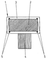
- the display instrument 1 is equipped with a TFT display 2, which two in This view arranged one behind the other glass plates 3 as substrates has and by means of a contact 4 with a not shown Control unit is connected.
- the as organic Diodes 5 designed sensors differ from those of the TFT displays also constructed from organic diodes, not shown 2 only by the type of control.
- the manufacturing process can be significantly simplified and the manufacturing costs be significantly reduced.
Abstract
Description
Die Erfindung betrifft ein mit einem ein erstes und ein zweites Substrat aufweisenden TFT-Display (Thin Film Transistor Display) ausgestattetes Anzeigeinstrument, insbesondere in einem Kraftfahrzeug, welches Anzeigeinstrument zur Bestimmung der Umgebungshelligkeit mit einem Sensor verbunden ist, wobei zwischen den Substraten eine Flüssigkristallsubstanz eingeschlossen ist und das erste Substrat an seiner der Flüssigkristallsubstanz zugewandten Seite Dünnfilmtransistoren und das zweite Substrat an seiner der Flüssigkristallsubstanz zugewandten Seite eine Gegenelektrode aufweist.The invention relates to a with a first and a second substrate TFT display (Thin Film Transistor Display) equipped Display instrument, especially in a motor vehicle, which Display instrument for determining the ambient brightness with a Sensor is connected, a liquid crystal substance between the substrates is enclosed and the first substrate at its the Liquid crystal substance facing side thin film transistors and that second substrate on its side facing the liquid crystal substance has a counter electrode.
Ein derart ausgestattetes Anzeigeinstrument wird in der Praxis im Kraft-fahrzeugbereich zunehmend eingesetzt und ist damit bekannt. Dabei dient das Anzeigeinstrument auch der Visualisierung sicherheitsrelevanter Informationen, die hierzu unter allen im Fahrbetrieb auftretenden Betriebsumständen fehlerfrei und zuverlässig ablesbar sein müssen. Insbesondere sind dabei die Extremlagen mit einerseits starker und direkter Sonneneinstrahlung auf das Anzeigeinstrument, andererseits Nachtfahrten mit geringem Restlichtanteil in der Umgebung zu berücksichtigen. A display instrument equipped in this way is used in practice in the motor vehicle sector increasingly used and is therefore known. It serves the display instrument also the visualization of safety-relevant Information on this under all operating circumstances occurring during driving must be error-free and reliably legible. In particular are the extreme locations with stronger and more direct on the one hand Sunlight on the display instrument, on the other hand night driving with little residual light in the environment.
Um unter den genannten Umständen einen sicheren Betrieb des Kraftfahrzeuges zu gewährleisten und eine unzureichende oder übermäßige Helligkeit des Displays zu vermeiden, die zu einer Ablenkung des Kraft-fahrzeugführers vom Verkehrsgeschehen führen kann, ist es daher erforderlich, das Anzeigeinstrument entsprechend der mittels des Sensors erfassten Umgebungshelligkeit anzusteuern. Hierzu wird der Sensor beispielsweise im Bereich einer das Anzeigeinstrument aufnehmenden Armaturentafel angeordnet.To ensure safe operation of the motor vehicle under the circumstances mentioned to ensure and insufficient or excessive Avoid brightness of the display, leading to a distraction of the driver it can lead from the traffic situation required, the display instrument corresponding to that by means of the sensor to control the detected ambient brightness. For this the sensor for example in the area of a receiving instrument Dashboard arranged.
Als nachteilig hat sich beim Stand der Technik erwiesen, dass es in der Praxis aus Platzgründen und aufgrund des optischen Erscheinungsbildes nicht möglich ist, dem Sensor eine zur Bestimmung der Helligkeit optimale Position zu verschaffen. Dabei wirkt sich hinderlich aus, dass bereits eine Position wenig abseits des Anzeigeinstrumentes zu einem fehlerhaften Messwert führen kann. Insbesondere schräg einfallendes Umgebungslicht kann dazu führen, dass der Sensor im Schatten liegt, während das Anzeigeinstrument als solches noch der vollen Lichteinstrahlung ausgesetzt ist.It has proven disadvantageous in the prior art that it is used in the Practice for reasons of space and due to the visual appearance it is not possible to give the sensor an optimal one for determining the brightness To provide position. The fact that one already has an adverse effect Position a little off the display instrument to a faulty one Measured value. In particular, ambient light entering at an angle can cause the sensor to be in shadow while the Display instrument as such still exposed to full light is.
Man könnte daran denken, die Helligkeit durch eine Vielzahl von im Innenraum des Kraftfahrzeuges verteilten Sensoren zu ermitteln, die in einer zentralen Steuereinheit ausgewertet werden, um daraus einen Durchschnittswert oder eine Wahrscheinlichkeit für die einfallende Umgebungshelligkeit zu bestimmen. Dies scheitert jedoch in der Praxis bereits an dem erheblichen Aufwand zur Kontaktierung der Sensoren. Weiterhin wird auch hierdurch eine fehlerhafte Bestimmung der Helligkeit nicht ausgeschlossen, sondern lediglich deren Wahrscheinlichkeit vermindert. Daher wird sich dieser Lösungsansatz aller Voraussicht nach bereits aus rein praktischen Überlegungen in der Serienfertigung nicht durchsetzen können. One could remember the brightness by a variety of im To determine the interior of the motor vehicle distributed sensors that in a central control unit can be evaluated to create a Average or a probability of the incident To determine ambient brightness. However, this fails in practice the considerable effort involved in contacting the sensors. This also results in an incorrect determination of the brightness not excluded, but only reduces their probability. Therefore, this approach will most likely already work not enforce in series production for purely practical reasons can.
Der Erfindung liegt das Problem zugrunde, ein Anzeigeinstrument der eingangs genannten Art so zu gestalten, dass eine möglichst genaue Erfassung der Umgebungshelligkeit mittels des Sensors ermöglicht wird.The invention is based on the problem of a display instrument to design in such a way that the most accurate possible Detection of the ambient brightness by means of the sensor is made possible.
Dieses Problem wird erfindungsgemäß dadurch gelöst, dass der Sensor in dem TFT-Display zwischen dem ersten und dem zweiten Substrat angeordnet ist. Hierdurch erfolgt die Bestimmung der Umgebungshelligkeit unmittelbar im Bereich des Displays, so dass mittels des Sensors ein realistischer Messwert der Helligkeit erfasst wird. Der so gewonnene Messwert ermöglicht beispielsweise die Ansteuerung einer Hintergrundbeleuchtung des Anzeigeinstrumentes mit einer für die Ablesbarkeit unter den vorherrschenden Umständen optimalen Helligkeit. Dabei sind lokale Helligkeitsdifferenzen zwischen der Position des Sensors und der Darstellungsfläche weitgehend ausgeschlossen. Zugleich wird der Herstellungsaufwand des Anzeigeinstrumentes wesentlich reduziert, da eine zusätzliche Verdrahtung, insbesondere zusätzlicher Sensoren im Innenraum des Kraftfahrzeuges, und die Verlegung von Leitungen im Kraftfahrzeug entfällt. Das erfindungsgemäße Anzeigeinstrument eignet sich dadurch auch für die Serienfertigung für Kraftfahrzeuge, aber auch für andere Einsatzgebiete, wie beispielsweise bei transportablen Rechnern oder bei Fernsehgeräten, die mit einem TFT-Display ausgestattet sind.According to the invention, this problem is solved in that the sensor in the TFT display between the first and the second substrate is arranged. This determines the ambient brightness directly in the area of the display, so that by means of the sensor realistic measured value of brightness is recorded. The so won For example, a measured value enables the control of a backlight of the display instrument with one for readability below the prevailing circumstances optimal brightness. There are local ones Differences in brightness between the position of the sensor and the display surface largely excluded. At the same time, the manufacturing effort of the display instrument significantly reduced, since one additional wiring, especially additional sensors in the interior of the motor vehicle, and the laying of lines in the motor vehicle not applicable. The display instrument according to the invention is suitable therefore also for series production for motor vehicles, but also for other areas of application, such as in portable computers or for televisions equipped with a TFT display.
Die Herstellung des Anzeigeinstruments wird gemäß einer vorteilhaften Weiterbildung der Erfindung besonders dann vereinfacht, wenn der Sensor an dem die Dünnfilmtransistoren aufweisenden ersten Substrat angeordnet ist. Auf diese Weise können Transistoren und Sensor in gleichen Verfahrensgängen hergestellt werden.The manufacture of the display instrument is advantageous Further development of the invention is particularly simplified if the Sensor on the first substrate having the thin film transistors is arranged. In this way, transistors and sensor in same procedures are produced.
Dabei ist eine besonders vorteilhafte Ausführungsform der Erfindung dadurch gegeben, dass der Sensor außerhalb eines Anzeigebereichs des Displays des Anzeigeinstrumentes angeordnet ist. Hierdurch ist der Sensor für einen Betrachter nicht oder zumindest nicht bei einem flüchtigen Blick erkennbar. Das optische Erscheinungsbild des Anzeigeinstrumentes wird demnach nicht durch den Sensor gestört. Weiterhin steht eine unveränderte Darstellungsfläche zu Verfügung, so dass die Ansteuerung zur Bilddarstellung in gewohnter Weise erfolgen kann.Here is a particularly advantageous embodiment of the invention given that the sensor is outside a display range of the Displays of the display instrument is arranged. This is the Sensor for a viewer not or at least not for a fleeting one Look recognizable. The visual appearance of the display instrument is therefore not disturbed by the sensor. Still stands an unchanged display area is available so that the control for image display can be done in the usual way.
Besonders empfehlenswert ist dabei auch eine Ausgestaltung der Erfindung, bei der der Sensor eine organische Diode aufweist. Solche organischen Dioden, zu denen insbesondere auch Polymer-Substanzen zählen, ermöglichen einerseits die Bestimmung der Helligkeit des einfallenden Lichtes aufgrund der damit einhergehenden Spannungsänderung, andererseits ermöglichen sie umgekehrt auch die Verwendung zur Bilddarstellung durch Anlegen einer Spannung. Die als Sensor verwendete organische Diode unterscheidet sich daher von einem mit entsprechenden Dioden ausgestatteten TFT-Display im wesentlichen nur durch die Art der Ansteuerung, so dass eine äußerst kompakte und platzsparende Einheit aus TFT-Display und Sensor erreicht wird. Hierzu kann beispielsweise jeweils ein äußerer Eckpunkt der Display-Fläche entsprechend angesteuert und als Sensor verwendet werden. Weiterhin kann dabei zugleich der Herstellungsaufwand weiter reduziert werden.An embodiment of the invention is also particularly recommended, in which the sensor has an organic diode. Such organic Diodes, which include polymer substances in particular, allow on the one hand the determination of the brightness of the incident Light due to the associated change in voltage, on the other hand, they also allow the use for Image display by applying a voltage. The one used as a sensor organic diode therefore differs from one with corresponding ones TFT display equipped essentially only by diodes the type of control, making it extremely compact and space-saving Unit of TFT display and sensor is reached. This can for example, an outer corner point of the display area accordingly controlled and used as a sensor. Furthermore can at the same time the manufacturing effort can be further reduced.
Hierbei ist eine besonders vorteilhafte Weiterbildung der Erfindung dadurch gegeben, dass das Display mit Dioden ausgestattet ist, die wahlweise entweder zur Bilddarstellung oder als Sensor zur Bestimmung der Umgebungshelligkeit einsetzbar sind. Hierdurch werden jeweils solche organische Dioden zur Bestimmung der Helligkeit verwendet, die jeweils zur Bilddarstellung des TFT-Displays nicht benötigt und daher nicht angesteuert werden. Die Auswahl des Sensors aus dem Feld der Dioden erfolgt daher nach der jeweils darzustellenden Abbildung, so dass keine Einschränkung der Darstellungsfläche aufgrund des Sensors erfolgt. Zugleich kann dabei die Auswahl der jeweils zur Bestimmung der Helligkeit als Sensor heranzuziehenden Diode bevorzugt aus dem Zentrum der Display-Fläche erfolgen, wodurch die Messgenauigkeit in bezug auf eine möglichst realistische Erfassung der Umgebungshelligkeit weiter erhöht werden kann.Here is a particularly advantageous development of the invention given that the display is equipped with diodes that either for image display or as a sensor for determination the ambient brightness can be used. As a result, such organic diodes used to determine brightness, each not required for image display of the TFT display and therefore not can be controlled. The selection of the sensor from the field of diodes is therefore based on the illustration to be displayed, so that none The display area is restricted due to the sensor. At the same time, the selection can be used to determine the brightness diode to be used as a sensor preferably from the center of the Display area take place, whereby the measuring accuracy in relation to a detection of the ambient brightness, which is as realistic as possible, is further increased can be.
Die Erfindung lässt verschiedene Ausführungsformen zu. Zur weiteren
Verdeutlichung ihres Grundprinzips ist eine davon in der Zeichnung
dargestellt und wird nachfolgend beschrieben. Diese zeigt in einer
Prinzipskizze eine Draufsicht auf ein Anzeigeinstrument 1. Das Anzeigeinstrument
1 ist mit einem TFT-Display 2 ausgestattet, welches zwei in
dieser Ansicht hintereinander angeordnete Glasplatten 3 als Substrate
aufweist und mittels einer Kontaktierung 4 mit einer nicht dargestellten
Steuereinheit verbunden ist. An einer dieser Glasplatten 3 sind vier jeweils
an einer Ecke des TFT-Displays 2 außerhalb des Display-Anzeigebereichs
positionierte Sensoren 5 zur Bestimmung der Helligkeit
des einfallenden Umgebungslichtes angeordnet. Die als organische
Dioden ausgeführten Sensoren 5 unterscheiden sich von denjenigen des
ebenfalls aus nicht dargestellten organischen Dioden aufgebauten TFT-Displays
2 lediglich durch die Art der Ansteuerung. Der Herstellungsprozess
kann dadurch wesentlich vereinfacht und die Fertigungskosten
erheblich reduziert werden.The invention permits various embodiments. For further
Clarification of their basic principle is one of them in the drawing
shown and will be described below. This shows in one
Schematic diagram of a top view of a
Claims (5)
Applications Claiming Priority (2)
| Application Number | Priority Date | Filing Date | Title |
|---|---|---|---|
| DE19955499 | 1999-11-18 | ||
| DE19955499A DE19955499A1 (en) | 1999-11-18 | 1999-11-18 | Display instrument |
Publications (2)
| Publication Number | Publication Date |
|---|---|
| EP1102109A1 true EP1102109A1 (en) | 2001-05-23 |
| EP1102109B1 EP1102109B1 (en) | 2002-10-02 |
Family
ID=7929483
Family Applications (1)
| Application Number | Title | Priority Date | Filing Date |
|---|---|---|---|
| EP00123112A Expired - Lifetime EP1102109B1 (en) | 1999-11-18 | 2000-10-25 | Display apparatus |
Country Status (3)
| Country | Link |
|---|---|
| EP (1) | EP1102109B1 (en) |
| DE (2) | DE19955499A1 (en) |
| ES (1) | ES2184674T3 (en) |
Families Citing this family (3)
| Publication number | Priority date | Publication date | Assignee | Title |
|---|---|---|---|---|
| JP4166512B2 (en) * | 2001-09-04 | 2008-10-15 | 株式会社デンソー | Vehicle instrument |
| DE102004063594A1 (en) | 2004-12-30 | 2006-07-13 | BSH Bosch und Siemens Hausgeräte GmbH | Method for controlling the backlight of a display |
| DE102005008175A1 (en) * | 2005-02-23 | 2006-08-31 | Robert Bosch Gmbh | Operational device e.g. ballast, for high voltage discharge lamp utilized as search light of motor vehicle, has shielding provided in electrical lead in region of opening of shielding housing, and electrically, directly contacting housing |
Citations (6)
| Publication number | Priority date | Publication date | Assignee | Title |
|---|---|---|---|---|
| EP0224869A1 (en) * | 1985-11-27 | 1987-06-10 | Hosiden Corporation | Transmitting type display device |
| EP0605246A2 (en) * | 1992-12-28 | 1994-07-06 | Canon Kabushiki Kaisha | Sight line detector, display unit, view finder and unit and camera with the same display unit |
| US5504323A (en) * | 1993-12-07 | 1996-04-02 | The Regents Of The University Of California | Dual function conducting polymer diodes |
| DE19737942A1 (en) * | 1997-08-30 | 1999-03-11 | Mannesmann Vdo Ag | Display device for mounting in motor vehicle |
| DE19848547A1 (en) * | 1997-11-07 | 1999-05-12 | Mannesmann Vdo Ag | Display device |
| US5952992A (en) * | 1995-07-17 | 1999-09-14 | Dell U.S.A., L.P. | Intelligent LCD brightness control system |
Family Cites Families (1)
| Publication number | Priority date | Publication date | Assignee | Title |
|---|---|---|---|---|
| US5818553A (en) * | 1995-04-10 | 1998-10-06 | Norand Corporation | Contrast control for a backlit LCD |
-
1999
- 1999-11-18 DE DE19955499A patent/DE19955499A1/en not_active Withdrawn
-
2000
- 2000-10-25 ES ES00123112T patent/ES2184674T3/en not_active Expired - Lifetime
- 2000-10-25 EP EP00123112A patent/EP1102109B1/en not_active Expired - Lifetime
- 2000-10-25 DE DE50000595T patent/DE50000595D1/en not_active Expired - Lifetime
Patent Citations (6)
| Publication number | Priority date | Publication date | Assignee | Title |
|---|---|---|---|---|
| EP0224869A1 (en) * | 1985-11-27 | 1987-06-10 | Hosiden Corporation | Transmitting type display device |
| EP0605246A2 (en) * | 1992-12-28 | 1994-07-06 | Canon Kabushiki Kaisha | Sight line detector, display unit, view finder and unit and camera with the same display unit |
| US5504323A (en) * | 1993-12-07 | 1996-04-02 | The Regents Of The University Of California | Dual function conducting polymer diodes |
| US5952992A (en) * | 1995-07-17 | 1999-09-14 | Dell U.S.A., L.P. | Intelligent LCD brightness control system |
| DE19737942A1 (en) * | 1997-08-30 | 1999-03-11 | Mannesmann Vdo Ag | Display device for mounting in motor vehicle |
| DE19848547A1 (en) * | 1997-11-07 | 1999-05-12 | Mannesmann Vdo Ag | Display device |
Also Published As
| Publication number | Publication date |
|---|---|
| EP1102109B1 (en) | 2002-10-02 |
| DE50000595D1 (en) | 2002-11-07 |
| ES2184674T3 (en) | 2003-04-16 |
| DE19955499A1 (en) | 2001-05-23 |
Similar Documents
| Publication | Publication Date | Title |
|---|---|---|
| EP1062652B1 (en) | Liquid crystal display with active matrix | |
| DE102005052007B4 (en) | Display unit for a vehicle | |
| DE102014207420B4 (en) | Liquid crystal display and method of testing a liquid crystal display | |
| DE102007023030B4 (en) | Liquid crystal display device with an image sensor and method for its control | |
| EP2463152B1 (en) | Lighting element in external mirror | |
| DE102018215185B3 (en) | Method, apparatus and computer-readable storage medium with instructions for setting a head-up display in a motor vehicle, adjusting device for use in such a method or with such a device | |
| DE3714072C2 (en) | ||
| EP0433289A1 (en) | Display device for motor vehicles | |
| DE102008012307A1 (en) | display device | |
| DE102016124683A1 (en) | Thin-film transistor substrate and display device provided therewith | |
| EP1899191B1 (en) | Combination instrument for a motor vehicle | |
| DE19737942C2 (en) | Display unit provided for fastening in a motor vehicle | |
| DE4228962C2 (en) | Optical system for enlarging a display field | |
| EP1112529A1 (en) | Liquid crystal display system and method of operating a liquid crystal display device with visual failure control | |
| EP1102109B1 (en) | Display apparatus | |
| DE19757545A1 (en) | Display device for automobile dashboard | |
| DE2507376A1 (en) | DISPLAY DEVICE | |
| DE112015006579T5 (en) | Display confirmation device, liquid crystal display device, meter display, and display confirmation method | |
| DE10062723A1 (en) | Head-Up Display | |
| DE19737726C1 (en) | Display instrument for automobile dashboard | |
| CH690342A5 (en) | Method and apparatus for securing that appears in an image data. | |
| EP1510995A2 (en) | Display apparatus | |
| DE10244792B4 (en) | display device | |
| DE3314632A1 (en) | ARRANGEMENT FOR REDUCING THE REMAINING TRANSMISSION OF LCD DISPLAYS | |
| DE102006017931B4 (en) | Display device for motor vehicle test stands |
Legal Events
| Date | Code | Title | Description |
|---|---|---|---|
| PUAI | Public reference made under article 153(3) epc to a published international application that has entered the european phase |
Free format text: ORIGINAL CODE: 0009012 |
|
| AK | Designated contracting states |
Kind code of ref document: A1 Designated state(s): AT BE CH CY DE DK ES FI FR GB GR IE IT LI LU MC NL PT SE |
|
| AX | Request for extension of the european patent |
Free format text: AL;LT;LV;MK;RO;SI |
|
| RAP1 | Party data changed (applicant data changed or rights of an application transferred) |
Owner name: SIEMENS AKTIENGESELLSCHAFT |
|
| 17P | Request for examination filed |
Effective date: 20011119 |
|
| AKX | Designation fees paid |
Free format text: DE ES FR GB |
|
| GRAG | Despatch of communication of intention to grant |
Free format text: ORIGINAL CODE: EPIDOS AGRA |
|
| GRAG | Despatch of communication of intention to grant |
Free format text: ORIGINAL CODE: EPIDOS AGRA |
|
| GRAH | Despatch of communication of intention to grant a patent |
Free format text: ORIGINAL CODE: EPIDOS IGRA |
|
| 17Q | First examination report despatched |
Effective date: 20020410 |
|
| GRAH | Despatch of communication of intention to grant a patent |
Free format text: ORIGINAL CODE: EPIDOS IGRA |
|
| GRAA | (expected) grant |
Free format text: ORIGINAL CODE: 0009210 |
|
| AK | Designated contracting states |
Kind code of ref document: B1 Designated state(s): DE ES FR GB |
|
| REG | Reference to a national code |
Ref country code: GB Ref legal event code: FG4D Free format text: NOT ENGLISH |
|
| REF | Corresponds to: |
Ref document number: 50000595 Country of ref document: DE Date of ref document: 20021107 |
|
| GBT | Gb: translation of ep patent filed (gb section 77(6)(a)/1977) |
Effective date: 20021220 |
|
| REG | Reference to a national code |
Ref country code: ES Ref legal event code: FG2A Ref document number: 2184674 Country of ref document: ES Kind code of ref document: T3 |
|
| ET | Fr: translation filed | ||
| PLBE | No opposition filed within time limit |
Free format text: ORIGINAL CODE: 0009261 |
|
| STAA | Information on the status of an ep patent application or granted ep patent |
Free format text: STATUS: NO OPPOSITION FILED WITHIN TIME LIMIT |
|
| 26N | No opposition filed |
Effective date: 20030703 |
|
| PGFP | Annual fee paid to national office [announced via postgrant information from national office to epo] |
Ref country code: GB Payment date: 20041012 Year of fee payment: 5 |
|
| PG25 | Lapsed in a contracting state [announced via postgrant information from national office to epo] |
Ref country code: GB Free format text: LAPSE BECAUSE OF NON-PAYMENT OF DUE FEES Effective date: 20051025 |
|
| GBPC | Gb: european patent ceased through non-payment of renewal fee |
Effective date: 20051025 |
|
| REG | Reference to a national code |
Ref country code: ES Ref legal event code: PC2A Owner name: CONTINENTAL AUTOMOTIVE GMBH Effective date: 20110325 |
|
| REG | Reference to a national code |
Ref country code: FR Ref legal event code: TP |
|
| PGFP | Annual fee paid to national office [announced via postgrant information from national office to epo] |
Ref country code: ES Payment date: 20141028 Year of fee payment: 15 |
|
| REG | Reference to a national code |
Ref country code: DE Ref legal event code: R084 Ref document number: 50000595 Country of ref document: DE |
|
| REG | Reference to a national code |
Ref country code: FR Ref legal event code: PLFP Year of fee payment: 16 |
|
| REG | Reference to a national code |
Ref country code: FR Ref legal event code: PLFP Year of fee payment: 17 |
|
| REG | Reference to a national code |
Ref country code: ES Ref legal event code: FD2A Effective date: 20161129 |
|
| PG25 | Lapsed in a contracting state [announced via postgrant information from national office to epo] |
Ref country code: ES Free format text: LAPSE BECAUSE OF NON-PAYMENT OF DUE FEES Effective date: 20151026 |
|
| REG | Reference to a national code |
Ref country code: FR Ref legal event code: PLFP Year of fee payment: 18 |
|
| PGFP | Annual fee paid to national office [announced via postgrant information from national office to epo] |
Ref country code: DE Payment date: 20171031 Year of fee payment: 18 Ref country code: FR Payment date: 20171024 Year of fee payment: 18 |
|
| REG | Reference to a national code |
Ref country code: DE Ref legal event code: R119 Ref document number: 50000595 Country of ref document: DE |
|
| PG25 | Lapsed in a contracting state [announced via postgrant information from national office to epo] |
Ref country code: DE Free format text: LAPSE BECAUSE OF NON-PAYMENT OF DUE FEES Effective date: 20190501 |
|
| PG25 | Lapsed in a contracting state [announced via postgrant information from national office to epo] |
Ref country code: FR Free format text: LAPSE BECAUSE OF NON-PAYMENT OF DUE FEES Effective date: 20181031 |