Stand der TechnikState of the art
Die Erfindung geht aus von einer Anzeigevorrichtung nach der Gattung des Hauptanspruchs. Eine solche Anzeigevorrichtung ist aus der US 2001/0008395 A1 bekannt. Der Kontrast flächiger Anzeigen, insbesondere von Flüssigkristallanzeigen, ist einerseits von der Höhe der angelegten Ansteuerspannung, aber auch von der Einsatztemperatur der Anzeige abhängig. Es ist bekannt, in der Fertigung der Anzeige den Kontrast entsprechend einzustellen bzw. eine manuelle Nachregelung über ein entsprechendes Bedienelement zuzulassen. Um die Temperaturabhängigkeit auszugleichen, ist es ferner bekannt, einen Temperatursensor vorzusehen, so dass die Ansteuerspannung und damit der Anzeigenkontrast in Abhängigkeit von der gemessenen Temperatur nachgeregelt werden kann. Im Allgemeinen ist es dabei nicht möglich, den Temperatursensor unmittelbar mit der Anzeigeeinheit zu verbinden, so dass es z. B. durch Sonneneinstrahlung zu Temperaturdifferenzen zwischen der Anzeigeneinheit und der mit dem Sensor gemessenen Umgebungstemperatur kommen kann. Hierdurch kann gegebenenfalls die Ansteuerspannung nicht entsprechend der tatsächlichen Anzeigenhelligkeit nachgeregelt werden. Ferner ist es aus der DE 41 29 846 bekannt, einen optischen Sensor an der Anzeigefläche vorzusehen. Für den Betrieb dieses Sensors ist jedoch Umgebungslicht erforderlich, so dass z. B. bei Dunkelheit der Umgebung eine entsprechende Anpassung nicht erfolgen kann.The invention relates to a display device according to the preamble of the main claim. Such a display device is from the US 2001/0008395 A1 known. The contrast of flat displays, in particular of liquid crystal displays, on the one hand depends on the level of the applied drive voltage, but also on the operating temperature of the display. It is known in the manufacture of the display to set the contrast accordingly or to allow a manual readjustment via a corresponding control element. To compensate for the temperature dependence, it is also known to provide a temperature sensor, so that the drive voltage and thus the display contrast can be readjusted depending on the measured temperature. In general, it is not possible to connect the temperature sensor directly to the display unit, so that it z. B. by sunlight to temperature differences between the display unit and the ambient temperature measured with the sensor can come. As a result, if appropriate, the drive voltage can not be readjusted according to the actual display brightness. Furthermore, it is from the DE 41 29 846 known to provide an optical sensor on the display surface. For the operation of this sensor, however, ambient light is required, so that z. B. in the dark the environment can not be made a corresponding adjustment.
Aus der US 2001/0008395 A1 ist eine transmissive Flüssigkristallanzeige der eingangs genannten Art bekannt, bei der ein optischer Sensor an einer Vorderseite angeordnet ist. Die Anzeige wird über eine Rückbeleuchtung beleuchtet. Der optische Sensor misst das von der Flüssigkristallanzeige abgegebene Licht, um die Helligkeit zu korrigieren. Die Rückbeleuchtung besteht insbesondere aus einer Lampe, einem Reflektor, einem Lichtleiter und einem Diffusor. Ausgehend von der Lampe wird das Licht über den Reflektor, über den Lichtleiter und den Diffusor zu der Flüssigkristallanzeige geleitet.From the US 2001/0008395 A1 a transmissive liquid crystal display of the aforementioned type is known in which an optical sensor is arranged on a front side. The display is illuminated via a backlight. The optical sensor measures the light emitted by the liquid crystal display to correct the brightness. The backlight consists in particular of a lamp, a reflector, a light guide and a diffuser. Starting from the lamp, the light is directed via the reflector, over the light guide and the diffuser to the liquid crystal display.
Vorteile der ErfindungAdvantages of the invention
Die erfindungsgemäße Anzeigevorrichtung mit den Merkmalen des Hauptanspruchs hat demgegenüber den Vorteil, dass Licht zum Durchleuchten der Anzeigeeinheit mit einem Lichtleiter zu der Anzeigeeinheit geführt wird, diese durchleuchtet und anschließend die Lichtdurchlässigkeit mit einem hierfür geeigneten Mittel messbar ist. Mit der Lichtzuführung über einen Lichtleiter ist eine von der Umgebungshelligkeit der Anzeigeeinheit unabhängige Kontrastmessung der Anzeige möglich. Zudem wird auch montagetechnisch einfach eine Durchleuchtung des Anzeigemittels ermöglicht, da lediglich auf einer Seite des Anzeigemittels ein elektrisches Bauteil angeordnet werden muss. Besonders vorteilhaft ist dabei, das Licht aus dem Lichtleiter auf einer einer in der Anzeigevorrichtung vorgesehenen Lichtquelle abgewandten Seite in das Anzeigemittel einzustrahlen. Hierdurch wird es ermöglicht, auf der einem Betrachter zugewandten Seite des Anzeigemittels, also auf einer Außenseite der Anzeigevorrichtung, lediglich den platzsparend anbringbaren Lichtleiter vorzusehen, ohne dass elektrische Teile zur Lichtdetektion an eine Außenseite der Vorrichtung montiert werden müssen.The display device according to the invention with the features of the main claim has the advantage that light is passed to the illumination of the display unit with a light guide to the display unit, this screened and then the light transmission with a suitable means is measurable. With the light supply via a light guide independent of the ambient brightness of the display unit contrast measurement of the display is possible. In addition, a screening of the display means is also possible in terms of assembly technology, since an electrical component only has to be arranged on one side of the display means. It is particularly advantageous to irradiate the light from the light guide on a side facing away from a light source provided in the light source side in the display means. This makes it possible to provide on the side facing the viewer of the display means, ie on an outer side of the display device, only the space-saving attachable light guide without electrical parts for light detection must be mounted on an outside of the device.
Es ist ferner vorteilhaft, eine künstliche Lichtquelle zur Durchleuchtung des Anzeigemittels für den Testvorgang des Anzeigemittels derart vorzusehen, dass eine Variation der Helligkeit dieser Lichtquelle das übrige Erscheinungsbild, insbesondere die Darstellung einer in dem Anzeigemittel auszugebenden Information, nicht beeinflusst. Hierdurch kann auch während des Betriebs der Anzeigevorrichtung eine Überprüfung des Anzeigemittels erfolgen.It is also advantageous to provide an artificial light source for scanning the display means for the test procedure of the display means such that a variation of the brightness of this light source does not affect the remaining appearance, in particular the representation of an information to be output in the display means. As a result, the display device can also be checked during operation of the display device.
Es ist ferner vorteilhaft, die Ansteuerung des Anzeigemittels in Abhängigkeit von der gemessenen Lichtdurchlässigkeit derart zu regeln, dass stets ein vorgegebener Kontrast zwischen einer maximalen Helligkeit und einem maximalen Dunkelwert der Anzeige und somit eine gewünschte Ablesbarkeit der Anzeige für einen Betrachter gewährleitstet ist.It is also advantageous to regulate the control of the display means in dependence on the measured light transmittance such that always a predetermined contrast between a maximum brightness and a maximum dark value of the display and thus a desired readability of the display for a viewer is gewährleitstet.
Es ist ferner vorteilhaft, einen Bereich des Anzeigemittels zwischen einem Lichtauskoppelbereich des Lichtleiters und dem Mittel zur Messung der Lichtdurchlässigkeit unabhängig von dem übrigen Anzeigemittel ansteuerbar vorzusehen, so dass auch bei einer Variation dieses Bereichs des Anzeigemittels das übrige Anzeigebild unverändert bleibt.It is also advantageous to provide a region of the display means between a Lichtauskoppelbereich of the light guide and the means for measuring the light transmission independently controllable independently of the remaining display means, so that even with a variation of this range of the display means, the remaining display image remains unchanged.
Besonders vorteilhaft ist ferner, bei einer festgestellten Fehlfunktion eine insbesondere akustische Warnung auszugeben, so dass ein Benutzer über die Fehlfunktion, insbesondere über eine schlechte Ablesbarkeit der Anzeigevorrichtung, informiert wird. Dies ist insbesondere bei sicherheitskritischen Anwendungen von Vorteil, bei denen ein Benutzer über möglicherweise auftretende kritische Zustande des der Anzeigevorrichtung zugeordneten Systems unmittelbar informiert werden muss und sich der Benutzer demzufolge auf die ihm von der Anzeigevorrichtung vermittelten Informationen verlassen muss.It is also particularly advantageous to issue a particular acoustic warning in case of a detected malfunction, so that a user is informed about the malfunction, in particular about a poor readability of the display device. This is particularly advantageous in safety-critical applications in which a user must be informed immediately about possibly occurring critical states of the system associated with the display device and the user must therefore rely on the information conveyed to him by the display device.
Ferner ist vorteilhaft, ein erstes und ein zweites Mittel zur Messung der Lichtdurchlässigkeit vorzusehen, wobei das Anzeigemittel derart angesteuert wird, dass mit dem ersten Mittel zur Messung der Lichtdurchlässigkeit eine maximale Transparenz der Anzeigeeinheit und mit dem zweiten Mittel zur Messung der Lichtdurchlässigkeit eine maximale Absorption des Anzeigemittels gemessen wird. Aus einem Differenzsignal kann dann unmittelbar der maximal erreichbare Kontrast des Anzeigemittels ermittelt und gegebenenfalls eine hierfür vorgesehene Steuerung der Anzeige entsprechend angepasst werden.Further, it is advantageous to provide a first and a second means for measuring the light transmittance, wherein the display means is driven such that with the first means for measuring the light transmittance, a maximum transparency of the display unit and the second means for Measuring the light transmission a maximum absorption of the indicating means is measured. From a difference signal can then be determined directly the maximum achievable contrast of the display means and optionally a designated control of the display can be adjusted accordingly.
Insbesondere ist vorteilhaft, bei der Verwendung einer Flüssigkristallanzeige als Anzeigemittel eine erfindungsgemäße Ausgestaltung vorzusehen, da Flüssigkristallzellen eine recht starke Temperaturabhängigkeit ihres Kontrastes aufweisen.In particular, it is advantageous to provide an inventive design when using a liquid crystal display as a display means, since liquid crystal cells have a fairly strong temperature dependence of their contrast.
Zeichnungdrawing
Ausführungsbeispiele der Erfindung sind in der Zeichnung dargestellt und in der nachfolgenden Beschreibung näher erläutert. Es zeigenEmbodiments of the invention are illustrated in the drawings and explained in more detail in the following description. Show it
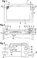
1 eine Aufsicht auf einer erfindungsgemäße Anzeigevorrichtung, 1 a plan view of a display device according to the invention,
2 eine Seitenansicht einer erfindungsgemäßen Anzeigevorrichtung. 2 a side view of a display device according to the invention.
3 einen schematische Aufbau einer erfindungsgemäßen Anzeigevorrichtung. 3 a schematic structure of a display device according to the invention.
Beschreibung des AusführungsbeispielsDescription of the embodiment
Die erfindungsgemäße Anzeigevorrichtung kann für beliebige Anzeigezwecke verwendet werden. Insbesondere ist die Verwendung vorteilhaft für Anwendungen, bei denen die Anzeigevorrichtung starken Temperaturschwankungen unterliegt. die gegebenenfalls den Anzeigenkontrast beeinflussen können. Insbesondere bei der Verwendung in Kraftfahrzeugen können derartig starke Temperaturunterschiede z. B. in Folge von Sonneneinstrahlung oder nach einem Parken des Fahrzeugs in unbeheiztem Zustand im Winter auftreten.The display device according to the invention can be used for any display purposes. In particular, the use is advantageous for applications in which the display device is subject to strong temperature fluctuations. which may influence the display contrast. In particular, when used in motor vehicles such strong temperature differences z. B. occur as a result of sunlight or after parking the vehicle in the unheated state in winter.
In der 1 ist eine Anzeigevorrichtung 1 in Aufsicht mit einem Anzeigemittel gezeigt, das als ein lichtdurchlässiges Anzeigemittel ausgeführt ist, dessen Transparenz durch das Anlegen einer entsprechenden Spannung veränderlich ist. Insbesondere werden als Anzeigemittel hierzu Flüssigkristallzellen oder Elektrolumineszenzanzeigen verwendet. In einer bevorzugten Ausgestaltung ist das Anzeigemittel als eine Flüssigkristallzelle 2 ausgeführt, die in einem Gehäuserahmen 3 gehalten ist. Die Flüssigkristallzelle 2 weist einzelne Bildpunkte 4 auf, die einzeln ansteuerbar sind und durch deren Zusammensetzung sich ein in der Flüssigkristallanzeige darzustellendes Bild ergibt. Das Bild kann als ein Standbild z. B. eine Menüauswahl zur Funktionseingabe oder eine Straßenkartendarstellung darstellen. Die Anzeige kann bei einem bewegten Betrieb auch z. B. Filmaufnahmen oder ein Fernsehbild zeigen. In einer bevorzugten Ausführungsform ist die Flüssigkristallzelle 2 als eine farbige Flüssigkristallzelle ausgeführt, die einzelne rote, grüne und blaue Bildpunkte aufweist, um einen farbigen Bildeindruck zu erreichen. Ein Teilbereich der Flüssigkristallzelle, ein Randbereich 5, ist an einer kurzen Seite der Flüssigkristallzelle von einem Steg des Gehäuserahmens 3 bedeckt, so dass der Randbereich für einen Betrachter der Flüssigkristallzelle 2 infolge der Abdeckung nicht sichtbar ist. Der unter dem Gehäuserahmen 3 liegende Randbereich 5 der Flüssigkristallzelle 2 ist in der 1 gestrichelt hervorgehoben. Zum Testen der Funktion und insbesondere zur Überprüfung des maximal erreichbaren Kontrastes des Anzeigemittels sind Mittel zur Messung der Lichtdurchlässigkeit an dem Anzeigemittel angeordnet. In dem Randbereich 5 sind eine erste Photodiode 6 und eine zweite Photodiode 7 auf einer Rückseite der Flüssigkristallzelle 2 angeordnet, also auf einer einem Betrachter der Anzeigevorrichtung 1 abgewandten Seite im Inneren des durch den Gehäuserahmen 3 abgeschlossenen Gehäuses der Anzeigevorrichtung 1.In the 1 is a display device 1 shown in plan view with a display means, which is designed as a translucent display means whose transparency is variable by the application of a corresponding voltage. In particular, liquid crystal cells or electroluminescent displays are used as display means for this purpose. In a preferred embodiment, the display means is a liquid crystal cell 2 Running in a rack 3 is held. The liquid crystal cell 2 has individual pixels 4 which are individually controllable and whose composition results in an image to be displayed in the liquid crystal display. The picture can be used as a still picture z. B. represent a menu selection for function input or a road map display. The display can also be z. B. filming or a television picture show. In a preferred embodiment, the liquid crystal cell is 2 designed as a colored liquid crystal cell having individual red, green and blue pixels to achieve a colored image impression. A subarea of the liquid crystal cell, a border area 5 , is on a short side of the liquid crystal cell of a web of the housing frame 3 covered so that the edge area for a viewer of the liquid crystal cell 2 as a result of the cover is not visible. The under the case frame 3 lying edge area 5 the liquid crystal cell 2 is in the 1 dashed highlighted. For testing the function and in particular for checking the maximum achievable contrast of the display means, means for measuring the light transmission are arranged on the display means. In the border area 5 are a first photodiode 6 and a second photodiode 7 on a back side of the liquid crystal cell 2 arranged, so on a viewer of the display device 1 away from the inside of the housing frame 3 enclosed housing of the display device 1 ,
In der 2 ist eine Seitenansicht der Anzeigevorrichtung 1 entlang der Schnittlinie II dargestellt. In der Flüssigkristallzelle 2 sind schematisch einzelne Bildpunkte 4 dargestellt. Die Flüssigkristallzelle 2 ist durch vorzugsweise elastisch ausgeführte Abstandshalter 17 von dem Gehäuserahmen 3 getrennt, wobei die Flussigkristallzelle 2 auf den Abstandshaltern 17 aufliegt. Die Flüssigkristallzelle 2 wird über an einer Leiterplatte 8 angeordnete Lichtquellen 9 hinterleuchtet.In the 2 is a side view of the display device 1 shown along the section line II. In the liquid crystal cell 2 are schematically individual pixels 4 shown. The liquid crystal cell 2 is preferably by elastically running spacers 17 from the case frame 3 separated, wherein the Flussigkristallzelle 2 on the spacers 17 rests. The liquid crystal cell 2 is over on a circuit board 8th arranged light sources 9 backlit.
Ebenfalls an der Leiterplatte 8 sind weitere elektrische Bauteile 10 angeordnet. Insbesondere ist auch eine in der 2 nicht dargestellte Treibereinheit zur Zeilen- und Spaltenansteuerung der Flüssigkristallzelle vorgesehen. Die Ansteuerungsinformationen werden von der Treibereinheit über einen flexiblen Leiter 11 an die Flüssigkristallzelle 2 zum Ansteuern der einzelnen Bildpunkte 4 übertragen. In dem Randbereich 5 verfügt die Flüssigkristallzelle 2 über mindestens einen weiteren Bildpunkt oder Bildpunktbereich 12, der zwischen der ersten Photodiode 6 und einem Lichtleiter 20 angeordnet ist, der von einer Lichtquelle 19, die auf der Leiterplatte 8 angeordnet ist, vorzugsweise gebogen zu dem Randbereich 5 an der Flüssigkristallzelle 2 führt. Der Lichtleiter 20 ist dabei derart ausgeführt, dass er sein Licht in die Flüssigkristallzelle 2 in den Randbereich 5 einkoppelt, wobei das Licht die Flüssigkristallzelle 2 durchstrahlt und zu der ersten Photodiode 6 gelangt. Zur Lichtauskopplung weist der Lichtleiter 20 in einer ersten Ausführungsform an seiner dem Randbereich 5 der Flüssigkristallzelle 2 zuweisenden Kontaktfläche eine aufgeraute oder bedruckte Oberfläche auf, durch die das in dem Lichtleiter geführte Licht in Richtung des Anzeigemittels aus dem Lichtleiter ausgekoppelt wird. In einem weiteren Ausführungsbeispiel kann der Lichtleiter 20 auch in optischem Kontakt zu einer Glas- oder Kunststofffläche der Flüssigkristallzelle 2 stehen, so dass das Licht unmittelbar in die Flüssigkristallzelle 2 eingekoppelt wird. Vorzugsweise wird dabei das Licht möglichst senkrecht durch die Flüssigkristallzelle hindurch gestrahlt, um blickwinkelabhängige Effekte bei der Messung auszuschließen und insbesondere eine Kontrastmessung für eine senkrechte Betrachtungsrichtung gegenüber der Flüssigkristallanzeige zu ermöglichen. Hierdurch wird z. B. ein störender Einfluss einer bei sehr geringen Betrachtungswinkeln auftretenden Helligkeitsinversion der Anzeigedarstellung vermieden. In einer weiteren Ausführungsform kann auf die Kontaktfläche des Lichtleiters 20 hierzu auch eine geeignete Mikroprismenstruktur aufgebracht werden. Die Lichtquellen 9 und die Lichtquelle 19 sind in einer ersten Ausführungsform als Leuchtdioden ausgeführt. Es können jedoch auch beliebige andere Lichtquellen, z. B. Kaltkathodenfluoreszenzlampen, verwendet werden.Also on the circuit board 8th are other electrical components 10 arranged. In particular, one in the 2 not shown driver unit for row and column drive of the liquid crystal cell provided. The drive information is provided by the driver unit via a flexible conductor 11 to the liquid crystal cell 2 for driving the individual pixels 4 transfer. In the border area 5 has the liquid crystal cell 2 over at least one further pixel or pixel area 12 that is between the first photodiode 6 and a light guide 20 is arranged by a light source 19 on the circuit board 8th is arranged, preferably bent to the edge region 5 at the liquid crystal cell 2 leads. The light guide 20 is designed such that it sheds light into the liquid crystal cell 2 in the border area 5 coupled, wherein the light is the liquid crystal cell 2 radiates through and to the first photodiode 6 arrives. For light extraction, the light guide 20 in a first embodiment at its edge area 5 the liquid crystal cell 2 assigning contact surface on a roughened or printed surface through which the guided in the light guide light is coupled out in the direction of the display means of the light guide. In a further embodiment can the light guide 20 also in optical contact with a glass or plastic surface of the liquid crystal cell 2 stand, allowing the light directly into the liquid crystal cell 2 is coupled. Preferably, the light is irradiated as vertically as possible through the liquid crystal cell in order to exclude viewing angle-dependent effects in the measurement and in particular to allow a contrast measurement for a vertical viewing direction relative to the liquid crystal display. As a result, z. B. a disturbing influence of occurring at very low viewing angles brightness inversion of the display display avoided. In a further embodiment, the contact surface of the light guide can be used 20 For this purpose, a suitable microprism structure can be applied. The light sources 9 and the light source 19 are designed as light-emitting diodes in a first embodiment. However, it can also be any other light sources, eg. As cold cathode fluorescent lamps can be used.
Die erste Photodiode 6 ist über eine elektrische Verbindung 13 mit der Leiterplatte 8 verbunden, wobei auf der Leiterplatte 8 ebenfalls eine nicht gezeigte Auswerteeinheit zur Messung der empfangenen Helligkeit angeordnet ist. Über diese Einheit wird vorzugsweise die Lichtquelle 19 angesteuert, die zur Einkopplung von Licht in den Lichtleiter 20 dient, das anschließend die Flüssigkristallzelle 2 in dem Randbereich 5 durchstrahlt. Der Bildpunktbereich 12 ist in einer bevorzugten Ausführungsform über die Treiber unabhängig von den übrigen Bildpunkten 4 ansteuerbar, so dass ein Testvorgang in dem Randbereich 5 die übrige Bilddarstellung mittels der Bildpunkte 4 nicht stört.The first photodiode 6 is via an electrical connection 13 with the circuit board 8th connected, taking on the circuit board 8th also an evaluation unit, not shown, for measuring the received brightness is arranged. About this unit is preferably the light source 19 triggered, for coupling light into the light guide 20 serves, then the liquid crystal cell 2 in the border area 5 irradiated. The pixel area 12 is in a preferred embodiment via the driver independent of the other pixels 4 controllable, so that a test process in the edge area 5 the rest of the image representation by means of the pixels 4 does not bother.
Gemäß einer ersten Messvorschrift wird der Flüssigkristall in dem Bildpunktbereich 12 derart angesteuert, dass er die maximale Lichtmenge von dem Lichtleiter 20 zu der ersten Photodiode 6 durchlässt. Zeitgleich wird ein dem Bildpunktbereich 12 entsprechender, weiterer Bildpunktbereich zwischen der zweiten Photodiode 7 und einem entsprechenden Lichtleiteranschluss derart angesteuert, dass möglichst alles Licht, was von dem Lichtleiter 20 in Richtung der zweiten Photodiode 7 gestrahlt wird, absorbiert wird. Die empfangenen Messsignale werden von einer in der 2 nicht dargestellten Auswerteeinheit voneinander subtrahiert, so dass eine Differenzspannung erhalten wird, die ein Maß für den maximal möglichen Kontrast der Anzeige ist. Vermindert sich dieser Kontrast mit steigender Umgebungstemperatur, so kann die über den flexiblen Leiter übermittelte Ansteuerspannung der Flüssigkristallzelle 2 so korrigiert werden, dass der ursprüngliche Kontrast wieder gewährleistet ist. Durch eine Kontrollmessung kann dies bestätigt werden. In einem weiteren Ausführungsbeispiel kann auch nur eine Photodiode in dem Randbereich 5 angeordnet sein. In diesem Fall wird eine maximale und eine minimale Lichtdurchlässigkeit der Flüssigkristallzelle 2 zwischen der Photodiode und dem Lichtleiter zeitlich nacheinander eingestellt, so dass die Differenz aus den nacheinander gewonnenen Messsignalen zu bestimmen ist.According to a first measurement specification, the liquid crystal becomes in the pixel area 12 controlled so that it the maximum amount of light from the light guide 20 to the first photodiode 6 pass through. At the same time, the pixel area becomes 12 corresponding, further pixel area between the second photodiode 7 and a corresponding optical waveguide connection in such a way that as far as possible all light which is emitted by the optical waveguide 20 in the direction of the second photodiode 7 is blasted, absorbed. The received measurement signals are from a in the 2 Not shown evaluation unit subtracted from each other, so that a differential voltage is obtained, which is a measure of the maximum possible contrast of the display. If this contrast decreases with increasing ambient temperature, the drive voltage of the liquid crystal cell transmitted via the flexible conductor can 2 be corrected so that the original contrast is ensured again. This can be confirmed by a control measurement. In a further embodiment, only one photodiode in the edge region 5 be arranged. In this case, maximum and minimum light transmittance of the liquid crystal cell becomes 2 timed sequentially between the photodiode and the light guide, so that the difference between the successively obtained measurement signals is to be determined.
Der Lichtleiter 20 ist aus einem vorzugsweise flexiblen Kunststoffmaterial ausgeführt. In einer bevorzugten Ausgestaltung kann nur in dem Kontaktbereich des Lichtleiters 20 zu dem Randbereich 5 der Flüssigkristallzelle Licht aus dem Lichtleiter austreten, während in den übrigen Bereichen das von der Lichtquelle 19 in den Lichtleiter 20 eingekoppelte Licht unter Totalreflexion weitergeleitet wird. Der Lichtleiter 20 ist bandförmig oder linienförmig ausgeführt. Der Lichtleiter 20 wird von dem Gehäuserahmen 3 auf die Flüssigkristallzelle 2 gepresst. In einer weiteren Ausführungsform kann der Lichtleiter 20 jedoch auch mit weiteren Klammern oder Haken oder mit einem optisch durchlässigen Kleber an der Flüssigkristallzelle 2 befestigt sein.The light guide 20 is made of a preferably flexible plastic material. In a preferred embodiment, only in the contact region of the light guide 20 to the edge area 5 the liquid crystal cell light from the light guide, while in the remaining areas of the light source 19 in the light guide 20 coupled light is passed under total reflection. The light guide 20 is band-shaped or linear. The light guide 20 is from the case frame 3 on the liquid crystal cell 2 pressed. In a further embodiment, the light guide 20 but also with other clips or hooks or with an optically transparent adhesive on the liquid crystal cell 2 be attached.
In einem weiteren, in der Zeichnung nicht dargestellten Ausführungsbeispiel ist es auch möglich. den Lichtleiter auf der Innenseite oder an einem Rand der Flüssigkristallzelle 2 anzuordnen, während die Photodiode auch auf der Flüssigkristallzelle 2 befestigt sein kann. Die Photodioden 6, 7 geben eine elektrische Spannung aus. die proportional zur empfangenen Helligkeit ist. Damit ist eine Differenz der beiden Spannungswerte direkt proportional zu dem maximalen Kontrast der Flüssigkristallzelle 2. Aus den Absolutwerten der jeweils gemessenen Spannung ist zudem ableitbar, in welche Richtung die Ansteuerspannung korrigiert werden muss, das heißt, wird von der Flüssigkristallzelle insgesamt zu viel Licht durchgelassen oder zu viel Licht absorbiert. Entsprechend der Eigenschaft der jeweiligen Flussigkristallzelle, z. B. ob es sich um eine Positiv- oder Negativkontrastflüssigkristallzelle handelt, kann dann die Ansteuerspannung angehoben oder gesenkt werden. Anstelle der Photodioden 6, 7 können auch Phototransistoren verwendet werden, deren Messsignal ebenfalls proportional zu der empfangenen Lichtmenge ist. Ferner können in einem weiteren Ausführungsbeispiel auch helligkeitsabhängige Widerstände zur Messung der Lichtdurchlässigkeit verwendet werden.In another embodiment, not shown in the drawing, it is also possible. the light guide on the inside or on an edge of the liquid crystal cell 2 while the photodiode is also on the liquid crystal cell 2 can be attached. The photodiodes 6 . 7 give off an electrical voltage. which is proportional to the received brightness. Thus, a difference of the two voltage values is directly proportional to the maximum contrast of the liquid crystal cell 2 , From the absolute values of the respectively measured voltage, it can also be deduced in which direction the drive voltage must be corrected, that is, too much light is transmitted by the liquid crystal cell or too much light is absorbed. According to the property of the respective Flussigkristallzelle, z. B. whether it is a positive or negative contrast liquid crystal cell, then the driving voltage can be raised or lowered. Instead of the photodiodes 6 . 7 It is also possible to use phototransistors whose measuring signal is also proportional to the quantity of light received. Furthermore, brightness-dependent resistors for measuring the light transmission can also be used in a further exemplary embodiment.
Um eine reproduzierbare Messung zu erhalten, kann auch die Hell-Dunkel-Schaltung zwischen der ersten Photodiode 6 und der zweiten Photodiode 7 vertauscht werden. Für die Messung mittels der zwei Photodioden ist der Lichtleiter 20 derart auszuführen, dass er das Licht der Lichtquelle 19 in gleicher Helligkeit sowohl zu der ersten Photodiode 6 als auch zu der zweiten Photodiode 7 bringt. Durch eine Vertauschung der Hell-Dunkel-Schaltung zwischen der Messung an den beiden Photodioden kann ein möglicher Unterschied zwischen den beiden Messanordnungen festgestellt werden.In order to obtain a reproducible measurement, the light-dark circuit between the first photodiode 6 and the second photodiode 7 be reversed. For the measurement by means of the two photodiodes is the light guide 20 be executed such that it is the light of the light source 19 in equal brightness to both the first photodiode 6 as well as to the second photodiode 7 brings. By interchanging the light-dark circuit between the measurement at the two photodiodes, a possible difference between the two measuring arrangements can be determined.
In einer ersten Ausführungsform ist lediglich ein Bildpunkt zwischen dem Lichtleiter 20 und einer einzigen Photodiode vorgesehen. In einer weiteren Ausführungsform können jedoch auch mehrere, vorzugsweise unterschiedlich farbige Bildpunkte vorgesehen sein. Hierdurch ist einerseits möglich, eine Mittlung der Messung über mehrere Bildpunkte zu erhalten, andererseits kann auch nach unterschiedlichen Farben getrennt eine Messung erfolgen. Anstelle einer reinen maximalen und minimalen Ansteuerung kann auch ein 50%-Wert bei der Anordnung mehrere Bildpunkte in dem zu untersuchenden Bereich ermöglicht werden, in dem die Hälfte der Bildpunkte auf maximale Helligkeit und die Hälfte der Bildpunkte auf minimale Helligkeit eingestellt wird. Hierdurch ist ein Zwischenwert zwischen maximaler und minimaler Helligkeit bestimmbar. Gegebenenfalls können auch weitere Messungen mit nur teilweiser Ansteuerung entsprechend einer in der Ansteuereinheit vorgeschriebenen Messvorschrift vorgesehen werden.In a first embodiment, only one pixel is between the light guide 20 and a single photodiode. In a further embodiment, however, several, preferably differently colored pixels can be provided. On the one hand, this makes it possible to obtain an averaging of the measurement over several pixels, on the other hand a measurement can also be carried out separately according to different colors. Instead of a pure maximum and minimum control, a 50% value in the arrangement of several pixels in the area to be examined can be made possible in which half of the pixels to maximum brightness and half of the pixels is set to minimum brightness. As a result, an intermediate value between maximum and minimum brightness can be determined. Optionally, further measurements with only partial control can be provided according to a prescribed in the control unit measurement specification.
In der 3 ist eine schematische Struktur der für die Kontrasteinstellung vorgesehen Bauteile der erfindungsgemäßen Anzeigevorrichtung dargestellt. Eine Treibereinheit 21 dient der Ansteuerung der einzelnen Bildpunkte der Flüssigkristallzelle 2. Die Treibereinheit 21 steuert auch die Bildpunkte im Bereich der ersten und der zweiten Photodiode 6, 7 an, die das über den Lichtleiter 20 übermittelte Licht der Lichtquelle 19 auffangen. Die Treibereinheit 21 und die Lichtquelle 19 werden von einer Steuereinheit 22 angesteuert. In einer bevorzugten Ausführungsform ist die Steuereinheit 22 als ein programmierbarer Mikrocontroller ausgeführt, der ebenfalls auf der Leiterplatte 8 angeordnet ist. Eine durchzuführende Kontrollmessung erfolgt dabei bei einer Aktivierung der Anzeigevorrichtung 1 und im Anschluss daran nach vorgebbaren Zeitabständen. Eine Aktivierung der Lichtquelle 19 und der entsprechenden Anzeigebereiche in dem Randbereich 5 der Flüssigkristallzelle 2 stören dabei nicht die Bilddarstellung in dem sichtbaren Anzeigebereich der Flüssigkristallzelle 2. Die Messsignale der ersten und der zweiten Photodiode 6, 7 werden ebenfalls der Steuereinheit 22 zugeführt und über eine Auswertestufe 23 analysiert. In einer bevorzugten Ausführungsform werden die beiden Signale jeweils auf einen Analog-Digital-Wandler gegeben und einer Subtraktionsstufe zugeführt. Das Differenzsignal wird von einer Recheneinheit 24 ausgewertet. Ist der Kontrast zu hoch, wird die von der Treibereinheit 21 ausgegebene Ansteuerspannung für die Flüssigkristallzelle 2 gesenkt. Ist der Kontrast zu niedrig wird die entsprechende Ansteuerspannung erhöht. Wird in einer nachfolgenden Messung festgestellt, dass der gemessene Kontrast nach wie vor zu gering ist, so wird von der Steuereinheit 22 ein akustisches Warnsignal über eine akustische Ausgabeeinheit 25 ausgelöst, z. B. einen Lautsprecher oder einen Warnsummer. Hierdurch wird ein Benutzer darauf hingewiesen, dass die Anzeigevorrichtung derzeit keine geeignete Ablesequalität bietet. Eine Warnung wird auch dann ausgegeben, wenn über die Kontrastmessung festgestellt wird, dass die Flüssigkristallzelle 2 auf Steuersignale entweder gar nicht mehr oder falsch reagiert. Für sicherheitskritische Anwendungen ist hiermit zugleich eine Systemkontrolle der Anzeigeeinrichtung 1 und eine Ausfallwarnung gewährleistet.In the 3 is a schematic structure of the provided for the contrast adjustment components of the display device according to the invention shown. A driver unit 21 serves to control the individual pixels of the liquid crystal cell 2 , The driver unit 21 also controls the pixels in the region of the first and the second photodiode 6 . 7 that's over the light pipe 20 transmitted light of the light source 19 field. The driver unit 21 and the light source 19 be from a control unit 22 driven. In a preferred embodiment, the control unit 22 executed as a programmable microcontroller, which is also on the circuit board 8th is arranged. A control measurement to be carried out takes place upon activation of the display device 1 and subsequently at predeterminable intervals. An activation of the light source 19 and the corresponding display areas in the border area 5 the liquid crystal cell 2 Do not disturb the image display in the visible display area of the liquid crystal cell 2 , The measuring signals of the first and the second photodiode 6 . 7 are also the control unit 22 supplied and via an evaluation stage 23 analyzed. In a preferred embodiment, the two signals are each applied to an analog-to-digital converter and fed to a subtraction stage. The difference signal is from a computing unit 24 evaluated. If the contrast is too high, that of the driver unit 21 output drive voltage for the liquid crystal cell 2 lowered. If the contrast is too low, the corresponding drive voltage is increased. If it is found in a subsequent measurement that the measured contrast is still too low, then the control unit will 22 an acoustic warning signal via an acoustic output unit 25 triggered, z. As a speaker or a buzzer. This notifies a user that the display device currently does not provide a suitable reading quality. A warning is issued even if the contrast measurement determines that the liquid crystal cell 2 either no longer respond to control signals or react incorrectly. For safety-critical applications, this also means a system control of the display device 1 and guarantees a failure warning.