EP1101886B1 - Motor vehicle door lock - Google Patents
Motor vehicle door lock Download PDFInfo
- Publication number
- EP1101886B1 EP1101886B1 EP00124591A EP00124591A EP1101886B1 EP 1101886 B1 EP1101886 B1 EP 1101886B1 EP 00124591 A EP00124591 A EP 00124591A EP 00124591 A EP00124591 A EP 00124591A EP 1101886 B1 EP1101886 B1 EP 1101886B1
- Authority
- EP
- European Patent Office
- Prior art keywords
- vehicle door
- rocker
- motor vehicle
- actuating
- pin
- Prior art date
- Legal status (The legal status is an assumption and is not a legal conclusion. Google has not performed a legal analysis and makes no representation as to the accuracy of the status listed.)
- Expired - Lifetime
Links
- 230000008878 coupling Effects 0.000 claims 1
- 238000010168 coupling process Methods 0.000 claims 1
- 238000005859 coupling reaction Methods 0.000 claims 1
- 238000010276 construction Methods 0.000 description 3
- 238000006073 displacement reaction Methods 0.000 description 1
Images
Classifications
-
- E—FIXED CONSTRUCTIONS
- E05—LOCKS; KEYS; WINDOW OR DOOR FITTINGS; SAFES
- E05B—LOCKS; ACCESSORIES THEREFOR; HANDCUFFS
- E05B81/00—Power-actuated vehicle locks
- E05B81/12—Power-actuated vehicle locks characterised by the function or purpose of the powered actuators
- E05B81/20—Power-actuated vehicle locks characterised by the function or purpose of the powered actuators for assisting final closing or for initiating opening
- E05B81/22—Power-actuated vehicle locks characterised by the function or purpose of the powered actuators for assisting final closing or for initiating opening by movement of the striker
-
- Y—GENERAL TAGGING OF NEW TECHNOLOGICAL DEVELOPMENTS; GENERAL TAGGING OF CROSS-SECTIONAL TECHNOLOGIES SPANNING OVER SEVERAL SECTIONS OF THE IPC; TECHNICAL SUBJECTS COVERED BY FORMER USPC CROSS-REFERENCE ART COLLECTIONS [XRACs] AND DIGESTS
- Y10—TECHNICAL SUBJECTS COVERED BY FORMER USPC
- Y10S—TECHNICAL SUBJECTS COVERED BY FORMER USPC CROSS-REFERENCE ART COLLECTIONS [XRACs] AND DIGESTS
- Y10S292/00—Closure fasteners
- Y10S292/23—Vehicle door latches
-
- Y—GENERAL TAGGING OF NEW TECHNOLOGICAL DEVELOPMENTS; GENERAL TAGGING OF CROSS-SECTIONAL TECHNOLOGIES SPANNING OVER SEVERAL SECTIONS OF THE IPC; TECHNICAL SUBJECTS COVERED BY FORMER USPC CROSS-REFERENCE ART COLLECTIONS [XRACs] AND DIGESTS
- Y10—TECHNICAL SUBJECTS COVERED BY FORMER USPC
- Y10S—TECHNICAL SUBJECTS COVERED BY FORMER USPC CROSS-REFERENCE ART COLLECTIONS [XRACs] AND DIGESTS
- Y10S292/00—Closure fasteners
- Y10S292/24—Dogging mechanism from inside operating means
-
- Y—GENERAL TAGGING OF NEW TECHNOLOGICAL DEVELOPMENTS; GENERAL TAGGING OF CROSS-SECTIONAL TECHNOLOGIES SPANNING OVER SEVERAL SECTIONS OF THE IPC; TECHNICAL SUBJECTS COVERED BY FORMER USPC CROSS-REFERENCE ART COLLECTIONS [XRACs] AND DIGESTS
- Y10—TECHNICAL SUBJECTS COVERED BY FORMER USPC
- Y10T—TECHNICAL SUBJECTS COVERED BY FORMER US CLASSIFICATION
- Y10T292/00—Closure fasteners
- Y10T292/08—Bolts
- Y10T292/1043—Swinging
- Y10T292/1044—Multiple head
- Y10T292/1045—Operating means
- Y10T292/1047—Closure
-
- Y—GENERAL TAGGING OF NEW TECHNOLOGICAL DEVELOPMENTS; GENERAL TAGGING OF CROSS-SECTIONAL TECHNOLOGIES SPANNING OVER SEVERAL SECTIONS OF THE IPC; TECHNICAL SUBJECTS COVERED BY FORMER USPC CROSS-REFERENCE ART COLLECTIONS [XRACs] AND DIGESTS
- Y10—TECHNICAL SUBJECTS COVERED BY FORMER USPC
- Y10T—TECHNICAL SUBJECTS COVERED BY FORMER US CLASSIFICATION
- Y10T292/00—Closure fasteners
- Y10T292/08—Bolts
- Y10T292/1043—Swinging
- Y10T292/1075—Operating means
- Y10T292/1082—Motor
-
- Y—GENERAL TAGGING OF NEW TECHNOLOGICAL DEVELOPMENTS; GENERAL TAGGING OF CROSS-SECTIONAL TECHNOLOGIES SPANNING OVER SEVERAL SECTIONS OF THE IPC; TECHNICAL SUBJECTS COVERED BY FORMER USPC CROSS-REFERENCE ART COLLECTIONS [XRACs] AND DIGESTS
- Y10—TECHNICAL SUBJECTS COVERED BY FORMER USPC
- Y10T—TECHNICAL SUBJECTS COVERED BY FORMER US CLASSIFICATION
- Y10T292/00—Closure fasteners
- Y10T292/306—Gear
- Y10T292/307—Sliding catch
-
- Y—GENERAL TAGGING OF NEW TECHNOLOGICAL DEVELOPMENTS; GENERAL TAGGING OF CROSS-SECTIONAL TECHNOLOGIES SPANNING OVER SEVERAL SECTIONS OF THE IPC; TECHNICAL SUBJECTS COVERED BY FORMER USPC CROSS-REFERENCE ART COLLECTIONS [XRACs] AND DIGESTS
- Y10—TECHNICAL SUBJECTS COVERED BY FORMER USPC
- Y10T—TECHNICAL SUBJECTS COVERED BY FORMER US CLASSIFICATION
- Y10T292/00—Closure fasteners
- Y10T292/306—Gear
- Y10T292/308—Swinging catch
Definitions
- closures for, for example, boot flaps, tailgates or engine hoods are also meant for motor vehicle door closures.
- the servo lock holder is a closing aid for moving the vehicle door from a pre-closed position into an end-closed position against the resistance of, for example, a door seal, but also in order to achieve as quiet a door closing as possible.
- the mounting plate to be fastened, for example, to a door pillar may also be a stationary base plate, the housing wall of a lock holder housing or the like.
- the displacement of the vehicle door takes place in the final closed position regularly so that the catch of the built-in door in the vehicle door lock the locking bolt, which can also be designed as a closing piston, closing bar or striker, a z. B. on a door spar arranged servo lock holder initially in the main latching position or engages behind, whereupon the locking bolt is adjusted via the associated drive unit until the vehicle door has reached its final closed position.
- eccentric locking bolts are known in which the locking bolt is pivoted about an eccentric axis.
- the eccentric bearing of the locking bolt requires a considerable Sch Stammbolzenausschung. From this Sch Strukturbolzenausschung results in a locking pin movement, which differs significantly from the actual closing direction of the vehicle door. This results in torque losses that require powerful drives for servo lock holder.
- eccentrically deflecting locking bolts generally require special lock constructions, in particular with regard to rotary latch support (cf. DE 42 10 893 A1 ).
- a servo lock holder is realized with a locking wedge, which is connected to an actuating rocker and a parallel thereto rocker arm, which is pivotally mounted on a fixedly connected to the door frame mounting plate, wherein the actuating rocker to a Drive device is connected to the crank mechanism.
- the closing wedge is connected by connecting elements to the actuating rocker and possibly to the guide rocker, which are passed through recesses of a profile sheet, wherein the mounting plate is mounted on the inside of the door frame forming profile sheet.
- a motor vehicle door lock has become known, in which the locking bolt is attached to an actuating rocker, namely at a pivot point opposite the swing end.
- an actuating member is provided in connection with a drive device which engages between the locking bolt and the pivot point on the actuating rocker.
- the invention is based on the technical problem of providing a motor vehicle door lock of the embodiment described above, which is characterized by a simple and compact in construction terms, which is also cost-effective and ensures a nearly linear locking pin movement when pulling the vehicle door in the Endschsted too.
- the subject of the invention is a motor vehicle door lock according to claim 1.
- a practically cantilever-mounted locking bolt is realized, which is mounted according to the invention at a predetermined distance to the driving side Schwingenende facing away from the swing end directly on the actuating rocker.
- the invention is based on the recognition that the pivot bearing of the actuating rocker and the attachment point of the locking bolt on the actuating rocker can be set so that when pivoting the actuating rocker the circular arc center for the locking bolt movement is located outside of the locking pin center, that is achieved by the thus performed by a relatively large radius pivotal movement a nearly linear locking pin movement to achieve the Endschsted ein.
- the Sch thoroughlybolzenausschung occurring in the motor vehicle door lock according to the invention is in any case extremely low, so that the usual torque losses and the drive power can be significantly reduced.
- the embodiment of the invention is characterized by an extremely simple and compact construction, which is inexpensive and can be accommodated easily inwanholm Geneva.
- an embodiment of the invention provides that the locking bolt is passed through the mounting plate and the mounting plate has a running in the direction of movement of the locking bolt slot for the reciprocable locking bolt. In this way, a perfect locking pin guide is achieved.
- the locking bolt and the mounting plate can be provided opposite. Then, of course, a slot in the mounting plate is unnecessary.
- a stable bearing for the actuating rocker is achieved when preferably the actuating rocker has a pivoting slot guide for a mounted on the mounting plate guide pin and this guide pin has at its passed through the slot guide pin end a support for the actuating rocker.
- the locking bolt between the pivot bearing and the slot guide of the actuating rocker be arranged.
- the invention preferably provides that the actuating rocker of a spring, for. B. flat coil spring is applied, which constantly presses the actuating rocker against the actuator. Consequently, a proper contact between the actuating rocker and the drive-side actuator is ensured, wherein the driven actuator, the actuating rocker and consequently the locking pin transferred to the one end position and the spring provides for the return of the actuating rocker and the locking bolt, when the actuator returns to its original position.
- the actuating rocker is expediently designed as a lever with a tail-like lever extension acted upon by the spring and the actuating member. Such a lever extension reduces on the one hand the mass to be moved of the actuating rocker, on the other hand ensures a saving of material.
- the drive device preferably has an electric motor with a gear or geared motor, possibly a clutch and the rest an output shaft which operates on a drive element with the actuator.
- the output element is expediently as a with a pinion or a worm on the output shaft meshing gear formed, the actuator as a arranged in the edge region of the gear control pin, which works as a crank pin with driven gear as it were.
- the electric motor is designed so that the actuator runs tight in each case in both Motortot Vietnameseen tightly on the actuating rocker and thus blocks in both end positions, whereby, for example, after tightening the vehicle door a firm grip of the vehicle door in the closing position and thus ensured in the final closed position.
- the drive can also be carried out "relaxed", for example by the fact that the drive motor is stopped in two defined positions and the connection is made with the actuating rocker via a self-locking gear.
- the drive unit can be connected to a movement sequence of the actuating rocker and consequently of the locking bolt controlling and the adjustment of the locking pin limiting circuitry.
- the actuating rocker works on a micro-switch for switching on and off of the engine.
- the servo-lock holder can be screwed to the door frame or a door spar and thereby has a particular strength in the event of a vehicle crash.
- the door lock may be an embodiment equipped with means for electrical opening, central locking, is equipped for child safety and theft protection.
- a motor vehicle door lock having in its basic structure a door-side door lock with indicated catch 1 and pawl 2 and a door frame side servo lock holder 3 with an adjustable locking pin 4, which the vehicle door in the locking pin 4 in the closed position encompassing rotary latch 1 a Vorsch practitioner transferred to a final closing position.
- On the locking pin 4 operates a drive device 5 with the interposition of an actuating rocker 6.
- the actuating rocker 6 is pivotally mounted with its one pivot end 6a on a mounting plate 7.
- a connection of the actuating rocker 6 with the mounting plate 7 in the context of the embodiment by means of hollow pins, which are flanged end. Through these hollow bolts mounting screws are made for connection to the body.
- the mounting plate 7 is attached to an associated door spar. In the context of the invention, of course, it is also to perform the mounting plate 7 and a body component in one piece. In any case, the mounting plate 7 primarily assumes the task of providing a firm connection between the drive unit 5 and the body or the door spar.
- the other swing end 6b of the actuating rocker 6 is acted upon by an actuator 8 which is drivable by the drive means 5.
- the locking pin 4 is attached to the actuating rocker 6 and stored practically flying. Further, the locking pin 4 is disposed on the actuating rocker 6 at a predetermined distance from the swing end 6a facing away from the drive-side swing end 6b.
- the locking pin 4 is passed through the mounting plate 7.
- the mounting plate 7 has a running in the direction of movement of the locking bolt 4 slot 9 for the reciprocating locking pin 4.
- the locking pin 4 is disposed between the pivot point 10 and a slot guide 11 of the actuating rocker 6.
- the occurring deflection of the locking pin 4 in indicated by a double arrow Y-direction is extremely low and is according to the embodiment only about 0.4 mm.
- the arrangement of the pivot point 10 of the actuating rocker 6 and consequently a circular arc center as far as possible outside the locking bolt 4 and by the pivoting movement about a relatively large radius surprisingly succeeds in a substantially linear movement of the locking bolt 4 attached to the actuating rocker 4th
- the actuating rocker 6 has a slot guide 11 extending in the pivoting direction for the guide pin 12 fastened to the mounting plate 7.
- the guide pin 12 has at its end passed through the slot guide 11 pin end a bearing 13 for the actuating rocker 6.
- the actuating rocker 6 is of a spring 14, z. B. is applied flat spiral spring, which constantly pushes the actuating rocker 6 against the actuator 8. Further, the actuating rocker 6 is formed as a lever with an acted upon by the spring 14 and the actuator 8 tail-like lever extension 15.
- the drive device 5 has an electric motor 16 with gear 17 and an output shaft 18 for an output element 19 with the actuator 8.
- the output element 19 is designed as a meshing with a screw on the output shaft 18 gear and the actuator 8 as a arranged in the edge region of the gear control pin.
- the actuating rocker 6 operates on a microswitch 20 for switching on and off the electric motor 16.
Landscapes
- Lock And Its Accessories (AREA)
Abstract
Description
Die Erfindung betrifft einen Kraftfahrzeugtürverschluss, mit einem Türschloss mit Drehfalle und Sperrklinke und einem Servo-Schlosshalter mit einem verstellbaren Schließbolzen, welcher die Fahrzeugtür bei den Schließbolzen in Schließposition umfassender Drehfalle aus einer Vorschließstellung in eine Endschließstellung überführt, wobei
- auf den Schließbolzen eine Antriebseinrichtung unter Zwischenschaltung einer Betätigungsschwinge arbeitet,
- die Betätigungsschwinge mit ihrem einen Schwingenende auf einer Montageplatte schwenkbar gelagert ist und
- das andere Schwingenende der Betätigungsschwinge von einem Betätigungsglied beaufschlagt ist, welches von der Antriebseinrichtung antreibbar ist.
- on the locking bolt a drive device with the interposition of an actuating rocker works,
- the actuating rocker is pivotally mounted with its one swing end on a mounting plate and
- the other swing end of the actuating rocker is acted upon by an actuating member, which is drivable by the drive means.
Im Rahmen der Erfindung sind mit Kraftfahrzeugtürverschluss auch Verschlüsse für beispielsweise Kofferraumklappen, Heckklappen oder Motorhauben gemeint. Bei dem Servo-Schlosshalter handelt es sich um eine Zuziehhilfe, um die Fahrzeugtür aus einer Vorschließstellung in eine Endschließstellung gegen den Widerstand von beispielsweise einer Türdichtung zu verlagern, aber auch, um ein möglichst geräuscharmes Türschließen zu erreichen. Bei der beispielsweise an einem Türholm zu befestigenden Montageplatte kann es sich auch um ein ortsfestes Grundblech, die Gehäusewand eines Schlosshaltergehäuses oder dergleichen handeln.Within the scope of the invention, closures for, for example, boot flaps, tailgates or engine hoods are also meant for motor vehicle door closures. The servo lock holder is a closing aid for moving the vehicle door from a pre-closed position into an end-closed position against the resistance of, for example, a door seal, but also in order to achieve as quiet a door closing as possible. The mounting plate to be fastened, for example, to a door pillar may also be a stationary base plate, the housing wall of a lock holder housing or the like.
Bei Kraftfahrzeugtürverschlüssen der eingangs beschriebenen Ausführungsform erfolgt die Verlagerung der Fahrzeugtür in die Endschließstellung regelmäßig so, dass die Drehfalle des in der Fahrzeugtür eingebauten Türschlosses den Schließbolzen, der auch als Schließkolben, Schließsteg oder Schließkeil ausgeführt sein kann, eines z. B. an einem Türholm angeordneten Servo-Schlosshalters zunächst in Hauptraststellung um- oder hintergreift, worauf der Schließbolzen über die damit verbundene Antriebseinheit verstellt wird bis die Fahrzeugtür ihre Endschließstellung erreicht hat. In diesem Zusammenhang kennt man Exzenter-Schließbolzen, bei denen der Schließbolzen um eine exzentrische Achse verschwenkt wird. Die exzentrische Lagerung des Schließbolzens verlangt eine erhebliche Schließbolzenauslenkung. Aus dieser Schließbolzenauslenkung resultiert eine Schließbolzenbewegung, die von der eigentlichen Schließrichtung der Fahrzeugtür deutlich abweicht. Dadurch entstehen Drehmomentverluste, die leistungsstarke Antriebe für Servo-Schlosshalter verlangen. Hinzu kommt, dass exzentrisch auslenkende Schließbolzen im Allgemeinen besondere Schlosskonstruktionen verlangen, und zwar insbesondere hinsichtlich der Drehfallenlagerung (vgl.
Es ist auch schon versucht worden, die Zuziehbewegung der Fahrzeugtür im Wesentlichen durch eine lineare Schließbolzenbewegung zu erreichen (vgl.
Ferner kennt man einen Kraftfahrzeugtürverschluss der eingangs beschriebenen Ausführungsform, der sich an sich bewährt hat, jedoch in konstruktiver Hinsicht verbesserungsfähig ist (vgl.
Durch die
Der Erfindung liegt das technische Problem zugrunde, einen Kraftfahrzeugtürverschluss der eingangs beschriebenen Ausführungsform zu schaffen, welcher sich durch eine in konstruktiver Hinsicht einfache und kompakte Bauweise auszeichnet, die darüber hinaus kostengünstig ist und eine nahezu lineare Schließbolzenbewegung beim Zuziehen der Fahrzeugtür in die Endschließstellung gewährleistet.The invention is based on the technical problem of providing a motor vehicle door lock of the embodiment described above, which is characterized by a simple and compact in construction terms, which is also cost-effective and ensures a nearly linear locking pin movement when pulling the vehicle door in the Endschließstellung.
Zur Lösung dieser technischen Problemstellung ist Gegenstand der Erfindung ein Kraftfahrzeugtürverschluss nach Anspruch 1. - Insoweit wird ein praktisch fliegend gelagerter Schließbolzen verwirklicht, der erfindungsgemäß in einem vorgegebenen Abstand zu dem dem antriebsseitigen Schwigenende abgewandten Schwingenende unmittelbar auf der Betätigungsschwinge befestigt ist.To solve this technical problem, the subject of the invention is a motor vehicle door lock according to
Die Erfindung geht von der Erkenntnis aus, dass sich das Schwenklager der Betätigungsschwinge und der Befestigungspunkt des Schließbolzens auf der Betätigungsschwinge so einrichten lassen, dass beim Verschwenken der Betätigungsschwinge der Kreisbogenmittelpunkt für die Schließbolzenbewegung derart außerhalb des Schließbolzenmittelpunktes liegt, dass durch die folglich um einen verhältnismäßig großen Radius vollführte Schwenkbewegung eine nahezu lineare Schließbolzenbewegung zum Erreichen der Endschließstellung erzielt wird. Die bei dem erfindungsgemäßen Kraftfahrzeugtürverschluss auftretende Schließbolzenauslenkung ist jedenfalls äußerst gering, so dass die sonst üblichen Drehmomentverluste und die Antriebsleistung erheblich reduziert werden. Darüber hinaus zeichnet sich die erfindungsgemäße Ausführungsform durch eine extrem einfache und kleinbauende Konstruktion aus, die kostengünstig ist und sich unschwer im Türholmbereich unterbringen lässt.The invention is based on the recognition that the pivot bearing of the actuating rocker and the attachment point of the locking bolt on the actuating rocker can be set so that when pivoting the actuating rocker the circular arc center for the locking bolt movement is located outside of the locking pin center, that is achieved by the thus performed by a relatively large radius pivotal movement a nearly linear locking pin movement to achieve the Endschließstellung. The Schließbolzenauslenkung occurring in the motor vehicle door lock according to the invention is in any case extremely low, so that the usual torque losses and the drive power can be significantly reduced. In addition, the embodiment of the invention is characterized by an extremely simple and compact construction, which is inexpensive and can be accommodated easily in Türholmbereich.
Weitere bevorzugte Merkmale sind im Folgenden aufgeführt. So sieht ein Ausführungsbeispiel der Erfindung vor, dass der Schließbolzen durch die Montageplatte hindurchgeführt ist und die Montageplatte ein in Bewegungsrichtung des Schließbolzens verlaufendes Langloch für den hin- und herbewegbaren Schließbolzen aufweist. Auf diese Weise wird eine einwandfreie Schließbolzenführung erreicht. Selbstverständlich kann der Schließbolzen auch der Montageplatte gegenüberliegend vorgesehen werden. Dann ist natürlich ein Langloch in der Montageplatte überflüssig.Further preferred features are listed below. Thus, an embodiment of the invention provides that the locking bolt is passed through the mounting plate and the mounting plate has a running in the direction of movement of the locking bolt slot for the reciprocable locking bolt. In this way, a perfect locking pin guide is achieved. Of course, the locking bolt and the mounting plate can be provided opposite. Then, of course, a slot in the mounting plate is unnecessary.
Darüber hinaus wird aber auch eine stabile Lagerung für die Betätigungsschwinge erzielt, wenn vorzugsweise die Betätigungsschwinge eine in Schwenkrichtung verlaufende Langlochführung für einen an der Montageplatte befestigten Führungszapfen aufweist und dieser Führungszapfen an seinem durch die Langlochführung hindurchgeführten Zapfenende ein Auflager für die Betätigungsschwinge besitzt. Dabei kann der Schließbolzen zwischen dem Schwenklager und der Langlochführung der Betätigungsschwinge angeordnet sein.In addition, however, a stable bearing for the actuating rocker is achieved when preferably the actuating rocker has a pivoting slot guide for a mounted on the mounting plate guide pin and this guide pin has at its passed through the slot guide pin end a support for the actuating rocker. In this case, the locking bolt between the pivot bearing and the slot guide of the actuating rocker be arranged.
Weiter sieht die Erfindung vorzugsweise vor, daß die Betätigungsschwinge von einer Feder, z. B. Flachspiralfeder beaufschlagt ist, welche die Betätigungsschwinge ständig gegen das Betätigungsglied drückt. Folglich ist ein einwandfreier Kontakt zwischen der Betätigungsschwinge und dem antriebsseitigen Betätigungsglied gewährleistet, wobei das angetriebene Betätigungsglied die Betätigungsschwinge und folglich den Schließbolzen in die eine Endstellung überführt und die Feder für die Rückführung der Betätigungsschwinge und des Schließbolzens sorgt, wenn das Betätigungsglied in seine Ausgangsstellung zurückkehrt. Die Betätigungsschwinge ist zweckmäßigerweise als Hebel mit einem von der Feder und dem Betätigungsglied beaufschlagten schwanzartigen Hebelfortsatz ausgebildet. Ein derartiger Hebelfortsatz reduziert einerseits die zu bewegende Masse der Betätigungsschwinge, sorgt andererseits für eine Materialeinsparung. - Die Antriebseinrichtung weist vorzugsweise einen Elektromotor mit einem Getriebe oder Getriebemotor, ggf. eine Kupplung und im übrigen eine Abtriebswelle auf, die auf ein Antriebselement mit dem Betätigungsglied arbeitet. Das Abtriebselement ist zweckmäßigerweise als ein mit einem Ritzel oder einer Schnecke auf der Abtriebswelle kämmendes Zahnrad ausgebildet, das Betätigungsglied als ein im Randbereich des Zahnrades angeordneter Steuerzapfen, der bei angetriebenem Zahnrad gleichsam als Kurbelzapfen arbeitet. Der Elektromotor ist so ausgelegt, daß das Betätigungsglied jeweils in beiden Motortotpunkten stramm auf die Betätigungsschwinge aufläuft und diese folglich in beiden Endstellungen festblockt, wodurch beispielsweise nach dem Zuziehen der Fahrzeugtür ein fester Halt der Fahrzeugtür in der Zuziehposition und folglich in der Endschließstellung sichergestellt wird. Grundsätzlich kann der Antrieb auch "entspannt" ausgeführt werden, und zwar beispielsweise dadurch, daß der Antriebsmotor in zwei definierten Positionen angehalten wird und die Verbindung mit der Betätigungsschwinge über ein selbsthemmendes Getriebe erfolgt.Next, the invention preferably provides that the actuating rocker of a spring, for. B. flat coil spring is applied, which constantly presses the actuating rocker against the actuator. Consequently, a proper contact between the actuating rocker and the drive-side actuator is ensured, wherein the driven actuator, the actuating rocker and consequently the locking pin transferred to the one end position and the spring provides for the return of the actuating rocker and the locking bolt, when the actuator returns to its original position. The actuating rocker is expediently designed as a lever with a tail-like lever extension acted upon by the spring and the actuating member. Such a lever extension reduces on the one hand the mass to be moved of the actuating rocker, on the other hand ensures a saving of material. - The drive device preferably has an electric motor with a gear or geared motor, possibly a clutch and the rest an output shaft which operates on a drive element with the actuator. The output element is expediently as a with a pinion or a worm on the output shaft meshing gear formed, the actuator as a arranged in the edge region of the gear control pin, which works as a crank pin with driven gear as it were. The electric motor is designed so that the actuator runs tight in each case in both Motortotpunkten tightly on the actuating rocker and thus blocks in both end positions, whereby, for example, after tightening the vehicle door a firm grip of the vehicle door in the closing position and thus ensured in the final closed position. In principle, the drive can also be carried out "relaxed", for example by the fact that the drive motor is stopped in two defined positions and the connection is made with the actuating rocker via a self-locking gear.
Die Antriebseinheit kann mit einer den Bewegungsablauf der Betätigungsschwinge und folglich des Schließbolzen steuernden und den Verstellweg des Schließbolzen begrenzenden Schaltungsanordnung verbunden sein. In diesem Zusammenhang kann es aber auch genügen, daß die Betätigungsschwinge auf einen Mikroschalter zum Ein- und Ausschalten des Motors arbeitet.The drive unit can be connected to a movement sequence of the actuating rocker and consequently of the locking bolt controlling and the adjustment of the locking pin limiting circuitry. In this context, it may also be sufficient that the actuating rocker works on a micro-switch for switching on and off of the engine.
Bei dem erfindungsgemäßen Kraftfahrzeugtürschloß kann der Servo-Schloßhalter an dem Türrahmen bzw. einen Türholm angeschraubt werden und weist dadurch eine besondere Festigkeit im Falle eines Fahrzeugcrashes auf. Bei dem Türschloß kann es sich um eine Ausführungsform handeln, die mit Einrichtungen zum elektrischen Öffnen, zur Zentralverriegelung, zur Kindersicherung sowie zum Diebstahlschutz ausgerüstet ist.In the motor vehicle door lock according to the invention, the servo-lock holder can be screwed to the door frame or a door spar and thereby has a particular strength in the event of a vehicle crash. The door lock may be an embodiment equipped with means for electrical opening, central locking, is equipped for child safety and theft protection.
Im folgenden wird die Erfindung anhand einer lediglich ein Ausführungsbeispiel darstellenden Zeichnung näher erläutert. Es zeigen:
- Fig. 1
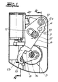
- einen Servo-Schloßhalter in Draufsicht ohne Gehäuseoberteil,
- Fig. 2
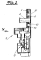
- einen Schnitt AA durch den Gegenstand nach
Fig. 1 , - Fig. 3
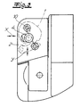
- den Gegenstand nach
Fig. 2 in Ansicht des Pfeiles X, - Fig. 4
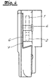
- den Gegenstand nach
Fig. 3 in Seitenansicht, - Fig. 5
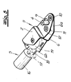
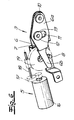
- die wesentlichen Bestandteile eines Servo-Schloßhalters in perspektivischer Darstellung und
- Fig. 6
- den Gegenstand nach
Fig. 5 in Ansicht von einer anderen Seite.
- Fig. 1
- a servo lock holder in plan view without housing top,
- Fig. 2
- a section AA through the object after
Fig. 1 . - Fig. 3
- the object after
Fig. 2 in view of the arrow X, - Fig. 4
- the object after
Fig. 3 in side view, - Fig. 5
- the essential components of a servo-lock holder in perspective and
- Fig. 6
- the object after
Fig. 5 in view from another side.
In den Figuren ist ein Kraftfahrzeugtürverschluß dargestellt, der in seinem grundsätzlichen Aufbau ein türseitiges Türschloß mit angedeuteter Drehfalle 1 und Sperrklinke 2 sowie einen türrahmenseitigen Servo-Schloßhalter 3 mit einem verstellbaren Schließbolzen 4 aufweist, welcher die Fahrzeugtür bei den Schließbolzen 4 in Schließstellung umgreifender Drehfalle 1 aus einer Vorschließstellung in eine Endschließstellung überführt. Auf den Schließbolzen 4 arbeitet eine Antriebseinrichtung 5 unter Zwischenschaltung einer Betätigungsschwinge 6. Die Betätigungsschwinge 6 ist mit ihrem einen Schwingenende 6a auf einer Montageplatte 7 schwenkbar gelagert. Dabei erfolgt eine Verbindung der Betätigungsschwinge 6 mit der Montageplatte 7 im Rahmen des Ausführungsbeispiels mittels Hohlbolzen, die endseitig umgebördelt sind. Durch diese Hohlbolzen sind Befestigungsschrauben zum Anschluß an die Karosserie geführt.In the figures, a motor vehicle door lock is shown having in its basic structure a door-side door lock with
Die Montageplatte 7 wird an einem zugeordneten Türholm befestigt. Im Rahmen der Erfindung liegt es natürlich auch, die Montageplatte 7 und ein Karosseriebauteil einstückig auszuführen. Jedenfalls übernimmt die Montageplatte 7 primär die Aufgabe, für eine feste Verbindung zwischen der Antriebseinheit 5 und der Karosserie bzw. dem Türholm zu sorgen.The mounting
Das andere Schwingenende 6b der Betätigungsschwinge 6 ist von einem Betätigungsglied 8 beaufschlagt, welches von der Antriebseinrichtung 5 antreibbar ist. Der Schließbolzen 4 ist an der Betätigungsschwinge 6 befestigt und praktisch fliegend gelagert. Ferner ist der Schließbolzen 4 in einem vorgegebenen Abstand zu dem dem antriebsseitigen Schwingenende 6b abgewandten Schwingenende 6a auf der Betätigungsschwinge 6 angeordnet. Der Schließbolzen 4 ist durch die Montageplatte 7 hindurchgeführt. Die Montageplatte 7 weist ein in Bewegungsrichtung des Schließbolzens 4 verlaufendes Langloch 9 für den hin- und herbewegbaren Schließbolzen 4 auf. Der Schließbolzen 4 ist zwischen dem Schwenkpunkt 10 und einer Langlochführung 11 der Betätigungsschwinge 6 angeordnet.The
Insbesondere aus den
Die auftretende Auslenkung des Schließbolzens 4 in durch einen Doppelpfeil angedeutete Y-Richtung ist äußerst gering und beträgt nach dem Ausführungsbeispiel lediglich noch ca. 0,4 mm. Durch die Anordnung des Schwenkpunktes 10 der Betätigungsschwinge 6 und folglich eines Kreisbogenmittelpunktes möglichst weit außerhalb des Schließbolzens 4 sowie durch die Schwenkbewegung um einen relativ großen Radius gelingt überraschenderweise eine im wesentlichen lineare Bewegung des an der Betätigungsschwinge 6 befestigten Schließbolzens 4.The occurring deflection of the
Die Betätigungsschwinge 6 weist eine in Schwenkrichtung verlaufende Langlochführung 11 für den an der Montageplatte 7 befestigten Führungszapfen 12 auf. Der Führungszapfen 12 besitzt an seinem durch die Langlochführung 11 hindurchgeführten Zapfenende ein Auflager 13 für die Betätigungsschwinge 6. Die Betätigungsschwinge 6 ist von einer Feder 14, z. B. Flachspiralfeder beaufschlagt, welche die Betätigungsschwinge 6 ständig gegen das Betätigungsglied 8 drückt. Ferner ist die Betätigungsschwinge 6 als Hebel mit einem von der Feder 14 und dem Betätigungsglied 8 beaufschlagten schwanzartigen Hebelfortsatz 15 ausgebildet.The actuating
Die Antriebseinrichtung 5 weist einen Elektromotor 16 mit Getriebe 17 und eine Abtriebswelle 18 für ein Abtriebselement 19 mit dem Betätigungsglied 8 auf. Das Abtriebselement 19 ist als ein mit einer Schnecke auf der Abtriebswelle 18 kämmendes Zahnrad und das Betätigungsglied 8 als ein im Randbereich des Zahnrades angeordneter Steuerzapfen ausgebildet. Die Betätigungsschwinge 6 arbeitet auf einen Mikroschalter 20 zum Ein- und Ausschalten des Elektromotors 16.The
Claims (9)
- Motor vehicle door locking mechanism, with a door lock with rotary latch (1) and ratchet (2) and with a servo lock holder (3) with an adjustable locking pin (4) which transfers the vehicle door, with the rotary latch (1) encompassing the locking pin (4) in the locking position, from a pre-closing position into a final closing position, wherein:- a drive arrangement (5) operates on the locking pin (4) with interposition of an actuating rocker (6),- the actuating rocker (6) is swivellably mounted by its one rocker end (6a) on a mounting plate (7), and- the other rocker end (6b) of the actuating rocker (6) is acted upon by an actuating member (8) which is able to be driven by the drive arrangement (5), and wherein- the locking pin (4) is fastened directly on the actuating rocker (6) at a predetermined distance from the rocker end (6a), facing away from the rocker end (6b) on the drive side.
- Motor vehicle door locking mechanism according to Claim 1, characterized in that the locking pin (4) is guided through the mounting plate (7) and the mounting plate (7) has an oblong hole (9), running in the direction of movement of the locking pin (4), for the locking pin (4) which is movable to and fro.
- Motor vehicle door locking mechanism according to Claim 1 or 2, characterized in that the actuating rocker (6) has an oblong hole guide (11), running in the swivelling direction, for a guide pin (12) which is fastened on the mounting plate (7).
- Motor vehicle door locking mechanism according to Claim 3, characterized in that the guide pin (12) has on its pin end which is guided through the oblong hole guide (11) a bearing (13) for the actuating rocker (6).
- Motor vehicle door locking mechanism according to one of Claims 1 to 4, characterized in that the actuating rocker (6) is acted upon by a spring (14), e.g. a flat spiral spring, which presses the actuating rocker (6) constantly against the actuating member (8).
- Motor vehicle door locking mechanism according to Claim 5, characterized in that the actuating rocker (6) is driven as a lever with a lever extension (15) which is acted upon by the spring (14) and the actuating member (8).
- Motor vehicle door locking mechanism according to one of Claims 1 to 6, characterized in that the drive arrangement (5) has an electric motor (16) with gear (17), if applicable coupling and an output shaft (18) for an output element (19) with the actuating member (8).
- Motor vehicle door locking mechanism according to Claim 7, characterized in that the output element (19) is constructed as a toothed wheel meshing with a pinion or a worm on the output shaft, and the actuating member (8) is formed as a control pin arranged in the marginal region of the toothed wheel.
- Motor vehicle door locking mechanism according to one of Claims 1 to 8, characterized in that the actuating rocker (6) operates on a micro-switch (20) for switching the electric motor (16) on and off.
Applications Claiming Priority (2)
| Application Number | Priority Date | Filing Date | Title |
|---|---|---|---|
| DE19955883 | 1999-11-20 | ||
| DE19955883A DE19955883A1 (en) | 1999-11-20 | 1999-11-20 | Motor vehicle door lock |
Publications (3)
| Publication Number | Publication Date |
|---|---|
| EP1101886A2 EP1101886A2 (en) | 2001-05-23 |
| EP1101886A3 EP1101886A3 (en) | 2002-09-04 |
| EP1101886B1 true EP1101886B1 (en) | 2010-01-20 |
Family
ID=7929739
Family Applications (1)
| Application Number | Title | Priority Date | Filing Date |
|---|---|---|---|
| EP00124591A Expired - Lifetime EP1101886B1 (en) | 1999-11-20 | 2000-11-10 | Motor vehicle door lock |
Country Status (4)
| Country | Link |
|---|---|
| US (1) | US6540270B1 (en) |
| EP (1) | EP1101886B1 (en) |
| AT (1) | ATE455915T1 (en) |
| DE (2) | DE19955883A1 (en) |
Families Citing this family (28)
| Publication number | Priority date | Publication date | Assignee | Title |
|---|---|---|---|---|
| DE19934753B4 (en) * | 1998-07-23 | 2006-09-07 | Ohi Seisakusho Co., Ltd., Yokohama | Electric lid closing device |
| DE10128608A1 (en) * | 2001-06-13 | 2003-07-03 | Valeo Sicherheitssysteme Gmbh | Locking aid for locking a vehicle door |
| DE10140385B4 (en) * | 2001-08-23 | 2012-06-21 | Kiekert Ag | Servo lock holder for a door lock, in particular motor vehicle door lock |
| DE10235608C5 (en) * | 2002-08-02 | 2014-07-31 | Valeo Sicherheitssysteme Gmbh | closing device |
| JP3550141B2 (en) * | 2002-09-13 | 2004-08-04 | 三井金属鉱業株式会社 | Drives and door closers |
| DE10318796B4 (en) * | 2002-12-24 | 2008-04-30 | BÖCO Böddecker & Co. GmbH & Co. KG | hood closure |
| DE10316763A1 (en) * | 2003-04-10 | 2004-10-28 | Siemens Ag | Closure aid for vehicle doors includes drive operating on locking component via mechanism including dead point in path of motion between two positions |
| DE10321275B4 (en) * | 2003-05-13 | 2017-07-27 | Bayerische Motoren Werke Aktiengesellschaft | Lock arrangement for a vehicle |
| DE10321262A1 (en) * | 2003-05-13 | 2004-12-02 | Bayerische Motoren Werke Ag | Lock for vehicle door, has stop that is contacted by guide section when guide section is urged by spring due to closing pin engaging rotating case |
| DE10322122C5 (en) * | 2003-05-16 | 2010-11-11 | Kiekert Ag | motor vehicle |
| DE102004010647A1 (en) * | 2004-03-01 | 2005-09-22 | Volkswagen Ag | Operational auxiliary device for opening and closing a motor vehicle bonnet or rear boot with ejector and tighening devices having common drive |
| DE102004013357B3 (en) * | 2004-03-17 | 2005-09-29 | Kiekert Ag | Motor vehicle without B-pillar has facility whereby before and/or during opening of one door the other door is adjusted by servo closing unit by predetermined amount and occupies seal relieving position to protect seal against damage |
| DE102004016867A1 (en) * | 2004-04-03 | 2005-10-20 | Brose Schliesssysteme Gmbh | Lock wedge drive assembly for a motor vehicle lock |
| DE102004033035A1 (en) | 2004-07-07 | 2006-02-02 | Huf Hülsbeck & Fürst Gmbh & Co. Kg | Device for closing an open flap or door of a vehicle to the body |
| DE102004043661A1 (en) * | 2004-09-07 | 2006-03-09 | Siemens Ag | Closing frame-drive arrangement for door or flap of motor vehicle, has closing frame plate supported at body of motor vehicle and swivellable around its axis, and closing frame arranged at a distance from frame plate |
| WO2006060921A1 (en) * | 2004-12-09 | 2006-06-15 | Magna Closures Inc. | Lost motion cam actuating device |
| JP2008530407A (en) * | 2005-02-18 | 2008-08-07 | メリター・テクノロジー・インコーポレーテッド | Latch assembly |
| DE102005044548B4 (en) * | 2005-09-17 | 2007-12-13 | Daimlerchrysler Ag | Locking device with a closing aid for a motor vehicle |
| DE102005062998B4 (en) * | 2005-12-30 | 2019-04-25 | Kiekert Ag | Motor vehicle door lock |
| US8068959B2 (en) * | 2007-08-07 | 2011-11-29 | Ford Global Technologies, Llc | Vehicle door active and passive control device |
| DE102008010272B4 (en) * | 2008-02-21 | 2013-08-22 | Thermo Electron Led Gmbh | Cover closure for housing cover of laboratory equipment and the like |
| US8326497B2 (en) * | 2009-01-12 | 2012-12-04 | Ford Global Technologies, Llc | Vehicle door close/open assist and anti-slam device |
| US9163437B1 (en) * | 2012-05-24 | 2015-10-20 | Barry G. Lawrence | Tilt window latch and method |
| DE102013019938A1 (en) * | 2013-10-14 | 2015-04-16 | Kiekert Ag | Locking unit for a motor vehicle |
| DE102016218299A1 (en) * | 2015-09-29 | 2017-03-30 | Magna Closures S.P.A. | One-motor locking arrangement with power-tightening and power-unlocking with a soft opening function |
| US11512505B2 (en) | 2016-03-31 | 2022-11-29 | Trimark Corporation | Motorized movable strike for a vehicle door |
| DE102017009902A1 (en) | 2017-10-24 | 2019-04-25 | Daimler Ag | Lock actuator with emergency opening function |
| US20190119959A1 (en) * | 2017-10-25 | 2019-04-25 | Nio Usa, Inc. | Latch with adjustable primary/final position |
Family Cites Families (15)
| Publication number | Priority date | Publication date | Assignee | Title |
|---|---|---|---|---|
| US3422572A (en) * | 1966-09-21 | 1969-01-21 | Gen Motors Corp | Vehicle body closure operator |
| FR2518620A1 (en) * | 1981-12-22 | 1983-06-24 | Peugeot Aciers Et Outillage | PIVOTING LOCK, IN PARTICULAR FOR A MOTOR VEHICLE |
| DE3401842A1 (en) | 1984-01-20 | 1985-08-01 | Erich 8650 Kulmbach Pöhlmann | Motor-vehicle door lock, bonnet lock or the like |
| US4707007A (en) * | 1985-02-07 | 1987-11-17 | Honda Giken Kogyo Kabushiki Kaisha | Striker means for automotive door latch assembly |
| FR2586744B1 (en) * | 1985-09-05 | 1987-12-04 | Mecanismes Comp Ind De | LOCK WITH ELECTRIC OPENING AND CLOSING, PARTICULARLY FOR MOTOR VEHICLE DOORS |
| DE3721963C1 (en) | 1987-07-03 | 1988-10-13 | Kiekert Gmbh Co Kg | Motor-vehicle door fastening |
| US5004280A (en) * | 1989-03-03 | 1991-04-02 | Itt Corporation | Variable power drive for sliding door |
| JP2556789B2 (en) * | 1991-03-29 | 1996-11-20 | 株式会社大井製作所 | Door lock locking / unlocking operation device |
| DE4210893A1 (en) | 1992-04-02 | 1993-10-07 | Vdo Schindling | Lock for motor vehicle door - has locking pin with eccentric middle part which engages slot in pivoted catch |
| DE4410712A1 (en) | 1993-04-08 | 1994-10-13 | Volkswagen Ag | Power-operated door-closing device, especially for motor vehicles |
| WO1997022771A1 (en) * | 1995-12-20 | 1997-06-26 | Itt Automotive Electrical Systems, Inc. | Power striker with inertially activated impact cycle |
| DE19614122B4 (en) * | 1996-04-11 | 2006-04-27 | Brose Schließsysteme GmbH & Co.KG | Motor vehicle flap lock or door lock |
| DE19638700C2 (en) * | 1996-09-21 | 1999-05-27 | Kiekert Ag | Motor vehicle door lock with child safety system |
| DE19710531B4 (en) * | 1997-03-14 | 2007-01-18 | Brose Schließsysteme GmbH & Co.KG | Motor vehicle door lock |
| DE19961247A1 (en) * | 1999-02-17 | 2000-08-24 | Huf Huelsbeck & Fuerst Gmbh | Door lock, especially for motor vehicle, having force storage element for pulling latch from trap, both in normal case, as well as in special case, e.g. at crash |
-
1999
- 1999-11-20 DE DE19955883A patent/DE19955883A1/en not_active Withdrawn
-
2000
- 2000-11-10 EP EP00124591A patent/EP1101886B1/en not_active Expired - Lifetime
- 2000-11-10 DE DE50015850T patent/DE50015850D1/en not_active Expired - Lifetime
- 2000-11-10 AT AT00124591T patent/ATE455915T1/en not_active IP Right Cessation
- 2000-11-20 US US09/716,827 patent/US6540270B1/en not_active Expired - Lifetime
Also Published As
| Publication number | Publication date |
|---|---|
| EP1101886A3 (en) | 2002-09-04 |
| DE50015850D1 (en) | 2010-03-11 |
| US6540270B1 (en) | 2003-04-01 |
| EP1101886A2 (en) | 2001-05-23 |
| ATE455915T1 (en) | 2010-02-15 |
| DE19955883A1 (en) | 2001-05-31 |
Similar Documents
| Publication | Publication Date | Title |
|---|---|---|
| EP1101886B1 (en) | Motor vehicle door lock | |
| EP2342405B1 (en) | Motor vehicle lock | |
| WO2019076398A1 (en) | Opening apparatus for a motor vehicle door | |
| EP1550784B1 (en) | Striker drive assembly for a motor vehicle door lock | |
| DE19737996C2 (en) | Striker drive assembly for a motor vehicle door lock or the like. | |
| WO2015024555A1 (en) | Motor vehicle door lock | |
| EP2291571A1 (en) | Closing device comprising a detent spring | |
| DE2912141A1 (en) | DRIVE FOR ADJUSTING A LINK, ESPECIALLY A COMPONENT PART OF A MOTOR VEHICLE | |
| EP2987931B1 (en) | Motor vehicle lock | |
| DE19616655A1 (en) | Device for opening and closing tailgate of vehicle | |
| EP2166181B1 (en) | Control drive for a vehicle lock | |
| DE10140385B4 (en) | Servo lock holder for a door lock, in particular motor vehicle door lock | |
| EP0940531B1 (en) | Closing assitance device for doors, bonnets and tailgates of a vehicle | |
| EP1865130B1 (en) | Unbolting assembly of a window, door or similar | |
| DE102006011085A1 (en) | Door opener, has drive unit that is formed such that outer interference is adjusted by locking plate for releasing door latch against spring pre-tensioning, where door latch latches in plate during closing of door by pre-tensioning | |
| DE4407912C2 (en) | Electromechanical lock | |
| DE102005035952B4 (en) | Device for opening and closing windows and doors | |
| EP1498562B1 (en) | Locking device | |
| EP1057955B1 (en) | Door locking system, particularly for cab doors of motor vehicles, such as mobile home | |
| DE10251375A1 (en) | Locking aid for locking a vehicle door | |
| DE102005062998A1 (en) | A method for sliding the locking bolt of a motor vehicle door lock has an electric motor driving a crank mechanism which pivots a plate to which the bolt is fixed about a centre of the lock housing | |
| EP1449995B1 (en) | Espagnolette lock with motor drive unit | |
| EP1580360B1 (en) | Actuator for motor vehicles | |
| EP2320013B1 (en) | Fitting with a reversing gear | |
| EP0685621A1 (en) | Locking device for an automatically actuated door |
Legal Events
| Date | Code | Title | Description |
|---|---|---|---|
| PUAI | Public reference made under article 153(3) epc to a published international application that has entered the european phase |
Free format text: ORIGINAL CODE: 0009012 |
|
| AK | Designated contracting states |
Kind code of ref document: A2 Designated state(s): AT BE CH CY DE DK ES FI FR GB GR IE IT LI LU MC NL PT SE TR |
|
| AX | Request for extension of the european patent |
Free format text: AL;LT;LV;MK;RO;SI |
|
| PUAL | Search report despatched |
Free format text: ORIGINAL CODE: 0009013 |
|
| AK | Designated contracting states |
Kind code of ref document: A3 Designated state(s): AT BE CH CY DE DK ES FI FR GB GR IE IT LI LU MC NL PT SE TR |
|
| AX | Request for extension of the european patent |
Free format text: AL;LT;LV;MK;RO;SI |
|
| RIN1 | Information on inventor provided before grant (corrected) |
Inventor name: REDDMANN, UWE |
|
| 17P | Request for examination filed |
Effective date: 20030221 |
|
| AKX | Designation fees paid |
Designated state(s): AT BE CH CY DE DK ES FI FR GB GR IE IT LI LU MC NL PT SE TR |
|
| 17Q | First examination report despatched |
Effective date: 20050610 |
|
| 17Q | First examination report despatched |
Effective date: 20050610 |
|
| GRAP | Despatch of communication of intention to grant a patent |
Free format text: ORIGINAL CODE: EPIDOSNIGR1 |
|
| GRAS | Grant fee paid |
Free format text: ORIGINAL CODE: EPIDOSNIGR3 |
|
| GRAA | (expected) grant |
Free format text: ORIGINAL CODE: 0009210 |
|
| AK | Designated contracting states |
Kind code of ref document: B1 Designated state(s): AT BE CH CY DE DK ES FI FR GB GR IE IT LI LU MC NL PT SE TR |
|
| REG | Reference to a national code |
Ref country code: GB Ref legal event code: FG4D Free format text: NOT ENGLISH |
|
| REG | Reference to a national code |
Ref country code: CH Ref legal event code: EP |
|
| REG | Reference to a national code |
Ref country code: IE Ref legal event code: FG4D |
|
| REF | Corresponds to: |
Ref document number: 50015850 Country of ref document: DE Date of ref document: 20100311 Kind code of ref document: P |
|
| REG | Reference to a national code |
Ref country code: NL Ref legal event code: VDEP Effective date: 20100120 |
|
| PG25 | Lapsed in a contracting state [announced via postgrant information from national office to epo] |
Ref country code: ES Free format text: LAPSE BECAUSE OF FAILURE TO SUBMIT A TRANSLATION OF THE DESCRIPTION OR TO PAY THE FEE WITHIN THE PRESCRIBED TIME-LIMIT Effective date: 20100501 Ref country code: NL Free format text: LAPSE BECAUSE OF FAILURE TO SUBMIT A TRANSLATION OF THE DESCRIPTION OR TO PAY THE FEE WITHIN THE PRESCRIBED TIME-LIMIT Effective date: 20100120 Ref country code: PT Free format text: LAPSE BECAUSE OF FAILURE TO SUBMIT A TRANSLATION OF THE DESCRIPTION OR TO PAY THE FEE WITHIN THE PRESCRIBED TIME-LIMIT Effective date: 20100520 |
|
| REG | Reference to a national code |
Ref country code: IE Ref legal event code: FD4D |
|
| PG25 | Lapsed in a contracting state [announced via postgrant information from national office to epo] |
Ref country code: FI Free format text: LAPSE BECAUSE OF FAILURE TO SUBMIT A TRANSLATION OF THE DESCRIPTION OR TO PAY THE FEE WITHIN THE PRESCRIBED TIME-LIMIT Effective date: 20100120 |
|
| PG25 | Lapsed in a contracting state [announced via postgrant information from national office to epo] |
Ref country code: GR Free format text: LAPSE BECAUSE OF FAILURE TO SUBMIT A TRANSLATION OF THE DESCRIPTION OR TO PAY THE FEE WITHIN THE PRESCRIBED TIME-LIMIT Effective date: 20100421 Ref country code: IE Free format text: LAPSE BECAUSE OF FAILURE TO SUBMIT A TRANSLATION OF THE DESCRIPTION OR TO PAY THE FEE WITHIN THE PRESCRIBED TIME-LIMIT Effective date: 20100120 Ref country code: SE Free format text: LAPSE BECAUSE OF FAILURE TO SUBMIT A TRANSLATION OF THE DESCRIPTION OR TO PAY THE FEE WITHIN THE PRESCRIBED TIME-LIMIT Effective date: 20100120 Ref country code: CY Free format text: LAPSE BECAUSE OF FAILURE TO SUBMIT A TRANSLATION OF THE DESCRIPTION OR TO PAY THE FEE WITHIN THE PRESCRIBED TIME-LIMIT Effective date: 20100120 |
|
| PLBE | No opposition filed within time limit |
Free format text: ORIGINAL CODE: 0009261 |
|
| STAA | Information on the status of an ep patent application or granted ep patent |
Free format text: STATUS: NO OPPOSITION FILED WITHIN TIME LIMIT |
|
| 26N | No opposition filed |
Effective date: 20101021 |
|
| PG25 | Lapsed in a contracting state [announced via postgrant information from national office to epo] |
Ref country code: DK Free format text: LAPSE BECAUSE OF FAILURE TO SUBMIT A TRANSLATION OF THE DESCRIPTION OR TO PAY THE FEE WITHIN THE PRESCRIBED TIME-LIMIT Effective date: 20100120 |
|
| PG25 | Lapsed in a contracting state [announced via postgrant information from national office to epo] |
Ref country code: IT Free format text: LAPSE BECAUSE OF FAILURE TO SUBMIT A TRANSLATION OF THE DESCRIPTION OR TO PAY THE FEE WITHIN THE PRESCRIBED TIME-LIMIT Effective date: 20100120 |
|
| BERE | Be: lapsed |
Owner name: KIEKERT A.G. Effective date: 20101130 |
|
| PG25 | Lapsed in a contracting state [announced via postgrant information from national office to epo] |
Ref country code: MC Free format text: LAPSE BECAUSE OF NON-PAYMENT OF DUE FEES Effective date: 20101130 |
|
| REG | Reference to a national code |
Ref country code: CH Ref legal event code: PL |
|
| GBPC | Gb: european patent ceased through non-payment of renewal fee |
Effective date: 20101110 |
|
| PG25 | Lapsed in a contracting state [announced via postgrant information from national office to epo] |
Ref country code: CH Free format text: LAPSE BECAUSE OF NON-PAYMENT OF DUE FEES Effective date: 20101130 Ref country code: LI Free format text: LAPSE BECAUSE OF NON-PAYMENT OF DUE FEES Effective date: 20101130 |
|
| PG25 | Lapsed in a contracting state [announced via postgrant information from national office to epo] |
Ref country code: BE Free format text: LAPSE BECAUSE OF NON-PAYMENT OF DUE FEES Effective date: 20101130 |
|
| PG25 | Lapsed in a contracting state [announced via postgrant information from national office to epo] |
Ref country code: GB Free format text: LAPSE BECAUSE OF NON-PAYMENT OF DUE FEES Effective date: 20101110 |
|
| REG | Reference to a national code |
Ref country code: AT Ref legal event code: MM01 Ref document number: 455915 Country of ref document: AT Kind code of ref document: T Effective date: 20101110 |
|
| PG25 | Lapsed in a contracting state [announced via postgrant information from national office to epo] |
Ref country code: AT Free format text: LAPSE BECAUSE OF NON-PAYMENT OF DUE FEES Effective date: 20101110 |
|
| PG25 | Lapsed in a contracting state [announced via postgrant information from national office to epo] |
Ref country code: LU Free format text: LAPSE BECAUSE OF NON-PAYMENT OF DUE FEES Effective date: 20101110 |
|
| PG25 | Lapsed in a contracting state [announced via postgrant information from national office to epo] |
Ref country code: TR Free format text: LAPSE BECAUSE OF FAILURE TO SUBMIT A TRANSLATION OF THE DESCRIPTION OR TO PAY THE FEE WITHIN THE PRESCRIBED TIME-LIMIT Effective date: 20100120 |
|
| REG | Reference to a national code |
Ref country code: FR Ref legal event code: PLFP Year of fee payment: 16 |
|
| REG | Reference to a national code |
Ref country code: FR Ref legal event code: PLFP Year of fee payment: 17 |
|
| REG | Reference to a national code |
Ref country code: FR Ref legal event code: PLFP Year of fee payment: 18 |
|
| PGFP | Annual fee paid to national office [announced via postgrant information from national office to epo] |
Ref country code: DE Payment date: 20191125 Year of fee payment: 20 |
|
| PGFP | Annual fee paid to national office [announced via postgrant information from national office to epo] |
Ref country code: FR Payment date: 20191121 Year of fee payment: 20 |
|
| REG | Reference to a national code |
Ref country code: DE Ref legal event code: R071 Ref document number: 50015850 Country of ref document: DE |