EP1026916A2 - Système automatique pour identifier une connexion de télécommunication - Google Patents
Système automatique pour identifier une connexion de télécommunication Download PDFInfo
- Publication number
- EP1026916A2 EP1026916A2 EP00300566A EP00300566A EP1026916A2 EP 1026916 A2 EP1026916 A2 EP 1026916A2 EP 00300566 A EP00300566 A EP 00300566A EP 00300566 A EP00300566 A EP 00300566A EP 1026916 A2 EP1026916 A2 EP 1026916A2
- Authority
- EP
- European Patent Office
- Prior art keywords
- network
- port
- link
- ports
- identification
- Prior art date
- Legal status (The legal status is an assumption and is not a legal conclusion. Google has not performed a legal analysis and makes no representation as to the accuracy of the status listed.)
- Withdrawn
Links
- 238000000034 method Methods 0.000 claims abstract description 91
- 238000004891 communication Methods 0.000 claims abstract description 21
- 238000012986 modification Methods 0.000 claims abstract description 11
- 230000004048 modification Effects 0.000 claims abstract description 11
- 230000000977 initiatory effect Effects 0.000 claims abstract description 8
- 230000005540 biological transmission Effects 0.000 claims description 21
- 230000008447 perception Effects 0.000 claims description 11
- RGNPBRKPHBKNKX-UHFFFAOYSA-N hexaflumuron Chemical group C1=C(Cl)C(OC(F)(F)C(F)F)=C(Cl)C=C1NC(=O)NC(=O)C1=C(F)C=CC=C1F RGNPBRKPHBKNKX-UHFFFAOYSA-N 0.000 claims description 10
- 230000003287 optical effect Effects 0.000 claims description 7
- 230000002457 bidirectional effect Effects 0.000 claims description 5
- 238000012545 processing Methods 0.000 claims description 5
- 238000013507 mapping Methods 0.000 claims description 2
- 230000004913 activation Effects 0.000 claims 1
- 230000008569 process Effects 0.000 abstract description 71
- 238000010586 diagram Methods 0.000 description 12
- 239000013307 optical fiber Substances 0.000 description 6
- 238000012217 deletion Methods 0.000 description 3
- 230000037430 deletion Effects 0.000 description 3
- 230000001960 triggered effect Effects 0.000 description 2
- 238000013459 approach Methods 0.000 description 1
- 230000008859 change Effects 0.000 description 1
- 230000001427 coherent effect Effects 0.000 description 1
- 239000000835 fiber Substances 0.000 description 1
- 230000006855 networking Effects 0.000 description 1
- 238000012360 testing method Methods 0.000 description 1
Images


Classifications
-
- H—ELECTRICITY
- H04—ELECTRIC COMMUNICATION TECHNIQUE
- H04L—TRANSMISSION OF DIGITAL INFORMATION, e.g. TELEGRAPHIC COMMUNICATION
- H04L45/00—Routing or path finding of packets in data switching networks
- H04L45/26—Route discovery packet
-
- H—ELECTRICITY
- H04—ELECTRIC COMMUNICATION TECHNIQUE
- H04L—TRANSMISSION OF DIGITAL INFORMATION, e.g. TELEGRAPHIC COMMUNICATION
- H04L41/00—Arrangements for maintenance, administration or management of data switching networks, e.g. of packet switching networks
- H04L41/12—Discovery or management of network topologies
-
- H—ELECTRICITY
- H04—ELECTRIC COMMUNICATION TECHNIQUE
- H04L—TRANSMISSION OF DIGITAL INFORMATION, e.g. TELEGRAPHIC COMMUNICATION
- H04L45/00—Routing or path finding of packets in data switching networks
- H04L45/02—Topology update or discovery
-
- H—ELECTRICITY
- H04—ELECTRIC COMMUNICATION TECHNIQUE
- H04Q—SELECTING
- H04Q3/00—Selecting arrangements
- H04Q3/64—Distributing or queueing
- H04Q3/66—Traffic distributors
- H04Q3/665—Circuit arrangements therefor
-
- H—ELECTRICITY
- H04—ELECTRIC COMMUNICATION TECHNIQUE
- H04Q—SELECTING
- H04Q2213/00—Indexing scheme relating to selecting arrangements in general and for multiplex systems
- H04Q2213/13097—Numbering, addressing
-
- H—ELECTRICITY
- H04—ELECTRIC COMMUNICATION TECHNIQUE
- H04Q—SELECTING
- H04Q2213/00—Indexing scheme relating to selecting arrangements in general and for multiplex systems
- H04Q2213/13202—Network termination [NT]
-
- H—ELECTRICITY
- H04—ELECTRIC COMMUNICATION TECHNIQUE
- H04Q—SELECTING
- H04Q2213/00—Indexing scheme relating to selecting arrangements in general and for multiplex systems
- H04Q2213/13204—Protocols
-
- H—ELECTRICITY
- H04—ELECTRIC COMMUNICATION TECHNIQUE
- H04Q—SELECTING
- H04Q2213/00—Indexing scheme relating to selecting arrangements in general and for multiplex systems
- H04Q2213/13209—ISDN
-
- H—ELECTRICITY
- H04—ELECTRIC COMMUNICATION TECHNIQUE
- H04Q—SELECTING
- H04Q2213/00—Indexing scheme relating to selecting arrangements in general and for multiplex systems
- H04Q2213/13352—Self-routing networks, real-time routing
-
- H—ELECTRICITY
- H04—ELECTRIC COMMUNICATION TECHNIQUE
- H04Q—SELECTING
- H04Q2213/00—Indexing scheme relating to selecting arrangements in general and for multiplex systems
- H04Q2213/13367—Hierarchical multiplexing, add-drop multiplexing
Definitions
- the invention relates to telecommunications networks and, more particularly, to the identification of point-to-point links within a telecommunications system.
- every telecommunications network begins with a single link.
- Each link connects two telecommunications network elements, from individual port to individual port, through a specific transmission medium, such as an electrical cable, an optical fiber, a radio frequency (RF) channel, or other transmission medium.
- Each network element may be linked to one or more other network elements through a plurality of ports, each of which may include an electrical, optical, or RF interface.
- RF radio frequency
- a telecommunications network management system typically must be able to identify each link within the system. That is, the network management system typically accumulates the point-to-point connectivity information between the various ports within the system to form a network map.
- the network map portrays the "cabling", whether optical, electrical, or otherwise, between all the ports within all network elements within the system.
- Such networks typically include a very large number of network elements, an even larger number of ports, and, as noted above, in conventional telecommunications networks, each of the links is identified manually. The process of identifying each of the network elements could be a daunting task.
- a network management system that automatically determines the connectivity path for each link under its purview would therefore be highly desirable.
- a telecommunications network in accordance with the principles of the invention includes one or more controllers that automatically determine the physical interconnectivity between at least two ports adjacently situated in different network elements.
- Each end-point, that is, each port has a unique identification.
- each port's associated controller upon the occasion of a network modification, such as the addition of a port to the network, the initiation of a port, or reconfiguration of a link, each port's associated controller transmits an identification message to the port's adjacently neighboring port.
- the identification message includes the transmitting, or local, port's identification and the presumed identification of the adjacent receiving, or remote, port's identification.
- the controller associated with the remote port transmits an identification message containing the "remote port's view", that is, the local and remote port identifications, from the perspective of the remote port, to the local port.
- the link is identified, in that one or more controllers have determined the interconnectivity of the two ports that comprise the link.
- the controllers retain this link identification information until some change in the network configuration initiates a re-identification. If, however, the identification messages from the two neighboring ports do not agree, the controller associated with the local port will update the "remote" potion of its identification message and re-send the message to its neighbor as an acknowledgement of the updated remote port identification information. Once the link identification is established, this interconnectivity data is maintained until such time as a neighboring port sends a link identification message, or the port's local identification is modified.
- link identification includes the target identifier and network address of each network element and, consequently, the automatic link identification process may be employed to identify the network elements within a telecommunications network.
- optical fibers are employed in a telecommunications network that may be compatible with SONET or SDH optical telecommunications systems standards.
- a telecommunications network in accordance with the principles of the invention may employ any of a variety of topologies, the illustrative embodiment employs a bidirectional line switched ring (BLSR) topology.
- BLSR line switched ring
- the "discovery" of link identification takes place at the Open Systems Interconnection (OSI) data link layer and employs the link access procedure for ISDN D-channel (LAPD) protocol.
- OSI Open Systems Interconnection
- LAPD ISDN D-channel
- a network in accordance with the principles of the invention may employ a network management system to accumulate the above link identification information for each active link in the network, to thereby create a network map.
- the network management system may be a distributed system, in that each element within the network, employing its own controller, may develop a network map, or network topology Alternatively, in a telecommunications system that employs a centralized network management system a network management system controller may interrogate various network elements in order to obtain the link information and then to develop the network map.
- the network map may be employed by the network management system to allocate, or provision, network resources and to properly respond to network alarms.
- a telecommunications network in accordance with the principles of the present invention includes one or more controllers that automatically determine the physical interconnectivity between individual ports within the telecommunications network.
- An identification message including the identification information related to both the sending and receiving ports, is transmitted from each port to its adjacent neighbor and, when the two ports converge on a view of their interconnectivity, that interconnectivity information is stored for each port within the one or more controllers.
- a network management system may produce an accurate network map that may be employed for provisioning network resources and for responding to network alarms.
- the conceptual block diagram of Figure 1 illustrates a telecommunications network 100 in accordance with the principles of the present invention.
- the network includes a plurality of network elements (NEs) interconnected through communications links.
- Each communications link includes a pair of ports and a transmission path through which they are connected.
- the transmission paths may be embodied by such media as wire cable, optical fiber, or an RF transmission path, but may be referred to hereinafter as a cable or a fiber for the sake of convenience.
- network element will generally be used to refer to any one of a variety of telecommunications equipment types, such as a multiplexer, an add/drop multiplexer, a switch, or other piece of telecommunications equipment that may act as a node within a telecommunications network
- Each NE typically includes a plurality of ports, each of which may be connected through a path, such as an electrical cable or an optical fiber, for example, to another port within another NE.
- a network link essentially, comprises this combination of two ports connected through a communications path.
- a network may include one or more such network links.
- the network may be viewed as a combination of nodes, each of which may be automatically identified, as described in the provisional United States patent application filed by the same inventor as the current application on December 3, 1998, having a serial number of 60/110724, and entitled, "Automatic Node Identification Assignment in Ring Networks", which is hereby incorporated by reference in its entirety.
- NE-A 102 includes four ports. p1,p2, p3, and p4. Each of the ports p1, p2, p3 and p4 may comprise electrical or optical interface circuitry and data may be transmitted or received through each of the ports.
- a network link, over which data may be transmitted and received, may be formed by attaching a port within one network element to a port within another network element through a transmission path such as an electrical cable or an optical fiber.
- a controller 104 is associated with the NE-A 102 and may be physically co-located within the same package as the NE-A 102 or may be located separately, with a communications path provided to the NE-A 102.
- the controller 104 may take any of a variety of forms, such as an embedded controller, dedicated to the associated network element, or it may be a controller such as a DACScan 2000 TM as described in "Understanding SONET/SDH Standards and Applications, Ming-Chwan Chow, pp. 7-1 through 7-40, Andan Publisher, New Jersey, 1995, which is hereby incorporated by reference.
- Each network element, NE-B 106, NE-C 108, NE-D 110 may include a controller (not shown), and a plurality of ports. Ports p5-p8, p9-p12, and p13-p16 are respectively contained within network elements NE-B, NE-C, and NE-D. Port p1 of NE-A is connected through transmission path 112 to port p6 of NE-B and port p2 of NE-A is connected through transmission path 114 to port p5 of NE-B.
- each of the transmission paths 112-126 might be an optical fiber and the illustrated network may be implemented, for example, as a bidirectional line switched ring (BLSR).
- SONET networks and bidirectional line switched rings are known and are discussed, for example, in "Understanding SONET/SDH Standards and Applications, Ming-Chwan Chow, pp. 7-1 through 7-40.
- the controller 104 under various circumstances including network modifications such as the addition of a port to the network, the initiation of a port, or the reconfiguration of a link, initiates the transmission of identification messages from each of the ports to the respective ports to which they are connected.
- the identification message provides an indication of the transmitting port's, "view", “perception”, or “presumption” of the link's configuration.
- the transmitting port's view of the link configuration is compared to the receiving port's view of the link configuration.
- the transmitting and receiving ports exchange their views of the link configuration until their views converge (not withstanding the somewhat anthropomorphic terminology, there is no implication that the ports are, or directly rely upon for their proper operations, sentient beings).
- the identification message include the information set forth in the illustrative conceptual diagram of Figure 2.
- the transmitting port includes its own port identity and it's best estimate of the receiving port's identity. This estimate may be based upon previously received messages from the receiving port or other sources, or the field may be left "blank"
- the link identification message 200 includes local end node 202 and remote end node 204 information segments.
- the local end node segment includes a version number 206, a target identifier (TID) 208, a port identifier 210, and a network address 212.
- the target identifier is the symbolic name of the port's associated network element.
- the remote end node information segment 204 includes a version number 214, the presumed TID 216 associated with the remote port, the presumed port identification 218 of the remote port, and the network address 220 of the remote port's associated network element.
- this exchange of link information is event-driven, triggered by the creation of a link, by the reestablishment of a link connection with an adjacent network element, or by the modification of a port's identification, or the port's associated network element's network address or symbolic name.
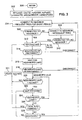
- the basic link identification process is set forth in the flow chart of Figure 3.
- the process begins in step 300 and proceeds from there to step 302 where the link identification information, as set forth in the block diagram representation of Figure 2, is initialized, with the presumed values for the local 202 and remote 204 end node data segments.
- the remote end node data segment 204 could be initialized to "unknown" values, for example.
- the process proceeds from step 302 to step 304 where an attempt is made to establish a connection between the local and remote ports. The attempt is repeated frequently until a connection is established or a predetermined period of time has elapsed. In either case, the process proceeds from step 304 to step 306, where it is determined whether the connection to the adjacent port has been established.
- step 308 If the connection has not been made, the process proceeds to step 308, where less frequent attempts to connect to the adjacent port are made.
- the association may be made at a data link layer and, in an illustrative OSI embodiment, the connection is made through an OSI data link layer employing the LAPD protocol. More specifically, the connection employs the AITS service of the LAPD protocol, which insures reliable communications for this critical step.
- step 310 it is determined whether a connection to the adjacent port has been established. If no connection has been made, the process returns to step 308. If the connection has been established the process proceeds, as it would from step 306 when a connection is established, to step 312, where the local port transmits its link identification information, e.g., the link identification message 200, to the remote port.
- link identification information e.g., the link identification message 200
- step 314 a test is performed to determine whether the transmission to the remote port has failed, has been successful, or the connection has been terminated. If the connection has been terminated, the process returns to step 304, and from there as previously described. If the transmission has failed, the process returns to step 312 to re-send the link identification message. If the transmission was successful, the process proceeds from step 314 to step 316, where the local port awaits the reception of a link identification message from the remote port. From step 316 the process proceeds to step 318 where it is determined whether the remote port's link identification message has arrived or, the connection to the remote port has been terminated. If the connection has been terminated the process proceeds to step 304, and from there as previously described.
- step 320 the remote and local link identification messages are compared, and, if they are not the same, the process proceeds to step 321, where the local port updates its link identification information. From step 321, the process returns to step 312 and proceeds from there as previously described. On the other hand, if the local and remote link identification messages are the same, the process proceeds from step 320 to step 322.
- step 322 a state is entered whereby the process essentially idles, awaiting an event, such as an update in the remote port's identification, modifications to the local port's identification, or the termination of the connection to the remote port. Other processes may be taking place in parallel at the same time, on the same controller or network management system.
- the process proceeds from step 322 to step 324 where it is determined whether the remote port's link identification message has been received and, if it has, the process returns to step 320 and proceeds from there as previously described. If the remote port's link identification message was not received, the process proceeds from step 324 to step 326 where it is determined whether local port identification information has been changed. If local port identification information has been modified, the process returns to step 321 and from there as previously described.
- step 328 it is determined whether the link to the remote port has been terminated and, if so, the process returns to step 304 and, from there as previously described. If the link to the remote port has not been terminated the process returns to step 322 and from there as previously described.
- the link identification information may be employed to form, with a network management system, for example, a network map.
- the network map could then be used to provision the bandwidth capacity of the various links within the network or to respond to network alarms by correlating network alarms and isolating failures. Additionally, the system could respond by re-routing data around a failed link, for example.
- the flow chart of Figure 4 sets illustrates the basic steps involved in creating a network map based upon the link identification information established according to the process described in the discussion related to the flow chart of Figure 3. Once the map is established, the resources referenced by the map may be allocated and modifications to the link information may be reflected in the map.
- step 400 The process of producing a network map begins in step 400 and proceeds from there to step 402 where link identification information, such as that established in the process described in relation to the flow chart of Figure 3, is gathered. From step 402 the process proceeds to step 404, where it is determined whether link identification information for all the links in the network has been gathered and, if not, the process returns to step 402. If link identification information for all the links within the network has been gathered, the process proceeds to step 406, where the network map is updated. This process involves organizing the link identification information gathered in step 402 into coherent map which depicts the point to point connection of each port in each network element within the network. The updating process may involve the revision of an existing map, or may be the initial creation of a network map.
- a network management system could develop a network map by accessing a single network element and tracing all the links with which that network element is associated to the opposite ends of the links. The links associated with network elements that incorporate these opposite ends may then be traced, and so on, until all links within the network are accounted for and included in the network map.
- step 408 the network map created in step 406, the map which relies upon link identification information obtained according to the process described in relation to the discussion of Figure 3, is employed to allocate the available network resources for the transmission of information throughout the network.
- step 410 the process awaits a link event that would affect the network map or provisioning. Should such an event occur, the process returns to step 402 and from there as previously described.
- link events might include the addition or deletion of a link, the modification of a link identification or an alarm that indicates the failure of a specific link. for example.
- the network may respond to any such link event to identify links, collect link identity information, update the network map and provision network resources accordingly.
- the process may idle in step 410 awaiting such an event or when the network manager is upgraded, for example, the process may proceed to end in step 412.
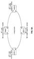
- FIG. 5A through 5C sets forth in greater detail an illustrative embodiment in accordance with the principles of the present invention of a method of producing a network map
- a SONET bidirectional line switched ring (BLSR) is used in the example of Figures 5A through 5C, but the inventive method is not restricted to SONET or BLSR topologies.
- the illustrative network mapping is an autonomous topology determination that relies upon information regarding the interconnectivity between adjacent nodes, or network elements, in a telecommunications network.
- This interconnectivity information that is, the identification of which port, and, consequently, which node, is connected to each port within a given network element, or node, is supplied as by the apparatus and process described in the discussion related to Figures 1 through 4.
- a timer may be set so that the network map may be updated at regular intervals.
- a BLSR network including four network elements, nodes A, B, C, and D is illustrated in the conceptual block diagram of Figure 5A.
- Port p6 of Node A is connected to port p4 of node B
- port p3 of node B is connected to port p4 of Node C
- port p3 of Node C is connected to port p2 of Node D
- port p1 of Node D is connected to port p5 of Node A.
- a port ID could be a combination of physical identifiers that correspond to the bay, shelf, slot, and port numbers for a given port.
- the network address for example, an OSI network entity title (NET) or TCP/IP address, name (TID) and system identification (SystemId) for each network element is listed next to the respective network element.
- the SystemId value is actually a component of the network address.
- the network address, name, and system identification for nodes A-D are, respectively, net1, net2, net3, and net4, node A, node B, node C, and node D, 123456 756283, 232323, and 325721.
- each port of each node transmits the above link identification information, as previously described, employing the OSI data link layer and the LAPD protocol in this illustrative embodiment.
- the table associated with node A indicates that port p5 (a local port) is connected to remote port p1 associated with a remote network address, NET, of net4 and remote name, TID, of node D.
- local port p6 is connected to a remote port p4 that has a network address, NET, net2 and name, TID, of node B.
- the above link identification information may be employed to determine the network topology, for example, as described in the discussion related to Figures 6 through 7D.
- the illustrative process is decentralized, in that the process is executed independently at each network element, or node.
- the topology determination process distributes the link identification information, gathered as described in the discussion related to Figures 1 through 4, from node to node, each direction around the ring, with each node appending its own link identification information and passing the information along.
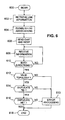
- the flow chart of Figure 6 depicts, in general terms, the process each node within the ring undergoes to determine the network topology.
- the process begins in step 600 and proceeds from there to step 602 where the node retrieves the previously obtained link identification information for each of its associated links.
- the network illustrated in the exemplary embodiments related to figures 5A through 7D have only two links associated with each node, each node may have several links, as in a multiply nested ring.
- step 604 the node establishes an OSI association with both its East and West neighbors.
- step 606 the node sends network information, including the local NET, the local East or West label associated with the transmitting port, and the link identification information, to its East and West neighbors. From step 606 the process proceeds to step 608 where the originating node waits to receive network information from the neighbors to which it has sent its own network information. When network information is received from another node the process proceeds to step 610 where the node determines whether it has received appended messages from its East and West neighbors. If it has not received messages from both directions, the process returns to step 608, where the node awaits the receipt of an appended message from the remaining neighbor node.
- a non-originating node would append its own data to a received message and pass the appended message to the opposite port. That is, if a non-originating node receives a message at its East port, it will add its information to the message, then transmit the message to its western neighbor. If the node (originating) determines in step 610 that it has received messages from both its neighbors, the process proceeds to step 612 where the gathered information is examined to determine the network topology and the resulting topology is examined to determine whether it is a valid topology.
- step 613 for error processing, which may include setting error flags and a renewed attempt at determining the network topology. From step 613 the process proceeds to end in step 618. If, in step 612, it is determined that the network topology is valid, the process proceeds to step 614 where it is determined whether any TIDs (network element names) have been duplicated. If TIDs have been duplicated in the information exchange, the process proceeds to the error processing of step 613, and from there as before. If no TIDs have been duplicated, the process proceeds to step 616 where it is determined whether any NETs (network element addresses) were duplicated in the information exchange. If any NETs have been duplicated; the process proceeds to the error processing of step 613 and from there as previously described. If no duplicate NETs are uncovered, the process proceeds from step 616 to end in step 618.
- TIDs network element names
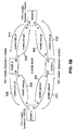
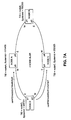
- FIG. 7A The conceptual block diagrams of Figures 7A through 7D illustrate the process of determining a network topology in an exemplary SONET BLSR network.
- the process begins in Figure 7A when node D, after establishing OSI associations with its East and West neighbors, transmits network information, to node A, using the East port of node D, that is port p1 and transmits network information to node C, using the West port of node D, port p2.
- the network information transmitted to nodes A and C includes node D's NET information, an indication of whether the transmitting port is an East or West port, and the link identification information.
- the information transmitted from Node D to node A therefore, includes net4/E/nodeD/p1/nodeA/p5, respectively the local NET, the local East or West label of the port, the local TID, local port ID, the remote TID, and the remote port ID.
- the information transmitted from node D to node C includes net4/W/nodeD/p2/nodeC/p3, respectively the local NET, the local East or West label of the port, the local TID, local port ID, the remote TID, and the remote port ID.
- Figure 7B illustrates the further step of the network topology determination whereby the nodes which received network information from node D proceed to append their information and transmitted the concatenated network identification information to the node which lies opposite the port at which they received the network identification information.
- node A since Node A has received a message at its west port port p5, from node D, after appending its own identification information to the message, node A transmits the message from its opposing, East, port to node B Similarly, since node C has received a message at its west port, port p3, from node D, after appending its own identification information to the message, node C transmits the message from its opposing, East, port to node B.
- node D When the originating node, node D, receives return messages from both directions, as depicted in Figure 7D, node D has a complete ring map of the BLSR, including ring node connectivity at the port interface, as well as the TIDs and NETs of all nodes on the ring.
- the network map, or topology, thus discovered may be employed to adjust to alarm conditions. For example, should an alarm indicate that the link including port p5 of node A and port p1 of node D has failed, communications may be rerouted between node D and node A by transmission from node A to node B, from node B to node C, and from node C to node D, rather than directly from node A to node D.
Applications Claiming Priority (2)
| Application Number | Priority Date | Filing Date | Title |
|---|---|---|---|
| US243269 | 1999-02-03 | ||
| US09/243,269 US7058024B1 (en) | 1999-02-03 | 1999-02-03 | Automatic telecommunications link identification system |
Publications (2)
| Publication Number | Publication Date |
|---|---|
| EP1026916A2 true EP1026916A2 (fr) | 2000-08-09 |
| EP1026916A3 EP1026916A3 (fr) | 2005-03-23 |
Family
ID=22918043
Family Applications (1)
| Application Number | Title | Priority Date | Filing Date |
|---|---|---|---|
| EP00300566A Withdrawn EP1026916A3 (fr) | 1999-02-03 | 2000-01-26 | Système automatique pour identifier une connexion de télécommunication |
Country Status (6)
| Country | Link |
|---|---|
| US (1) | US7058024B1 (fr) |
| EP (1) | EP1026916A3 (fr) |
| JP (1) | JP3753910B2 (fr) |
| CN (1) | CN1290089A (fr) |
| AU (1) | AU1351900A (fr) |
| CA (1) | CA2296938C (fr) |
Cited By (10)
| Publication number | Priority date | Publication date | Assignee | Title |
|---|---|---|---|---|
| WO2002069565A2 (fr) * | 2001-02-23 | 2002-09-06 | Panduit Corp. | Systeme de documentation de reseau a modules electroniques |
| WO2002071793A1 (fr) * | 2001-03-06 | 2002-09-12 | Marconi Uk Intellectual Property Limited | Réseau de communications |
| EP1398906A1 (fr) * | 2002-09-13 | 2004-03-17 | FITEL USA CORPORATION (a Delaware Corporation) | Systèmes et méthodes d'auto-enregistrement pour mettre à jour dynamiquement l'information liée à un réseau |
| KR100488364B1 (ko) * | 2002-09-26 | 2005-05-11 | 에스케이 텔레콤주식회사 | 채널 맵 작성 프로그램을 이용하여 채널을 설정하는 통신방법 및 시스템 |
| EP1530340A1 (fr) * | 2003-11-10 | 2005-05-11 | Telefonaktiebolaget LM Ericsson (publ) | Procédé et système pour la transmission des données entre un client et un serveur avec le client choisissant une entre plusieures liaisons physiques |
| DE102004055330A1 (de) * | 2004-11-16 | 2006-05-24 | Bosch Rexroth Aktiengesellschaft | Verfahren und Vorrichtung zum Betreiben eines Netzwerkes |
| EP1680747A2 (fr) * | 2003-09-21 | 2006-07-19 | RIT Technologies Ltd. | Systeme de balayage modulaire pour systemes de cablage |
| EP1687936A1 (fr) * | 2003-10-21 | 2006-08-09 | Huawei Technologies Co., Ltd. | Procede et systeme d'analyse et d'etablissement de la topographie de boucle pour applications de reseau optique |
| WO2013174445A1 (fr) * | 2012-05-25 | 2013-11-28 | Telefonaktiebolaget L M Ericsson (Publ) | Procédé et appareil pour la configuration d'une liaison dans un réseau de communication à commutation d'étiquettes |
| EP2985960A4 (fr) * | 2013-05-14 | 2016-05-04 | Zte Corp | Procédé et système de découverte de topologie réseau |
Families Citing this family (15)
| Publication number | Priority date | Publication date | Assignee | Title |
|---|---|---|---|---|
| US6667960B1 (en) * | 2000-04-29 | 2003-12-23 | Hewlett-Packard Development Company, L.P. | Protocol for identifying components in a point-to-point computer system |
| ITMI20010900A1 (it) * | 2001-04-30 | 2002-10-30 | Marconi Comm Spa | Rete per telecomunicazioni con rilevazione automatica della topologiae metodo per tale rilevazione |
| JP3523616B2 (ja) * | 2001-07-24 | 2004-04-26 | 松下電器産業株式会社 | バス最適化方法及び通信ノード |
| KR20030034534A (ko) * | 2001-10-26 | 2003-05-09 | 주식회사 케이티 | Ip 네트워크에서 서비스별 트래픽 분석을 위한 포트번호선택방법 |
| US8094581B2 (en) * | 2002-11-26 | 2012-01-10 | Nokia Siemens Networks Gmbh & Co. Kg | Method for the automatic configuration of communication relationships between communication units situated in a packet-oriented communications network |
| US7992090B2 (en) * | 2003-09-25 | 2011-08-02 | International Business Machines Corporation | Reciprocal link tracking |
| US8046488B2 (en) * | 2004-05-21 | 2011-10-25 | Intel Corporation | Dynamically modulating link width |
| JP4983104B2 (ja) * | 2006-06-12 | 2012-07-25 | 株式会社日立製作所 | ネットワークシステム及びサーバ |
| US8264970B2 (en) | 2007-10-12 | 2012-09-11 | Rockstar Bidco, LP | Continuity check management in a link state controlled Ethernet network |
| CN101702663B (zh) | 2009-11-11 | 2012-09-05 | 华为技术有限公司 | 一种环网拓扑信息的更新方法和装置 |
| WO2018179125A1 (fr) * | 2017-03-29 | 2018-10-04 | 三菱電機株式会社 | Procédé de génération d'informations de configuration de réseau et dispositif de communication |
| CN108183830A (zh) * | 2018-02-27 | 2018-06-19 | 辽宁煜鑫通达科技有限公司 | 光分配网络智能化管理方法、装置、计算机可读存储介质及终端设备 |
| EP4240348A1 (fr) | 2020-11-06 | 2023-09-13 | Boehringer Ingelheim International GmbH | Dérivés de 2-[thiophén-2-yl)formamido]-n- (phényl)-2-méthylpropanamide et leur utilisation en tant que médicament |
| US11601395B1 (en) * | 2021-12-22 | 2023-03-07 | Uab 360 It | Updating parameters in a mesh network |
| US11799830B2 (en) | 2021-12-29 | 2023-10-24 | Uab 360 It | Access control in a mesh network |
Citations (3)
| Publication number | Priority date | Publication date | Assignee | Title |
|---|---|---|---|---|
| US5455865A (en) * | 1989-05-09 | 1995-10-03 | Digital Equipment Corporation | Robust packet routing over a distributed network containing malicious failures |
| WO1997031458A1 (fr) * | 1996-02-22 | 1997-08-28 | Fujitsu Ltd. | Systeme et methode pour explorer dynamiquement la topologie d'un reseau |
| US5732086A (en) * | 1995-09-21 | 1998-03-24 | International Business Machines Corporation | System and method for determining the topology of a reconfigurable multi-nodal network |
Family Cites Families (15)
| Publication number | Priority date | Publication date | Assignee | Title |
|---|---|---|---|---|
| US4644532A (en) * | 1985-06-10 | 1987-02-17 | International Business Machines Corporation | Automatic update of topology in a hybrid network |
| JPS62109451A (ja) * | 1985-11-04 | 1987-05-20 | インタ−ナショナル ビジネス マシ−ンズ コ−ポレ−ション | データ伝送ネットワークの通信パス確立・不可用性データ収集方法 |
| FR2618604B1 (fr) | 1987-07-22 | 1989-11-24 | Realisations Nucleaires Et | Source d'ions de metaux liquides a arc sous vide |
| GB2268374A (en) * | 1992-06-23 | 1994-01-05 | Ibm | Network addressing |
| US5319644A (en) * | 1992-08-21 | 1994-06-07 | Synoptics Communications, Inc. | Method and apparatus for identifying port/station relationships in a network |
| JPH07273785A (ja) * | 1994-03-29 | 1995-10-20 | Nec Corp | リングシステムにおけるノード間情報収集方式 |
| EP0682431B1 (fr) * | 1994-05-09 | 2002-10-02 | Europlex Research Limited | Système de réseau en anneau |
| US5506838A (en) * | 1994-12-29 | 1996-04-09 | Emc Corporation | Packet propagation and dynamic route discovery apparatus and techniques |
| US5848243A (en) * | 1995-11-13 | 1998-12-08 | Sun Microsystems, Inc. | Network topology management system through a database of managed network resources including logical topolgies |
| US5815490A (en) * | 1995-11-20 | 1998-09-29 | Nec America, Inc. | SDH ring high order path management |
| US5832196A (en) * | 1996-06-28 | 1998-11-03 | Mci Communications Corporation | Dynamic restoration process for a telecommunications network |
| US5909175A (en) * | 1997-02-28 | 1999-06-01 | Fujitsu Limited | Connection switching circuit for ring system |
| US5982783A (en) * | 1997-06-16 | 1999-11-09 | Lucent Technologies Inc. | Switch distribution via an intermediary switching network |
| US6154462A (en) * | 1997-08-21 | 2000-11-28 | Adc Telecommunications, Inc. | Circuits and methods for a ring network |
| US6373826B1 (en) * | 1998-12-15 | 2002-04-16 | Nortel Networks Limited | Spanning tree algorithm |
-
1999
- 1999-02-03 US US09/243,269 patent/US7058024B1/en not_active Expired - Fee Related
-
2000
- 2000-01-21 CA CA002296938A patent/CA2296938C/fr not_active Expired - Fee Related
- 2000-01-24 AU AU13519/00A patent/AU1351900A/en not_active Abandoned
- 2000-01-26 EP EP00300566A patent/EP1026916A3/fr not_active Withdrawn
- 2000-02-02 CN CN00101843.4A patent/CN1290089A/zh active Pending
- 2000-02-03 JP JP2000025819A patent/JP3753910B2/ja not_active Expired - Fee Related
Patent Citations (3)
| Publication number | Priority date | Publication date | Assignee | Title |
|---|---|---|---|---|
| US5455865A (en) * | 1989-05-09 | 1995-10-03 | Digital Equipment Corporation | Robust packet routing over a distributed network containing malicious failures |
| US5732086A (en) * | 1995-09-21 | 1998-03-24 | International Business Machines Corporation | System and method for determining the topology of a reconfigurable multi-nodal network |
| WO1997031458A1 (fr) * | 1996-02-22 | 1997-08-28 | Fujitsu Ltd. | Systeme et methode pour explorer dynamiquement la topologie d'un reseau |
Non-Patent Citations (1)
| Title |
|---|
| YASUDA Y ET AL: "AUTOMATED NETWORK CONNECTION TRACING AND DATA GATHERING METHODS IN THE SDH NETWORK" IEEE TRANSACTIONS ON COMMUNICATIONS, IEEE INC. NEW YORK, US, vol. 42, no. 2/3/4, 1 February 1994 (1994-02-01), pages 1065-1075, XP000447371 ISSN: 0090-6778 * |
Cited By (21)
| Publication number | Priority date | Publication date | Assignee | Title |
|---|---|---|---|---|
| WO2002069565A3 (fr) * | 2001-02-23 | 2003-11-27 | Panduit Corp | Systeme de documentation de reseau a modules electroniques |
| WO2002069565A2 (fr) * | 2001-02-23 | 2002-09-06 | Panduit Corp. | Systeme de documentation de reseau a modules electroniques |
| WO2002071793A1 (fr) * | 2001-03-06 | 2002-09-12 | Marconi Uk Intellectual Property Limited | Réseau de communications |
| CN100441053C (zh) * | 2001-03-06 | 2008-12-03 | 爱立信股份有限公司 | 通信网络 |
| US7447753B2 (en) | 2001-03-06 | 2008-11-04 | Ericsson Ab | Communications network for self-determining its own topology |
| EP1398906A1 (fr) * | 2002-09-13 | 2004-03-17 | FITEL USA CORPORATION (a Delaware Corporation) | Systèmes et méthodes d'auto-enregistrement pour mettre à jour dynamiquement l'information liée à un réseau |
| US7081808B2 (en) | 2002-09-13 | 2006-07-25 | Fitel Usa Corp. | Self-registration systems and methods for dynamically updating information related to a network |
| KR100488364B1 (ko) * | 2002-09-26 | 2005-05-11 | 에스케이 텔레콤주식회사 | 채널 맵 작성 프로그램을 이용하여 채널을 설정하는 통신방법 및 시스템 |
| EP1680747A4 (fr) * | 2003-09-21 | 2007-10-03 | Rit Techn Ltd | Systeme de balayage modulaire pour systemes de cablage |
| EP1680747A2 (fr) * | 2003-09-21 | 2006-07-19 | RIT Technologies Ltd. | Systeme de balayage modulaire pour systemes de cablage |
| EP1687936A1 (fr) * | 2003-10-21 | 2006-08-09 | Huawei Technologies Co., Ltd. | Procede et systeme d'analyse et d'etablissement de la topographie de boucle pour applications de reseau optique |
| EP1687936A4 (fr) * | 2003-10-21 | 2006-12-20 | Huawei Tech Co Ltd | Procede et systeme d'analyse et d'etablissement de la topographie de boucle pour applications de reseau optique |
| EP1530340A1 (fr) * | 2003-11-10 | 2005-05-11 | Telefonaktiebolaget LM Ericsson (publ) | Procédé et système pour la transmission des données entre un client et un serveur avec le client choisissant une entre plusieures liaisons physiques |
| WO2005048554A1 (fr) * | 2003-11-10 | 2005-05-26 | Telefonaktiebolaget L M Ericsson | Procede et systeme de transmission de donnees entre un client et un serveur, le client choisissant une liaison parmi plusieurs liaisons physiques |
| DE102004055330A1 (de) * | 2004-11-16 | 2006-05-24 | Bosch Rexroth Aktiengesellschaft | Verfahren und Vorrichtung zum Betreiben eines Netzwerkes |
| US9106441B2 (en) | 2004-11-16 | 2015-08-11 | Bosch Rexroth Ag | Method and apparatus for operating and identifying channels of a redundant communication network |
| WO2013174445A1 (fr) * | 2012-05-25 | 2013-11-28 | Telefonaktiebolaget L M Ericsson (Publ) | Procédé et appareil pour la configuration d'une liaison dans un réseau de communication à commutation d'étiquettes |
| US20150163094A1 (en) * | 2012-05-25 | 2015-06-11 | Telefonaktiebolaget L M Ericsson (Publ) | Method of and apparatus for configuring a link in a label switching communication network |
| US9935822B2 (en) * | 2012-05-25 | 2018-04-03 | Telefonaktiebolaget Lm Ericsson (Publ) | Method of and apparatus for configuring a link in a label switching communication network |
| EP2985960A4 (fr) * | 2013-05-14 | 2016-05-04 | Zte Corp | Procédé et système de découverte de topologie réseau |
| US9769054B2 (en) | 2013-05-14 | 2017-09-19 | Zte Corporation | Network topology discovery method and system |
Also Published As
| Publication number | Publication date |
|---|---|
| JP3753910B2 (ja) | 2006-03-08 |
| CA2296938A1 (fr) | 2000-08-03 |
| CN1290089A (zh) | 2001-04-04 |
| JP2000236347A (ja) | 2000-08-29 |
| CA2296938C (fr) | 2006-06-06 |
| EP1026916A3 (fr) | 2005-03-23 |
| US7058024B1 (en) | 2006-06-06 |
| AU1351900A (en) | 2000-08-10 |
Similar Documents
| Publication | Publication Date | Title |
|---|---|---|
| US7058024B1 (en) | Automatic telecommunications link identification system | |
| US7889989B2 (en) | Method for implementing tandem concatenation monitoring automatically and apparatus thereof | |
| US20010033550A1 (en) | Physical layer auto-discovery for management of network elements | |
| US7099580B1 (en) | Method and system for communicating network topology in an optical communications network | |
| CN100525507C (zh) | 光学交叉互联装置及网络 | |
| EP0602824B1 (fr) | Appareil et méthode d'enregistrement automatique d'informations d'identité d'éléments de réseau | |
| US7054554B1 (en) | Method and system for detecting network elements in an optical communications network | |
| US6094682A (en) | Method of constructing the path information of a network management system | |
| CA2092134C (fr) | Element de reseau a acheminement reparti | |
| CA2262046C (fr) | Restauration quasi centralisee de couche optique | |
| US5706508A (en) | System and method for monitoring SNMP tables | |
| CA2184426C (fr) | Methode d'acheminement pour reseau de communication ameliore | |
| US6477566B1 (en) | Method and system of providing improved network management data between a plurality of network elements and a management system for increasing a flow and decreasing an amount of data transfer | |
| US20050047350A1 (en) | Apparatus and methods for discovery of network elements in a network | |
| EP1427152A1 (fr) | Méthodes de localisation automatique du réseau local virtuel | |
| US5942989A (en) | Automatic path setting apparatus for a synchronous communication system | |
| US6990517B1 (en) | Synchronization modelling using templates and network management system | |
| JPH0244944A (ja) | 情報量削減方法 | |
| EP0602823B1 (fr) | Détection automatique des éléments de réseau accessibles | |
| US7181534B2 (en) | Address resolution protocol to map internet protocol addresses to a node transport identifier | |
| EP1190535B1 (fr) | Decouverte de la topologie d'un reseau atm | |
| EP1433283A2 (fr) | Reseau de telecommunications a detection automatique de la topologie et procede de detection associe | |
| US7181141B1 (en) | Method and system for collecting network topology in an optical communications network | |
| JP4673532B2 (ja) | マルチマネージャ環境における包括アライメントプロセス | |
| CA2244564C (fr) | Modelisation des capacites faisant appel a des gabarits dans un systeme de gestion de reseau |
Legal Events
| Date | Code | Title | Description |
|---|---|---|---|
| PUAI | Public reference made under article 153(3) epc to a published international application that has entered the european phase |
Free format text: ORIGINAL CODE: 0009012 |
|
| AK | Designated contracting states |
Kind code of ref document: A2 Designated state(s): AT BE CH CY DE DK ES FI FR GB GR IE IT LI LU MC NL PT SE |
|
| AX | Request for extension of the european patent |
Free format text: AL;LT;LV;MK;RO;SI |
|
| PUAL | Search report despatched |
Free format text: ORIGINAL CODE: 0009013 |
|
| AK | Designated contracting states |
Kind code of ref document: A3 Designated state(s): AT BE CH CY DE DK ES FI FR GB GR IE IT LI LU MC NL PT SE |
|
| AX | Request for extension of the european patent |
Extension state: AL LT LV MK RO SI |
|
| 17P | Request for examination filed |
Effective date: 20050914 |
|
| AKX | Designation fees paid |
Designated state(s): DE FR GB |
|
| 17Q | First examination report despatched |
Effective date: 20051031 |
|
| RAP3 | Party data changed (applicant data changed or rights of an application transferred) |
Owner name: LUCENT TECHNOLOGIES INC. |
|
| STAA | Information on the status of an ep patent application or granted ep patent |
Free format text: STATUS: THE APPLICATION IS DEEMED TO BE WITHDRAWN |
|
| 18D | Application deemed to be withdrawn |
Effective date: 20090416 |