EP1012692B1 - System for power supply of computer peripherals - Google Patents
System for power supply of computer peripherals Download PDFInfo
- Publication number
- EP1012692B1 EP1012692B1 EP97947336A EP97947336A EP1012692B1 EP 1012692 B1 EP1012692 B1 EP 1012692B1 EP 97947336 A EP97947336 A EP 97947336A EP 97947336 A EP97947336 A EP 97947336A EP 1012692 B1 EP1012692 B1 EP 1012692B1
- Authority
- EP
- European Patent Office
- Prior art keywords
- peripheral device
- peripheral
- portable computer
- computer
- power
- Prior art date
- Legal status (The legal status is an assumption and is not a legal conclusion. Google has not performed a legal analysis and makes no representation as to the accuracy of the status listed.)
- Expired - Lifetime
Links
Images


Classifications
-
- G—PHYSICS
- G06—COMPUTING; CALCULATING OR COUNTING
- G06F—ELECTRIC DIGITAL DATA PROCESSING
- G06F1/00—Details not covered by groups G06F3/00 - G06F13/00 and G06F21/00
- G06F1/26—Power supply means, e.g. regulation thereof
- G06F1/266—Arrangements to supply power to external peripherals either directly from the computer or under computer control, e.g. supply of power through the communication port, computer controlled power-strips
-
- G—PHYSICS
- G06—COMPUTING; CALCULATING OR COUNTING
- G06F—ELECTRIC DIGITAL DATA PROCESSING
- G06F1/00—Details not covered by groups G06F3/00 - G06F13/00 and G06F21/00
- G06F1/16—Constructional details or arrangements
- G06F1/1613—Constructional details or arrangements for portable computers
- G06F1/1632—External expansion units, e.g. docking stations
Definitions
- This invention pertains to a system for providing power to a digital peripheral device according to the preamble portion of claim 1.
- the present invention generally encompasses interfacing computer peripherals with computers. To understand the benefits derived from the embodiments of the invention to be described herein, it is helpful to understand the existing state of the art and to see why it fails to provide the advantages and benefits of the present invention.
- EP 0 814 399 A1 which is a document according to Article 54(3)EPC, discloses a device for supplying power to an external data medium reader unit connected to a computer via a standard port.
- the device includes an energy store means that is used to supply power to a reader unit in case the primary power source can not supply sufficient power.
- WO 95-08222 discloses a system for supplying primary electrical power to modular components of an electronic equipment.
- the system uses a battery power source mounted either on a module or as part of a battery pack that attaches to the module.
- the system uses the battery pack to supplement the power provided to the modular components by a primary power source.
- US 5,514,859 discloses an interface for coupling a peripheral device to a serial port of a computer.
- the interface allows the serial port to provide the power required by a scanner for operation. Additionally, the interface contains energy storage means that are used to supplement the energy available from the serial port in case the scanner needs supplementary power during operation.
- Portable computers are generally understood to include the family of computers known as laptops, notebooks and portables. They are known as portables because they are generally smaller units compared to desktop computers which can more easily be carried from place to place and used at remote locations, often away from plug-in power sources such as AC power outlets.
- the benefits of mobile computing can be substantial. However, it is often the case that the versatility of these portables is sacrificed for the sake of small size, lower power requirements, and generally any other considerations which make the computer portable. Therefore, peripheral components which are often a part of less easily portable desktop computer systems are not as easily integrated within a portable computer system. These same considerations also apply in the case of many other digital electronic devices.
- a bay which can be used to house only one of various peripheral devices at any given time.
- This bay is often referred to as a multi-function bay (also referred to herein as a peripheral bay or peripheral slot) when more than one type of peripheral can be inserted therein to communicate with the host portable computer.
- a floppy drive is often the default peripheral of choice to be placed in the bay because it is used nearly universally for data transfer.
- a CD-ROM drive has also become an almost indispensable peripheral for computers today. Therefore, when a CD-ROM drive is needed, the floppy drive is removed and the CD-ROM drive is inserted in its place, or swapped.
- a significant drawback of the single multi-function bay portable computer described above is that only one peripheral device can be used at a time. Furthermore, it was also not mentioned that "hot-swapping", or the replacement of one peripheral device with another when the computer is operational, is typically not possible for floppy drives, CD-ROM drives and similar peripherals. Therefore, the portable computer has to be completely powered down before the swap can be made. When more than one peripheral component is needed or when the swapping of two peripherals must be executed more than once, the cycle of powering down, swapping, and then powering up again can become tedious and wasteful of time.
- Another improvement pertains less specifically to the portable computer, and more to the portable computer peripherals which are swapped in and out of the single multi-function bay.
- a portable computer is purchased with some portable computer peripherals.
- these portable computer peripherals are the only peripherals which will communicate with the portable computer.
- the result is that portable computer peripherals will often only communicate with the portable computers for which they were specifically designed.
- the same user also has a desktop computer. It is often the case that the same peripherals needed for the portable computer are also needed for the desktop computer. Consequently, the user is forced to buy the same peripherals for the desktop computer that were already purchased for the portable computer. The result is needless expense to the user because of redundancy in functionality of peripherals.
- the desire within the industry to provide an easily portable and high density, removable mass storage medium contributed significantly to the success of the ZIPTM drive manufactured by Iomega Corporation (hereinafter "Iomega'') .
- the ZIPTM drive is comprised of a drive unit which stores data to removable ZIPTM disks. Slightly thicker than the ubiquitous three and one half inch 1.44 Megabyte floppies in use today, one ZIPTM disk is nevertheless able to store about 100 Megabytes of data, or the storage capacity of roughly the equivalent of seventy 1.44 Megabyte floppies.
- the ability to store a large quantity of data or much larger single files on a single removable storage medium is very advantageous.
- desktop computers are beginning to include them as standard equipment which comes with a basic desktop computer system.
- portable computers have not been able to take advantage of removable ZIPTM drive capacity because of the interface requirements of the multi-function bay of the portable computer, and the size constraints therein, and the power requirements. Therefore, it would be another advantage over the prior art to adapt a ZIPTM drive or other removable, high density storage medium for use with a portable computer or other computing device to take advantage of inexpensive and removable mass storage capabilities.
- a computer peripheral such as a ZIP TM drive
- the current available under some interface standards may be less than that intermittently required by a computer peripheral, for example a ZIPTM drive.
- Embodiments of the present invention provide supplementary current to a peripheral device in order to maintain the operation of the peripheral when necessary.
- a single interface slot on a computing device is electrically coupled to an interface port of an external docking bay comprised of a plurality of interface slots or ports to adapt and interconnect computer peripherals.
- Portable peripherals are electrically coupled to the ports of the external docking bay.
- the computing device is then able to access all of the peripheral devices in the external docking bay which are normally only accessible one at a time when electrically coupled to a port in a multi-function bay made for receiving a single computer peripheral in the portable computer.
- the single interface slot to which the external docking bay is electrically coupled is not necessarily the dedicated multi-function port.
- a PC card slot also known as a PCMCIA slot
- PCMCIA slot can also be used to electrically couple the external docking bay to the portable computer.
- the system also allows to use an external docking bay which can be electrically coupled to a hard drive which is incompatible with the IDE interface or some other standard interface which is normally used by the portable computer or other computing device. This enables the external docking bay to act as an interface to the portable computer for devices which could not otherwise be coupled thereto.
- the system provides the capability of electrically coupling portable computer peripherals to a desktop computer or an expansion chassis.
- An internal docking bay is provided for insertion within a slot or port of the desktop computer.
- the internal docking bay is thereby electrically coupled to a communications bus within the desktop computer.
- the internal bay also provides a port which is compatible with an interface port of a portable computer peripheral.
- the desktop computer is thus able to interface with the portable computer peripherals as if they were inserted into the portable computer.
- the portable computer peripherals can still be swapped out of the desktop computer and into the portable computer when they are needed there.
- ZIPTM drives manufactured by Iomega are an increasingly popular removable, high density, mass storage device.
- no proprietary ZIPTM drives have been manufactured which will fit within the chassis of a portable computer. This is probably because a ZIPTM drive disk is significantly thicker than a compact disk (CD-ROM) or 1.44 Megabyte floppy.
- the present invention overcomes the challenge of electrically coupling a ZIPTM drive to a portable computer interface port such as a multi-function port within a multi-function bay.
- Another possibility is to provide a tape drive backup unit which is electrically coupled to the portable computer interface port within the multi-function bay.
- An aspect of the present invention is to provide a system for efficiently powering computer peripherals, such as ZIPTM drives, which intermittently require more power than is supplied an interface standard, such as the PCMCIA interface standard, used by computers.
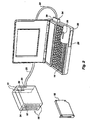
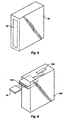
- Figure 1 shows an external docking bay 10.
- a second, identical, external docking bay is also shown in phantom image in figure 1.
- the single external docking bay 10 pictured is designed to enable a single portable computer peripheral 12 to be electrically coupled to a portable computer 14 (see figure 2) or to some other computing device.
- a stand 11, is provided to hold the external docking bay 10.
- the portable computer 14 is a notebook computer manufactured and/or sold by such industry leaders in computer notebooks such as IBM Corporation (“IBM”), Compaq Computer Corporation (“Compaq”) or Toshiba America Information Systems, Inc. ("Toshiba”).
- the external docking bay 10 is comprised of an insertion end, generally designated at 16, and also a bay door 17 where the portable computer peripheral 12 is inserted into the external docking bay 10.
- an interface port diagrammatically represented at 20.
- the portable computer peripheral 12 is electrically coupled to the interface port 20 because the interface port 20 is constructed to be substantially identical in physical dimensions and pinouts to a multi-function port 35 in the multi-function bay 36 of the portable computer 14.
- the interface port 20 is electrically coupled to a cable 22 which is also electrically coupled to a coupling device 24 shown partially inserted into the portable computer 14.
- the coupling device 24 (here configured as a PC card) enables the external docking bay 10 to be electrically coupled to the portable computer 14 at a portable computer interface port 30 (figure 2).
- the external docking bay 10 is constructed to receive portable computer peripherals 12 which are designed to fit within a multi-function bay 36 of the portable computer 14 without modification. Therefore, the pertinent dimensions the external docking bay 10 are the same as those of a multi-function bay 36 in the portable computer 14.
- the two or more external docking bays 10 shown in figure 1 can be joined together as shown by the phantom image of an external docking bay 10 in figure 1 and as shown in figure 2.
- a plurality of portable computer peripherals 12 can therefore be simultaneously coupled to the portable computer 14.
- One of the benefits of this configuration is that instead of having to swap portable computer peripherals 12 by shutting down the computer, replacing the current portable computer peripheral 12 with the desired portable computer peripheral 12, and then rebooting, all portable computer peripherals 12 are available without swapping.
- the system is capable of "hot swapping" of peripherals.
- a management for the use of data communication lines within the cable 22 when two or more external docking bays 10 are coupled together is used.
- a communication management between two or more external docking bays 10, which is similar to bus arbitration techniques can be used, as known to those skilled in the art. Arbitration techniques determine which devices are able to use bus lines and when.
- FIG 2 an illustration of an exemplary situation of the system described in figure 1 will be provided.
- a user has a floppy drive unit 28 presently installed in a multi-function bay 36 of the portable computer 14, this system enables simultaneous use of another portable computer peripheral 12, for example a CD-ROM drive unit 32 which is inserted into the external docking bay 10.
- a CD-ROM drive unit 32 which is inserted into the external docking bay 10.
- the external docking bay 10 is simultaneously coupled via a specific computer interface port.
- a PC card slot 30 is used on the portable computer 14 as the interface between the portable computer 14 and the external docking bay 10.
- PC card (PCMCIA) port 30 is an almost universally available interface standard on portable computers.
- An added benefit of using the PC card slot 30 as the interface for the external docking bay 10 is that the multi-function bay 36 of the portable computer 14 can still be used.
- Two external docking bays 10 are shown coupled together in figure 2 so as to have the ability to simultaneously accept two computer peripherals 12.
- the CD-ROM drive unit 32 is inserted into the external docking bay 10 at the insertion end 16 until it is electrically coupled to an associated interface port 20 within.
- the remaining interface port 20 within external docking bay 10 is shown having a tape drive backup unit 34 installed therein.
- the tape drive backup unit 34 is optional.
- the interface ports 20 within the external docking bay 10 do not have to be filled for proper operation of the portable computer 14.
- One or both of the interface ports 20 can be empty when the portable computer 14 is booted.
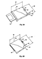
- FIG 2A is a perspective view of a peripheral device, generally designated at 40.
- the peripheral device 40 is a mass storage device which is compliant with the standard promulgated by Iomega and known in the industry as a ZIPTM drive and which receives a disk, designated at 42, known in the industry as a ZIPTM disk.
- the peripheral device 40 is particularly configured to be received into the multi-function bay 36 (see figure 2) of a computer manufactured by Toshiba.
- the peripheral device 40 includes an enclosure or a housing 41.
- the housing 41 has a length 47, a width 45, and a thickness 46 all of which is specific to peripherals which are to be received into the multi-function bay 36 of computers complying with the pertinent standard promulgated by Toshiba.
- the housing 41 includes a lip 48 which extends from one side of the housing 41 and has a thickness 44 which is less than the thickness represented at 46.
- An electrical connector 49 is provided to make electrical connection with a corresponding electrical connector (represented at 35 in figure 2) provided within the multi-function bay 36 of a computer complying with the multi-function bay standard of Toshiba or within the external docking bay 10 (figure 2) complying with the multi-function bay standard of Toshiba.
- FIG 2B is a perspective view of another peripheral device, generally designated at 50.
- the peripheral device 50 is also a mass storage device which is compliant with the standard promulgated by Iomega and known in the industry as a ZIPTM drive which receives a ZIPTM disk.
- the peripheral device 50 is particularly configured to be received into the multi-function bay 36 (see figure 2) which complies with the standard promulgated by IBM.
- the peripheral device 50 includes an enclosure or a housing 57.
- the housing 57 has a length 56, a width 55, and a thickness 54, all of which is specific to peripherals which are to be received into the multi-function bay 36 of computers complying to the standard promulgated by IBM.
- the housing 57 includes a lip 53 which extends from one side of the housing 57 and has a thickness 51 which is less than the thickness represented at 54.
- An electrical connector 58 is provided to make electrical connection with a corresponding electrical connector (represented at 35 in figure 2) provided within the multi-function bay 36 of a computer complying with the multi-function bay standard of IBM or within the external docking bay 10 (figure 2) complying with the multi-function bay standard of IBM.
- Peripheral devices which comply with the multi-function bay standard of any number of different organizations and manufacturers can be arrived at using the teachings set forth herein.
- steps to be carried out are : 1) Providing a housing for the peripheral device which physically fits within the multi-function bay adhering to the pertinent standard; 2) Providing an electrical connector which is compatible with the corresponding electrical connector provided in the pertinent multi-function bay; and, 3) Providing a translation interface so that translation of communications between a first interface standard and a second interface standard can occur so that an operative link between the host computer and the peripheral is established and maintained.
- One skilled in the art can use these steps to arrive at peripheral devices which operate within the multi-function bays adhering to any number of different standards.
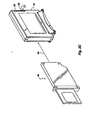
- Figure 2C is a perspective view of the peripheral device 40 represented in figure 2A ready to be inserted into the external peripheral device bay represented in figure 1 as indicated by arrow 60.
- the peripheral device 40 is inserted and removed from the device bay in accordance with the standard promulgated by appropriate manufacturer or organization.
- Figure 2D is an exploded perspective view of one external peripheral device bay 10 represented in figure 1.
- a computing device such as a desktop computer.
- the interface port 20 will change according to the standards promulgated by different manufacturers and different organizations.
- the interface port is a 50 conductor connector having the following pin assignments: Pin Assignment 1-40 ATAPI Interface 41, 42 +5 volts 43-44 GND 47 Audio Right 48 Audio GND 49 Audio Left 50 Audio GND
- FIG. 2D Represented in figure 2D are a first half housing 10A and a second half housing 10B.
- the first half housing 10A and the second half housing 10B are joined together using some of the screws indicated at 15 such that peripheral devices, such as the peripheral device 40 (figure 2A) and the peripheral device 50 (figure 2B) can be received therein.
- peripheral devices such as the peripheral device 40 (figure 2A) and the peripheral device 50 (figure 2B) can be received therein.
- the arrangement illustrated in figure 2d can securely receive and hold a peripheral device and the arrangement illustrated in figure 2D is particularly configured to receive peripherals complying with the standards promulgated by Toshiba.
- a circuit board 13 includes the interface port 20 and a cable connector 21 which receives cable 22.
- a spring 19 is included to make a ground connection with the peripheral device in accordance with the standard promulgated by Toshiba.
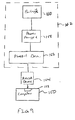
- Figure 3 is a flow chart showing one general method of operation of the system illustrated in figure 1.
- FIG. 3 begins with step 80 where all desired portable computer peripherals 12 are installed in an external docking bay 10 having an appropriate number of bays. It should be mentioned that although it was explained earlier that none or as a few as one of the external docking bays 10 need to be filled for the portable computer 14 to operate, the same is true for the multi-function bay 36 of the portable computer 14. The multi-function bay 36 can be empty and the operation of the portable computer 14 will not be affected.
- Step 82 requires that the portable computer 14 be rebooted.
- the portable computer peripherals 12 are now all simultaneously available to the user.
- the operating system and/or a hardware component such as a bus controller of the portable computer 14 assigns a unique drive designation to each of the portable computer peripherals 12 in step 84 so that they can be accessed accordingly.
- the portable computer peripheral 12 in the multi-function bay could always be assigned the designation "C:”
- the first peripheral in the external docking bay 10 could always be assigned the designation "D:”
- so forth until the last portable computer peripheral 12 in the external docking bay 10 is assigned a drive designation. If there is no portable computer peripheral 12 in the multi-function bay 36, then the first portable computer peripheral 12 in the external docking bay 10 will receive the drive designation "C:" and so on as before.
- Step 86 encompasses the concept of deciding which of the portable computer peripherals 12 the portable computer 14 is going to communicate with, and when. For example, an interrupt-type method of communication is chosen.
- an interrupt can be set which designates the appropriate portable computer peripheral 12 as requiring attention for the portable computer 14.
- Step 88 shows that once the portable computer 14 has determined that one of the portable computer peripherals 14 requires attention, a predetermined amount of time is devoted to responding to the portable computer peripheral's 12 task.
- the predetermined amount of time might require repeated interruptions of the task while other functions of the portable computer 14 are carried out.
- the function described can be executed in many different ways. However, the portable computer 14 and its operating system can be assumed to already possess the ability to control a plurality of portable computer peripherals 12 already. This should be clear in that the functionality added is an extension of the portable computer's 14 ability to share bus time and perform other task for an internal hard drive 38 and floppy drive unit 28 which are already typically installed in the portable computer 14 (see figure 2).
- Line 90 is also included to indicate that the portable computer 14 is always looping back to check on a status of other portable computer peripherals 12, if any, after a task is completed, or even during a task if the portable computer 14 and operating system enable such an interruption. It will be appreciated by those skilled in the art that peripheral device status checking is accomplished by numerous methods.
- the impetus for communication between the portable computer peripherals 12 and the portable computer 14 in step 84 can be replaced with a polling scheme.
- the portable computer 14 will actively poll all portable computer peripherals in a rotating fashion, basically asking each peripheral if it requires communication. If not, the portable computer 14 queries a next portable computer peripheral 12 in an endless loop. The loop is only interrupted when a portable computer peripheral 12 requires attention, and then perhaps only in small segments of time until the portable computer peripheral 12 no longer requires attention from the portable computer 14 when its task is complete.
- FIG 4 shows an additional step 92 which is inserted between the steps 82 and 84.
- the portable computer 14 makes a determination upon bootup about which type of portable computer peripherals 12 are electrically coupled to the external docking bay 10. While the interface port 20 may have the same arrangement of pins for the many different models or computer manufacturers of portable computers 14, the signals on the pins may differ significantly. Therefore, it is possible to determine at an appropriate time what type of computer peripheral 12 the portable computer 14 will be communicating with. The external docking bay 10 can then make the appropriate adjustments to compensate for changes in signal assignments on pins of various portable computer peripherals 12. It is also envisioned that some portable computer peripherals 12 use the same pinout configurations, but that signal timing is altered.
- the system is prepared to compensate for these timing differences or pinout variations by an appropriate method known to those skilled in the art. For example, a signal which must be generated on a particular line for a certain length of time, as required by the portable computer 14, can be extended by the external docking bay 10 if the portable computer peripheral 12 otherwise drops the signal too early. Likewise, the external docking bay 10 can also cut signal short in the same manner.
- FIG. 5 shows that an external hard drive unit 90 is electrically coupled to the external docking bay 10.
- the external docking bay 10 can be used as an interface between the bus of the portable computer 14 and the hard drive 90. It should be appreciated by those skilled in the art that another advantage therefore is the ability to function as an interface to the portable computer 14 for peripherals which are not normally compatible.
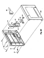
- FIG. 6 illustrates that portable computer peripherals 12 can also be used on a desktop computer 100, and thereby avoid duplicate but otherwise necessary and expensive proprietary purchases to outfit both a portable computer 14 and the desktop computer 100 with the same peripherals. It should be realized that this example has application for use in an expansion chassis (not shown) as well.
- FIG. 6 shows that an internal docking bay 102 is electrically coupled to an internal bus slot 104 of the desktop computer 100 by any appropriate means such as direct connection or via a cable, and shown here in a tower or mini-tower configuration.
- the bus used by the desktop 100 can be any of those commonly used today such as ISA, BISA, Microchannel, VESA, and PCI and which are known to those skilled in the art.
- ATAPI, PCMCIA, parallel, serial, SCSI or FireWire peripheral connections might also be used to couple the internal docking bay 102 to the desktop computer 100.
- the internal docking bay 102 provides an interface between the signals being used by the computer peripheral 12, and the industry standardized bus signals used by the desktop computer 100.
- an internal docking bay 102 would be purchased for using the computer peripherals 12 of only a particular computer manufacturer. All of the computer peripherals 12 would then be able to function on the desktop computer 100 from within the internal docking bay 102. Alternatively, more than one internal docking bay 102 can be included in the desktop computer 100, each internal docking bay 102 adhering to a different interface standard.
- figure 7 eaches the installation of a drive 110 which utilizes an easily portable, high density, removable storage medium.
- a drive and storage medium are the ZIPTM drive as disclosed previously.
- the ZIPTM drive 110 has been constructed such that it is able to fit within the multi-function bay 36.
- the ZIPTM drive 110 can be used in the external docking bay 10 (figure 1) and the internal docking bay 102 (figure 6) of previously described systems.
- FIG 8 It is also possible to accommodate one or more industry standard interfaces.
- a computer device 118 As is known in the industry or which may become available in the future.
- the computing device 118 can include one or more industry standard interfaces such as those known as PCI, PCMCIA, CardBus, IEEE 1284 and/or FireWire (IEEE 1394).
- the hardware and/or software necessary to implement these industry standards is represented by the interface 120 in figure 8.
- the signals which are conveyed by the interface 120 are communicated by a link 116 which may be a hardwired link or a wireless link, in accordance with which the industry standard interface 120 adheres.
- Wireless links within the scope of the present invention can be those which adhere to an industry standard infrared communication protocol or to a proprietary infrared communication protocol.
- wireless links which adhere to an industry standard radio frequency protocol or to a proprietary radio frequency communication protocol can also be used.
- an adaptable docking bay 114 which preferably substantially includes the features and structures described in connection with docking bay 10 described earlier.
- the adaptable docking bay 114 also includes an adaptable interface which can accommodate any one or more than one industry standard interface such as ISA, PCI, PCMCIA, CardBus, and/or FireWire so that reliable and efficient communication between the adaptable docking bay 114 and the computing device 118 can occur. More information on the FireWire standard can be obtained from the IEEE 1394 standard.
- the docking bay 10 receives one of a number of different peripherals.
- a peripheral 124 is received into the adaptable docking bay 114.
- the peripheral 124 may be any number of different types of devices, such CD-ROM drives, disk drives, and many other different types of devices. Such devices may require different industry standard interface. Thus; the peripheral 124 may require an interface such as an IDE interface, an ATAPI interface, FireWire interface, SCSI interface, or another interface.
- the interface adapter 122 includes the hardware and/or software which is necessary to allow data and instructions to be transferred between two dissimilar standards.
- the interface adapter 122 allows communication to efficiently occur between one or more of the following standards, all of which are well known in the industry: PCCard, PCI, Parallel, IEEE 488, Serial, RS-232, PS/2, PCMCIA, CardBus, FireWire, IDE, ATAPI, or some proprietary interface which one or more particular manufacturers have adopted or may adopt in the future.
- the interface adaptor 122 can preferably provide adaptable communication in accordance with the FireWire interface, if that is the standard with which the computing device 118 is equipped. It is to be understood that many different types of computing device can be used, not just the computing device 118 represented in figure 8.
- figure 9 is a block diagram.
- many computing peripherals have not been designed considering portability.
- Many computing peripherals are designed to operate assuming that a high current source is available to operate the peripheral.
- the present invention advantageously provides a system for providing power to peripherals which provides advantages not previously available.
- Figure 9 provides a block diagram including a computer indicated at 150.
- the computer 150 can be any device which stores, manipulates, or utilizes data, for example, portable computers, desktop computers, personal digital assistants (PDAs), still digital cameras, video cameras, and so forth.
- the computer 150 includes a PC card slot 152 which is compliant with the pertinent PCMCIA standard, as is well known in the industry.
- a PCMCIA device 154 is inserted into the PC card slot 152 to provide an interface between the computer 150 and a peripheral device 156 so that operation and communication can occur therebetween.
- the PCMCIA standard requires that five volts be provided at the PC card slot 152 and the standard requires that only 800 milliamps be provided.
- the PCMCIA device preferably provides an interface between the standard used by the peripheral device 156 (for example the ATAPI standard) and the standard used by the computer 150 (for example the PCMCIA standard).
- the PCMCIA device 154 passes through the five volts to the peripheral device 156.
- a power management unit 158 is provided in accordance with the present invention.
- the power management unit 158 can be housed in the same enclosure, represented by the dashed line 162, as the peripheral device 156, or can be separately housed. Also represented in figure 9 is a battery 160.
- the battery 160 can be any power storage device and is preferably a rechargeable electrochemical cell.
- the battery 160 can comprise one or more nickel-cadmium cells, one or more nickel-metal-hydride cells, or one or more lithium-ion cells.
- the battery 160 is also preferably housed within the enclosure 162.
- the enclosure 162 can preferably be the housing of the external docking bay 10 (figure 1) or the housing of the ZIPTM drive 110 which fits within the multi-function bay 36 (figure 7).
- the battery 160 and/or the power management unit 158 can be located outside of the enclosure 162.
- the power management unit 158 monitors the current which is drawn by the peripheral device 156 from the PC card slot 152 through the PCMCIA device 154. As the current drawn by the peripheral device 156 nears and exceeds a predetermined threshold, the power management unit 158 draws current from the battery 160 to supplement the current drawn from the PC card slot 152 so the peripheral device 156 will have adequate current for proper operation. It is also within the scope of the present invention for the power management unit to recharge the battery 160 when the current drawn by the peripheral device 156 falls below the predetermined threshold.
- the battery 160 can also preferably be charged via an external source, such as a power supply connected to an AC current supply (not represented in the figures).
- the predetermined threshold is preferably in the range from about 500 mA to about 800 mA, more preferably about 600 mA to about 700 mA, and most preferably is 650 mA. It will be appreciated that the predetermined threshold can be different than that specified herein and still fall within the scope of the present invention. It will be appreciated that the present invention provides advantages not heretofore available in the art.
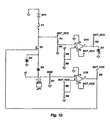
- figure 10 is a detailed schematic diagram showing one preferred arrangement for implementing the power management feature represented in figure 9. It is to be appreciated that the detailed schematic diagram of figure 10 is not to be considered limiting of the scope of the present invention but is to be considered merely exemplary of the many different embodiments which can incorporate the present invention.
- the components represented in figure 10 correspond to those components which carry out the functions of the battery (160 in figure 9) and the power management unit (158 in figure 9). For purposes of clarity, the reference designations which are customarily included in detailed schematic diagrams have been retained. Table A, below, provides a description of the preferred components represented in Figure 10.
- the circuit represented therein is just one example of a means for detecting when the current drawn by the peripheral device exceeds a predetermined threshold and for supplying supplementary current to the peripheral device. It is to be understood that many different structures can carry out the functions of detecting when the current drawn by the peripheral device exceeds a predetermined threshold and for supplying supplementary current to the peripheral device and all such structures and arrangements which perform the same or equivalent functions are to be considered within the scope of the means for detecting when the current drawn by the peripheral device exceeds a predetermined threshold and for supplying supplementary current to the peripheral device.
- the power management aspect of the present invention has utility with many different types of peripheral devices, both those which are presently available and which will become available in the future.
- An example of a peripheral device which will shortly become available is the n•hand disk drive which has been announced by Iomega which will use magnetic disks which are smaller than ZIPTM disks (current specification 2 inches by 2 inches) and which are expected to hold 20 MB of data and which are suited for applications which currently require flash memory cards.
- the n•hand device is particularly suited for inclusion in apparatus such as Personal Digital Assistants (PDAs) and other miniature digital electronic devices.
- PDAs Personal Digital Assistants
- Devices such as PDAs are often designed to consume very little power in order to maximize battery life while using small battery cells. Thus, such devices may only be able to provide as little as, for example, 200 mA, 100 mA, or 50 mA to a peripheral device.
- Devices such as PDAs may comply with the PCMCIA interface standard except for being unable to provide the current which is otherwise expected under the PCMCIA interface standard.
- Those skilled in the art will readily be able to modify the structures disclosed herein, and to arrive at new structures using the teachings presented herein, to provide power management for peripheral devices which could not otherwise be reliably and conveniently used with low power digital electronic apparatus.
- the capacity of the battery (or other power storage component) shown in figure 10 may be altered as well as altering the threshold at which supplementary current provided to the peripheral and how much current is provided to the peripheral.
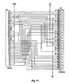
- Figure 11 is a detailed schematic diagram showing one preferred arrangement for adapting a peripheral device to the PCMCIA standard.
- the components represented in figure 11 carry out the functions of the coupling device 24 represented in figure 2 and the components represented in figure 11 can most preferably be housed within a PC card format.
- the schematic diagram of figure 11 is only one example of a means for translating communications between a computer in accordance with the first interface standard and the peripheral device in compliance with the second interface standard such that an operative link between the computer and the peripheral device is established when a computer peripheral is nested in the peripheral bay. It is to be understood that many different structures can carry out the functions of means for translating communications between a computing device in accordance with the first interface standard and the peripheral device in compliance with the second interface standard and all such structures and arrangements which perform the same or equivalent functions are to be considered within the scope of the means for translating communications between a computer in accordance with the first interface standard and the peripheral device in compliance with the second interface standard.
- the arrangement represented in the detailed schematic diagram of figure 11 is most preferred for translating between the well known ATAPI interface standard and the PCMCIA interface standard. As can be appreciated from an examination of the detailed schematic diagram of figure 11, the arrangement represented in figure 11 does not require any active components to provide the desired translation. It is also possible to provide means for translating communications which includes active components which can modify existing signals, and create new signals, which are necessary to translate between interface standards. For example, those skilled in the art can arrive at means for translating communications between any of following interface standards: PCCard, PCI, Parallel, IEEE 488, Serial, RS-232, PS/2, PCMCIA, CardBus, FireWire, IDE, ATAPI interfaces; using the teachings provided herein.
Landscapes
- Engineering & Computer Science (AREA)
- Theoretical Computer Science (AREA)
- General Engineering & Computer Science (AREA)
- Computer Hardware Design (AREA)
- Physics & Mathematics (AREA)
- General Physics & Mathematics (AREA)
- Human Computer Interaction (AREA)
- Power Sources (AREA)
- Hardware Redundancy (AREA)
- Bus Control (AREA)
Abstract
Description
| Pin | Assignment |
| 1-40 | |
| 41, 42 | +5 volts |
| 43-44 | |
| 47 | |
| 48 | |
| 49 | |
| 50 | Audio GND |
| Figure 10 | |
| Reference Designation | Description |
| BT1 | Nickel-Cadmium Battery |
| F1 | Fuse |
| R1 | 470K |
| R3 | 100K |
| U1A | LM393 |
| R2 | 4.7K |
| D1 | LED |
| R4 | 400K |
| R5 | 100K |
| D2 | 1N5235A |
| Q1 | MTP12P10 |
| JP1 | Power connector to peripheral device |
| R7 | .1 |
| R8 | 82.5K |
| R9 | 1K |
| U1B | LM393 |
| R6 | 4.7K |
Claims (20)
- A system for providing power to a digital peripheral device when a primary power supply provides insufficient power, the system comprising:characterized in thatmeans (10) for removably housing the peripheral device, the peripheral device (12) including at least a first electrical connector for communicating at least a first electrical signal;means (24) for coupling the first electrical signal between the peripheral device and a computing device, the computing device including a primary power supply;means for conveying electrical power from the primary power supply to the peripheral device;means (160) for storing electrical power,positioned outside of the computing device;
said system further comprises a power management circuit means (158) being capable of detecting when the current drawn by the peripheral device exceeds a predetermined threshold and, responsive thereto, being capable of supplying supplementary power to the peripheral device when the current drawn by the peripheral device exceeds the predetermined threshold such that the operation of the peripheral device is maintained;
said circuit means being adapted to provide supplementary power by supplying additional current to the peripheral device from the means for storing electrical power in order to supplement the current provided by the primary power supply. - A system as defined in claim 1, characterized in that
the means (10) for removably housing the peripheral device (12) comprises either an internal or external docking bay. - A system as defined in claim 1 or 2, characterized in that
the computing device (14, 150) comprises one of the following devices:a desktop computer, a notebook computer, a palmtop computer, a personal digital assistant, a digital camera;the peripheral device (12) comprises either a magnetic storage device or an optical storage device. - A system as defined in one of claims 1-3, characterized in that
the means for coupling the first electrical signal between the peripheral device and the computing device comprises a cable (22). - A system as defined in one of claims 1-4, characterized in that
the power supply provides 5 volts DC. - A system as defined in one of claims 1-5, characterized in that
the means for conveying electrical power from the primary power supply to the peripheral device (12) comprises a cable (22). - A system as defined in one of claims 1-6, characterized in that
the system comprises an enclosure (122) within which the peripheral device is housed;
the means for storing electrical power comprises a rechargeable battery positioned within the enclosure. - A system as defined in one of the claims 1-6, characterized in that
the system comprises an enclosure within which the peripheral device is housed;
the means for storing electrical power comprises a rechargeable battery positioned outside of the enclosure. - A system as defined in one of claims 1-8, characterized in that
the means (158) for detecting when the current drawn by the peripheral device (12) exceeds a predetermined threshold comprises means for detecting when the current drawn by the peripheral device exceeds a current value in the range from about 600 mA to about 700 mA. - A system as defined in one of claims 1-8, characterized in that
the means (158) for detecting when the current drawn by the peripheral device (12) exceeds a predetermined threshold comprises means for detecting when the current drawn by the peripheral device exceeds a current value in the range from about 50 mA to about 200 mA. - A system as defined in one of claims 1-8, characterized in that
the means (158) for detecting when the current drawn by the peripheral device (12) exceeds a predetermined threshold comprises means for detecting when the current drawn by the peripheral device exceeds a current value equal to about 650 mA. - A system as defined in one of claims 1-11, characterized in that
the power management circuit means (158) for detecting when the current drawn by the peripheral device (12) exceeds a predetermined threshold and for supplying supplementary power to the peripheral device comprises:a first operational amplifier (U1B) having an input connected to a first power input (1) of the peripheral device (12) for sensing the current drawn by the peripheral device; anda switching device (Q1) in series with the means for storing electrical power (BT1) and connected to a second power input of the peripheral device (2). - A system as defined in one of claims 1-12, characterized in that
the first electrical connector comprises a forty conductor connector. - A system as defined in one of claims 1-13, characterized in that
the system comprises means for translating communications between the computing device (12) in accordance with a first interface standard and the peripheral device in compliance with a second interface standard such that an operative link between the computing device and the peripheral device is established when the peripheral device is nested in a first peripheral bay. - The system as defined in one of claims 1-14, characterized in that
the means (10) for removably housing the peripheral device is positioned externally to the computing device. - The system as defined in claim 14, characterized in that
the first peripheral bay is positioned internally in the computing device. - The system as defined in one of claims 1-16, characterized in that
the means for making physical and electrical connection with the peripheral device comprises a fifty conductor connector and a cable. - The system as defined in one of claims 1-17, characterized in that
the peripheral device comprises an enclosure having first, second, third and fourth sides, the enclosure having a substantially rectangular shape having a lip extending from the first side thereof. - The system as defined in claim 14, characterized in that
the first interface standard is the PCMCIA interface standard. - The system as defined in claim 14, characterized in that
the second interface standard is ATAPI interface standard.
Applications Claiming Priority (5)
| Application Number | Priority Date | Filing Date | Title |
|---|---|---|---|
| US743515 | 1985-06-11 | ||
| US74351596A | 1996-11-04 | 1996-11-04 | |
| US800397 | 1997-02-14 | ||
| US08/800,397 US5941963A (en) | 1997-02-14 | 1997-02-14 | System and method for interconnection of computer peripherals via multiple interfaces |
| PCT/US1997/020026 WO1998020404A2 (en) | 1996-11-04 | 1997-11-04 | System and method for adapting computer peripherals |
Publications (3)
| Publication Number | Publication Date |
|---|---|
| EP1012692A2 EP1012692A2 (en) | 2000-06-28 |
| EP1012692A4 EP1012692A4 (en) | 2001-08-01 |
| EP1012692B1 true EP1012692B1 (en) | 2004-06-23 |
Family
ID=27114165
Family Applications (1)
| Application Number | Title | Priority Date | Filing Date |
|---|---|---|---|
| EP97947336A Expired - Lifetime EP1012692B1 (en) | 1996-11-04 | 1997-11-04 | System for power supply of computer peripherals |
Country Status (7)
| Country | Link |
|---|---|
| EP (1) | EP1012692B1 (en) |
| JP (5) | JP2001506780A (en) |
| AT (1) | ATE269985T1 (en) |
| AU (1) | AU5244398A (en) |
| CA (1) | CA2270538A1 (en) |
| DE (1) | DE69729664T2 (en) |
| WO (1) | WO1998020404A2 (en) |
Cited By (1)
| Publication number | Priority date | Publication date | Assignee | Title |
|---|---|---|---|---|
| CN101923527A (en) * | 2009-03-03 | 2010-12-22 | 仁宝电脑工业股份有限公司 | Integrated network chip and electronic apparatus |
Families Citing this family (3)
| Publication number | Priority date | Publication date | Assignee | Title |
|---|---|---|---|---|
| US5941963A (en) * | 1997-02-14 | 1999-08-24 | Paul Charles | System and method for interconnection of computer peripherals via multiple interfaces |
| JP2002099361A (en) * | 2000-09-25 | 2002-04-05 | F & F:Kk | Peripheral device |
| JP6703292B1 (en) * | 2019-09-05 | 2020-06-03 | 富士通クライアントコンピューティング株式会社 | Electronics |
Family Cites Families (32)
| Publication number | Priority date | Publication date | Assignee | Title |
|---|---|---|---|---|
| JPS63102087A (en) * | 1986-10-17 | 1988-05-06 | Nec Corp | Cartridge type floppy disk drive |
| JP2634603B2 (en) * | 1987-09-10 | 1997-07-30 | 株式会社リコー | Card usage system |
| JPH031428A (en) * | 1989-05-29 | 1991-01-08 | Hitachi Ltd | Ion beam apparatus |
| JPH0449589A (en) * | 1990-06-19 | 1992-02-18 | Nec Corp | Ac adapter for power supply |
| JP2829098B2 (en) * | 1990-06-25 | 1998-11-25 | 株式会社東芝 | Computer system |
| US5313642A (en) * | 1990-10-03 | 1994-05-17 | Seagull Scientific Systems, Inc. | Power interface for peripheral devices |
| JPH04155417A (en) * | 1990-10-19 | 1992-05-28 | Toshiba Corp | Device for extending function |
| JPH04205343A (en) * | 1990-11-30 | 1992-07-27 | Toshiba Corp | Information processor |
| JP3163680B2 (en) * | 1991-09-04 | 2001-05-08 | ヤマハ株式会社 | Power supply |
| JPH0567028A (en) * | 1991-09-06 | 1993-03-19 | Toshiba Corp | Information processor |
| JPH05100862A (en) * | 1991-10-04 | 1993-04-23 | Casio Comput Co Ltd | Data processor |
| JPH05100990A (en) * | 1991-10-09 | 1993-04-23 | Seiko Epson Corp | Information processor |
| JPH05173949A (en) * | 1991-12-25 | 1993-07-13 | Nec Corp | Microprocessor device |
| JPH05260232A (en) * | 1992-03-13 | 1993-10-08 | Ricoh Co Ltd | Image forming device with uninterruptive power supply |
| JP3155613B2 (en) * | 1992-06-12 | 2001-04-16 | キヤノン株式会社 | Copier |
| US5402518A (en) * | 1992-07-22 | 1995-03-28 | Pcvoice, Inc. | Sound storage and sound retrieval system having peripheral with hand operable switches |
| US5311397A (en) * | 1992-08-06 | 1994-05-10 | Logistics Management Inc. | Computer with modules readily replaceable by unskilled personnel |
| US5579487A (en) * | 1992-10-02 | 1996-11-26 | Teletransaction, Inc. | Portable work slate computer with multiple docking positions for interchangeably receiving removable modules |
| JPH06131083A (en) * | 1992-10-15 | 1994-05-13 | Mita Ind Co Ltd | Interface switching device |
| JPH06149728A (en) * | 1992-11-16 | 1994-05-31 | Hitachi Ltd | I/o bus extension device and its control method |
| NL194144C (en) * | 1993-09-15 | 2001-07-03 | Ericsson Inc | Power supply system for a plug-in module. |
| JPH07141114A (en) * | 1993-11-16 | 1995-06-02 | Canon Inc | Adaptor for memory card |
| JP3306639B2 (en) * | 1994-04-06 | 2002-07-24 | 株式会社ワイ・イー・データ | Peripheral equipment |
| US5537599A (en) * | 1994-04-25 | 1996-07-16 | Rohm Co., Ltd. | CPU controlled apparatus formed on an IC |
| JPH0816512A (en) * | 1994-06-29 | 1996-01-19 | Sony Corp | Communication interface |
| US5659761A (en) * | 1994-10-18 | 1997-08-19 | Hand Held Products | Data recognition apparatus and portable data reader having power management system |
| US5590336A (en) * | 1994-10-25 | 1996-12-31 | Microsoft Corporation | Method and apparatus for performing overlapping service of multiple IDE peripheral devices |
| JP3011657U (en) * | 1994-11-29 | 1995-05-30 | 船井電機株式会社 | Electronic device with electronic camera |
| JPH08190760A (en) * | 1995-01-09 | 1996-07-23 | Matsushita Electric Ind Co Ltd | Auto-changer of disk cartridge |
| JPH08278835A (en) * | 1995-04-05 | 1996-10-22 | Hitachi Ltd | Card battery and portable electronic equipment using the same |
| US5668654A (en) * | 1995-05-30 | 1997-09-16 | The Whitaker Corporation | Package for an infrared communications adapter |
| EP0814399A1 (en) * | 1996-06-21 | 1997-12-29 | Archos | Device and process for powering an external information carrier reader connected to a computer, and external reader including this device |
-
1997
- 1997-11-04 EP EP97947336A patent/EP1012692B1/en not_active Expired - Lifetime
- 1997-11-04 JP JP52167798A patent/JP2001506780A/en not_active Ceased
- 1997-11-04 AT AT97947336T patent/ATE269985T1/en not_active IP Right Cessation
- 1997-11-04 CA CA002270538A patent/CA2270538A1/en not_active Abandoned
- 1997-11-04 DE DE69729664T patent/DE69729664T2/en not_active Expired - Lifetime
- 1997-11-04 AU AU52443/98A patent/AU5244398A/en not_active Abandoned
- 1997-11-04 WO PCT/US1997/020026 patent/WO1998020404A2/en active IP Right Grant
-
2008
- 2008-12-10 JP JP2008314710A patent/JP2009104625A/en active Pending
-
2010
- 2010-03-08 JP JP2010050409A patent/JP5047319B2/en not_active Expired - Fee Related
-
2011
- 2011-09-16 JP JP2011203820A patent/JP5144796B2/en active Active
- 2011-11-25 JP JP2011256995A patent/JP5215449B2/en active Active
Cited By (2)
| Publication number | Priority date | Publication date | Assignee | Title |
|---|---|---|---|---|
| CN101923527A (en) * | 2009-03-03 | 2010-12-22 | 仁宝电脑工业股份有限公司 | Integrated network chip and electronic apparatus |
| CN101923527B (en) * | 2009-03-03 | 2012-09-12 | 仁宝电脑工业股份有限公司 | Integrated network chip and electronic apparatus |
Also Published As
| Publication number | Publication date |
|---|---|
| CA2270538A1 (en) | 1998-05-14 |
| DE69729664T2 (en) | 2004-11-11 |
| AU5244398A (en) | 1998-05-29 |
| JP5144796B2 (en) | 2013-02-13 |
| WO1998020404A2 (en) | 1998-05-14 |
| JP2012014727A (en) | 2012-01-19 |
| EP1012692A2 (en) | 2000-06-28 |
| JP5047319B2 (en) | 2012-10-10 |
| JP2012094160A (en) | 2012-05-17 |
| JP2010140509A (en) | 2010-06-24 |
| JP2009104625A (en) | 2009-05-14 |
| EP1012692A4 (en) | 2001-08-01 |
| JP2001506780A (en) | 2001-05-22 |
| JP5215449B2 (en) | 2013-06-19 |
| DE69729664D1 (en) | 2004-07-29 |
| WO1998020404A3 (en) | 1998-10-01 |
| ATE269985T1 (en) | 2004-07-15 |
Similar Documents
| Publication | Publication Date | Title |
|---|---|---|
| US6526515B1 (en) | Remote pluggable system having bays for attachment of computer peripherals | |
| US5854904A (en) | Object-oriented modular electronic component system | |
| US5497464A (en) | Address mapping logic for transferring data between a peripheral device of a base function expander unit and a palmtop computer as if the peripheral was a peripheral of the computer | |
| US5941963A (en) | System and method for interconnection of computer peripherals via multiple interfaces | |
| EP0731940B1 (en) | Modular portable computer | |
| US6900980B2 (en) | Synchronization cradle with expansion card slots | |
| US9158336B2 (en) | Cases for tablet computers and methods | |
| EP0648404B1 (en) | Modular notebook computer | |
| US7035097B2 (en) | 3.5 inch hot-swappable docking module | |
| US20080268331A1 (en) | Battery-backed computer system with externally replaceable battery module | |
| CN110632980A (en) | Intelligent platform | |
| US6898076B2 (en) | Modular information processing system | |
| JP2000089862A (en) | Function expanding device, electronic unit and electronic unit system | |
| CN101313265A (en) | Discrete computer processor system and peripherals system | |
| JP5215449B2 (en) | Apparatus and method for adapting computer peripherals | |
| US6078112A (en) | Computer bay modular adapter | |
| US6078109A (en) | Power supply system for an electric/electronic apparatus | |
| US6772249B1 (en) | Handheld option pack interface | |
| US20090037632A1 (en) | Rechargeable wireless portable device | |
| JP3403121B2 (en) | Battery built-in card adapter and charging device with adapter function | |
| US20050114553A1 (en) | Handheld option pack interface | |
| KR100433430B1 (en) | Portable mobile communication system having adaptor for PCMCIA | |
| WO2001037105A1 (en) | Device bay system with surprise removal prevention for supporting and controlling usb and ieee 1394 peripheral devices | |
| AU648309B2 (en) | Apparatus and method for assembly of direct access storage device with a personal computer | |
| JP2003228447A (en) | Apparatus accommodating device and data processing system |
Legal Events
| Date | Code | Title | Description |
|---|---|---|---|
| PUAI | Public reference made under article 153(3) epc to a published international application that has entered the european phase |
Free format text: ORIGINAL CODE: 0009012 |
|
| 17P | Request for examination filed |
Effective date: 19990504 |
|
| AK | Designated contracting states |
Kind code of ref document: A2 Designated state(s): AT BE CH DE DK ES FI FR GB GR IE IT LI LU MC NL PT SE |
|
| A4 | Supplementary search report drawn up and despatched |
Effective date: 20010619 |
|
| AK | Designated contracting states |
Kind code of ref document: A4 Designated state(s): AT BE CH DE DK ES FI FR GB GR IE IT LI LU MC NL PT SE |
|
| RAP1 | Party data changed (applicant data changed or rights of an application transferred) |
Owner name: MOBILITY ELECTRONICS, INC. |
|
| 17Q | First examination report despatched |
Effective date: 20020507 |
|
| GRAP | Despatch of communication of intention to grant a patent |
Free format text: ORIGINAL CODE: EPIDOSNIGR1 |
|
| RTI1 | Title (correction) |
Free format text: SYSTEM FOR POWER SUPPLY OF COMPUTER PERIPHERALS |
|
| GRAS | Grant fee paid |
Free format text: ORIGINAL CODE: EPIDOSNIGR3 |
|
| GRAA | (expected) grant |
Free format text: ORIGINAL CODE: 0009210 |
|
| AK | Designated contracting states |
Kind code of ref document: B1 Designated state(s): AT BE CH DE DK ES FI FR GB GR IE IT LI LU MC NL PT SE |
|
| PG25 | Lapsed in a contracting state [announced via postgrant information from national office to epo] |
Ref country code: LI Free format text: LAPSE BECAUSE OF FAILURE TO SUBMIT A TRANSLATION OF THE DESCRIPTION OR TO PAY THE FEE WITHIN THE PRESCRIBED TIME-LIMIT Effective date: 20040623 Ref country code: FI Free format text: LAPSE BECAUSE OF FAILURE TO SUBMIT A TRANSLATION OF THE DESCRIPTION OR TO PAY THE FEE WITHIN THE PRESCRIBED TIME-LIMIT Effective date: 20040623 Ref country code: CH Free format text: LAPSE BECAUSE OF FAILURE TO SUBMIT A TRANSLATION OF THE DESCRIPTION OR TO PAY THE FEE WITHIN THE PRESCRIBED TIME-LIMIT Effective date: 20040623 Ref country code: BE Free format text: LAPSE BECAUSE OF FAILURE TO SUBMIT A TRANSLATION OF THE DESCRIPTION OR TO PAY THE FEE WITHIN THE PRESCRIBED TIME-LIMIT Effective date: 20040623 Ref country code: AT Free format text: LAPSE BECAUSE OF FAILURE TO SUBMIT A TRANSLATION OF THE DESCRIPTION OR TO PAY THE FEE WITHIN THE PRESCRIBED TIME-LIMIT Effective date: 20040623 |
|
| REG | Reference to a national code |
Ref country code: GB Ref legal event code: FG4D |
|
| REG | Reference to a national code |
Ref country code: CH Ref legal event code: EP |
|
| REG | Reference to a national code |
Ref country code: IE Ref legal event code: FG4D |
|
| REF | Corresponds to: |
Ref document number: 69729664 Country of ref document: DE Date of ref document: 20040729 Kind code of ref document: P |
|
| PG25 | Lapsed in a contracting state [announced via postgrant information from national office to epo] |
Ref country code: SE Free format text: LAPSE BECAUSE OF FAILURE TO SUBMIT A TRANSLATION OF THE DESCRIPTION OR TO PAY THE FEE WITHIN THE PRESCRIBED TIME-LIMIT Effective date: 20040923 Ref country code: GR Free format text: LAPSE BECAUSE OF FAILURE TO SUBMIT A TRANSLATION OF THE DESCRIPTION OR TO PAY THE FEE WITHIN THE PRESCRIBED TIME-LIMIT Effective date: 20040923 Ref country code: DK Free format text: LAPSE BECAUSE OF FAILURE TO SUBMIT A TRANSLATION OF THE DESCRIPTION OR TO PAY THE FEE WITHIN THE PRESCRIBED TIME-LIMIT Effective date: 20040923 |
|
| PG25 | Lapsed in a contracting state [announced via postgrant information from national office to epo] |
Ref country code: ES Free format text: LAPSE BECAUSE OF FAILURE TO SUBMIT A TRANSLATION OF THE DESCRIPTION OR TO PAY THE FEE WITHIN THE PRESCRIBED TIME-LIMIT Effective date: 20041004 |
|
| PG25 | Lapsed in a contracting state [announced via postgrant information from national office to epo] |
Ref country code: LU Free format text: LAPSE BECAUSE OF NON-PAYMENT OF DUE FEES Effective date: 20041104 Ref country code: IE Free format text: LAPSE BECAUSE OF NON-PAYMENT OF DUE FEES Effective date: 20041104 |
|
| PG25 | Lapsed in a contracting state [announced via postgrant information from national office to epo] |
Ref country code: MC Free format text: LAPSE BECAUSE OF NON-PAYMENT OF DUE FEES Effective date: 20041130 |
|
| REG | Reference to a national code |
Ref country code: CH Ref legal event code: PL |
|
| ET | Fr: translation filed | ||
| PLBE | No opposition filed within time limit |
Free format text: ORIGINAL CODE: 0009261 |
|
| STAA | Information on the status of an ep patent application or granted ep patent |
Free format text: STATUS: NO OPPOSITION FILED WITHIN TIME LIMIT |
|
| 26N | No opposition filed |
Effective date: 20050324 |
|
| REG | Reference to a national code |
Ref country code: IE Ref legal event code: MM4A |
|
| PGFP | Annual fee paid to national office [announced via postgrant information from national office to epo] |
Ref country code: NL Payment date: 20051106 Year of fee payment: 9 |
|
| PGFP | Annual fee paid to national office [announced via postgrant information from national office to epo] |
Ref country code: IT Payment date: 20061130 Year of fee payment: 10 |
|
| PG25 | Lapsed in a contracting state [announced via postgrant information from national office to epo] |
Ref country code: NL Free format text: LAPSE BECAUSE OF NON-PAYMENT OF DUE FEES Effective date: 20070601 |
|
| NLV4 | Nl: lapsed or anulled due to non-payment of the annual fee |
Effective date: 20070601 |
|
| PG25 | Lapsed in a contracting state [announced via postgrant information from national office to epo] |
Ref country code: PT Free format text: LAPSE BECAUSE OF NON-PAYMENT OF DUE FEES Effective date: 20041123 |
|
| REG | Reference to a national code |
Ref country code: GB Ref legal event code: 732E Free format text: REGISTERED BETWEEN 20090625 AND 20090701 |
|
| PG25 | Lapsed in a contracting state [announced via postgrant information from national office to epo] |
Ref country code: IT Free format text: LAPSE BECAUSE OF NON-PAYMENT OF DUE FEES Effective date: 20071104 |
|
| REG | Reference to a national code |
Ref country code: FR Ref legal event code: TP Ref country code: FR Ref legal event code: CA |
|
| REG | Reference to a national code |
Ref country code: FR Ref legal event code: PLFP Year of fee payment: 19 |
|
| REG | Reference to a national code |
Ref country code: FR Ref legal event code: PLFP Year of fee payment: 20 |
|
| PGFP | Annual fee paid to national office [announced via postgrant information from national office to epo] |
Ref country code: FR Payment date: 20161017 Year of fee payment: 20 Ref country code: GB Payment date: 20161026 Year of fee payment: 20 Ref country code: DE Payment date: 20161130 Year of fee payment: 20 |
|
| REG | Reference to a national code |
Ref country code: DE Ref legal event code: R071 Ref document number: 69729664 Country of ref document: DE |
|
| REG | Reference to a national code |
Ref country code: GB Ref legal event code: PE20 Expiry date: 20171103 |
|
| PG25 | Lapsed in a contracting state [announced via postgrant information from national office to epo] |
Ref country code: GB Free format text: LAPSE BECAUSE OF EXPIRATION OF PROTECTION Effective date: 20171103 |