EP0985902A1 - Interferometric device for picking up optical subsurface reflexion and/or transmission characteristics of an object - Google Patents
Interferometric device for picking up optical subsurface reflexion and/or transmission characteristics of an object Download PDFInfo
- Publication number
- EP0985902A1 EP0985902A1 EP99402227A EP99402227A EP0985902A1 EP 0985902 A1 EP0985902 A1 EP 0985902A1 EP 99402227 A EP99402227 A EP 99402227A EP 99402227 A EP99402227 A EP 99402227A EP 0985902 A1 EP0985902 A1 EP 0985902A1
- Authority
- EP
- European Patent Office
- Prior art keywords
- interferometric device
- photosensor
- source
- lenses
- xmzn
- Prior art date
- Legal status (The legal status is an assumption and is not a legal conclusion. Google has not performed a legal analysis and makes no representation as to the accuracy of the status listed.)
- Granted
Links
Images


Classifications
-
- G—PHYSICS
- G01—MEASURING; TESTING
- G01B—MEASURING LENGTH, THICKNESS OR SIMILAR LINEAR DIMENSIONS; MEASURING ANGLES; MEASURING AREAS; MEASURING IRREGULARITIES OF SURFACES OR CONTOURS
- G01B9/00—Measuring instruments characterised by the use of optical techniques
- G01B9/02—Interferometers
- G01B9/02015—Interferometers characterised by the beam path configuration
- G01B9/02027—Two or more interferometric channels or interferometers
- G01B9/02028—Two or more reference or object arms in one interferometer
-
- G—PHYSICS
- G01—MEASURING; TESTING
- G01B—MEASURING LENGTH, THICKNESS OR SIMILAR LINEAR DIMENSIONS; MEASURING ANGLES; MEASURING AREAS; MEASURING IRREGULARITIES OF SURFACES OR CONTOURS
- G01B11/00—Measuring arrangements characterised by the use of optical techniques
- G01B11/02—Measuring arrangements characterised by the use of optical techniques for measuring length, width or thickness
- G01B11/026—Measuring arrangements characterised by the use of optical techniques for measuring length, width or thickness by measuring distance between sensor and object
-
- G—PHYSICS
- G01—MEASURING; TESTING
- G01B—MEASURING LENGTH, THICKNESS OR SIMILAR LINEAR DIMENSIONS; MEASURING ANGLES; MEASURING AREAS; MEASURING IRREGULARITIES OF SURFACES OR CONTOURS
- G01B11/00—Measuring arrangements characterised by the use of optical techniques
- G01B11/22—Measuring arrangements characterised by the use of optical techniques for measuring depth
-
- G—PHYSICS
- G01—MEASURING; TESTING
- G01B—MEASURING LENGTH, THICKNESS OR SIMILAR LINEAR DIMENSIONS; MEASURING ANGLES; MEASURING AREAS; MEASURING IRREGULARITIES OF SURFACES OR CONTOURS
- G01B11/00—Measuring arrangements characterised by the use of optical techniques
- G01B11/24—Measuring arrangements characterised by the use of optical techniques for measuring contours or curvatures
- G01B11/2441—Measuring arrangements characterised by the use of optical techniques for measuring contours or curvatures using interferometry
-
- G—PHYSICS
- G01—MEASURING; TESTING
- G01B—MEASURING LENGTH, THICKNESS OR SIMILAR LINEAR DIMENSIONS; MEASURING ANGLES; MEASURING AREAS; MEASURING IRREGULARITIES OF SURFACES OR CONTOURS
- G01B9/00—Measuring instruments characterised by the use of optical techniques
- G01B9/02—Interferometers
- G01B9/02001—Interferometers characterised by controlling or generating intrinsic radiation properties
- G01B9/0201—Interferometers characterised by controlling or generating intrinsic radiation properties using temporal phase variation
-
- G—PHYSICS
- G01—MEASURING; TESTING
- G01B—MEASURING LENGTH, THICKNESS OR SIMILAR LINEAR DIMENSIONS; MEASURING ANGLES; MEASURING AREAS; MEASURING IRREGULARITIES OF SURFACES OR CONTOURS
- G01B9/00—Measuring instruments characterised by the use of optical techniques
- G01B9/02—Interferometers
- G01B9/0209—Low-coherence interferometers
-
- G—PHYSICS
- G01—MEASURING; TESTING
- G01B—MEASURING LENGTH, THICKNESS OR SIMILAR LINEAR DIMENSIONS; MEASURING ANGLES; MEASURING AREAS; MEASURING IRREGULARITIES OF SURFACES OR CONTOURS
- G01B2290/00—Aspects of interferometers not specifically covered by any group under G01B9/02
- G01B2290/45—Multiple detectors for detecting interferometer signals
Definitions
- the present invention relates to the acquisition of images by optical tomography by which it is possible to obtain images formed by the intensities of light rays coming from an object to be studied, these intensities being a function of the depth therein. These optical intensities can be obtained either by reflection of rays on or in the object, either by transmission of light through this object.
- the invention relates to the field of so-called "low coherence" interferometry and uses the principle of the Michelson interferometer.
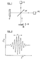
- Figure 1 of the accompanying drawings shows such interferometer. It has a large S light source spectral band therefore having a short length of consistency.
- the beam from this source is conducted on a beam splitter SF which splits the beam from the source in a beam illuminating an object O to be studied and a beam striking a mirror M called reference.
- the striking beam the object O and the beam falling on the mirror M are respectively reflected and led through the SF separator to recombine and illuminate a PC photosensor.
- these reflected beams constructively and destructively interfere with each other by forming an interference fringe insofar as the difference in optical distances traveled is less to the coherence length of the source.
- This interferometric device thus allows to obtain an indication for example on the nature of the surface of the object.
- this interferometer does not make it possible to obtain a tomographic information of the object, i.e. a reflective information from several internal points to the object located deep.
- Such a scanning measurement process involving several measures spaced over time presents some disadvantages because besides the fact that the measurement is necessarily relatively long, it is found seriously disturbed if the object is subject to movements. This may be the case, for example in the medical field, which turned out to be an application particularly promising, and in particular, when measurements are carried out on certain constituents of the eye, like the cornea or retina.
- a mechanical element in motion what can result from vibrations and possibly a drop in performance during the time.
- Another disadvantage of this process is that the measurement relates only to points aligned one to others on an axis extending in depth and defining the direction of the reflected light beam by the object (deep reflection profile).
- the object of the invention is to provide a device kind of measurement briefly described above which allows instantly get the full result of the measure that it relates to an alignment of points in depth, on a deep slice of the object, even on a three-dimensional part of it.
- photosensors provide instantly set all intensity information interference fringes from different depths of the object, in other words, we can by a electronic analysis of the output signals of photosensors reconstitute a graph of the type of that of the figure 2 and without animating in any way the means of reference.
- Figures 3, 3A and 3B represent an exemplary embodiment of a system interferometric according to the invention making it possible to detect the characteristics of deep reflection of an object O.
- the system is said to be one-dimensional because it is able to collect measurement data only along a single Z axis supposed to cross the object. That is to say in the example, the measurement data are recorded in five points z0 to z4, point z0 being located for example on the front face, and point z4 on the back face of the object. Intermediate points z1, z2 and z3 can be representative of other places in the object where the reflective characteristics can translate its structure properties for example. The measurement record can thus inform the observer on typical characteristics of the object.
- the number of measurement points is only indicative, the system that can simultaneously capture many more points at a time, for example points z0 to zn.
- the number five was therefore chosen only to simplify the drawings.
- the interferometric device also includes a broadband and therefore low light source S consistency length.
- this SC source includes a superluminescent diode emitting on a 850 nm wavelength with a bandwidth of 20 nm.
- the source may also include an optical fiber single mode at 850 nm (not shown), to ensure that the beam is emitted in a single spatial mode.
- the device also includes a separator of beam SF, reference means M and means PC photosensors. These components are arranged in the same way so that in Figure 1, depending on the layout Michelson interferometric.
- the arms BM and BD are aligned on the Z axis and the arms BR and BS are aligned on a Y axis perpendicular to the Z axis and located in the same plane as this one (which is assumed to be the plane of the drawing in Figure 3).
- Y axes and Z intersect at the central point OC of the system.
- An axe X is defined perpendicular to this plane.
- the reference means M include a mirror having a plurality of mirrors elementary M0 to M4, here five in number, and arranged on a single optical unit presenting steps whose active faces are arranged perpendicular to the Y axis and parallel to the X axis.
- the means of reference M include as many steps as points of measure that we want to obtain along the Z axis in the object O. The steps thus define in the reference arm BR as many elementary reference beams FR0 to FR4 with different path lengths.
- the photosensor means PCs include a row of photosensor elements PC0 to PC4, here also five, the number depending the number of measurement points that we want to define in depth in object O. Note that the elements photosensors PC0 to PC4 are arranged side by side in their row parallel to the Y axis.
- the system interferometric includes a set of lenses L1 to L4 (see in particular Figures 3A and 3B).
- a first L1 of these lenses is collimator and provided in the source arm BS. It is placed in front of the source S and intended to form an image of it on the face of object O using lens L3 and on all the steps M0 to M4 of the reference means M using the L2 lens.
- the distance of lens L1 from the source S is preferably less than its distance focal in order to defocus the light spot on the object O and on the reference means M, in order to clarify the object O and the set of reference means M.
- the lenses L2, L3 and L4 form, with the SF separator, optical recombination means. They are determined in such a way that both each element photosensor PC0 to PC4 receives light from a position (xi, yi) of the object O via the object beam FO and that furthermore each photosensor element PC0 to PC4 does not receives light only from one level M0 to M4 from means of reference M.
- the couple of lenses L2, L4 located respectively in the arm of reference BR and in the detection arm BD projects a image of the reference means M on the elements photosensors PC0 to PC4 at the rate of one step per element photosensor.
- the pair of lenses L3, L4 located respectively in the BM measuring arm and the arm detection system projects an image of the object O onto all the photosensors PC0 to PC4.
- the focal lengths of L3 and L4 lenses will preferably be chosen so that f3 ⁇ f4, which will provide a resolution favorable in the direction of the X axis and the Y axis.
- elementary reference beams FR0 to FR4 and the beam FO thus projected interfere with each other others, so as to form an interference image which is received by the photosensors (PC0 to PC4).
- lenses L1 to L4 can be lenses spherical, preferably achromatic.
- the lenses could be replaced by light guides appropriate.
- the interferometric system according to the invention allows, with a single row of photosensors, to obtain by a single measurement instantaneous data per point in depth of the object (point z0 to z4) respectively at the rate of a given by photosensor element.
- the signals collected on the photosensor elements P0 to P4 can be used in processing them in the MA operating system, according to the results that we ultimately want to achieve, certain ways of treating them being described by the after.
- Figure 4 shows a sketch of a second exemplary embodiment of the invention in which the interferometric system is of the two-dimensional type.
- direction X In others terms, it becomes possible to collect data on a "slice" of the object indicated by oblique lines on FIG. 4 in order to release optical data according to a profile.
- FIGS. 5A to 8B make it possible to analyze according to a representation aligned the arms of the device interferometric respectively seen in elevation and in plan, according to figure 4.
- the figures show the lengths focal lengths of lenses L1 to L4 and their general shapes as well as the general path of the beams. For which relates to FIGS. 7A to 8B, only a few beams so as not to overload the figures.
- These figures also show that a diaphragm D can be placed in the detection arm BD next to the separator SF. The opening of this diaphragm is chosen in such a way that the spot of light that arrives on the surface of a photosensor stays inside a single cone of diffraction. This condition guarantees detection optimal interference fringes.
- Such a diaphragm can also be used in the figure interferometer 3, as shown.
- Figures 5A to 8B also show benchmarks identifying object points and photosensors correspondents with the identification of steps Z0 to Z4 reference means M.
- the number of measurement points in depth can be much greater than five (from z0 to zn), as well as the number of points in height according to the direction X (from x0 to xm).
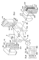
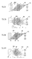
- Figure 9 is a schematic representation of a example of arrangement of rotated PC photosensor means to the SF separator, according to one embodiment particularly interesting of the invention. Indeed, according to a particularly advantageous characteristic of the invention it is possible to extend the device two-dimensional interferometric to a device three-dimensional by means of two extremely additions simple.
- a plurality is provided here of matrices identified by the references y0 to yp and of place these matrices side by side along the Y axis of the device.
- a plurality of reference means placed side by side along the Z axis of the device.
- each of the matrices of photosensor elements will receive the image of a plan of reflection of the object, the planes being arranged in parallel one behind the other along the Z axis.
- PC means optical data in a volume of the object O and this, instantly without any mechanical manipulation spread out in time is not necessary.
- the measurement time does will be determined only by how quickly the electronic means of MA analysis.
- memory means for recording the data supplied by the PC photosensors before we start electronic analysis So it doesn't matter if the object is subject to movement, the acquisition time of the means photosensors and the memory being almost snapshots. This also applies equally to one-dimensional and two-dimensional embodiments.
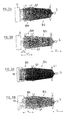
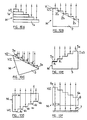
- Figure 10A shows a first possible variant reference means M in which these are formed by a plurality of mirrors 1a to 1n superimposed and offset, the step ⁇ z between two adjacent measurable points in depth being determined by the thickness hl of the mirrors elementary 1a to 1n.
- Figure 10B shows a second variant in which the reference means M comprise a network of diffraction with notches 2 (called “blazed grating”) in the Anglo-Saxon literature) whose angle ⁇ 1 defines the angle (“blazed angle”) and whose dimension h2 of the notches 2a to 2n defines the step ⁇ z which is the optical distance between two adjacent points measurable in depth in the object O.
- the reference means M comprise a network of diffraction with notches 2 (called “blazed grating") in the Anglo-Saxon literature) whose angle ⁇ 1 defines the angle (“blazed angle”) and whose dimension h2 of the notches 2a to 2n defines the step ⁇ z which is the optical distance between two adjacent points measurable in depth in the object O.
- blazed grating a network of diffraction with notches 2
- the reference means comprise a matrix 3 of retroreflectors 3a to 3n, (called “corner cubes” in Anglo-Saxon literature) in the shape of pyramids with a rectangular base.
- the angle ⁇ 2 defines the inclination of the plane of the bases of retroreflectors from the perpendicular direction to elementary beams.
- the dimension h3 indicates the pitch ⁇ z.
- FIG. 10D shows another form in which the reference means can be produced.
- a block 4 in a transparent medium is cut in "staircase" on its rear face, reflective deposits facing the opposite face of the block 4 being made on the steps 4a to 4n thus obtained.
- These steps form light coming from the source S as many elementary reference beams.
- the advantage of this variant is that it allows, by choosing a material with a refractive index n close to that of the object O, to reduce the loss in resolution due to the scattering of light in the reference arms and measurement of the interferometer.
- FIG. 10E takes the form of that of FIG. 10B. It includes a block 5 whose rungs are coated with reflective deposits 5a to 5n.
- the reflection coefficients Ra to Rn of these deposits are chosen according to the local nature of the points in depth of the object to be examined.
- An application example such reference means is encountered for example, for in-depth examination of the eye including the retina and cornea have very high reflection coefficients dissimilar, differences that these benchmarks allow to compensate by choosing coefficients of reflection determined for deposits.
- FIG. 10F represents a variant of means of benchmarks that operate by transparency.
- a block 6 in a transparent medium is cut in steps to form steps 6a to 6n.
- This block is placed in alignment of the source S and behind its opposite face is arranged a flat reflecting surface 7.
- the pitch of depth ⁇ z is equal to that of the variant in the figure 10D.
- Block 6 can also be used in a realization of the interferometric device according to the invention in which the reference means M and beams of light pass through the object.
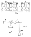
- a variant of such a device is shown in the figure 11 which does not require further comments except that the results obtained are similar to those described in reference to Figures 3, 4 and 9, respectively.
- Mach-Zehnder type interferometers well known to specialists. It includes two beam splitters SF1 and SF2 and two deflection mirrors M1 and M2.
- the step ⁇ z corresponding to an interference fringe is related to the wavelength of the source and is equal to ⁇ / 2.
- FIG. 12 illustrates an analysis direct signals obtained which can be executed by the MA analysis means.
- a maximum may not coincide with a photodetector element of the matrix.
- phase shifter or a phase modulator either in the BM measurement arm, ie in the reference arm BR.
- This phase shifter or phase modulator can be a cell with liquid crystal for example controlled by a voltage electric. It is schematically dotted in DPH on the figure 4, but it can also be provided in the interferometer in Figure 3.
- a picture is acquired on the matrix of PC photosensor elements. Then, a phase shift is produced by applying the voltage electric to the phase-shifter or DPH phase modulator. A new image is acquired on the photosensor matrix PC. Then, the analysis means MA carry out a selective subtraction of signals obtained from two successive images.
- the means of analysis provide a nonzero signal only at locations Z where there are interference. This method allows you to view the interference fringes but not necessarily getting the maximum intensity of a fringe.
- the difference between the optical length during the first measurement and that resulting from the phase shift must be chosen different from a multiple of 2 ⁇ .
- This method allows to use only 2 to 3 detectors by group of interference fringes, it being understood that the length (spatial spread) of a group of fringes is determined by the coherence length Lc of the source S. However, it requires two successive measurements, it is true very close together over time.
- the amplitude of an interference fringe can also be detected by time sampling.
- the phase shifter or phase modulator DPH is also provided, either in the reference arm BR or in the measurement arm BM.
- the value of the phase is taken with respect to the mean wavelength of the source S.
- I o [ ⁇ i I i - I avg 2 ] 1 2 .
- the three analysis methods which have just been have the advantage of allowing the use of standard photosensor arrays, such as a camera CCD, APS active matrices etc.
- the DPH phase shifter or phase modulator can be used to modulate the phase of the light either in the measuring arm, either in the reference arm of a periodically, for example sinusoidal.
- the analysis means are advantageously carried out according to the method described in the article by Swanson et al. appeared in "Optics Letters" Jan. 15, 1992, Vol 17, no 2.
- the source S can be unique as described so far. However, it is also possible to use a line sources, even a matrix. As a result, more of light energy becomes available per element photosensor, which provides a better ratio signal / noise.
- each beam illuminates a position along the X axis of the sample and illuminates all elementary mirrors z0 to zn means of reference.
- Each beam of the BM measuring arm is recombined with its series of reference arm beams BR.
- each line of n beams of sources illuminates a position according to the X axis of the object O and illuminates all the positions z0 to zn (along the Z axis) of the reference means, at the rate of a elementary source by position.
- Each beam of the arm of BM measurement is recombined with its reference beam associated.
- Suitable light sources are diodes side-emitting electroluminescent, laser diodes, stacks of laser diode arrays or diodes or arrays of laser diodes with vertical cavities.
- Diodes electroluminescent or other sources emitting non-coherent light (tungsten filament) can also be used with circular diaphragms or rectangular.
Abstract
Description
La présente invention est relative à l'acquisition d'images par tomographie optique par laquelle il est possible d'obtenir des images formées par les intensités de rayons lumineux provenant d'un objet à étudier, ces intensités étant fonction de la profondeur dans celui-ci. Ces intensités optiques peuvent être obtenues, soit par réflexion des rayons sur ou dans l'objet, soit par transmission de lumière à travers cet objet.The present invention relates to the acquisition of images by optical tomography by which it is possible to obtain images formed by the intensities of light rays coming from an object to be studied, these intensities being a function of the depth therein. These optical intensities can be obtained either by reflection of rays on or in the object, either by transmission of light through this object.
Plus précisément, l'invention concerne le domaine de l'interférométrie dite "à basse cohérence" et utilise le principe de l'interféromètre de Michelson.More specifically, the invention relates to the field of so-called "low coherence" interferometry and uses the principle of the Michelson interferometer.
La figure 1 des dessins annexés représente un tel interféromètre. Il comporte une source de lumière S à large bande spectrale ayant par conséquent une faible longueur de cohérence. Le faisceau issu de cette source est conduit sur un séparateur de faisceau SF qui divise le faisceau de la source en un faisceau éclairant un objet O à étudier et un faisceau frappant un miroir M dit de référence.Figure 1 of the accompanying drawings shows such interferometer. It has a large S light source spectral band therefore having a short length of consistency. The beam from this source is conducted on a beam splitter SF which splits the beam from the source in a beam illuminating an object O to be studied and a beam striking a mirror M called reference.
Dans le cas de cette figure, le faisceau frappant l'objet O et le faisceau tombant sur le miroir M sont respectivement réfléchis et conduits à travers le séparateur SF pour se recombiner et illuminer un photocapteur PC. Ce faisant, ces faisceaux réfléchis interfèrent entre eux constructivement et destructivement en formant une frange d'interférence dans la mesure où la différence des distances optiques parcourues est inférieure à la longueur de cohérence de la source.In the case of this figure, the striking beam the object O and the beam falling on the mirror M are respectively reflected and led through the SF separator to recombine and illuminate a PC photosensor. In doing so, these reflected beams constructively and destructively interfere with each other by forming an interference fringe insofar as the difference in optical distances traveled is less to the coherence length of the source.
Ce dispositif interférométrique permet ainsi d'obtenir une indication par exemple sur la nature de la surface de l'objet. Cependant, tel qu'il vient d'être décrit, cet interféromètre ne permet pas d'obtenir une information tomographique de l'objet, c'est-à-dire une information due à la réflexion provenant de plusieurs points internes à l'objet situés en profondeur.This interferometric device thus allows to obtain an indication for example on the nature of the surface of the object. However, as it has just been described, this interferometer does not make it possible to obtain a tomographic information of the object, i.e. a reflective information from several internal points to the object located deep.
Pour obtenir une telle information en profondeur, il est déjà connu de procéder à un balayage en profondeur (voir par exemple à cet égard l'article de E.A. Swanson et al. dans la revue OPTICS LETTERS/Vol. 18, No. 21/november 1,1993). Dans ce cas, l'interféromètre est réalisé à l'aide de fibres optiques et de coupleurs, ce qui ne change pas fondamentalement le principe de la mesure. Cependant, pour obtenir une information à partir de différentes profondeurs de l'objet, on procède à des prises de mesure successives en changeant à chaque fois la position du miroir de référence de manière à modifier la longueur du trajet optique dans le bras du dispositif contenant ce miroir (appelé ci-après bras de référence). Sur la figure 1, ce mouvement est symbolisé par la flèche B.To obtain such in-depth information, it is already known to perform a deep scan (see for example in this regard the article by E.A. Swanson and al. in the journal OPTICS LETTERS / Vol. 18, No. 21 / November 1.1993). In this case, the interferometer is performed using fiber optics and couplers, which doesn't change basically the principle of measurement. However, for get information from different depths of the object, we take successive measurements by changing the position of the mirror each time reference in order to modify the path length optic in the arm of the device containing this mirror (hereinafter called reference arm). In Figure 1, this movement is symbolized by the arrow B.
On obtient ainsi un graphe d'interférence tel que représenté sur la figure 2 lorsque l'objet O correspond à une interface où l'intensité lumineuse I frappant le photocapteur PC est portée en ordonnées et la position longitudinale du miroir de référence M en abscisses (appelée par convention position en z qui reflète aussi la position en profondeur du point de l'objet ayant donné lieu à la frange d'interférence considérée). Il est à noter que la résolution de la mesure dépend de la longueur de cohérence de la source S indiquée par la flèche Lc.We thus obtain an interference graph such that shown in Figure 2 when the object O corresponds to an interface where the light intensity I striking the PC photosensor is plotted on the ordinate and the position longitudinal of the reference mirror M on the abscissa (conventionally called position in z which also reflects the position in depth of the point of the object which gave rise at the interference fringe considered). It is to highlight that the resolution of the measurement depends on the length of coherence of the source S indicated by the arrow Lc.
Un tel processus de mesure par balayage impliquant plusieurs mesures espacées dans le temps, présente certains inconvénients, car outre le fait que la mesure est nécessairement relativement longue, elle se trouve sérieusement perturbée si l'objet est sujet à des mouvements. Ceci peut être le cas, par exemple dans le domaine médical, qui s'est révélé être une application particulièrement prometteuse, et notamment, lorsque des mesures sont effectuées sur certains constituants de l'oeil, comme la cornée ou la rétine. En outre, pour déplacer le miroir, il faut utiliser un élément mécanique en mouvement ce dont il peut résulter des vibrations et éventuellement une baisse des performances au cours du temps.Such a scanning measurement process involving several measures spaced over time, presents some disadvantages because besides the fact that the measurement is necessarily relatively long, it is found seriously disturbed if the object is subject to movements. This may be the case, for example in the medical field, which turned out to be an application particularly promising, and in particular, when measurements are carried out on certain constituents of the eye, like the cornea or retina. In addition, for move the mirror, use a mechanical element in motion what can result from vibrations and possibly a drop in performance during the time.
Un autre inconvénient de ce processus consiste en ce que la mesure ne porte que sur des points alignés les uns aux autres sur un axe s'étendant en profondeur et définissant la direction du faisceau de lumière réfléchi par l'objet (profil de réflexion en profondeur).Another disadvantage of this process is that that the measurement relates only to points aligned one to others on an axis extending in depth and defining the direction of the reflected light beam by the object (deep reflection profile).
Ainsi, pour obtenir l'image d'une tranche en profondeur de l'objet, il faut effectuer successivement des séries de mesures comme décrites ci-dessus, que l'on peut qualifier d'unidimensionnelles mais déplacées latéralement l'une par rapport à l'autre, pour obtenir des groupes de valeurs d'intensité qu'il faut ensuite traiter pour transformer ces séries de mesures unidimensionnelles en un résultat bidimensionnel représentatif du profil d'une tranche de l'objet. Il est clair que cette procédure aggrave les inconvénients de la mesure unidimensionnelle en termes de durée de mesure et de susceptibilité aux mouvements de l'objet.So, to get the image of a slice in depth of the object, successive series of measures as described above, which can be qualify as one-dimensional but displaced laterally relative to each other, to get groups of intensity values which must then be processed to transform these series of one-dimensional measurements into one two-dimensional result representative of the profile of a slice of the object. It is clear that this procedure aggravates the disadvantages of one-dimensional measurement in terms of measurement time and susceptibility to object movements.
L'invention a pour objectif de fournir un dispositif de mesure du genre brièvement décrit ci-dessus qui permette d'obtenir instantanément la totalité du résultat de la mesure que celle-ci porte sur un alignement de points en profondeur, sur une tranche en profondeur de l'objet, voire sur une partie tridimensionnelle de celui-ci.The object of the invention is to provide a device kind of measurement briefly described above which allows instantly get the full result of the measure that it relates to an alignment of points in depth, on a deep slice of the object, even on a three-dimensional part of it.
L'invention a donc pour objet un dispositif interférométrique pour relever les caractéristiques de réflexion et/ou de transmission optiques en profondeur d'un objet par interférométrie, comprenant :
- une source de lumière émettant sur une bande spectrale prédéterminée de part et d'autre d'une longueur d'onde nominale et éclairant ledit objet de manière à créer un faisceau objet provenant de celui-ci,
- des moyens de référence également exposés à ladite source pour créer un faisceau de référence,
- des moyens pour faire interférer lesdits faisceaux objet et de référence; et
- des moyens photocapteurs agencés pour recevoir la lumière due à l'interférence desdits faisceaux objet et de référence, et des moyens d'analyse (MA) pour exploiter les signaux fournis par lesdits moyens photocapteurs,
- a light source emitting on a predetermined spectral band on either side of a nominal wavelength and illuminating said object so as to create an object beam originating therefrom,
- reference means also exposed to said source to create a reference beam,
- means for interfering said object and reference beams; and
- photosensor means arranged to receive the light due to the interference of said object and reference beams, and analysis means (MA) for exploiting the signals supplied by said photosensor means,
Il résulte de ces caractéristiques que, lors d'une mesure unidimensionnelle, les photocapteurs fournissent ensemble instantanément toutes les informations d'intensité des franges d'interférence provenant de différentes profondeurs de l'objet, autrement dit, on peut par une analyse électronique des signaux de sortie des photocapteurs reconstituer un graphe du type de celui de la figure 2 et ce sans animer d'aucune manière les moyens de référence.It follows from these characteristics that, during a one-dimensional measurement, photosensors provide instantly set all intensity information interference fringes from different depths of the object, in other words, we can by a electronic analysis of the output signals of photosensors reconstitute a graph of the type of that of the figure 2 and without animating in any way the means of reference.
D'autres caractéristiques et avantages de l'invention apparaítront au cours de la description qui va suivre, donnée uniquement à titre d'exemple et faite en se référant aux dessins annexés sur lesquels :
- la figure 1, déjà décrite, est une représentation schématique d'un interféromètre de Michelson classique pouvant être utilisé pour la tomographie optique;
- la figure 2, également déjà décrite, montre un graphe illustrant le fonctionnement de l'interféromètre classique de la figure 1;
- la figure 3 est un schéma montrant les composants formant un interféromètre tomographique unidimensionnel selon l'invention;
- la figure 3A est un schéma montrant les trajets des faisceaux réfléchis par l'objet O et les moyens de référence M dans l'interféromètre de la figure 3;
- la figure 3B est un schèma analogue à celui de la figure 3A, mais montrant l'illumination de l'objet O et des moyens de référence M par la source S;
- la figure 4 est un schéma dessiné en perspective d'un interféromètre tomographique selon l'invention permettant d'effectuer des mesures bidimensionnelles pour obtenir des informations optiques sur une "tranche" de l'objet;
- les figures 4A et 4B montrent schématiquement deux variantes de réalisation possibles de la source de lumière;
- les figures 5A et 5B sont des vues schématiques, respectivement en vue en élévation et en vue en plan de la figure 4 et selon une représentation alignée des axes concernés, qui ne sert qu'à clarifier la structure du dispositif, des bras de mesure et de source du dispositif interférométrique selon l'invention, afin de mettre en évidence les trajets des rayons lumineux dans ces bras;
- les figures 6A et 6B sont des vues schématiques analogues à celles des figures 5A et 5B, montrant alignés le bras de référence et le bras de source;
- les figures 7A et 7B sont des vues analogues aux précédentes et représentant alignés les bras de mesure et de détection;
- les figures 8A et 8B sont des vues analogues aux précédentes, mais montrant le bras de référence aligné sur le bras de détection;
- la figure 9 est une représentation schématique d'un exemple de disposition de moyens photocapteurs utilisés pour réaliser un dispositif interférométrique tridimensionnel selon l'invention;
- les figures 10A à 10F montrent plusieurs variantes possibles des moyens de référence du dispositif interférométrique selon l'invention;
- la figure 11 montre un schéma de principe d'un dispositif interférométrique travaillant en transmission et
- la figure 12 est un graphe de l'intensité I en fonction de la profondeur dans un objet, pour illustrer une méthode d'analyse particulière pouvant être utilisée pour la mise en oeuvre du dispositif interférométrique selon l'invention.
- Figure 1, already described, is a schematic representation of a conventional Michelson interferometer which can be used for optical tomography;
- FIG. 2, also already described, shows a graph illustrating the operation of the conventional interferometer of FIG. 1;
- FIG. 3 is a diagram showing the components forming a one-dimensional tomographic interferometer according to the invention;
- FIG. 3A is a diagram showing the paths of the beams reflected by the object O and the reference means M in the interferometer of FIG. 3;
- FIG. 3B is a diagram similar to that of FIG. 3A, but showing the illumination of the object O and of the reference means M by the source S;
- FIG. 4 is a diagram drawn in perspective of a tomographic interferometer according to the invention making it possible to carry out two-dimensional measurements to obtain optical information on a "slice" of the object;
- FIGS. 4A and 4B schematically show two possible alternative embodiments of the light source;
- FIGS. 5A and 5B are schematic views, respectively in elevation view and in plan view of FIG. 4 and according to an aligned representation of the axes concerned, which only serves to clarify the structure of the device, of the measurement arms and from the source of the interferometric device according to the invention, in order to highlight the paths of the light rays in these arms;
- Figures 6A and 6B are schematic views similar to those of Figures 5A and 5B, showing aligned the reference arm and the source arm;
- FIGS. 7A and 7B are views similar to the previous ones and showing the measurement and detection arms aligned;
- FIGS. 8A and 8B are views similar to the previous ones, but showing the reference arm aligned with the detection arm;
- FIG. 9 is a schematic representation of an exemplary arrangement of photosensor means used to produce a three-dimensional interferometric device according to the invention;
- FIGS. 10A to 10F show several possible variants of the reference means of the interferometric device according to the invention;
- FIG. 11 shows a block diagram of an interferometric device working in transmission and
- FIG. 12 is a graph of the intensity I as a function of the depth in an object, to illustrate a particular analysis method which can be used for the implementation of the interferometric device according to the invention.
On va maintenant se référer aux figures 3, 3A et 3B, qui représentent un exemple de réalisation d'un système interférométrique selon l'invention permettant de relever les caractéristiques de réflexion en profondeur d'un objet O. Dans cet exemple, le système est dit unidimensionnel car il est capable de ne relever des données de mesure que selon un seul axe Z supposé traverser l'objet. C'est-à-dire dans l'exemple, les données de mesure sont relevées en cinq points z0 à z4, le point z0 étant situé par exemple sur la face avant, et le point z4 sur la face arrière de l'objet. Les points intermédiaires z1, z2 et z3 peuvent être représentatifs d'autres endroits de l'objet où les caractéristiques de réflexion peuvent traduire ses propriétés de structure par exemple. Le relevé des mesures effectuées peut ainsi renseigner l'observateur sur des caractéristiques typiques de l'objet.We will now refer to Figures 3, 3A and 3B, which represent an exemplary embodiment of a system interferometric according to the invention making it possible to detect the characteristics of deep reflection of an object O. In this example, the system is said to be one-dimensional because it is able to collect measurement data only along a single Z axis supposed to cross the object. That is to say in the example, the measurement data are recorded in five points z0 to z4, point z0 being located for example on the front face, and point z4 on the back face of the object. Intermediate points z1, z2 and z3 can be representative of other places in the object where the reflective characteristics can translate its structure properties for example. The measurement record can thus inform the observer on typical characteristics of the object.
Le nombre de points de mesure n'est qu'indicatif, le système pouvant relever simultanément bien davantage de points à la fois par exemple les points z0 à zn. Le nombre cinq a donc été choisi uniquement pour simplifier les dessins.The number of measurement points is only indicative, the system that can simultaneously capture many more points at a time, for example points z0 to zn. The number five was therefore chosen only to simplify the drawings.
Le dispositif interférométrique comporte également une source de lumière S à large bande et donc à faible longueur de cohérence. A titre d'exemple, cette source SC comprend une diode superluminescente émettant sur une longueur d'onde de 850 nm avec une largeur de bande de 20 nm. La source peut également comprendre une fibre optique monomode à 850 nm (non représentée), afin de garantir que le faisceau soit émis dans un seul mode spatial.The interferometric device also includes a broadband and therefore low light source S consistency length. As an example, this SC source includes a superluminescent diode emitting on a 850 nm wavelength with a bandwidth of 20 nm. The source may also include an optical fiber single mode at 850 nm (not shown), to ensure that the beam is emitted in a single spatial mode.
Le dispositif comprend également un séparateur de faisceau SF, des moyens de référence M et des moyens photocapteurs PC. Ces composants sont agencés de la même façon que sur la figure 1, selon la disposition interférométrique de Michelson.The device also includes a separator of beam SF, reference means M and means PC photosensors. These components are arranged in the same way so that in Figure 1, depending on the layout Michelson interferometric.
Pour la commodité de la description, on appellera
- bras de mesure BM, la partie du dispositif s'étendant entre le séparateur SF et l'objet O;
- bras de référence BR, la partie située entre le séparateur SF et les moyens de référence M;
- bras de source BS, la partie située entre le séparateur SF et la source S; et
- bras de détection BD, la partie située entre le séparateur SF et les moyens photocapteurs PC.
- BM measurement arm, the part of the device extending between the separator SF and the object O;
- reference arm BR, the part located between the separator SF and the reference means M;
- source arm BS, the part located between the separator SF and the source S; and
- BD detection arm, the part located between the separator SF and the photosensor means PC.
Les bras BM et BD sont alignés sur l'axe Z et les bras BR et BS sont alignés sur un axe Y perpendiculaire à l'axe Z et situé dans le même plan que celui-ci (qui est supposé être le plan du dessin de la figure 3). Les axes Y et Z se croisent en le point central OC du système. Un axe X est défini perpendiculairement à ce plan. The arms BM and BD are aligned on the Z axis and the arms BR and BS are aligned on a Y axis perpendicular to the Z axis and located in the same plane as this one (which is assumed to be the plane of the drawing in Figure 3). Y axes and Z intersect at the central point OC of the system. An axe X is defined perpendicular to this plane.
Selon l'invention, les moyens de référence M comprennent un miroir présentant une pluralité de miroirs élémentaires M0 à M4, ici au nombre de cinq, et agencés sur un bloc optique unique présentant des échelons dont les faces actives sont disposées perpendiculairement à l'axe Y et parallèlement à l'axe X. Généralement, les moyens de référence M comprennent autant d'échelons que de points de mesure que l'on souhaite obtenir selon l'axe Z dans l'objet O. Les échelons définissent ainsi dans le bras de référence BR autant de faisceaux de référence élémentaires FR0 à FR4 dont les longueurs de trajet sont différentes.According to the invention, the reference means M include a mirror having a plurality of mirrors elementary M0 to M4, here five in number, and arranged on a single optical unit presenting steps whose active faces are arranged perpendicular to the Y axis and parallel to the X axis. Generally, the means of reference M include as many steps as points of measure that we want to obtain along the Z axis in the object O. The steps thus define in the reference arm BR as many elementary reference beams FR0 to FR4 with different path lengths.
Selon l'invention également, les moyens photocapteurs PC comprennent une rangée d'éléments photocapteurs PC0 à PC4, ici également au nombre de cinq, le nombre dépendant du nombre de points de mesure que l'on veut définir en profondeur dans l'objet O. On notera que les éléments photocapteurs PC0 à PC4 sont agencés côte-à-côte dans leur rangée parallèlement à l'axe Y.According to the invention also, the photosensor means PCs include a row of photosensor elements PC0 to PC4, here also five, the number depending the number of measurement points that we want to define in depth in object O. Note that the elements photosensors PC0 to PC4 are arranged side by side in their row parallel to the Y axis.
Par ailleurs, toujours selon l'invention, le système interférométrique comprend un jeu de lentilles L1 à L4 (voir notamment les figures 3A et 3B).Furthermore, still according to the invention, the system interferometric includes a set of lenses L1 to L4 (see in particular Figures 3A and 3B).
Une première L1 de ces lentilles est collimatrice et prévue dans le bras de source BS. Elle est placée devant la source S et destinée à former une image de celle-ci sur la face de l'objet O à l'aide de la lentille L3 et sur tous les échelons M0 à M4 des moyens de référence M à l'aide de la lentille L2. La distance de la lentille L1 par rapport à la source S est de préférence inférieure à sa distance focale afin de défocaliser le spot lumineux sur l'objet O et sur les moyens de référence M, dans le but d'éclairer l'objet O et l'ensemble des moyens de référence M.A first L1 of these lenses is collimator and provided in the source arm BS. It is placed in front of the source S and intended to form an image of it on the face of object O using lens L3 and on all the steps M0 to M4 of the reference means M using the L2 lens. The distance of lens L1 from the source S is preferably less than its distance focal in order to defocus the light spot on the object O and on the reference means M, in order to clarify the object O and the set of reference means M.
De plus, les lentilles L2, L3 et L4 forment, avec le séparateur SF, des moyens de recombinaison optique. Ils sont déterminés de telle façon qu'à la fois chaque élément photocapteur PC0 à PC4 reçoive de la lumière d'une position (xi, yi) de l'objet O par l'intermédiaire du faisceau objet FO et qu'en outre chaque élément photocapteur PC0 à PC4 ne reçoive de la lumière que d'un seul échelon M0 à M4 des moyens de référence M. En d'autres termes, le couple de lentilles L2, L4 situées respectivement dans le bras de référence BR et dans le bras de détection BD, projette une image des moyens de référence M sur les éléments photocapteurs PC0 à PC4 à raison d'un échelon par élément photocapteur. De son côté, le couple de lentilles L3, L4, situées respectivement dans le bras de mesure BM et le bras de détection BD projette une image de l'objet O sur l'ensemble des photocapteurs PC0 à PC4. Les focales des lentilles L3 et L4 seront de préférence choisies de manière que f3 << f4, ce qui permettra d'obtenir une résolution favorable dans le sens de l'axe X et de l'axe Y. Les faisceaux de référence élémentaires FR0 à FR4 et le faisceau FO ainsi projetés interfèrent les uns avec les autres, de manière à former une image d'interférence qui est reçue par les photocapteurs (PC0 à PC4).In addition, the lenses L2, L3 and L4 form, with the SF separator, optical recombination means. They are determined in such a way that both each element photosensor PC0 to PC4 receives light from a position (xi, yi) of the object O via the object beam FO and that furthermore each photosensor element PC0 to PC4 does not receives light only from one level M0 to M4 from means of reference M. In other words, the couple of lenses L2, L4 located respectively in the arm of reference BR and in the detection arm BD, projects a image of the reference means M on the elements photosensors PC0 to PC4 at the rate of one step per element photosensor. For its part, the pair of lenses L3, L4, located respectively in the BM measuring arm and the arm detection system projects an image of the object O onto all the photosensors PC0 to PC4. The focal lengths of L3 and L4 lenses will preferably be chosen so that f3 << f4, which will provide a resolution favorable in the direction of the X axis and the Y axis. elementary reference beams FR0 to FR4 and the beam FO thus projected interfere with each other others, so as to form an interference image which is received by the photosensors (PC0 to PC4).
L'obtention de ce résultat apparaít clairement aux spécialistes qui sauront déterminer selon ces règles les caractéristiques des lentilles à utiliser. Pour fixer les idées, les lentilles L1 à L4 peuvent être des lentilles sphériques, de préférence achromatiques.Obtaining this result is clearly apparent to specialists who will be able to determine according to these rules the characteristics of the lenses to be used. To fix the ideas, lenses L1 to L4 can be lenses spherical, preferably achromatic.
Il est à noter que selon une variante, les lentilles pourraient être remplacées par des guides de lumière appropriés.It should be noted that according to a variant, the lenses could be replaced by light guides appropriate.
Le système interférométrique selon l'invention que l'on vient de décrire permet, avec une seule rangée d'éléments photocapteurs, d'obtenir par une seule mesure instantanée une donnée par point en profondeur de l'objet (point z0 à z4) respectivement à raison d'une donnée par élément photocapteur. Les signaux recueillis sur les éléments photocapteurs P0 à P4 peuvent être exploités en les traitant dans le dispositif d'exploitation MA, selon les résultats que l'on souhaite finalement obtenir, certaines façons de les traiter étant décrites par la suite.The interferometric system according to the invention that just described allows, with a single row of photosensors, to obtain by a single measurement instantaneous data per point in depth of the object (point z0 to z4) respectively at the rate of a given by photosensor element. The signals collected on the photosensor elements P0 to P4 can be used in processing them in the MA operating system, according to the results that we ultimately want to achieve, certain ways of treating them being described by the after.
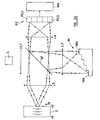
La figure 4 représente un esquisse d'un second exemple de réalisation de l'invention dans lequel le système interférométrique est de type bidimensionnel. Dans le cadre de l'invention, cela veut dire qu'il est capable de fournir des données optiques relatives, non seulement à des points de l'objet situés en profondeur (le long de l'axe Z) mais également selon une autre direction qui, dans l'exemple représenté, est la direction X. En d'autres termes, il devient possible de relever des données sur une "tranche" de l'objet indiquée par des traits obliques sur la figure 4 afin de dégager des données optiques selon un profil.Figure 4 shows a sketch of a second exemplary embodiment of the invention in which the interferometric system is of the two-dimensional type. In the scope of the invention, this means that it is capable to provide optical data relating not only to deep object points (along the Z axis) but also in another direction which, in the example shown is direction X. In others terms, it becomes possible to collect data on a "slice" of the object indicated by oblique lines on FIG. 4 in order to release optical data according to a profile.
Le système de mesure de la figure 4 diffère essentiellement de celui de la figure 3 sur trois points (étant entendu que de nouveau, pour simplifier, on a limité le nombre de points relevés à cinq en profondeur et cinq selon la direction X):
- les moyens de référence M s'étendent dans la direction de l'axe X sur une hauteur telle que des faisceaux de référence élémentaires provenant des échelons M0 à M4 puissent être dirigés sur les cinq zones en X des moyens photocapteurs PC;
- les moyens photocapteurs PC comprennent une matrice d'éléments photocapteurs s'étendant selon les directions X et Y (ici naturellement à raison de cinq éléments par direction);
- les moyens de recombinaison comprennent, à la place de la lentille L3 de la figure 3, deux lentilles distinctes L3' et L3'' de forme cylindrique et dont les axes sont respectivement parallèles à la direction X et à la direction Y. Les faces convexes de ces lentilles L3' et L3" sont tournées vers le séparateur SF. Comme dans le cas de la figure 3, les focales L3' et L4 seront de préférence choisies de manière que f3'<<f4, ce qui permettra d'obtenir une résolution favorable dans la direction Y.
- the reference means M extend in the direction of the axis X over a height such that elementary reference beams coming from the steps M0 to M4 can be directed onto the five areas in X of the photosensor means PC;
- the photosensor means PC comprise a matrix of photosensor elements extending in the directions X and Y (here naturally at the rate of five elements per direction);
- the recombination means comprise, in place of the lens L3 of FIG. 3, two separate lenses L3 'and L3''of cylindrical shape and whose axes are respectively parallel to the X direction and to the Y direction. The convex faces of these lenses L3 'and L3 "are turned towards the separator SF. As in the case of FIG. 3, the focal lengths L3' and L4 will preferably be chosen so that f3 '<< f4, which will make it possible to obtain a favorable resolution in direction Y.
Les figures 5A à 8B permettent d'analyser selon une
représentation alignées les bras du dispositif
interférométrique respectivement vu en élévation et en
plan, selon la figure 4. Les figures montrent les longueurs
focales des lentilles L1 à L4 et leurs formes générales
ainsi que le cheminement général des faisceaux. Pour ce qui
concerne les figures 7A à 8B, on n'a représenté que
quelques faisceaux pour ne pas trop charger les figures.
Ces figures montrent également qu'un diaphragme D peut être
placé dans le bras de détection BD à côté du séparateur SF.
L'ouverture de ce diaphragme est choisie de telle manière
que le spot de lumière qui arrive sur la surface d'un
photocapteur reste à l'intérieur d'un seul cône de
diffraction. Cette condition garantit une détection
optimale des franges d'interférence. Un tel diaphragme peut
également être utilisé dans l'interféromètre de la figure
3, comme représenté.FIGS. 5A to 8B make it possible to analyze according to a
representation aligned the arms of the device
interferometric respectively seen in elevation and in
plan, according to figure 4. The figures show the lengths
focal lengths of lenses L1 to L4 and their general shapes
as well as the general path of the beams. For which
relates to FIGS. 7A to 8B, only
a few beams so as not to overload the figures.
These figures also show that a diaphragm D can be
placed in the detection arm BD next to the separator SF.
The opening of this diaphragm is chosen in such a way
that the spot of light that arrives on the surface of a
photosensor stays inside a single cone of
diffraction. This condition guarantees detection
optimal interference fringes. Such a diaphragm can
also be used in the
Les figures 5A à 8B montrent également des repères identifiant les points d'objet et les photocapteurs correspondants avec l'identification des échelons Z0 à Z4 des moyens de référence M.Figures 5A to 8B also show benchmarks identifying object points and photosensors correspondents with the identification of steps Z0 to Z4 reference means M.
On notera également que le nombre de points de mesure en profondeur peut être très supérieur à cinq (de z0 à zn), de même que le nombre de points en hauteur selon la direction X (de x0 à xm).It should also be noted that the number of measurement points in depth can be much greater than five (from z0 to zn), as well as the number of points in height according to the direction X (from x0 to xm).
La figure 9 est une représentation schématique d'un exemple de disposition de moyens photocapteurs PC tournés vers le séparateur SF, selon un mode de réalisation particulièrement intéressant de l'invention. En effet, selon une caractéristique particulièrement avantageuse de l'invention, il est possible d'étendre le dispositif interférométrique bidimensionnel à un dispositif tridimensionnel moyennant deux adjonctions extrêmement simples. D'une part, au lieu d'une seule matrice de x0z0 à xmzn d'éléments photocapteurs, on prévoit ici une pluralité de matrices identifiées par les références y0 à yp et de placer ces matrices côte-à-côte selon l'axe Y du dispositif. D'autre part, on prévoit une pluralité de moyens de référence placés côte-à-côte selon l'axe Z du dispositif. Dans ces conditions, chacune des matrices d'éléments photocapteurs recevra l'image d'un plan de réflexion de l'objet, les plans étant agencés parallèlement les uns derrière les autres le long de l'axe Z. On peut ainsi recueillir sur les moyens photocapteurs PC des données optiques dans un volume de l'objet O et ce, instantanément sans qu'aucune manipulation mécanique étalée dans le temps ne soit nécessaire. Le temps de mesure ne sera déterminé que par la rapidité de fonctionnement des moyens électroniques d'analyse MA. Cependant, ceux-ci peuvent incorporer sans aucune difficulté majeure, des moyens de mémoire pour enregistrer les données fournies par les moyens photocapteurs PC avant que l'on n'en entreprenne l'analyse électronique. Peu importe donc que l'objet soit sujet à des mouvements, le temps d'acquisition des moyens photocapteurs et la mise en mémoire étant quasi instantanés. Ceci vaut d'ailleurs tout autant pour les modes de réalisation unidimensionnel et bidimensionnel.Figure 9 is a schematic representation of a example of arrangement of rotated PC photosensor means to the SF separator, according to one embodiment particularly interesting of the invention. Indeed, according to a particularly advantageous characteristic of the invention it is possible to extend the device two-dimensional interferometric to a device three-dimensional by means of two extremely additions simple. On the one hand, instead of a single matrix of x0z0 to xmzn of photosensor elements, a plurality is provided here of matrices identified by the references y0 to yp and of place these matrices side by side along the Y axis of the device. On the other hand, a plurality of reference means placed side by side along the Z axis of the device. Under these conditions, each of the matrices of photosensor elements will receive the image of a plan of reflection of the object, the planes being arranged in parallel one behind the other along the Z axis. We can thus collect on the photosensors PC means optical data in a volume of the object O and this, instantly without any mechanical manipulation spread out in time is not necessary. The measurement time does will be determined only by how quickly the electronic means of MA analysis. However, these can incorporate without any major difficulty, memory means for recording the data supplied by the PC photosensors before we start electronic analysis. So it doesn't matter if the object is subject to movement, the acquisition time of the means photosensors and the memory being almost snapshots. This also applies equally to one-dimensional and two-dimensional embodiments.
La figure 10A montre une première variante possible des moyens de référence M dans laquelle ceux-ci sont formés par une pluralité de miroirs 1a à 1n superposés et décalés, le pas Δz entre deux points adjacents mesurables en profondeur étant déterminé par l'épaisseur hl des miroirs élémentaires 1a à 1n.Figure 10A shows a first possible variant reference means M in which these are formed by a plurality of mirrors 1a to 1n superimposed and offset, the step Δz between two adjacent measurable points in depth being determined by the thickness hl of the mirrors elementary 1a to 1n.
La figure 10B montre une seconde variante dans laquelle les moyens de référence M comprennent un réseau de diffraction à encoches 2 (appelé "blazed grating") dans la littérature anglo-saxonne) dont l'angle γ1 définit l'angle ("blazed angle") et dont la dimension h2 des encoches 2a à 2n définit le pas Δz qui est la distance optique entre deux points adjacents mesurables en profondeur dans l'objet O.Figure 10B shows a second variant in which the reference means M comprise a network of diffraction with notches 2 (called "blazed grating") in the Anglo-Saxon literature) whose angle γ1 defines the angle ("blazed angle") and whose dimension h2 of the notches 2a to 2n defines the step Δz which is the optical distance between two adjacent points measurable in depth in the object O.
Selon la figure 10C, les moyens de référence
comprennent une matrice 3 de rétroréflecteurs 3a à 3n,
(appelés "corner cubes" dans la littérature anglo-saxonne)
en forme de pyramides à base rectangulaire. L'angle γ2
définit l'inclinaison du plan des bases des
rétroréflecteurs par rapport à la direction perpendiculaire
aux faisceaux élémentaires. La dimension h3 désigne le pas
Δz.According to FIG. 10C, the reference means
comprise a
La figure 10D montre une autre forme sous laquelle
peuvent être réalisés les moyens de référence. Dans ce cas,
un bloc 4 en un milieu transparent est taillé en "escalier"
à sa face arrière, des dépôts réfléchissants tournés vers
la face opposée du bloc 4 étant faits sur les échelons 4a à
4n ainsi obtenus. Ces échelons forment de la lumière
provenant de la source S autant de faisceaux de référence
élémentaires. Le pas est obtenu ici grâce à la relation
Δz=h4|n-n0|, où h4 est la hauteur d'un échelon, n est
l'indice de réfraction du milieu du bloc 4 et n0 est
l'indice de réfraction du milieu dans lequel se trouve le
dispositif interférométrique. L'avantage de cette variante
est qu'elle permet, en choisissant un matériau d'indice de
réfraction n proche de celui de l'objet O, de diminuer la
perte en résolution due à la dispersion de la lumière dans
les bras de référence et de mesure de l'interféromètre.FIG. 10D shows another form in which the reference means can be produced. In this case, a
La variante de la figure 10E reprend la forme de
celle de la figure 10B. Elle comprend un bloc 5 dont les
échelons sont revêtus de dépôts réfléchissants 5a à 5n. Les
coefficients de réflexion Ra à Rn de ces dépôts sont
choisis en fonction de la nature locale des points en
profondeur de l'objet à examiner. Un exemple d'application
de tels moyens de référence se rencontre par exemple, pour
l'examen en profondeur de l'oeil dont la rétine et la
cornée ont des coefficients de réflexion très
dissemblables, différences que ces moyens de référence
permettent de compenser en choisissant des coefficients de
réflexion déterminés pour les dépôts.The variant of FIG. 10E takes the form of
that of FIG. 10B. It includes a
La figure 10F représente une variante de moyens de
référence qui opèrent par transparence. Dans ce cas, un
bloc 6 en un milieu transparent est taillé en escalier pour
former des marches 6a à 6n. Ce bloc est placé en alignement
de la source S et derrière sa face opposée est disposée une
surface plane réfléchissante 7. Dans ce cas, le pas de
profondeur Δz est égal à celui de la variante de la figure
10D.FIG. 10F represents a variant of means of
benchmarks that operate by transparency. In this case, a
block 6 in a transparent medium is cut in steps to
form
Le bloc 6 peut également être utilisé dans un mode de réalisation du dispositif interférométrique selon l'invention dans lequel les moyens de référence M et l'objet sont traversés par les faisceaux de lumière. Une variante d'un tel dispositif est représentée sur la figure 11 qui ne nécessite pas d'autres commentaires si ce n'est que les résultats obtenus sont semblables à ceux décrits en référence aux figures 3, 4 et 9, respectivement. Il s'agit ici d'interféromètres du type Mach-Zehnder, bien connu des spécialistes. Il comporte deux séparateurs de faisceaux SF1 et SF2 et deux miroirs de renvoi M1 et M2.Block 6 can also be used in a realization of the interferometric device according to the invention in which the reference means M and beams of light pass through the object. A variant of such a device is shown in the figure 11 which does not require further comments except that the results obtained are similar to those described in reference to Figures 3, 4 and 9, respectively. It's about here of Mach-Zehnder type interferometers, well known to specialists. It includes two beam splitters SF1 and SF2 and two deflection mirrors M1 and M2.
Le pas Δz correspondant à une frange d'interférence est lié à la longueur d'onde de la source et vaut λ/2.The step Δz corresponding to an interference fringe is related to the wavelength of the source and is equal to λ / 2.
L'information utile dans le signal perçu par les éléments photocapteurs est le maximum de l'intensité d'une frange d'interférence. La figure 12 illustre une analyse directe des signaux obtenus qui peut être exécutée par les moyens d'analyse MA. Or, il convient de noter que lors de la mesure, un tel maximum peut ne pas coincider avec un élément photodétecteur de la matrice. Cependant, en disposant d'un nombre d'éléments capteurs par franges supérieur à 1, on peut effectuer par le calcul une interpolation par exemple sur trois points. Il est ainsi possible de calculer l'amplitude d'une frange d'interférence donnée et donc de connaítre l'intensité optique maximale réfléchie par l'objet O en une profondeur dont on n'a pas relevé de donnée de mesure. Cette méthode a l'avantage de la simplicité, mais nécessite beaucoup d'éléments photocapteurs.Useful information in the signal perceived by the photosensor elements is the maximum of the intensity of a interference fringe. Figure 12 illustrates an analysis direct signals obtained which can be executed by the MA analysis means. However, it should be noted that during measurement, such a maximum may not coincide with a photodetector element of the matrix. However, in having a number of sensor elements per fringe greater than 1, one can perform by calculation a interpolation for example on three points. It is so possible to calculate the amplitude of a fringe given interference and therefore know the intensity maximum optics reflected by the object O at a depth for which no measurement data have been collected. This method has the advantage of simplicity but requires a lot of photosensor elements.
Une méthode différentielle permet d'en utiliser moins. Pour mettre en oeuvre cette méthode, il convient de prévoir un déphaseur ou un modulateur de phase soit dans le bras de mesure BM, soit dans le bras de référence BR. Ce déphaseur ou modulateur de phase peut être une cellule à cristaux liquides par exemple commandé par une tension électrique. Il est schématisé en pointillés en DPH sur la figure 4, mais il peut également être prévu dans l'interféromètre de la figure 3.A differential method allows to use them less. To implement this method, provide a phase shifter or a phase modulator either in the BM measurement arm, ie in the reference arm BR. This phase shifter or phase modulator can be a cell with liquid crystal for example controlled by a voltage electric. It is schematically dotted in DPH on the figure 4, but it can also be provided in the interferometer in Figure 3.
Il faut alors opérer en deux étapes. Une image est acquise sur la matrice d'éléments photocapteurs PC. Puis, un déphasage est produit en appliquant la tension électrique au déphaseur ou modulateur de phase DPH. Une nouvelle image est acquise sur la matrice de photocapteurs PC. Puis, les moyens d'analyse MA effectuent une soustraction sélective des signaux obtenus à partir des deux images successives.It is then necessary to operate in two stages. A picture is acquired on the matrix of PC photosensor elements. Then, a phase shift is produced by applying the voltage electric to the phase-shifter or DPH phase modulator. A new image is acquired on the photosensor matrix PC. Then, the analysis means MA carry out a selective subtraction of signals obtained from two successive images.
Il en résulte que les moyens d'analyse fournissent un signal non nul seulement aux emplacements Z où il y a interférence. Cette méthode permet de visualiser les franges d'interférence, mais pas d'obtenir forcément le maximum d'intensité d'une frange.As a result, the means of analysis provide a nonzero signal only at locations Z where there are interference. This method allows you to view the interference fringes but not necessarily getting the maximum intensity of a fringe.
Afin d'être certain d'observer au moins une frange d'interférence, la différence entre la longueur optique pendant la première mesure et celle résultant du déphasage doivent être choisies différentes d'un multiple de 2π. Cette méthode permet d'utiliser seulement 2 à 3 détecteurs par groupe de franges d'interférence, étant entendu que la longueur (étalement spatial) d'un groupe de franges est déterminée par la longueur de cohérence Lc de la source S. Cependant, elle nécessite deux mesures successives, il est vrai très rapprochées dans le temps.In order to be certain to observe at least one fringe of interference, the difference between the optical length during the first measurement and that resulting from the phase shift must be chosen different from a multiple of 2π. This method allows to use only 2 to 3 detectors by group of interference fringes, it being understood that the length (spatial spread) of a group of fringes is determined by the coherence length Lc of the source S. However, it requires two successive measurements, it is true very close together over time.
On peut également détecter l'amplitude d'une frange
d'interférence par échantillonnage temporel. On prévoit
également le déphaseur ou modulateur de phase DPH, soit
dans le bras de référence BR soit dans le bras de mesure
BM. On relève pour chaque détecteur trois intensités
lumineuses I1, I2 et I3 correspondant à trois déphasages
différents successifs par exemple à 0°, à 120° et à 240°.
La valeur de la phase est prise par rapport à la longueur
d'onde moyenne de la source S. L'intensité atteignant un
élément photocapteur donné est donnée par Ii() = Imoy +
Iocos(+0), où 0 est une constante qui dépend de tous les
déphasages introduits par les éléments du dispositif,
Imoy=(1/3)Σi(Ii) est la moyenne arithmétique des intensités,
et Io est l'amplitude de la frange d'interférence. Cette
dernière est donnée par
Les trois méthodes d'analyse qui viennent d'être évoquées ont l'avantage de permettre l'utilisation de matrices de photocapteurs standard, telles qu'une caméra CCD, des matrices actives APS etc.The three analysis methods which have just been have the advantage of allowing the use of standard photosensor arrays, such as a camera CCD, APS active matrices etc.
Le déphaseur ou modulateur de phase DPH peut être utilisé pour moduler la phase de la lumière soit dans le bras de mesure, soit dans le bras de référence d'une manière périodique, par exemple sinusoïdale. En combinaison avec des photocapteurs permettant d'appliquer une synchronisation avec la fréquence de modulation (technique lock-in), on peut réaliser une détection hétérodyne, ce qui permet de diminuer le niveau de bruit jusqu'au niveau de bruit de grenaille (shot-noise) et donc d'améliorer sensiblement la performance du dispositif. Dans ce cas, les moyens d'analyse sont avantageusement réalisés selon la méthode décrite dans l'article de Swanson et al. paru dans "Optics Letters" Jan. 15, 1992, Vol 17, n°2.The DPH phase shifter or phase modulator can be used to modulate the phase of the light either in the measuring arm, either in the reference arm of a periodically, for example sinusoidal. In combination with photosensors to apply a synchronization with the modulation frequency (technique lock-in), you can perform heterodyne detection, which reduces the noise level to the level of shot noise and therefore improve significantly the performance of the device. In this case, the analysis means are advantageously carried out according to the method described in the article by Swanson et al. appeared in "Optics Letters" Jan. 15, 1992, Vol 17, no 2.
La source S peut être unique comme décrit jusqu'ici. Cependant, il est également possible d'utiliser une ligne de sources, voire une matrice. Il en résulte que davantage d'énergie lumineuse devient disponible par élément photocapteur, ce qui permet d'obtenir un meilleur rapport signal/bruit.The source S can be unique as described so far. However, it is also possible to use a line sources, even a matrix. As a result, more of light energy becomes available per element photosensor, which provides a better ratio signal / noise.
Dans le cas d'une colonne de m sources (illustrée sur la figure 4A, si m=5), chaque faisceau illumine une position le long de l'axe X de l'échantillon et éclaire tous les miroirs élémentaires z0 à zn des moyens de référence. Chaque faisceau du bras de mesure BM est recombiné avec sa série de faisceaux du bras de référence BR.In the case of a column of m sources (illustrated on FIG. 4A, if m = 5), each beam illuminates a position along the X axis of the sample and illuminates all elementary mirrors z0 to zn means of reference. Each beam of the BM measuring arm is recombined with its series of reference arm beams BR.
Si on prévoit une matrice de mxn sources (illustrée, en face arrière, sur la figure 4B, si m et n=5), chaque ligne de n faisceaux de sources illumine une position selon l'axe X de l'objet O et éclaire toutes les positions z0 à zn (selon l'axe Z) des moyens de référence, à raison d'une source élémentaire par position. Chaque faisceau du bras de mesure BM est recombiné avec son faisceau de référence associé.If we plan a matrix of mxn sources (illustrated, on the rear face, in FIG. 4B, if m and n = 5), each line of n beams of sources illuminates a position according to the X axis of the object O and illuminates all the positions z0 to zn (along the Z axis) of the reference means, at the rate of a elementary source by position. Each beam of the arm of BM measurement is recombined with its reference beam associated.
Des sources de lumière appropriées sont des diodes électroluminescentes à émission latérale, des diodes laser, des empilements de matrices de diodes laser ou des diodes ou matrices de diodes laser à cavité verticale. Des diodes électroluminescentes ou d'autres sources émettant de la lumière non cohérente (filament de tungstène) peuvent également être utilisées avec des diaphragmes circulaires ou rectangulaires.Suitable light sources are diodes side-emitting electroluminescent, laser diodes, stacks of laser diode arrays or diodes or arrays of laser diodes with vertical cavities. Diodes electroluminescent or other sources emitting non-coherent light (tungsten filament) can also be used with circular diaphragms or rectangular.
Claims (22)
Applications Claiming Priority (2)
| Application Number | Priority Date | Filing Date | Title |
|---|---|---|---|
| FR9811311 | 1998-09-10 | ||
| FR9811311A FR2783323B1 (en) | 1998-09-10 | 1998-09-10 | INTERFEROMETRIC DEVICE TO DETECT THE CHARACTERISTICS OF OPTICAL REFLECTION AND / OR TRANSMISSION IN DEPTH OF AN OBJECT |
Publications (2)
| Publication Number | Publication Date |
|---|---|
| EP0985902A1 true EP0985902A1 (en) | 2000-03-15 |
| EP0985902B1 EP0985902B1 (en) | 2004-11-24 |
Family
ID=9530303
Family Applications (1)
| Application Number | Title | Priority Date | Filing Date |
|---|---|---|---|
| EP99402227A Expired - Lifetime EP0985902B1 (en) | 1998-09-10 | 1999-09-10 | Interferometric device for picking up optical subsurface reflexion and/or transmission characteristics of an object |
Country Status (4)
| Country | Link |
|---|---|
| US (1) | US6268921B1 (en) |
| EP (1) | EP0985902B1 (en) |
| DE (1) | DE69922109T2 (en) |
| FR (1) | FR2783323B1 (en) |
Families Citing this family (45)
| Publication number | Priority date | Publication date | Assignee | Title |
|---|---|---|---|---|
| DE19929406A1 (en) * | 1999-06-26 | 2000-12-28 | Zeiss Carl Fa | Line OCT as an optical sensor for measurement and medical technology |
| US6411638B1 (en) * | 1999-08-31 | 2002-06-25 | Honeywell Inc. | Coupled cavity anti-guided vertical-cavity surface-emitting laser |
| US7771870B2 (en) * | 2006-03-22 | 2010-08-10 | Sion Power Corporation | Electrode protection in both aqueous and non-aqueous electrochemical cells, including rechargeable lithium batteries |
| AU2002240155A1 (en) * | 2001-01-29 | 2002-09-19 | Joseph A. Izatt | Frequency-encoded parallel oct and associated systems and methods |
| DE10142001A1 (en) * | 2001-08-28 | 2003-03-20 | Zeiss Carl Jena Gmbh | Method and arrangement for obtaining topographs and tomographs of the eye structure using multiple simultaneous short-coherence interferometric deep scans of the pupil that are obtained simultaneously |
| US8968279B2 (en) * | 2003-03-06 | 2015-03-03 | Amo Manufacturing Usa, Llc | Systems and methods for qualifying and calibrating a beam delivery system |
| US7092101B2 (en) * | 2003-04-16 | 2006-08-15 | Duke University | Methods and systems for static multimode multiplex spectroscopy |
| GB2406638B (en) * | 2003-10-01 | 2006-03-29 | Amc Amsterdam | Interferometric measurement apparatus and method therefor |
| JP4409331B2 (en) * | 2004-03-30 | 2010-02-03 | 株式会社トプコン | Optical image measuring device |
| TWI245926B (en) * | 2004-05-10 | 2005-12-21 | Chroma Ate Inc | Device and method of an interference scanner |
| US7474408B2 (en) * | 2004-05-14 | 2009-01-06 | Medeikon Corporation | Low coherence interferometry utilizing phase |
| US7184148B2 (en) | 2004-05-14 | 2007-02-27 | Medeikon Corporation | Low coherence interferometry utilizing phase |
| US7190464B2 (en) * | 2004-05-14 | 2007-03-13 | Medeikon Corporation | Low coherence interferometry for detecting and characterizing plaques |
| US20050254059A1 (en) * | 2004-05-14 | 2005-11-17 | Alphonse Gerard A | Low coherence interferometric system for optical metrology |
| US7327463B2 (en) | 2004-05-14 | 2008-02-05 | Medrikon Corporation | Low coherence interferometry utilizing magnitude |
| US7242480B2 (en) * | 2004-05-14 | 2007-07-10 | Medeikon Corporation | Low coherence interferometry for detecting and characterizing plaques |
| DE102004037479A1 (en) * | 2004-08-03 | 2006-03-16 | Carl Zeiss Meditec Ag | Fourier domain OCT ray tracing on the eye |
| DE102004045802B4 (en) * | 2004-09-22 | 2009-02-05 | Robert Bosch Gmbh | Interferometric system with reference surface with a mirrored zone |
| DE502005006493D1 (en) * | 2004-10-29 | 2009-03-05 | Degudent Gmbh | METHOD AND DEVICE FOR DETECTING CONTOUR DATA AND / OR OPTICAL PROPERTIES OF A THREE-DIMENSIONAL SEMITRANSPARENT OBJECT |
| EP1889039B1 (en) * | 2005-05-31 | 2015-04-22 | W.O.M. World of Medicine AG | Method and apparatus for optical characterization of tissue |
| US7811280B2 (en) | 2006-01-26 | 2010-10-12 | Amo Manufacturing Usa, Llc. | System and method for laser ablation calibration |
| GB2435322A (en) * | 2006-02-15 | 2007-08-22 | Oti Ophthalmic Technologies | Measuring curvature or axial position using OCT |
| US7488930B2 (en) * | 2006-06-02 | 2009-02-10 | Medeikon Corporation | Multi-channel low coherence interferometer |
| EP1939581A1 (en) * | 2006-12-27 | 2008-07-02 | Heliotis AG | Apparatus for the contact-less, interferometric determination of surface height profiles and depth scattering profiles |
| EP2128588B1 (en) * | 2007-02-28 | 2013-04-10 | Nippon Telegraph and Telephone Corporation | Optical refractometry measuring method and device |
| DE102007023293B3 (en) * | 2007-05-16 | 2008-09-25 | Universität Zu Lübeck | Method for optical coherence tomography |
| KR101029606B1 (en) * | 2007-10-19 | 2011-05-09 | 주식회사 엠티씨메디칼 | Optical Coherence Tomography |
| WO2011160064A1 (en) * | 2010-06-17 | 2011-12-22 | Purdue Research Foundation | Digital holographic method of measuring cellular activity and of using results to screen compounds |
| US10426348B2 (en) | 2008-03-05 | 2019-10-01 | Purdue Research Foundation | Using differential time-frequency tissue-response spectroscopy to evaluate living body response to a drug |
| EP2495522A1 (en) * | 2009-03-30 | 2012-09-05 | National University Corporation Nagaoka University | Interferometer |
| DE102009022598A1 (en) | 2009-05-20 | 2010-11-25 | Carl Zeiss Meditec Ag | Human eye's absolute measuring value determining method, involves reconstructing medium of eye by local scaling factors such that two-dimensional or three-dimensional representation of medium of eye comprises absolute measuring values |
| DE102009053006B4 (en) * | 2009-11-16 | 2014-04-24 | Bundesrepublik Deutschland, vertr.d.d. Bundesministerium für Wirtschaft und Technologie, d.vertr.d.d. Präsidenten der Physikalisch-Technischen Bundesanstalt | length measuring instrument |
| TWI480513B (en) | 2009-12-04 | 2015-04-11 | Raydium Semiconductor Corp | Optical coherence tomography apparatus and operating method thereof |
| JP5927112B2 (en) * | 2010-03-17 | 2016-05-25 | 国立大学法人埼玉大学 | Electric field spectrum measuring apparatus and object measuring apparatus |
| US10401793B2 (en) | 2010-06-17 | 2019-09-03 | Purdue Research Foundation | Digital holographic method of measuring cellular activity and measuring apparatus with improved stability |
| US20120086948A1 (en) * | 2010-10-08 | 2012-04-12 | Electronics And Telecommunications Research Institute | Optical coherence tomography apparatus for enhanced axial contrast and reference mirror having multiple planes for the same |
| DE102010051281A1 (en) | 2010-11-12 | 2012-05-16 | Carl Zeiss Meditec Ag | Method for the model-based determination of the biometry of eyes |
| JP5743697B2 (en) * | 2011-05-06 | 2015-07-01 | キヤノン株式会社 | Measuring device |
| US9207122B2 (en) | 2012-02-03 | 2015-12-08 | Wayne State University | Fourier-transform interferometer with staircase reflective element |
| WO2014018140A2 (en) | 2012-04-23 | 2014-01-30 | Wayne State University | Static interferometer with step-style reflective element |
| JP2015017966A (en) * | 2013-06-13 | 2015-01-29 | キヤノン株式会社 | Imaging device and imaging method |
| CN104006885B (en) * | 2014-03-10 | 2016-08-17 | 中国科学院长春光学精密机械与物理研究所 | Space-time combined modulation Fourier transformation imaging spectrometer and manufacture method |
| SG11201607441TA (en) * | 2014-03-13 | 2016-10-28 | Univ Singapore | An optical interference device |
| JP2017067742A (en) * | 2015-10-02 | 2017-04-06 | レーザーテック株式会社 | Interferometer and displacement-amount measurement device |
| US20210263295A1 (en) * | 2020-02-25 | 2021-08-26 | The Board Of Regents Of The University Of Texas System | Imaging system and method to convert lateral scanning into axial remote focusing |
Citations (5)
| Publication number | Priority date | Publication date | Assignee | Title |
|---|---|---|---|---|
| US4309109A (en) * | 1972-05-25 | 1982-01-05 | The United States Of America As Represented By The Secretary Of The Navy | Pulsed interferometric remote gauge |
| US5151585A (en) * | 1991-08-12 | 1992-09-29 | Hughes Danbury Optical Systems, Inc. | Coherent radiation detector |
| US5239364A (en) * | 1990-10-26 | 1993-08-24 | Olympus Optical Co., Ltd. | Light phase difference measuring method using an interferometer |
| WO1994018523A1 (en) * | 1993-02-01 | 1994-08-18 | Zygo Corporation | Method and apparatus for the rapid acquisition of data in coherence scanning interferometry |
| WO1995024621A1 (en) * | 1994-03-09 | 1995-09-14 | The Secretary Of State For Defence | Coherence imaging system |
Family Cites Families (4)
| Publication number | Priority date | Publication date | Assignee | Title |
|---|---|---|---|---|
| FR2658460B1 (en) | 1990-02-22 | 1994-12-02 | Valeo Systemes Dessuyage | WIPER DEVICE, PARTICULARLY FOR VEHICLE WINDSHIELDS. |
| DE4234202C2 (en) | 1992-10-10 | 1995-06-14 | Teves Gmbh Alfred | Device for cleaning windshields |
| JPH10267830A (en) * | 1997-03-26 | 1998-10-09 | Kowa Co | Optical measuring device |
| US5892583A (en) * | 1997-08-21 | 1999-04-06 | Li; Ming-Chiang | High speed inspection of a sample using superbroad radiation coherent interferometer |
-
1998
- 1998-09-10 FR FR9811311A patent/FR2783323B1/en not_active Expired - Fee Related
-
1999
- 1999-09-10 EP EP99402227A patent/EP0985902B1/en not_active Expired - Lifetime
- 1999-09-10 US US09/394,543 patent/US6268921B1/en not_active Expired - Lifetime
- 1999-09-10 DE DE69922109T patent/DE69922109T2/en not_active Expired - Lifetime
Patent Citations (5)
| Publication number | Priority date | Publication date | Assignee | Title |
|---|---|---|---|---|
| US4309109A (en) * | 1972-05-25 | 1982-01-05 | The United States Of America As Represented By The Secretary Of The Navy | Pulsed interferometric remote gauge |
| US5239364A (en) * | 1990-10-26 | 1993-08-24 | Olympus Optical Co., Ltd. | Light phase difference measuring method using an interferometer |
| US5151585A (en) * | 1991-08-12 | 1992-09-29 | Hughes Danbury Optical Systems, Inc. | Coherent radiation detector |
| WO1994018523A1 (en) * | 1993-02-01 | 1994-08-18 | Zygo Corporation | Method and apparatus for the rapid acquisition of data in coherence scanning interferometry |
| WO1995024621A1 (en) * | 1994-03-09 | 1995-09-14 | The Secretary Of State For Defence | Coherence imaging system |
Non-Patent Citations (1)
| Title |
|---|
| E.A. SWANSON: "IN VIVO RETINAL IMAGING BY OPTICAL COHERENCE TOMOGRAPHY", OPTICS LETTERS, vol. 18, no. 21, 1 November 1993 (1993-11-01), pages 1864 - 1866, XP002102402 * |
Also Published As
| Publication number | Publication date |
|---|---|
| EP0985902B1 (en) | 2004-11-24 |
| DE69922109D1 (en) | 2004-12-30 |
| FR2783323A1 (en) | 2000-03-17 |
| FR2783323B1 (en) | 2000-10-13 |
| DE69922109T2 (en) | 2005-12-01 |
| US6268921B1 (en) | 2001-07-31 |
Similar Documents
| Publication | Publication Date | Title |
|---|---|---|
| EP0985902B1 (en) | Interferometric device for picking up optical subsurface reflexion and/or transmission characteristics of an object | |
| EP3084345B1 (en) | Device and process of optical tomography | |
| WO2017108400A1 (en) | Device and method for measuring height in the presence of thin layers | |
| EP1364181B1 (en) | Method and device for high-speed interferential microscopic imaging of an object | |
| EP3980715A1 (en) | Device and method for measuring interfaces of an optical element | |
| FR2726641A1 (en) | METHOD AND DEVICE FOR PROFILING SURFACES USING DIFFRACTION OPTICS | |
| EP0278882A1 (en) | Process and apparatus for producing medical impression profiles | |
| FR2960291A1 (en) | METHOD AND DEVICE FOR FULL-FIELD HIGH-RESOLUTION FIELD INTERFERENTIAL MICROSCOPY | |
| EP4042098A1 (en) | Device and method for imaging and interferometry measurements | |
| WO2020178234A1 (en) | Method and device for measuring interfaces of an optical element | |
| WO2018189250A1 (en) | System and method for super-resolution full-field optical metrology on the far-field nanometre scale | |
| WO2022058236A1 (en) | Device and method for measuring interfaces of an optical element | |
| EP3491330B1 (en) | Full-field interferential imaging systems and methods | |
| FR2707018A1 (en) | ||
| EP3602201A1 (en) | Devices and methods for optical imaging by means of off-axis digital holography | |
| FR3075463A1 (en) | IMAGE SENSOR FOR OBTAINING INFORMATION RELATING TO THE PHASE OF A LIGHT WAVE. | |
| FR3064760A1 (en) | DIGITAL HOLOGRAPHIC INTERFEROMETER HAVING TWO REFERENCE BEAMS FOR ANALYZING A TRANSPARENT ENVIRONMENT | |
| EP3601946B1 (en) | Low-coherence reflectometry method and device employing time-frequency detection | |
| EP2486391A1 (en) | Method and system for structural analysis of an object by measuring the wave front thereof | |
| FR2765964A1 (en) | Optical distance measuring system using precision interferometers | |
| FR2584811A1 (en) | Device for measuring deformations of a body, in particular a wind tunnel model | |
| FR3128013A1 (en) | Method and device for measuring interfaces of an optical element | |
| WO2023156519A1 (en) | Systems and methods for analysing the surface quality of a substrate with parallel faces | |
| WO2003002989A1 (en) | Microscope for coherent optical tomography |
Legal Events
| Date | Code | Title | Description |
|---|---|---|---|
| PUAI | Public reference made under article 153(3) epc to a published international application that has entered the european phase |
Free format text: ORIGINAL CODE: 0009012 |
|
| AK | Designated contracting states |
Kind code of ref document: A1 Designated state(s): CH DE FR GB LI |
|
| AX | Request for extension of the european patent |
Free format text: AL;LT;LV;MK;RO;SI |
|
| RIN1 | Information on inventor provided before grant (corrected) |
Inventor name: SALATHE, RENE-PAUL Inventor name: BOURQUIN, STEPHANE Inventor name: SEITZ, PETER |
|
| 17P | Request for examination filed |
Effective date: 20000912 |
|
| AKX | Designation fees paid |
Free format text: CH DE FR GB LI |
|
| 17Q | First examination report despatched |
Effective date: 20030715 |
|
| GRAP | Despatch of communication of intention to grant a patent |
Free format text: ORIGINAL CODE: EPIDOSNIGR1 |
|
| GRAS | Grant fee paid |
Free format text: ORIGINAL CODE: EPIDOSNIGR3 |
|
| RAP1 | Party data changed (applicant data changed or rights of an application transferred) |
Owner name: CSEM CENTRE SUISSE D'ELECTRONIQUE ET DE MICROTECHN |
|
| GRAA | (expected) grant |
Free format text: ORIGINAL CODE: 0009210 |
|
| AK | Designated contracting states |
Kind code of ref document: B1 Designated state(s): CH DE FR GB LI |
|
| REG | Reference to a national code |
Ref country code: GB Ref legal event code: FG4D Free format text: NOT ENGLISH |
|
| REG | Reference to a national code |
Ref country code: CH Ref legal event code: EP |
|
| REF | Corresponds to: |
Ref document number: 69922109 Country of ref document: DE Date of ref document: 20041230 Kind code of ref document: P |
|
| GBT | Gb: translation of ep patent filed (gb section 77(6)(a)/1977) |
Effective date: 20050120 |
|
| PLBE | No opposition filed within time limit |
Free format text: ORIGINAL CODE: 0009261 |
|
| STAA | Information on the status of an ep patent application or granted ep patent |
Free format text: STATUS: NO OPPOSITION FILED WITHIN TIME LIMIT |
|
| 26N | No opposition filed |
Effective date: 20050825 |
|
| REG | Reference to a national code |
Ref country code: CH Ref legal event code: NV Representative=s name: GLN S.A. |
|
| PGFP | Annual fee paid to national office [announced via postgrant information from national office to epo] |
Ref country code: GB Payment date: 20110926 Year of fee payment: 13 Ref country code: FR Payment date: 20111005 Year of fee payment: 13 |
|
| REG | Reference to a national code |
Ref country code: CH Ref legal event code: PCAR Free format text: NEW ADDRESS: AVENUE EDOUARD-DUBOIS 20, 2000 NEUCHATEL (CH) |
|
| GBPC | Gb: european patent ceased through non-payment of renewal fee |
Effective date: 20120910 |
|
| REG | Reference to a national code |
Ref country code: FR Ref legal event code: ST Effective date: 20130531 |
|
| PG25 | Lapsed in a contracting state [announced via postgrant information from national office to epo] |
Ref country code: GB Free format text: LAPSE BECAUSE OF NON-PAYMENT OF DUE FEES Effective date: 20120910 |
|
| PG25 | Lapsed in a contracting state [announced via postgrant information from national office to epo] |
Ref country code: FR Free format text: LAPSE BECAUSE OF NON-PAYMENT OF DUE FEES Effective date: 20121001 |
|
| PGFP | Annual fee paid to national office [announced via postgrant information from national office to epo] |
Ref country code: DE Payment date: 20140929 Year of fee payment: 16 |
|
| PGFP | Annual fee paid to national office [announced via postgrant information from national office to epo] |
Ref country code: CH Payment date: 20150928 Year of fee payment: 17 |
|
| REG | Reference to a national code |
Ref country code: DE Ref legal event code: R119 Ref document number: 69922109 Country of ref document: DE |
|
| PG25 | Lapsed in a contracting state [announced via postgrant information from national office to epo] |
Ref country code: DE Free format text: LAPSE BECAUSE OF NON-PAYMENT OF DUE FEES Effective date: 20160401 |
|
| REG | Reference to a national code |
Ref country code: CH Ref legal event code: PFA Owner name: CSEM CENTRE SUISSE D'ELECTRONIQUE ET DE MICROT, CH Free format text: FORMER OWNER: CSEM CENTRE SUISSE D'ELECTRONIQUE ET DE MICROTECHNIQUE SA -RECHERCHE ET DEVELOPPEMENT, CH |
|
| REG | Reference to a national code |
Ref country code: CH Ref legal event code: PL |
|
| PG25 | Lapsed in a contracting state [announced via postgrant information from national office to epo] |
Ref country code: CH Free format text: LAPSE BECAUSE OF NON-PAYMENT OF DUE FEES Effective date: 20160930 Ref country code: LI Free format text: LAPSE BECAUSE OF NON-PAYMENT OF DUE FEES Effective date: 20160930 |