JP5743697B2 - Measuring device - Google Patents
Measuring device Download PDFInfo
- Publication number
- JP5743697B2 JP5743697B2 JP2011103788A JP2011103788A JP5743697B2 JP 5743697 B2 JP5743697 B2 JP 5743697B2 JP 2011103788 A JP2011103788 A JP 2011103788A JP 2011103788 A JP2011103788 A JP 2011103788A JP 5743697 B2 JP5743697 B2 JP 5743697B2
- Authority
- JP
- Japan
- Prior art keywords
- light
- optical system
- path length
- measurement
- optical path
- Prior art date
- Legal status (The legal status is an assumption and is not a legal conclusion. Google has not performed a legal analysis and makes no representation as to the accuracy of the status listed.)
- Expired - Fee Related
Links
Images


Classifications
-
- G—PHYSICS
- G01—MEASURING; TESTING
- G01B—MEASURING LENGTH, THICKNESS OR SIMILAR LINEAR DIMENSIONS; MEASURING ANGLES; MEASURING AREAS; MEASURING IRREGULARITIES OF SURFACES OR CONTOURS
- G01B11/00—Measuring arrangements characterised by the use of optical techniques
- G01B11/02—Measuring arrangements characterised by the use of optical techniques for measuring length, width or thickness
- G01B11/06—Measuring arrangements characterised by the use of optical techniques for measuring length, width or thickness for measuring thickness ; e.g. of sheet material
- G01B11/0608—Height gauges
-
- G—PHYSICS
- G01—MEASURING; TESTING
- G01B—MEASURING LENGTH, THICKNESS OR SIMILAR LINEAR DIMENSIONS; MEASURING ANGLES; MEASURING AREAS; MEASURING IRREGULARITIES OF SURFACES OR CONTOURS
- G01B11/00—Measuring arrangements characterised by the use of optical techniques
- G01B11/24—Measuring arrangements characterised by the use of optical techniques for measuring contours or curvatures
- G01B11/2441—Measuring arrangements characterised by the use of optical techniques for measuring contours or curvatures using interferometry
Description
本発明は、被計測面の高さを計測する計測装置に関する。 The present invention relates to a measuring device that measures the height of a surface to be measured.
計測対象物の被計測面(表面や裏面)や計測対象物の内部の断層の高さを計測する技術として、低コヒーレント光源を利用した白色干渉法が知られている(特許文献1及び2、非特許文献1参照)。白色干渉法では、被計測面で反射された光(計測光)と参照光とを干渉させ、かかる干渉光の強度(光干渉信号)から被計測面の高さを求めている。
White interferometry using a low coherent light source is known as a technique for measuring the measurement target surface (front surface or back surface) of a measurement object and the height of a tomography inside the measurement object (
例えば、特許文献1及び非特許文献1には、計測対象物の内部の断層を計測する技術が開示されている。また、特許文献2には、計測対象物の被計測面の形状(面形状)を計測する技術が開示されている。
For example,
しかしながら、従来技術では、被計測面の高さの計測において、計測精度の高精度化と計測範囲の広範囲化とを両立させることができない。被計測面の高さを高精度に計測するためには、干渉光を検出する検出部を構成する複数の画素(検出領域)のそれぞれに入射する参照光間の光路長差を波長オーダーで、且つ、細かく設定する必要がある。一方、被計測面の高さ方向の計測範囲は、参照光間に設定される光路長差に検出部を構成する画素の総数を乗算した値に限定される。但し、現在の技術では、一方向に配列可能な画素の数は数千から一万程度である。従って、非特許文献1のように、検出部としてラインセンサを用いた場合には、計測精度の高精度化を優先すれば計測範囲が狭くなり、計測範囲の広範囲化を優先すれば計測精度が低くなってしまう。
However, in the prior art, in measuring the height of the surface to be measured, it is impossible to achieve both high measurement accuracy and wide measurement range. In order to measure the height of the surface to be measured with high accuracy, the optical path length difference between the reference lights incident on each of the plurality of pixels (detection regions) constituting the detection unit that detects the interference light is in wavelength order, And it is necessary to set finely. On the other hand, the measurement range in the height direction of the surface to be measured is limited to a value obtained by multiplying the optical path length difference set between the reference lights by the total number of pixels constituting the detection unit. However, with the current technology, the number of pixels that can be arranged in one direction is about several thousand to 10,000. Therefore, as in
特許文献1には、検出部として2次元センサを用いることが開示されている。但し、特許文献1では、2次元状に配列された画素のうち、一方向に配列された画素を被計測面の高さ(例えば、Z方向)を計測するために使用し、他の方向に配列された画素を被計測面の位置(Z方向に垂直なX方向やY方向)を計測するために使用している。このように、特許文献1では、被計測面の高さの計測に関して、2次元センサを実質的にラインセンサとして使用しているため、計測精度の高精度化と計測範囲の広範囲化とを両立させることはできない。
特許文献2には、複数の参照面を2次元状に配置することや2次元センサを用いることが開示されている。但し、特許文献2では、参照面に照射する光を光学系で集光しているため、光が照射される参照面の数が少数に限定され、参照光間の光路長差を細かくすることができない。また、2次元センサを構成する各画素に入射する参照光の光路長差は3つの画素列でしか異なっておらず、列内の各画素では(各行ごと)光路長差は変わっていない。従って、特許文献2においても、計測精度の高精度化と計測範囲の広範囲化とを両立させることは難しい。 Patent Document 2 discloses that a plurality of reference surfaces are two-dimensionally arranged and a two-dimensional sensor is used. However, in Patent Document 2, since the light applied to the reference surface is collected by the optical system, the number of reference surfaces irradiated with the light is limited to a small number, and the optical path length difference between the reference light is made fine. I can't. Further, the optical path length difference of the reference light incident on each pixel constituting the two-dimensional sensor is different only in three pixel columns, and the optical path length difference is not changed in each pixel in the column (for each row). Therefore, in Patent Document 2, it is difficult to achieve both high measurement accuracy and wide measurement range.
更に、従来技術では、計測範囲の広範囲化を実現するためには、参照面を駆動する必要がある(即ち、駆動時間を要する)ため、計測に長時間を要してしまう。 Further, in the conventional technique, in order to realize a wide measurement range, it is necessary to drive the reference surface (that is, it takes a drive time), and thus it takes a long time for measurement.
本発明は、このような従来技術の課題に鑑みてなされ、被計測面の高さの計測において、計測精度の高精度化と計測範囲の広範囲化との両立に有利な技術を提供することを例示的目的とする。 The present invention has been made in view of the problems of the prior art as described above, and provides a technique that is advantageous for achieving both high measurement accuracy and a wide measurement range in measuring the height of the surface to be measured. For illustrative purposes.
上記目的を達成するために、本発明の一側面としての計測装置は、被計測面の高さを計測する計測装置であって、参照光と計測光との干渉光の強度を検出する複数の領域が2次元状に配列された検出部と、光源からの光を第1の光と第2の光とに分離する第1の光学系と、前記第1の光が入射され、前記第1の光から、断面内の互いに垂直な2方向の各々において光路長差を有する複数の参照光束を含む前記参照光を生成する生成部と、前記生成部で生成された前記複数の参照光束のそれぞれが対応する前記複数の領域のそれぞれに入射するように、前記参照光を前記検出部に入射させる第2の光学系と、前記第2の光を前記被計測面の計測点に集光する第3の光学系と、前記計測点で反射された前記第2の光が前記複数の領域のそれぞれに入射するように、前記第2の光を前記計測光として前記検出部に入射させる第4の光学系と、前記複数の領域のそれぞれで検出される干渉光の強度から前記計測点における前記被計測面の高さを算出する処理部と、を有し、前記生成部は、前記第1の光が入射する入射口と前記第1の光が射出する射出口との間の距離が互いに異なる複数の光導波路を含み、前記複数の光導波路は、前記複数の光導波路のそれぞれの前記射出口が第1の方向及び前記第1の方向と直交する第2の方向に沿うように、配列されていることを特徴とする。 In order to achieve the above object, a measurement apparatus according to one aspect of the present invention is a measurement apparatus that measures the height of a surface to be measured, and includes a plurality of detection devices that detect the intensity of interference light between reference light and measurement light. A detection unit in which regions are two-dimensionally arranged, a first optical system that separates light from a light source into first light and second light, and the first light are incident, Each of the plurality of reference light beams generated by the generation unit and the generation unit that generates the reference light including a plurality of reference light beams having optical path length differences in each of two directions perpendicular to each other in the cross section A second optical system that causes the reference light to enter the detection unit, and a second optical system that condenses the second light at a measurement point on the surface to be measured such that the reference light is incident on each of the corresponding regions. 3 and the second light reflected at the measurement point in each of the plurality of regions. The measurement target at the measurement point from a fourth optical system that causes the second light to enter the detection unit as the measurement light and the intensity of interference light detected in each of the plurality of regions. possess a processing unit for calculating the height of the surface, wherein the generation unit includes a plurality of distances are different from each other between the exit of the first light entrance and the first light enters is emitted The plurality of optical waveguides are arranged so that each of the exit ports of the plurality of optical waveguides is along a first direction and a second direction orthogonal to the first direction. and said that you are.
本発明の更なる目的又はその他の側面は、以下、添付図面を参照して説明される好ましい実施形態によって明らかにされるであろう。 Further objects and other aspects of the present invention will become apparent from the preferred embodiments described below with reference to the accompanying drawings.
本発明によれば、例えば、被計測面の高さの計測において、計測精度の高精度化と計測範囲の広範囲化との両立に有利な技術を提供することができる。 According to the present invention, for example, in the measurement of the height of the surface to be measured, it is possible to provide a technique that is advantageous for achieving both a high measurement accuracy and a wide measurement range.
以下、添付図面を参照して、本発明の好適な実施の形態について説明する。なお、各図において、同一の部材については同一の参照番号を付し、重複する説明は省略する。 DESCRIPTION OF EXEMPLARY EMBODIMENTS Hereinafter, preferred embodiments of the invention will be described with reference to the accompanying drawings. In addition, in each figure, the same reference number is attached | subjected about the same member and the overlapping description is abbreviate | omitted.
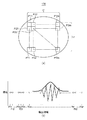
図1(a)は、本発明の一側面としての計測装置100の構成を示す概略図である。計測装置100は、計測対象物の被計測面103の高さを計測する計測装置である。被計測面103は、計測対象物の表面や内部の層面を含む。計測装置100は、低コヒーレント光源101から射出された光を、ハーフミラー(第1の光学系)104によって、参照光生成部102に向かう光(第1の光)と被計測面103に向かう光(第2の光)とに分離する。次いで、計測装置100は、参照光生成部102で生成された参照光と被計測面103で反射された光(計測光)とを干渉させ、かかる干渉光の強度を検出部108で検出する。そして、処理部(コンピュータ)111は、検出部108で検出された干渉光の強度(検出信号)のデータを取得し、そのデータを用いて被計測面103の高さを算出する。
FIG. 1A is a schematic diagram showing a configuration of a
計測装置100の構成及び被計測面103の高さを計測するための処理について詳細に説明する。計測装置100は、ハーフミラー104で分離された2つの光のうち一方の光(第1の光)を参照光生成部102に平行光(略平行光)で入射させるための光学系105を、低コヒーレント光源101と参照光生成部102との間の光路に有する。図1(a)では、光学系105は、1つのレンズで構成されているが、複数のレンズや複数のミラーなどで構成されていてもよい。また、図1(a)では、低コヒーレント光源101とハーフミラー104との間の光路に1つの光学系105が配置されている。但し、参照光生成部102に平行光を入射させるために、複数の光学系105を低コヒーレント光源101と参照光生成部102との間の光路に配置してもよい。
The configuration for measuring
参照光生成部102は、光路長差発生部201を含み、入射した平行光の光から、かかる光の伝播方向に垂直な断面において、2次元状の光路長差を有する複数の参照光束を含む参照光を生成する。参照光生成部102の構成については、後で詳細に説明する。
The reference
検出部108は、参照光と計測光との干渉光の強度を検出する複数の領域(検出領域)、例えば、CCD又はMOS素子(光電変換素子)を2次元状に配列した2次元CCDセンサや2次元CMOSセンサで構成されている。但し、検出部108は、2次元CCDセンサや2次元CMOSセンサに限定されるものではなく、光電変換素子を1次元状に配列した1次元CCDセンサや1次元CMOSセンサを複数個配置して2次元センサを構成してもよい。
The
光学系(第2の光学系)109は、参照光生成部102で生成された参照光を、主波長の光が平行光となるように検出部108に入射させる。換言すれば、光学系109は、参照光生成部102で生成された参照光の複数の参照光束のそれぞれが対応する複数の検出領域のそれぞれに入射するように、参照光を検出部108に入射させる。なお、主波長の光とは、低コヒーレント光源101から射出される複数の波長の光のうち任意の波長の光(例えば、複数の波長の光うち最もエネルギー強度が高い波長の光)を表す。図1(a)では、光学系109は、ミラー及びハーフミラーで構成されているが、レンズやその他の光学素子を含んでいてもよい。
The optical system (second optical system) 109 causes the reference light generated by the reference
参照光生成部102(光路長差発生部201)と検出部108との間の光路には、参照光生成部102で参照光を生成する際に生じる色分散のうち、主波長に対する色分散を低減するための光学系(第5の光学系)110が配置されている。図1(a)では、光学系110は、1つのレンズで構成されているが、主波長に対する色分散を低減するために、複数のレンズや複数のミラーなどで構成されていてもよい。なお、色分散には回転対称性を有さない成分が含まれるため、光学系110は、回転対称軸を有さない非回転対称形状の光学面を有する非回転対称光学素子を少なくとも1つ含むとよい。
In the optical path between the reference light generation unit 102 (optical path length difference generation unit 201) and the
光学系(第3の光学系)106は、ハーフミラー104で分離された2つの光のうち他方の光(第2の光)を被計測面103の計測点に集光する。図1(a)では、光学系106は、1つのレンズで構成されているが、光を被計測面103の計測点に集光するために、複数のレンズや複数のミラーなどで構成されていてもよい。また、光学系106は、焦点位置を変化させる焦点位置可変機構や焦点位置を最適な位置に自動で変更するオートフォーカス機構を含んでもよい。
The optical system (third optical system) 106 condenses the other light (second light) of the two lights separated by the
光学系(第4の光学系)107は、被計測面103の計測点で反射された光を検出部108に平行光(略平行光)で入射させる。換言すれば、光学系109は、被計測面103の計測点で反射された光が検出部108の複数の検出領域のそれぞれに入射するように、被計測面103の計測点で反射された光を計測光として検出部108に入射させる。図1(a)では、光学系107は、1つのレンズで構成されているが、複数のレンズや複数のミラーなどで構成されていてもよい。また、図1(a)では、光学系106と光学系107とは、異なる光学系で構成されているが、図1(b)に示すように、1つの光学系112で構成してもよい。光学系112は、光学系106の機能と光学系107の機能とを有する。
The optical system (fourth optical system) 107 causes the light reflected at the measurement point of the
計測装置100において、被計測面103の計測点で反射された光のうち検出部108の複数の検出領域のそれぞれに入射する光(計測光)は、計測点から略等しい光路長で(即ち、光路長差がなく)検出部108(の検出領域)に入射する。一方、参照光に含まれる複数の参照光束のそれぞれは、検出部108の対応する複数の領域のそれぞれに入射し、その光路長は、検出部108(の検出領域)において2次元状の分布を有する。また、参照光においては、光学系110によって主波長に対する色分散が低減されているため、主波長以外の波長の光の光路長は、検出部108(の検出領域)において主波長の光路長と略等しい2次元状の分布を有する。従って、検出部108の各検出領域では、それぞれ異なる光路長を有する参照光束とそれぞれ略等しい光路長を有する計測光との干渉光の強度が検出される。
In the measuring
検出部108で検出される干渉光の強度は、参照光束の光路長と計測光の光路長とが一致した場合に最大値となり、参照光束の光路長と計測光の光路長との差(光路長差)が大きくなるにつれて減衰振動する。従って、処理部111は、干渉光の強度が最大値となる参照光束の光路長を求めることによって、被計測面103の計測点までの高さ(高さ情報)を得ることができる。但し、実際には、減衰振動が最大値となる参照光束の光路長を求めることは難しいため、処理部111は、幾つかの計測結果から減衰振動の包絡線を求め、かかる包絡線の頂点位置を最大値の位置として被計測面103の計測点の高さに変換している。
The intensity of the interference light detected by the
減衰運動の包絡線を高精度に求めるためには、一般的に、参照光束の光路長を主波長λの1/8程度の間隔で変化させて干渉光の強度を検出する必要がある。ここで、特許文献1及び2や非特許文献1などの従来技術では、参照光束の光路長差が1次元状の分布となっている。従って、かかる参照光束が入射する検出部の検出領域(画素)の数をm個とし、各検出領域のそれぞれに光路長がdだけ異なる参照光束が入射するとすれば、検出部で検出可能な高さの範囲は、以下の式1で表される。
In order to obtain the envelope of the damped motion with high accuracy, it is generally necessary to detect the intensity of the interference light by changing the optical path length of the reference light beam at intervals of about 1/8 of the main wavelength λ. Here, in the prior arts such as
d×m ・・・(式1)
従って、従来技術では、計測可能な被計測面の高さの範囲(計測範囲)も式1で表される範囲に限定されてしまう。例えば、dをλ/8とした場合、被計測面(の計測点)が計測装置の基準位置からm×λ/8の範囲内に存在しないと、被計測面の高さを計測することができない。また、計測範囲を拡大するためにdを大きな値にした場合、被計測面の高さを高精度に計測することができない。
d × m (Formula 1)
Therefore, in the prior art, the range (measurement range) of the height of the surface to be measured that can be measured is also limited to the range represented by
一方、本実施形態における計測装置100では、上述したように、参照光束の光路長差が2次元状の分布となっている。従って、かかる参照光束が入射する検出部108の検出領域(画素)の数はm×n個となり、検出部108で検出可能な高さの範囲は、以下の式2で表される。
On the other hand, in the
d×m×n ・・・(式2)
例えば、検出部108の各検出領域P11乃至Pnmの一例を図2(a)に示す。図2(a)を参照するに、参照光束のそれぞれが入射する検出部108の検出領域はm×n個であり、各検出領域P11乃至Pnmに入射する参照光束の光路長はdだけ異なっている。従って、計測装置100は、従来技術と比較して、計測可能な被計測面103の高さの範囲(計測範囲)を約n倍としながらも、被計測面103の高さを高精度に計測することができる。
d × m × n (Formula 2)
For example, an example of each detection region P11 to Pnm of the
図2(b)は、検出部108の各検出領域P11乃至Pnmと、各検出領域P11乃至Pnmで検出された干渉光の強度との関係を示す図である。ここでは、検出領域P11に入射する参照光束の光路長が最も短く、検出領域P12、P13、・・・、P1m、P21、P22、・・・、P2m、・・・、Pn1、Pn2、・・・、Pnmの順に、入射する参照光束の光路長がdだけ長くなるものとする。図2(b)では、検出部108で検出された干渉光の強度を、参照光束の光路長が短い順にプロットしている。従って、図2(b)における横軸は、参照光束の光路長に変換することが可能である。検出部108で検出された干渉光の強度から被計測面103(の計測点)の高さを求めるためには、上述したように、図2(b)に太線で示す包絡線を演算などによって求める。そして、かかる包絡線の最大値の位置に相当する参照光束の光路長を求めることで、被計測面103の高さを得ることができる。換言すれば、処理部111において、検出部108の複数の検出領域のそれぞれに入射する複数の参照光束のそれぞれが有する光路長と複数の検出領域との対応関係に基づいて、検出部108で検出される干渉光の強度から計測点における高さを算出すればよい。
FIG. 2B is a diagram illustrating a relationship between the detection regions P11 to Pnm of the
従来技術では、検出部の一方向に配列された検出領域、例えば、検出領域P11乃至P1mのみで干渉光の強度(被計測面の高さに関する情報)を検出しているため、m個の干渉光の強度しか得ることができない。従って、図2(b)では、検出領域P11乃至P1mで検出された干渉光の強度からは減衰振動が得られず、包絡線を求めることができない。換言すれば、従来技術では、被計測面の高さを求めることができない。一方、本実施形態における計測装置100では、検出部108の検出領域P11乃至Pnmで干渉光の強度を検出しているため、m×n個の干渉光の強度を得ることができ、計測範囲の広範囲化を実現している。
In the conventional technique, since the intensity of interference light (information on the height of the surface to be measured) is detected only in the detection areas arranged in one direction of the detection unit, for example, the detection areas P11 to P1m, m interferences are detected. Only the intensity of light can be obtained. Accordingly, in FIG. 2B, no damped vibration is obtained from the intensity of the interference light detected in the detection regions P11 to P1m, and the envelope cannot be obtained. In other words, the prior art cannot determine the height of the surface to be measured. On the other hand, in the
また、従来技術では、式1で表される範囲外に被計測面が存在する場合には、参照光を生成する参照面を駆動して参照光の光路長を変更する、或いは、検出部と被計測面との間の相対的な距離を変更する必要が生じてしまう。従って、参照面を駆動する時間などが必要となるため、被計測面の高さを短時間で計測することができなくなる。一方、本実施形態における計測装置100では、上述したように、従来技術と比較して、計測可能な被計測面103の高さの範囲が約n倍となっているため、上述したような駆動を必要とすることなく、被計測面103の高さを短時間で計測することができる。
Further, in the related art, when the measurement target surface is outside the range represented by
本実施形態では、検出部108の各検出領域P11乃至Pnmに、それぞれdだけ光路長が異なる参照光束が入射する構成について説明したが、これに限定されるものではない。例えば、検出部108の各検出領域P11乃至Pnmに入射する参照光束の一部の光路長が重複していてもよい。この場合、検出部108で検出可能な高さの範囲は、式2で表される範囲から光路長の重複部を除いた範囲となる。
In the present embodiment, the configuration in which the reference light beams having different optical path lengths by d are respectively incident on the detection regions P11 to Pnm of the
次に、参照光生成部102の構成について説明する。参照光生成部102は、上述したように、参照光束に2次元状の光路長差を発生させる光路長差発生部201を含んでいる。図3(a)及び図3(b)は、参照光生成部102の構成の一例を模式的に示す図である。
Next, the configuration of the reference
図3(a)を参照するに、ハーフミラー104で分離された2つの光のうち参照光生成部102に入射する光は、参照光生成部102に含まれる光路長差発生部201の入射口210に入射し、光路長差発生部201の射出口211から射出される。光路長差発生部201の射出口211から射出された光は、光学系202を介して、参照光生成部102から射出される。光学系202は、参照光生成部102から射出される光の方向(射出方向)を選択するために配置されている。図3(a)では、光学系202は、1つのミラーで構成されているが、複数のレンズや複数のミラーなどで構成されていてもよい。また、図1(a)では、光学系110は、参照光生成部102と光学系109との間の光路に配置されている。但し、光学系110は、光路長差発生部201と検出部108との間の光路に配置されていればよく、例えば、図3(a)に示すように、参照光生成部102に含まれていてもよい。
Referring to FIG. 3A, the light incident on the reference
また、式2で表される計測範囲を更に広範囲化したい場合には、参照光生成部102の構成を図3(b)に示す構成にすればよい。図3(b)に示す参照光生成部102は、図3(a)に示す構成に加えて、光学系203と、光学系203を駆動する駆動部(不図示)とを有する。図3(b)に示す参照光生成部102においては、駆動部によって光学系203を駆動することで検出部108までの光路長を変更する(例えば、長くする)ことが可能となり、計測範囲の更なる広範囲化を実現することができる。図3(b)では、光学系203は、2つのミラーで構成されているが、検出部108までの光路長を変更するために、レンズやその他の光学素子を含んでいてもよい。
Further, in order to further widen the measurement range represented by Expression 2, the configuration of the reference
また、図3(b)に示す参照光生成部102において、d(光路長差)を波長以上の値に設定し、駆動部による光学系203の駆動量の刻み(単位駆動量)を波長以下に設定することによって、計測範囲の更なる広範囲化を実現することも可能である。
Further, in the reference
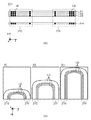
図4(a)及び図4(b)は、光路長差発生部201の構成の一例を模式的に示す図である。光路長差発生部201は、入射口210を形成する入射窓IWと射出口211を形成する射出窓EWとの間の距離(即ち、長さ)が互いに異なる複数の光導波路LGを含む。また、複数の光導波路LGは、例えば、光ファイバで構成され、それぞれの射出口EWが第1の方向(例えば、y軸方向)及び第1の方向に直交する第2の方向(例えば、z軸方向)に沿うように、2次元状に配列される。具体的には、光路長差発生部201は、図4(a)に示すように、入射窓IW及び射出窓EWをy軸方向に沿って一列に配列させた光導波路LGを含む複数の層A1乃至AHを、z軸方向に積層して構成されている。また、図4(b)に示すように、層A1に含まれる複数の光導波路LGのそれぞれの入射窓IWと射出窓EWとの間の距離は、互いにdだけ異なる。同様に、層A2乃至AHのそれぞれに含まれる光導波路LGのそれぞれの入射窓IWと射出窓EWとの間の距離は、互いにdだけ異なる。なお、各層A1乃至AHのそれぞれに含まれる光導波路LGのそれぞれの入射窓IWと射出窓EWとの間の距離は重複しないことが好ましいが、製造難易度などの観点から重複があってもよい。
4A and 4B are diagrams schematically illustrating an example of the configuration of the optical path length
図4(a)及び図4(b)を参照するに、光路長差発生部201の入射口210から入射した光は、2次元状に配列された互いに異なる長さの光導波路LGを通過する。従って、光路長差発生部201の射出口211から射出される光は、2次元状の光路長差を有することになる。
Referring to FIGS. 4A and 4B, light incident from the
図5(a)及び図5(b)は、参照光生成部102の別の構成の一例を模式的に示す図である。参照光生成部102は、図5(a)及び図5(b)に示すように、光路長差発生部201として、第1の光路長差発生部201Aと、第2の光路長差発生部201Bとを含んでいる。第1の光路長差発生部201A及び第2の光路長差発生部201Bのそれぞれは、後述するように、少なくとも1つの回折光学素子を含む。
FIG. 5A and FIG. 5B are diagrams schematically illustrating an example of another configuration of the reference
図5(a)を参照するに、ハーフミラー104で分離された2つの光のうち参照光生成部102に入射する光は、第1の光路長差発生部201Aの入射口210に入射し、第1の光路長差発生部201Aの射出口212から射出される。また、第1の光路長差発生部201Aの射出口212から射出された光は、第2の光路長差発生部201Bの入射口213に入射し、第2の光路長差発生部201Bの射出口211から射出される。第2の光路長差発生部201Bの射出口211から射出された光は、光学系202を介して、参照光生成部102から射出される。
Referring to FIG. 5A, the light that enters the reference
また、式2で表される計測範囲を更に広範囲化したい場合には、参照光生成部102の構成を図5(b)に示す構成にすればよい。図5(b)に示す参照光生成部102は、図5(a)に示す構成に加えて、光学系203と、光学系203を駆動する駆動部(不図示)とを有する。図5(b)に示す参照光生成部102においては、上述したように、駆動部によって光学系203を駆動することで検出部108までの光路長を変更する(例えば、長くする)ことが可能となり、計測範囲の更なる広範囲化を実現することができる。
Further, in order to further widen the measurement range represented by Equation 2, the configuration of the reference
また、図5(b)に示す参照光生成部102において、d(光路長差)を波長以上の値に設定し、駆動部による光学系203の駆動量の刻み(単位駆動量)を波長以下に設定することによって、計測範囲の更なる広範囲化を実現することも可能である。
Further, in the reference
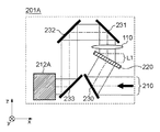
図6は、第1の光路長差発生部201Aの構成を模式的に示す図である。図6を参照するに、入射口210から入射した光は、ミラー230で偏向されて第1の回折光学素子220に入射し、第1の回折光学素子220で回折される。第1の回折光学素子220で回折された光は、光学系110を介して、ミラー231、232及び233で偏向される。ミラー233で偏向された光は、y軸方向に光を偏向するミラー212Aを介して、射出口212から射出される。なお、図6では、第1の光路長差発生部201Aは、1つの回折光学素子(第1の回折光学素子220)を含む構成であるが、複数の回折光学素子を含む構成であってもよい。また、ミラー212A、230乃至233は、図6に示す構成に限定されるものではなく、入射口210から入射した光が第1の回折光学素子220を通過して射出口212に導光される構成であればよい。また、図1(a)では、光学系110は、参照光生成部102と光学系109との間の光路に配置されている。但し、光学系110は、第1の光路長差発生部201Aと検出部108との間の光路に配置されていればよく、例えば、図6に示すように、第1の光路長差発生部201Aに含まれていてもよい。なお、色分散は第1の回折光学素子220において発生するため、図6に示すように、光の伝播方向に沿って、第1の回折光学素子220に隣接して配置するとよい。
FIG. 6 is a diagram schematically illustrating a configuration of the first optical path length
第1の回折光学素子220は、図7(a)及び図7(b)に示すように、光を回折するための(即ち、回折光を発生させるための)繰り返しパターンをxy平面上に有する。図7(a)及び図7(b)は、第1の回折光学素子220の構成の一例を模式的に示す図である。図7(a)は、第1の回折光学素子220のxy平面への投影図であり、図7(b)は、第1の回折光学素子220のxz平面への投影図である。
As shown in FIGS. 7A and 7B, the first diffractive
第1の回折光学素子220においては、x軸方向(第1の方向)に繰り返しパターンが形成されている。以下では、繰り返しパターンが形成される方向を繰り返し方向と称する。また、第1の回折光学素子220において、繰り返しパターンは、主波長に対して任意の回折光を選択的に発生させる形状を有する。
In the first diffractive
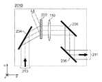
図7は、第2の光路長差発生部201Bの構成を模式的に示す図である。第1の光路長差発生部201Aの射出口212から射出された光は、第2の光路長差発生部201Bの入射口213に入射し、ミラー234で偏向される。ミラー234で偏向された光は、第2の回折光学素子222で回折され、光学系110を介して、ミラー235及び236で偏向され、射出口211から射出される。なお、図7では、第2の光路長差発生部201Bは、1つの回折光学素子(第2の回折光学素子222)を含む構成であるが、複数の回折光学素子を含む構成であってもよい。また、ミラー234乃至236は、図8に示す構成に限定されるものではなく、入射口213から入射した光が第2の回折光学素子222を通過して射出口211に導光される構成であればよい。また、図1(a)では、光学系110は、参照光生成部102と光学系109との間の光路に配置されている。但し、光学系110は、第2の光路長差発生部201Bと検出部108との間の光路に配置されていればよく、例えば、図8に示すように、第2の光路長差発生部201Bに含まれていてもよい。なお、色分散は第2の回折光学素子222において発生するため、図8に示すように、光の伝播方向に沿って、第2の回折光学素子222に隣接して配置するとよい。
FIG. 7 is a diagram schematically illustrating the configuration of the second optical path length
第2の回折光学素子222においては、y軸方向(第2の方向)に光を回折するための(即ち、回折光を発生させるための)繰り返しパターンが形成されている。また、第2の光路長差発生部201Bにおいて、第2の回折光学素子222は、第2の回折光学素子222の繰り返し方向が第1の回折光学素子220の繰り返し方向に直交するように、配置される。従って、第1の光路長差発生部201Aでは、第1の回折光学素子220の繰り返し方向に分布を有する光路長差が発生し、第2の光路長差発生部201Bでは、第2の回折光学素子222の繰り返し方向に分布を有する光路長差が発生する。
In the second diffractive
ここで、図6を参照して、第1の光路長差発生部201Aを幾何学的に説明する。第1の光路長差発生部201Aでは、第1の回折光学素子220の繰り返し方向がxz平面内に存在することによって、入射光はxz平面内において最大で距離L1だけ異なる光路を通過する。従って、第1の回折光学素子220で回折された光には、繰り返し方向に対して最大で距離L1の光路長差が生じている。
Here, with reference to FIG. 6, the first optical path length
同様に、図8を参照して、第2の光路長差発生部201Bを幾何学的に説明する。第2の光路長差発生部201Bでは、第2の回折光学素子222の繰り返し方向がy軸内に存在することによって、入射光はxy平面内において最大で距離L3だけ異なる光路を通過する。従って、第2の回折光学素子222で回折された光には、繰り返し方向に対して最大で距離L3の光路長差が生じている。
Similarly, the second optical path length
このように、第1の光路長差発生部201Aと第2の光路長差発生部201Bとは、互いに異なる2つの方向に分布を有する光路長を発生させる。換言すれば、第1の回折光学素子220の繰り返し方向と第2の回折光学素子222の繰り返し方向とを直交させることによって、第1の光路長差発生部201Aと第2の光路長差発生部201Bとでは、互いに直交する2方向に分布を有する光路長が発生する。従って、第2の光路長差発生部201Bの射出口211から射出された光は、2次元状の光路長差を有することになる。
Thus, the first optical path length
なお、図6及び図8では、第1の光路長差発生部201A及び第2の光路長差発生部201Bは、透過型の回折光学素子を有しているが、これに限定されるものではない。例えば、図9及び図10に示すように、第1の光路長差発生部201A及び第2の光路長差発生部201Bは、反射型の回折光学素子を有していてもよい。図9は、第1の光路長差発生部201Aの別の構成を模式的に示す図である。図10は、第2の光路長差発生部201Bの別の構成を模式的に示す図である。
In FIGS. 6 and 8, the first optical path length
図9に示す第1の光路長差発生部201Aは、透過型の第1の回折光学素子220の代わりに反射型の第1の回折光学素子221を有する。また、図10に示す第2の光路長差発生部201Bは、透過型の第2の回折光学素子222の代わりに反射型の第2の回折光学素子223を有する。第1の回折光学素子221の繰り返し方向はxz平面内に存在し、第2の回折光学素子223の繰り返し方向はxy平面内に存在する。
A first optical path length
図9を参照して、第1の光路長差発生部201Aを幾何学的に説明する。第1の光路長差発生部201Aでは、第1の回折光学素子221の繰り返し方向がxz平面内に存在することによって、第1の回折光学素子221で回折された光には、繰り返し方向に対して最大で距離L2の光路長差が生じている。
With reference to FIG. 9, the first optical path length
同様に、図10を参照して、第2の光路長差発生部201Bを幾何学的に説明する。第2の光路長差発生部201Bでは、第2の回折光学素子223の繰り返し方向がxy平面内に存在することによって、第2の回折光学素子223で回折された光には、繰り返し方向に対して最大で距離L4の光路長差が生じている。
Similarly, the second optical path length
従って、第1の回折光学素子221の繰り返し方向と第2の回折光学素子223の繰り返し方向とを直交させることによって、第1の光路長差発生部201Aと第2の光路長差発生部201Bとでは、互いに直交する2方向に分布を有する光路長が発生する。従って、第2の光路長差発生部201Bの射出口211から射出された光は、2次元状の光路長差を有することになる。
Therefore, by making the repetition direction of the first diffractive
このように、図6又は図9に示す第1の光路長差発生部201Aと、図8又は図10に示す第2の光路長差発生部201Bとを適当に組み合わせることによって、2次元状の光路長差を有する光を生成することができる。
As described above, by appropriately combining the first optical path length
図11は、光路長差発生部201の別の構成の一例を模式的に示す図である。図11に示す光路長差発生部201は、後述するように、少なくとも1つの回折光学素子を含む。
FIG. 11 is a diagram schematically illustrating an example of another configuration of the optical path length
図11を参照するに、入射口210から入射した光は、回折光学素子224で回折され、光学系110を介して、ミラー236及び237で偏向され、射出口211から射出される。なお、ミラー236及び237は、図11に示す構成に限定されるものではなく、入射口210から入射した光が回折光学素子224を通過して射出口211に導光される構成であればよい。また、図1(a)では、光学系110は、参照光生成部102と光学系109との間の光路に配置されている。但し、光学系110は、第1の光路長差発生部201と検出部108との間の光路に配置されていればよく、例えば、図10に示すように、光路長差発生部201に含まれていてもよい。なお、色分散は回折光学素子224において発生するため、図10に示すように、光の伝播方向に沿って、回折光学素子224に隣接して配置するとよい。また、回折光学素子224では、後述するように、異なる2つの方向に対して色分散が発生するため、図10に示すように、光学系110は、少なくとも2つの光学素子を含むとよい。
Referring to FIG. 11, light incident from the
回折光学素子224は、図12(a)乃至図12(c)に示すように、光を回折するための繰り返しパターンを互いに直交する2つの方向に有する。図12(a)乃至図12(c)は、回折光学素子224の構成の一例を模式的に示す図である。図12(a)は、回折光学素子224のxy平面への投影図であり、図12(b)は、回折光学素子224のxz平面への投影図であり、図12(c)は、回折光学素子224の斜視図である。
As shown in FIGS. 12A to 12C, the diffractive
回折光学素子224の2つの繰り返し方向のうち、一方の繰り返し方向は、図12(a)に矢印で示すようにxy平面内に存在し、他方の繰り返し方向は、図12(b)に矢印で示すようにxz平面内に存在する。このように、回折光学素子224は、互いに直交する2つの方向に繰り返し方向を有するため、回折光学素子224で回折された光は、2次元状の光路長差を有する。具体的には、回折光学素子224に入射した光は、段差構造c11乃至cnmを通過する。ここで、段差構造c11乃至cnmは、空気の屈折率とは異なる屈折率を有し、光の伝播方向にそれぞれに異なる長さを有する。従って、段差構造c11乃至cnmのそれぞれを通過した光は、異なる光路長を有する。換言すれば、回折光学素子224で回折された光には、段差構造c11乃至cnmの配置に応じて、2次元状の光路長差が生じる。
Of the two repeating directions of the diffractive
なお、図11では、光路長差発生部201は、透過型の回折光学素子を有しているが、これに限定されるものではない。例えば、図13に示すように、光路長差発生部201は、反射型の回折光学素子を有していてもよい。図13は、光路長差発生部201の別の構成を模式的に示す図である。
In FIG. 11, the optical path length
図13に示す光路長差発生部201は、透過型の回折光学素子224の代わりに反射型の回折光学素子225を有する。回折光学素子225は、回折光学素子224と同様に、図12(a)乃至図12(c)に示される段差構造をy軸に対して反転させた段差構造を有し、その表面には光を反射する反射面が形成されている。従って、回折光学素子225に入射した光は、段差構造c11乃至cnmの反射面で反射される。ここで、段差構造c11乃至cnmの反射面は、光の伝播方向に対して、それぞれ異なる位置に存在しているため、回折光学素子225で反射された光には、段差構造c11乃至cnmの配置に応じて、2次元状の光路長差が生じる。
The optical path length
なお、図11及び図13では、光路長差発生部201は、1つの回折光学素子(透過型の回折光学素子224又は反射型の回折光学素子225)を含む構成であるが、複数の回折光学素子を含む構成であってもよい。
11 and 13, the optical path length
以上、本発明の好ましい実施形態について説明したが、本発明はこれらの実施形態に限定されないことはいうまでもなく、その要旨の範囲内で種々の変形及び変更が可能である。 As mentioned above, although preferable embodiment of this invention was described, it cannot be overemphasized that this invention is not limited to these embodiment, A various deformation | transformation and change are possible within the range of the summary.
Claims (8)
参照光と計測光との干渉光の強度を検出する複数の領域が2次元状に配列された検出部と、
光源からの光を第1の光と第2の光とに分離する第1の光学系と、
前記第1の光が入射され、前記第1の光から、断面内の互いに垂直な2方向の各々において光路長差を有する複数の参照光束を含む前記参照光を生成する生成部と、
前記生成部で生成された前記複数の参照光束のそれぞれが対応する前記複数の領域のそれぞれに入射するように、前記参照光を前記検出部に入射させる第2の光学系と、
前記第2の光を前記被計測面の計測点に集光する第3の光学系と、
前記計測点で反射された前記第2の光が前記複数の領域のそれぞれに入射するように、前記第2の光を前記計測光として前記検出部に入射させる第4の光学系と、
前記複数の領域のそれぞれで検出される干渉光の強度から前記計測点における前記被計測面の高さを算出する処理部と、
を有し、
前記生成部は、前記第1の光が入射する入射口と前記第1の光が射出する射出口との間の距離が互いに異なる複数の光導波路を含み、
前記複数の光導波路は、前記複数の光導波路のそれぞれの前記射出口が第1の方向及び前記第1の方向と直交する第2の方向に沿うように、配列されていることを特徴とする計測装置。 A measuring device for measuring the height of a surface to be measured,
A detection unit in which a plurality of regions for detecting the intensity of interference light between the reference light and the measurement light are two-dimensionally arranged;
A first optical system that separates light from the light source into first light and second light;
A generator that receives the first light and generates the reference light including a plurality of reference light fluxes having optical path length differences in each of two directions perpendicular to each other in the cross section from the first light;
A second optical system that causes the reference light to enter the detection unit such that each of the plurality of reference light fluxes generated by the generation unit is incident on each of the corresponding regions;
A third optical system for condensing the second light at a measurement point on the surface to be measured;
A fourth optical system that causes the second light to be incident on the detection unit as the measurement light so that the second light reflected at the measurement point is incident on each of the plurality of regions;
A processing unit that calculates the height of the measurement surface at the measurement point from the intensity of interference light detected in each of the plurality of regions;
Have
The generating unit includes a plurality of optical waveguides having different distances between an entrance through which the first light enters and an exit through which the first light exits,
The plurality of optical waveguides are arranged such that each of the exit ports of the plurality of optical waveguides is along a first direction and a second direction orthogonal to the first direction. that a total of measuring apparatus.
参照光と計測光との干渉光の強度を検出する複数の領域が2次元状に配列された検出部と、
光源からの光を第1の光と第2の光とに分離する第1の光学系と、
前記第1の光が入射され、前記第1の光から、断面内の互いに垂直な2方向の各々において光路長差を有する複数の参照光束を含む前記参照光を生成する生成部と、
前記生成部で生成された前記複数の参照光束のそれぞれが対応する前記複数の領域のそれぞれに入射するように、前記参照光を前記検出部に入射させる第2の光学系と、
前記第2の光を前記被計測面の計測点に集光する第3の光学系と、
前記計測点で反射された前記第2の光が前記複数の領域のそれぞれに入射するように、前記第2の光を前記計測光として前記検出部に入射させる第4の光学系と、
前記複数の領域のそれぞれで検出される干渉光の強度から前記計測点における前記被計測面の高さを算出する処理部と、
を有し、
前記生成部は、光を回折するための繰り返しパターンを第1の方向に有する第1の回折光学素子と、光を回折するための繰り返しパターンを第2の方向に有する第2の回折光学素子とを含み、
前記第1の回折光学素子及び前記第2の回折光学素子は、前記第1の方向と前記第2の方向とが直交するように配置され、
前記第1の回折光学素子の繰り返しパターンで回折された前記第1の光は前記第1の方向に光路長差を有し、前記第2の回折光学素子の繰り返しパターンで回折された前記第1の光は前記第2の方向に光路長差を有することを特徴とする計測装置。 A measuring device for measuring the height of a surface to be measured,
A detection unit in which a plurality of regions for detecting the intensity of interference light between the reference light and the measurement light are two-dimensionally arranged;
A first optical system that separates light from the light source into first light and second light;
A generator that receives the first light and generates the reference light including a plurality of reference light fluxes having optical path length differences in each of two directions perpendicular to each other in the cross section from the first light;
A second optical system that causes the reference light to enter the detection unit such that each of the plurality of reference light fluxes generated by the generation unit is incident on each of the corresponding regions;
A third optical system for condensing the second light at a measurement point on the surface to be measured;
A fourth optical system that causes the second light to be incident on the detection unit as the measurement light so that the second light reflected at the measurement point is incident on each of the plurality of regions;
A processing unit that calculates the height of the measurement surface at the measurement point from the intensity of interference light detected in each of the plurality of regions;
Have
The generating unit includes a first diffractive optical element having a repetitive pattern for diffracting light in a first direction, and a second diffractive optical element having a repetitive pattern for diffracting light in a second direction; Including
The first diffractive optical element and the second diffractive optical element are arranged so that the first direction and the second direction are orthogonal to each other,
The first light diffracted by the repeating pattern of the first diffractive optical element has an optical path length difference in the first direction, and the first light diffracted by the repeating pattern of the second diffractive optical element. the light meter measuring device you characterized by having an optical path length difference in the second direction.
参照光と計測光との干渉光の強度を検出する複数の領域が2次元状に配列された検出部と、
光源からの光を第1の光と第2の光とに分離する第1の光学系と、
前記第1の光が入射され、前記第1の光から、断面内の互いに垂直な2方向の各々において光路長差を有する複数の参照光束を含む前記参照光を生成する生成部と、
前記生成部で生成された前記複数の参照光束のそれぞれが対応する前記複数の領域のそれぞれに入射するように、前記参照光を前記検出部に入射させる第2の光学系と、
前記第2の光を前記被計測面の計測点に集光する第3の光学系と、
前記計測点で反射された前記第2の光が前記複数の領域のそれぞれに入射するように、前記第2の光を前記計測光として前記検出部に入射させる第4の光学系と、
前記複数の領域のそれぞれで検出される干渉光の強度から前記計測点における前記被計測面の高さを算出する処理部と、
を有し、
前記生成部は、光を回折するための繰り返しパターンを第1の方向及び前記第1の方向と直交する第2の方向に有する回折光学素子を含み、
前記回折光学素子の繰り返しパターンで回折された前記第1の光は、前記第1の方向及び前記第2の方向のそれぞれに光路長差を有することを特徴とする計測装置。 A measuring device for measuring the height of a surface to be measured,
A detection unit in which a plurality of regions for detecting the intensity of interference light between the reference light and the measurement light are two-dimensionally arranged;
A first optical system that separates light from the light source into first light and second light;
A generator that receives the first light and generates the reference light including a plurality of reference light fluxes having optical path length differences in each of two directions perpendicular to each other in the cross section from the first light;
A second optical system that causes the reference light to enter the detection unit such that each of the plurality of reference light fluxes generated by the generation unit is incident on each of the corresponding regions;
A third optical system for condensing the second light at a measurement point on the surface to be measured;
A fourth optical system that causes the second light to be incident on the detection unit as the measurement light so that the second light reflected at the measurement point is incident on each of the plurality of regions;
A processing unit that calculates the height of the measurement surface at the measurement point from the intensity of interference light detected in each of the plurality of regions;
Have
The generation unit includes a diffractive optical element having a repetitive pattern for diffracting light in a first direction and a second direction orthogonal to the first direction,
Wherein said first light diffracted by the repeated pattern of the diffractive optical element, a total measuring device you characterized by having an optical path length difference in each of the first direction and the second direction.
参照光と計測光との干渉光の強度を検出する複数の領域が2次元状に配列された検出部と、
光源からの光を第1の光と第2の光とに分離する第1の光学系と、
前記第1の光が入射され、前記第1の光から、断面内の互いに垂直な2方向の各々において光路長差を有する複数の参照光束を含む前記参照光を生成する生成部と、
前記生成部で生成された前記複数の参照光束のそれぞれが対応する前記複数の領域のそれぞれに入射するように、前記参照光を前記検出部に入射させる第2の光学系と、
前記第2の光を前記被計測面の計測点に集光する第3の光学系と、
前記計測点で反射された前記第2の光が前記複数の領域のそれぞれに入射するように、前記第2の光を前記計測光として前記検出部に入射させる第4の光学系と、
前記複数の領域のそれぞれで検出される干渉光の強度から前記計測点における前記被計測面の高さを算出する処理部と、
前記生成部と前記検出部との間に配置され、前記生成部で前記参照光を生成する際に生じる色分散を低減する第5の光学系と、
を有することを特徴とする計測装置。 A measuring device for measuring the height of a surface to be measured,
A detection unit in which a plurality of regions for detecting the intensity of interference light between the reference light and the measurement light are two-dimensionally arranged;
A first optical system that separates light from the light source into first light and second light;
A generator that receives the first light and generates the reference light including a plurality of reference light fluxes having optical path length differences in each of two directions perpendicular to each other in the cross section from the first light;
A second optical system that causes the reference light to enter the detection unit such that each of the plurality of reference light fluxes generated by the generation unit is incident on each of the corresponding regions;
A third optical system for condensing the second light at a measurement point on the surface to be measured;
A fourth optical system that causes the second light to be incident on the detection unit as the measurement light so that the second light reflected at the measurement point is incident on each of the plurality of regions;
A processing unit that calculates the height of the measurement surface at the measurement point from the intensity of interference light detected in each of the plurality of regions;
A fifth optical system that is disposed between the generation unit and the detection unit and reduces chromatic dispersion generated when the generation unit generates the reference light ;
Total measuring apparatus shall be the features that you have a.
Priority Applications (2)
| Application Number | Priority Date | Filing Date | Title |
|---|---|---|---|
| JP2011103788A JP5743697B2 (en) | 2011-05-06 | 2011-05-06 | Measuring device |
| US13/459,962 US20120281233A1 (en) | 2011-05-06 | 2012-04-30 | Measurement apparatus |
Applications Claiming Priority (1)
| Application Number | Priority Date | Filing Date | Title |
|---|---|---|---|
| JP2011103788A JP5743697B2 (en) | 2011-05-06 | 2011-05-06 | Measuring device |
Publications (3)
| Publication Number | Publication Date |
|---|---|
| JP2012233828A JP2012233828A (en) | 2012-11-29 |
| JP2012233828A5 JP2012233828A5 (en) | 2014-06-05 |
| JP5743697B2 true JP5743697B2 (en) | 2015-07-01 |
Family
ID=47090033
Family Applications (1)
| Application Number | Title | Priority Date | Filing Date |
|---|---|---|---|
| JP2011103788A Expired - Fee Related JP5743697B2 (en) | 2011-05-06 | 2011-05-06 | Measuring device |
Country Status (2)
| Country | Link |
|---|---|
| US (1) | US20120281233A1 (en) |
| JP (1) | JP5743697B2 (en) |
Family Cites Families (11)
| Publication number | Priority date | Publication date | Assignee | Title |
|---|---|---|---|---|
| US6198540B1 (en) * | 1997-03-26 | 2001-03-06 | Kowa Company, Ltd. | Optical coherence tomography have plural reference beams of differing modulations |
| FR2783323B1 (en) * | 1998-09-10 | 2000-10-13 | Suisse Electronique Microtech | INTERFEROMETRIC DEVICE TO DETECT THE CHARACTERISTICS OF OPTICAL REFLECTION AND / OR TRANSMISSION IN DEPTH OF AN OBJECT |
| JP4464519B2 (en) * | 2000-03-21 | 2010-05-19 | オリンパス株式会社 | Optical imaging device |
| US7050171B1 (en) * | 2002-11-04 | 2006-05-23 | The United States Of America As Represneted By The Secretary Of The Army | Single-exposure interferometer with no moving parts |
| JP3889697B2 (en) * | 2002-11-22 | 2007-03-07 | 日本電信電話株式会社 | Optical bandpass filter |
| KR100578140B1 (en) * | 2004-10-07 | 2006-05-10 | 삼성전자주식회사 | Interferometer System For Measuring Displacement And Exposure System Using The Same |
| EP1812772A4 (en) * | 2004-11-18 | 2011-04-27 | Morgan Res Corp | Miniature fourier transform spectrophotometer |
| JP2006242570A (en) * | 2005-02-28 | 2006-09-14 | Fuji Xerox Co Ltd | Surface shape measuring apparatus |
| JP4987359B2 (en) * | 2006-06-13 | 2012-07-25 | 浜松ホトニクス株式会社 | Surface shape measuring device |
| DE102007010389B4 (en) * | 2007-03-03 | 2011-03-10 | Polytec Gmbh | Device for the optical measurement of an object |
| JP5663824B2 (en) * | 2008-03-18 | 2015-02-04 | 株式会社豊田中央研究所 | Distance measuring device |
-
2011
- 2011-05-06 JP JP2011103788A patent/JP5743697B2/en not_active Expired - Fee Related
-
2012
- 2012-04-30 US US13/459,962 patent/US20120281233A1/en not_active Abandoned
Also Published As
| Publication number | Publication date |
|---|---|
| JP2012233828A (en) | 2012-11-29 |
| US20120281233A1 (en) | 2012-11-08 |
Similar Documents
| Publication | Publication Date | Title |
|---|---|---|
| JP5966982B2 (en) | Confocal measuring device | |
| JP5882672B2 (en) | Optical position measuring device | |
| TWI658256B (en) | Confocal measuring device | |
| JPWO2014087726A1 (en) | Semiconductor laser device | |
| US8582110B2 (en) | Apparatus for low coherence optical imaging | |
| JP2009162539A (en) | Light wave interferometer apparatus | |
| JP2012181060A (en) | Spectral characteristic measuring apparatus and calibration method thereof | |
| JP2013224899A (en) | Surface shape measuring device and method | |
| JP5834979B2 (en) | Confocal measuring device | |
| JP5128364B2 (en) | Position measuring device | |
| JP5743697B2 (en) | Measuring device | |
| CN107532888B (en) | Interference fringe projection optical system and shape measuring device | |
| CN114341602B (en) | Spectrometry device | |
| JP2005221451A (en) | Laser displacement gauge | |
| WO2019031327A1 (en) | Optical apparatus | |
| JPWO2021044979A5 (en) | ||
| JP2012173125A (en) | Shape measuring apparatus and shape measuring method | |
| JP4027866B2 (en) | Position and orientation measurement method and position and orientation measurement apparatus | |
| JP2020020788A (en) | Optical encoder | |
| JP6371120B2 (en) | measuring device | |
| JP2006329673A (en) | Displacement measuring instrument | |
| JP2012181018A (en) | Movement information measuring device | |
| CN117629405A (en) | Spectrometer | |
| WO2020179068A1 (en) | Microscope | |
| JP2005249576A (en) | Interference measuring method and interferometer |
Legal Events
| Date | Code | Title | Description |
|---|---|---|---|
| A521 | Request for written amendment filed |
Free format text: JAPANESE INTERMEDIATE CODE: A523 Effective date: 20140417 |
|
| A621 | Written request for application examination |
Free format text: JAPANESE INTERMEDIATE CODE: A621 Effective date: 20140417 |
|
| A977 | Report on retrieval |
Free format text: JAPANESE INTERMEDIATE CODE: A971007 Effective date: 20150108 |
|
| A131 | Notification of reasons for refusal |
Free format text: JAPANESE INTERMEDIATE CODE: A131 Effective date: 20150116 |
|
| A521 | Request for written amendment filed |
Free format text: JAPANESE INTERMEDIATE CODE: A523 Effective date: 20150312 |
|
| TRDD | Decision of grant or rejection written | ||
| A01 | Written decision to grant a patent or to grant a registration (utility model) |
Free format text: JAPANESE INTERMEDIATE CODE: A01 Effective date: 20150330 |
|
| A61 | First payment of annual fees (during grant procedure) |
Free format text: JAPANESE INTERMEDIATE CODE: A61 Effective date: 20150428 |
|
| R151 | Written notification of patent or utility model registration |
Ref document number: 5743697 Country of ref document: JP Free format text: JAPANESE INTERMEDIATE CODE: R151 |
|
| LAPS | Cancellation because of no payment of annual fees |