EP0950148B1 - Method and device for controlling a drive unit of a vehicle - Google Patents
Method and device for controlling a drive unit of a vehicle Download PDFInfo
- Publication number
- EP0950148B1 EP0950148B1 EP98941245A EP98941245A EP0950148B1 EP 0950148 B1 EP0950148 B1 EP 0950148B1 EP 98941245 A EP98941245 A EP 98941245A EP 98941245 A EP98941245 A EP 98941245A EP 0950148 B1 EP0950148 B1 EP 0950148B1
- Authority
- EP
- European Patent Office
- Prior art keywords
- torque
- function
- drive unit
- driver
- maximum permitted
- Prior art date
- Legal status (The legal status is an assumption and is not a legal conclusion. Google has not performed a legal analysis and makes no representation as to the accuracy of the status listed.)
- Expired - Lifetime
Links
Images

Classifications
-
- F—MECHANICAL ENGINEERING; LIGHTING; HEATING; WEAPONS; BLASTING
- F02—COMBUSTION ENGINES; HOT-GAS OR COMBUSTION-PRODUCT ENGINE PLANTS
- F02D—CONTROLLING COMBUSTION ENGINES
- F02D41/00—Electrical control of supply of combustible mixture or its constituents
- F02D41/02—Circuit arrangements for generating control signals
- F02D41/14—Introducing closed-loop corrections
-
- F—MECHANICAL ENGINEERING; LIGHTING; HEATING; WEAPONS; BLASTING
- F02—COMBUSTION ENGINES; HOT-GAS OR COMBUSTION-PRODUCT ENGINE PLANTS
- F02D—CONTROLLING COMBUSTION ENGINES
- F02D31/00—Use of speed-sensing governors to control combustion engines, not otherwise provided for
- F02D31/001—Electric control of rotation speed
- F02D31/007—Electric control of rotation speed controlling fuel supply
- F02D31/009—Electric control of rotation speed controlling fuel supply for maximum speed control
-
- F—MECHANICAL ENGINEERING; LIGHTING; HEATING; WEAPONS; BLASTING
- F02—COMBUSTION ENGINES; HOT-GAS OR COMBUSTION-PRODUCT ENGINE PLANTS
- F02D—CONTROLLING COMBUSTION ENGINES
- F02D11/00—Arrangements for, or adaptations to, non-automatic engine control initiation means, e.g. operator initiated
- F02D11/06—Arrangements for, or adaptations to, non-automatic engine control initiation means, e.g. operator initiated characterised by non-mechanical control linkages, e.g. fluid control linkages or by control linkages with power drive or assistance
- F02D11/10—Arrangements for, or adaptations to, non-automatic engine control initiation means, e.g. operator initiated characterised by non-mechanical control linkages, e.g. fluid control linkages or by control linkages with power drive or assistance of the electric type
- F02D11/105—Arrangements for, or adaptations to, non-automatic engine control initiation means, e.g. operator initiated characterised by non-mechanical control linkages, e.g. fluid control linkages or by control linkages with power drive or assistance of the electric type characterised by the function converting demand to actuation, e.g. a map indicating relations between an accelerator pedal position and throttle valve opening or target engine torque
-
- F—MECHANICAL ENGINEERING; LIGHTING; HEATING; WEAPONS; BLASTING
- F02—COMBUSTION ENGINES; HOT-GAS OR COMBUSTION-PRODUCT ENGINE PLANTS
- F02D—CONTROLLING COMBUSTION ENGINES
- F02D2250/00—Engine control related to specific problems or objectives
- F02D2250/18—Control of the engine output torque
-
- F—MECHANICAL ENGINEERING; LIGHTING; HEATING; WEAPONS; BLASTING
- F02—COMBUSTION ENGINES; HOT-GAS OR COMBUSTION-PRODUCT ENGINE PLANTS
- F02D—CONTROLLING COMBUSTION ENGINES
- F02D2250/00—Engine control related to specific problems or objectives
- F02D2250/18—Control of the engine output torque
- F02D2250/26—Control of the engine output torque by applying a torque limit
-
- F—MECHANICAL ENGINEERING; LIGHTING; HEATING; WEAPONS; BLASTING
- F02—COMBUSTION ENGINES; HOT-GAS OR COMBUSTION-PRODUCT ENGINE PLANTS
- F02D—CONTROLLING COMBUSTION ENGINES
- F02D41/00—Electrical control of supply of combustible mixture or its constituents
- F02D41/02—Circuit arrangements for generating control signals
- F02D41/04—Introducing corrections for particular operating conditions
- F02D41/06—Introducing corrections for particular operating conditions for engine starting or warming up
Definitions
- the invention relates to a method and a device to control the drive unit of a motor vehicle according to the preambles of the independent claims.
- DE-A 195 36 038 describes a method and a device to control the drive unit of a motor vehicle known, in which a torque of the drive unit is dependent controlled by a setpoint for this torque becomes.
- a torque of the drive unit is dependent controlled by a setpoint for this torque becomes.
- a maximum permissible torque Drive unit formed, this with an actual Drive unit torque compared and fault response measures initiated when the actual torque the drive unit exceeds the maximum permissible torque.
- the maximum permissible torque depends on the target torque value educated. This in turn is based on the Position of a control element that can be actuated by the driver, for example of an accelerator pedal, or depending on that of others Control systems or functions predetermined target torque, for example depending on a target torque an engine drag torque control and / or an idle speed control calculated.
- the maximum allowable torque becomes dependent on the target torque value using a characteristic curve or a map is formed.
- a consideration of Tolerances of the drive unit, which e.g. through internal friction is not described. This is also permissible Moment depending on the driver's desired torque, so that at a theoretically conceivable error in the calculation of this Moments the permissible torque is also incorrect.
- Torque base Monitoring a control of a drive unit Torque base is significantly improved because the Formation of the maximum permissible torque, which of the monitoring underlying, tolerances are taken into account, too when external intervention works.
- driver's desired torque is not in the calculation of the permissible torque is received.
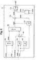
- FIG. 1 is a control device for a multi-cylinder Internal combustion engine 10 shown.
- the control device comprises an electronic control unit 12, which consists of at least a microcomputer 14, an input 16 and one Output unit 18 exists.
- Input unit 16, output unit 18 and the at least one microcomputer 14 are via one Communication bus 20 for mutual data exchange with one another connected.
- the input unit 16 are the input lines 22, 24, 28 and 30 fed.
- the line 22 comes a measuring device 32 for detecting the pedal position, the line 24 from a measuring device 34 for detection the engine speed, the line 28 from a measuring device 38 for detecting a motor load representative Size and line 30 of at least one other Control device 40, for example a control device for traction control for transmission control, for engine drag torque control, for driving speed control, etc.
- the quantity representing the engine load are air mass, air flow meter depending on the embodiment or pressure sensors to record the intake manifold pressure intended.
- the Control unit other sizes essential for engine control like engine temperature, driving speed, the time after Start, intake air temperature, etc.
- An output line 42 is connected to the output unit 18, on an electrically operated throttle valve 44, which is arranged in the air intake system 46 of the internal combustion engine is leads.
- the under the described by programs of the microcomputer realized engine control takes place through coordination the filling intervention (air intervention), the ignition angle setting and the change in fuel metering (Blanking of individual cylinders, displacement of the air / fuel composition) based on the torque the drive unit.
- the filling intervention air intervention
- the ignition angle setting and the change in fuel metering (Blanking of individual cylinders, displacement of the air / fuel composition) based on the torque the drive unit.
- a target torque Control of the drive unit selected This target torque is converted into a setpoint for the filling to be set, in an ignition angle and / or a fuel metering correction converted. In this way, the torque of the drive unit approximates the specified target torque.
- the maximum permissible torque When determining the maximum permissible torque, how shown below using the flow diagram according to FIG. 2, based on accelerator pedal position and engine speed from at least one map in which the essential Tolerances are taken into account, the maximum permissible Moment read. Furthermore, in a preferred embodiment another map is provided, which according to Start of the drive unit, especially when the drive unit is cold increased tolerances, for example as a result of Friction considered. This maximum allowable moment in Post-start also depends on the accelerator pedal position and Engine speed determined according to another map. This map is switched to if after Start certain conditions exist, for example the Temperature of the engine, the intake air temperature and / or the elapsed time after the start within specified value ranges lie.
- the maximum allowable moment determined in this way becomes for the above-mentioned torque monitoring and / or for limitation of the target torque.
- the maximum allowable The moment depends on the driver's request. Are functions active, which replace the driver's request or the torque versus that increases or decreases the driver's request maximum permissible moment, which in the above-mentioned way is formed, the actual situation of the controller not again. This is particularly important for interventions, which is the moment of the drive unit versus the driver's request increase, such as in a cruise control or an engine drag torque control.
- reliable torque monitoring (and / or limitation) too ensure is provided based on the driver's request formed maximum permissible moment with that of the to compare external interventions with the target torque.
- the larger of the two values is considered permissible Moment of monitoring and / or limitation supplied.
- an additional offset value is formed, that from a map depending on the resulting permissible torque and the engine speed is formed. This Offset value takes into account depending on the operating state different tolerance and leads to change in the resulting maximum permissible moments and therefore to be taken into account that depend on the operating condition of the engine Tolerance.
- the torque setpoints formed by external interventions such as engine drag torque control (mimsr) or a vehicle speed control (mifgr) and the moment of the drive unit compared to the driver's request a maximum value selection 100 fed.
- the target torque value for the external interventions is then in a maximum value selection 102 with that depending on the driver's request formed maximum permissible torque compared.
- the each larger of the two moment values is the resultant maximum permissible torque with torque monitoring fed.
- the maximum permissible depending on the driver's wishes Moment is either in a first map 104 or in determines a second map 106, depending on which operating state is present.
- the accelerator pedal position becomes the two maps wped and the engine speed nmot supplied.
- the maximum permissible torque is above the two maps stored these two input values, the map values be applied.
- the post-start phase which by the solid position of the switching element 108 is represented, the one read from the map 104 maximum permissible torque value during the post-start phase the maximum permissible value read from the map 106 to the maximum value selection 102.
- the switching element 108 becomes dependent on the condition for the post-start B_next start switched.
- the post-start phase is preferred Embodiment before when a certain time the engine temperature has not expired since the start indicates a cold drive unit and / or the intake air temperature is in a certain range of values.
- the resultant determined in the maximum value selection 102 maximum permissible moment is in a link 110 mizul corrected to the maximum permissible moment.
- the latter is fed to a comparator 112.
- An actual torque miist is supplied, which depends on input variables in 114 like the actual filling depending on the measured air mass rl, the engine speed nmot, the current ignition angle and Engine fueling setting is formed becomes.
- the actual torque miist is compared with that in the comparator 112 maximum permissible moment mizul compared.
- Exceeds it the maximum permissible torque is particularly by switching off the fuel supply a safety reaction (SKA) triggered. The fuel supply remains switched off until until the actual torque falls below the maximum permissible torque falls.
- SKA safety reaction
- the resulting point becomes maximum in the junction 110 admissible torque corrected with a torque offset value mioff.
- a map 116 this is dependent on the engine speed and the resulting maximum allowable moment, the initial value of the maximum value selection 102.
- the Map values are also applied.
- the map 116 shows the tolerance values (e.g. due to friction generated tolerances, component tolerances, etc.) filed depend on the operating state of the drive unit.
- There one Input variable of the map 116 even with external interventions represents the maximum permissible torque these tolerance values are also taken into account when external Interventions work.
- the offset value the tolerances is not dependent on the accelerator pedal position formed so that the torque monitoring even during the Intervention of external functions is guaranteed. Further goes the target torque is not in the formation of the maximum allowable Moments so that theoretically occurring errors in the The calculation of the target torque should not be included in the monitoring.
- the input variable for the map 116 is not the maximum permissible torque that is called a measure of the torque request considered, but the filling request derived therefrom, i.e. the maximum permissible to be set via the throttle valve Should fill. Monitoring then becomes the basis of Fill values carried out. With this in mind, use the term moment also the filling as a monitoring variable to understand.
Landscapes
- Engineering & Computer Science (AREA)
- Chemical & Material Sciences (AREA)
- Combustion & Propulsion (AREA)
- Mechanical Engineering (AREA)
- General Engineering & Computer Science (AREA)
- Combined Controls Of Internal Combustion Engines (AREA)
- Electrical Control Of Air Or Fuel Supplied To Internal-Combustion Engine (AREA)
- Control Of Vehicle Engines Or Engines For Specific Uses (AREA)
Abstract
Description
Die Erfindung betrifft ein Verfahren und eine Vorrichtung zur Steuerung der Antriebseinheit eines Kraftfahrzeugs gemäß den Oberbegriffen der unabhängigen Patentansprüche.The invention relates to a method and a device to control the drive unit of a motor vehicle according to the preambles of the independent claims.
Aus der DE-A 195 36 038 ist ein Verfahren und eine Vorrichtung zur Steuerung der Antriebseinheit eines Kraftfahrzeugs bekannt, bei welchem ein Drehmoment der Antriebseinheit abhängig von einem Sollwert für dieses Drehmoment gesteuert wird. Zur Sicherstellung der Betriebssicherheit dieses Steuersystems wird ferner ein maximal zulässiges Drehmoment der Antriebseinheit gebildet, dieses mit einem tatsächlichen Drehmoment der Antriebseinheit verglichen und Fehlerreaktionsmaßnahmen eingeleitet, wenn das tatsächliche Drehmoment der Antriebseinheit das maximal zulässige Drehmoment überschreitet. In einem dort beschriebenen Ausführungsbeispiel wird das maximal zulässige Drehmoment abhängig vom Sollmomentenwert gebildet. Dieser wiederum wird auf der Basis der Stellung eines vom Fahrer betätigbaren Bedienelements, beispielsweise eines Fahrpedals, oder abhängig von den von anderen Steuersystemen bzw. -funktionen vorgegebenen Solldrehmoment, beispielsweise abhängig von einem Solldrehmoment einer Motorschleppmomentenregelung und/oder einer Leerlaufdrehzahlregelung berechnet. Das maximal zulässige Drehmoment wird abhängig vom Sollmomentenwert mittels einer Kennlinie oder eines Kennfeldes gebildet. Eine Berücksichtigung von Toleranzen der Antriebseinheit, die z.B. durch innere Reibung bedingt sind, ist nicht beschrieben. Ferner ist das zulässige Moment abhängig vom Fahrerwunschmoment, so daß bei einem theoretisch denkbaren Fehler bei der Berechnung dieses Moments das zulässige Moment ebenfalls fehlerhaft ist.DE-A 195 36 038 describes a method and a device to control the drive unit of a motor vehicle known, in which a torque of the drive unit is dependent controlled by a setpoint for this torque becomes. To ensure the operational safety of this control system is also a maximum permissible torque Drive unit formed, this with an actual Drive unit torque compared and fault response measures initiated when the actual torque the drive unit exceeds the maximum permissible torque. In an embodiment described there the maximum permissible torque depends on the target torque value educated. This in turn is based on the Position of a control element that can be actuated by the driver, for example of an accelerator pedal, or depending on that of others Control systems or functions predetermined target torque, for example depending on a target torque an engine drag torque control and / or an idle speed control calculated. The maximum allowable torque becomes dependent on the target torque value using a characteristic curve or a map is formed. A consideration of Tolerances of the drive unit, which e.g. through internal friction is not described. This is also permissible Moment depending on the driver's desired torque, so that at a theoretically conceivable error in the calculation of this Moments the permissible torque is also incorrect.
Es ist Aufgabe der Erfindung, Maßnahmen zur Überwachung einer Motorsteuerung auf der Basis eines maximal zulässigen Moments anzugeben, durch welche diese Überwachung optimiert wird.It is an object of the invention to take measures to monitor a Motor control based on a maximum allowable Specify moments by which this monitoring is optimized becomes.
Dies wird durch die kennzeichnenden Merkmale der unabhängigen Patentansprüche erreicht.This is due to the distinctive features of the independent Claims reached.
Die Überwachung einer Steuerung einer Antriebseinheit auf Drehmomentenbasis wird wesentlich verbessert, weil bei der Bildung des maximal zulässigen Moments, welches der Überwachung zugrundeliegt, Toleranzen berücksichtigt sind, auch wenn externe Eingriffe wirken.Monitoring a control of a drive unit Torque base is significantly improved because the Formation of the maximum permissible torque, which of the monitoring underlying, tolerances are taken into account, too when external intervention works.
Durch die Heranziehung der von externen Funktionen vorgegebenen Sollmomenten bei der Bildung des maximal zulässigen Moments wird eine von der Pedalcharakteristik unabhängige Bildung des maximal zulässigen Moments erreicht, so daß die Momentenüberwachung unter Berücksichtigung der Toleranzen auch dann ermöglicht ist, wenn externe Funktionen wirken und der Fahrer das Pedal im Extremfall losgelassen hat (z.B. Fahrgeschwindigkeitsregelbetrieb, Motorschleppmomentenregelbetrieb, etc.). By using external functions Target torques when forming the maximum permissible Moments becomes independent of the pedal characteristics Formation of the maximum allowable torque reached so that the Torque monitoring taking into account the tolerances is also possible when external functions work and in extreme cases the driver has released the pedal (e.g. Driving speed control mode, engine drag torque control mode, Etc.).
Ferner ist vorteilhaft, daß das Fahrerwunschmoment nicht in die Berechnung des zulässigen Moments eingeht.It is also advantageous that the driver's desired torque is not in the calculation of the permissible torque is received.
Weitere Vorteile ergeben sich aus der nachfolgenden Beschreibung von Ausführungsbeispielen bzw. aus den abhängigen Patentansprüchen.Further advantages result from the description below from exemplary embodiments or from the dependent ones Claims.
Die Erfindung wird nachstehend anhand der in der Zeichnung dargestellten Ausführungsformen näher erläutert. Dabei zeigt Figur 1 eine Übersichtsdarstellung einer Steuereinheit zur Steuerung des Drehmoments der Antriebseinheit, während in Figur 2 ein bevorzugtes Ausführungsbeispiel in Form eines Ablaufdiagramms zur Überwachung der Steuerung auf Drehmomentenbasis dargestellt ist.The invention is described below with reference to the drawing illustrated embodiments explained in more detail. It shows 1 shows an overview of a control unit for Control the torque of the drive unit while in Figure 2 shows a preferred embodiment in the form of a Flow diagram for monitoring the control on a torque basis is shown.
In Figur 1 ist eine Steuervorrichtung für eine mehrzylindrige
Brennkraftmaschine 10 dargestellt. Die Steuervorrichtung
umfaßt ein elektronisches Steuergerät 12, welches aus wenigstens
einem Mikrocomputer 14, einer Eingabe- 16 und einer
Ausgabeeinheit 18 besteht. Eingabeeinheit 16, Ausgabeeinheit
18 und der wenigstens eine Mikrocomputer 14 sind über einen
Kommunikationsbus 20 zum gegenseitigen Datenaustausch miteinander
verknüpft. Der Eingabeeinheit 16 sind die Eingangsleitungen
22, 24, 28 und 30 zugeführt. Die Leitung 22 stammt
dabei von einer Meßeinrichtung 32 zur Erfassung der Pedalstellung,
die Leitung 24 von einer Meßeinrichtung 34 zur Erfassung
der Motordrehzahl, die Leitung 28 von einer Meßeinrichtung
38 zur Erfassung einer die Motorlast repräsentierenden
Größe und die Leitung 30 von wenigstens einem weiteren
Steuergerät 40, beispielsweise einem Steuergerät zur Antriebsschlupfregelung,
zur Getriebesteuerung, zur Motorschleppmomentenregelung,
zur Fahrgeschwindigkeitsregelung,
etc.. Zur Erfassung der die Motorlast repräsentierenden Größe
sind je nach Ausführungsbeispiel Luftmassen-, Luftmengenmesser
oder Drucksensoren zur Erfassung des Saugrohrdrucks
vorgesehen. Neben der dargestellten Betriebsgröße erfaßt die
Steuereinheit weitere zur Motorsteuerung wesentliche Größen
wie Motortemperatur, Fahrgeschwindigkeit, die Zeit nach
Start, Ansauglufttemperatur, etc..In Figure 1 is a control device for a multi-cylinder
An der Ausgabeeinheit 18 ist eine Ausgangsleitung 42 angeschlossen,
die auf eine elektrisch betätigbare Drosselklappe
44, die im Luftansaugsystem 46 der Brennkraftmaschine angeordnet
ist, führt. Ferner sind Ausgangsleitungen 48,50, 52,
54, usw. dargestellt, welche mit Stelleinrichtungen zur
Kraftstoffzumessung in jedem Zylinder der Brennkraftmaschine
10 verbunden sind bzw. zur Einstellung des Zündwinkels in
jedem Zylinder dienen.An
Die im Rahmen der beschriebenen, durch Programme des Mikrocomputers realisierten Motorsteuerung erfolgt durch Koordination des Füllungseingriffs (Lufteingriff), der Zündwinkeleinstellung und der Veränderung der Kraftstoffzumessung (Ausblendung einzelner Zylinder, Verschiebung des Luft-/Kraftstoffzusammensetzung) auf der Basis des Drehmoments der Antriebseinheit. Abhängig vom Fahrerwunsch, ermittelt durch die Stellung des Pedals, sowie entsprechenden Signalen der weiteren Steuereinheiten 40 wird ein Sollmoment zur Steuerung der Antriebseinheit ausgewählt. Dieses Sollmoment wird in einen Sollwert für die einzustellende Füllung, in eine Zündwinkel- und/oder eine Kraftstoffzumessungskorrektur umgerechnet. Auf diese Weise wird das Drehmoment der Antriebseinheit dem vorgegebenen Sollmoment angenähert. The under the described by programs of the microcomputer realized engine control takes place through coordination the filling intervention (air intervention), the ignition angle setting and the change in fuel metering (Blanking of individual cylinders, displacement of the air / fuel composition) based on the torque the drive unit. Depending on the driver's request, determined by the position of the pedal and corresponding signals of the further control units 40 becomes a target torque Control of the drive unit selected. This target torque is converted into a setpoint for the filling to be set, in an ignition angle and / or a fuel metering correction converted. In this way, the torque of the drive unit approximates the specified target torque.
Zur Sicherstellung der Betriebssicherheit ist ferner vorgesehen,
auf der Basis von Betriebsgrößen wie Motordrehzahl,
der die Last repräsentierenden Größe, der aktuellen Zündwinkel-
und Kraftstoffzumessungseinstellung wie im eingangs genannten
Stand der Technik beschrieben das Istmoment der Antriebseinheit
zu ermitteln. Ferner wird ein maximal zulässiges
Moment gebildet, mit dem Istmoment verglichen und eine
Momentenreduzierung durchgeführt, wenn das Istmoment das maximal
zulässige Moment überschreitet. In einem bevorzugten
Ausführungsbeispiel sind im Mikrocomputer 14 wenigstens zwei
Programmebenen vorgesehen, die voneinander getrennt arbeiten.
Die beschriebene Momentenüberwachung findet dabei in
einer übergeordneten Überwachungsebene statt, während die
oben dargestellte Motorsteuerung selbst in einer sogenannten
Funktionsebene berechnet wird. Ferner ist vorgesehen, um die
aufgrund des Momentenvergleichs ausgelöste Sicherheitsfunktion,
die vorzugsweise als Abschalten der Kraftstoffzufuhr
realisiert ist, solange das Istmoment das zulässige Moment
überschreitet, zu vermeiden, den Sollmomentenwert zur Steuerung
des Moments der Antriebseinheit abhängig von einem maximalen
Moment zu begrenzen. Dieses maximale Moment ist in
der Regel betragsmäßig kleiner als das maximal zulässige Moment,
so daß die Sicherheitsreaktion nur dann stattfindet,
wenn tatsächlich ein Fehlerzustand vorliegt.To ensure operational safety, it is also provided that
on the basis of operating variables such as engine speed,
the quantity representing the load, the current ignition angle
and fuel metering setting as in the aforementioned
State of the art describes the actual torque of the drive unit
to investigate. It also becomes a maximum allowable
Torque formed, compared with the actual torque and one
Torque reduction carried out when the actual torque is the maximum
permissible torque exceeds. In a preferred one
Embodiment are at least two in the
Bei der Bestimmung des maximal zulässigen Moments wird, wie nachfolgend anhand des Ablaufdiagramms nach Figur 2 dargestellt, auf der Basis der Fahrpedalstellung und der Motordrehzahl aus wenigstens einem Kennfeld, in dem die wesentlichen Toleranzen berücksichtigt sind, das maximal zulässige Moment ausgelesen. Ferner ist in einer bevorzugten Ausführungsform ein weiteres Kennfeld vorgesehen, welches die nach Start der Antriebseinheit insbesondere bei kalter Antriebseinheit erhöhten Toleranzen beispielsweise infolge von Reibung berücksichtigt. Dieses maximal zulässige Moment im Nachstart wird ebenfalls abhängig von Fahrpedalstellung und Motordrehzahl nach Maßgabe eines weiteren Kennfeldes bestimmt. Auf dieses Kennfeld wird umgeschaltet, wenn nach Start bestimmte Bedingungen vorliegen, beispielsweise die Temperatur des Motors, die Ansauglufttemperatur und/oder die nach dem Start vergangene Zeit innerhalb vorgegebener Wertebereiche liegen.When determining the maximum permissible torque, how shown below using the flow diagram according to FIG. 2, based on accelerator pedal position and engine speed from at least one map in which the essential Tolerances are taken into account, the maximum permissible Moment read. Furthermore, in a preferred embodiment another map is provided, which according to Start of the drive unit, especially when the drive unit is cold increased tolerances, for example as a result of Friction considered. This maximum allowable moment in Post-start also depends on the accelerator pedal position and Engine speed determined according to another map. This map is switched to if after Start certain conditions exist, for example the Temperature of the engine, the intake air temperature and / or the elapsed time after the start within specified value ranges lie.
Das auf diese Weise bestimmte maximal zulässige Moment wird zu der obengenannten Momentenüberwachung und/oder zur Begrenzung des Sollmoments herangezogen. Das maximal zulässige Moment ist dabei abhängig vom Fahrerwunsch. Sind Funktionen aktiv, die den Fahrerwunsch ersetzen oder das Drehmoment gegenüber dem Fahrerwunsch erhöhen oder verringern, gibt das maximal zulässige Moment, welches auf die obengenannte Weise gebildet wird, die tatsächliche Situation der Steuerung nicht wieder. Besonders bedeutsam ist dies bei Eingriffen, die das Moment der Antriebseinheit gegenüber dem Fahrerwunsch erhöhen, wie beispielsweise bei einer Fahrgeschwindigkeitsregelung oder einer Motorschleppmomentenregelung. Um auch während der Wirkungszeit solcher externer Eingriffe eine zuverlässige Momentenüberwachung (und/oder Begrenzung) zu gewährleisten, ist vorgesehen, das auf der Basis des Fahrerwunsches gebildete maximal zulässige Moment mit dem von den externen Eingriffen gebildeten Sollmoment zu vergleichen. Der jeweils größere der beiden Werte wird dabei als zulässiges Moment der Überwachung und/oder der Begrenzung zugeführt. Darüber hinaus wird ein zusätzlicher Offsetwert gebildet, der aus einem Kennfeld abhängig vom resultierenden zulässigen Moment und der Motordrehzahl gebildet wird. Dieser Offsetwert berücksichtigt die je nach Betriebszustand unterschiedliche Toleranz und führt zur Veränderung des resultierenden maximal zulässigen Moments und somit zur Berücksichtigung der vom Betriebszustand des Motors abhängigen Toleranz. The maximum allowable moment determined in this way becomes for the above-mentioned torque monitoring and / or for limitation of the target torque. The maximum allowable The moment depends on the driver's request. Are functions active, which replace the driver's request or the torque versus that increases or decreases the driver's request maximum permissible moment, which in the above-mentioned way is formed, the actual situation of the controller not again. This is particularly important for interventions, which is the moment of the drive unit versus the driver's request increase, such as in a cruise control or an engine drag torque control. Around even during the effectiveness of such external interventions reliable torque monitoring (and / or limitation) too ensure is provided based on the driver's request formed maximum permissible moment with that of the to compare external interventions with the target torque. The larger of the two values is considered permissible Moment of monitoring and / or limitation supplied. In addition, an additional offset value is formed, that from a map depending on the resulting permissible torque and the engine speed is formed. This Offset value takes into account depending on the operating state different tolerance and leads to change in the resulting maximum permissible moments and therefore to be taken into account that depend on the operating condition of the engine Tolerance.
Die entsprechende Lösung ist in Figur 2 als Ablaufdiagramm
dargestellt, welches ein im Mikrocomputer 14 ablaufendes
Programm repräsentiert.The corresponding solution is shown in Figure 2 as a flow chart
shown, which is running in the
Die Momentensollwerte, die von externen Eingriffen gebildet
werden, wie beispielsweise einer Motorschleppmomentenregelung
(mimsr) oder einer Fahrgeschwindigkeitsregelung (mifgr)
und die das Moment der Antriebseinheit gegenüber dem Fahrerwunsch
erhöhen können, werden einer Maximalwertauswahl 100
zugeführt. Dort wird der jeweils größere dieser Sollmomente
als Sollmoment miext der externen Eingriffe weitergeführt.
Der Sollmomentenwert für die externen Eingriffe wird dann in
einer Maximalwertauswahl 102 mit dem abhängig vom Fahrerwunsch
gebildeten maximal zulässigen Moment verglichen. Der
jeweils größere der beiden Momentenwerte wird als resultierendes
maximal zulässiges Moment mizul der Momentenüberwachung
zugeführt. Das fahrerwunschabhängige maximal zulässige
Moment wird entweder in einem ersten Kennfeld 104 oder in
einem zweiten Kennfeld 106 bestimmt, je nachdem, welcher Betriebszustand
vorliegt. Beiden Kennfeldern wird die Fahrpedalstellung
wped und die Motordrehzahl nmot zugeführt. In
den beiden Kennfeldern ist das maximal zulässige Moment über
diesen beiden Eingangswerten abgelegt, wobei die Kennfeldwerte
appliziert werden. Außerhalb der Nachstartphase, welche
durch die durchgezogene Stellung des Schaltelements 108
repräsentiert ist, wird der aus dem Kennfeld 104 ausgelesene
maximal zulässige Momentenwert, während der Nachstartphase
der aus dem Kennfeld 106 ausgelesene maximal zulässige Wert
der Maximalwertauswahl 102 zugeführt. Das Schaltelememt 108
wird abhängig von der Bedingung für den Nachstart
B_nachstart umgeschaltet. Die Nachstartphase liegt im bevorzugten
Ausführungsbeispiel vor, wenn eine bestimmte Zeit
seit Start noch nicht abgelaufen ist, die Motortemperatur
auf eine kalte Antriebseinheit hinweist und/oder die Ansauglufttemperatur
in einem bestimmten Wertebereich liegt.The torque setpoints formed by external interventions
such as engine drag torque control
(mimsr) or a vehicle speed control (mifgr)
and the moment of the drive unit compared to the driver's request
a
Das in der Maximalwertauswahl 102 bestimmte resultierende
maximal zulässige Moment wird in einer Verknüpfungsstelle
110 zum maximal zulässigen Moment mizul korrigiert. Letzteres
wird einem Vergleicher 112 zugeführt. Diesem wird ferner
ein Istmoment miist zugeführt, das in 114 abhängig von Eingangsgrößen
wie die von der erfaßte Luftmasse abhängige Istfüllung
rl, die Motordrehzahl nmot, die aktuelle Zündwinkelund
Kraftstoffzumessungseinstellung des Motors gebildet
wird. Das Istmoment miist wird im Vergleicher 112 mit dem
maximal zulässigen Moment mizul verglichen. Überschreitet es
das maximal zulässige Moment, wird insbesondere durch Abschalten
der Kraftstoffzufuhr eine Sicherheitsreaktion (SKA)
ausgelöst. Die Kraftstoffzufuhr bleibt solange abgeschaltet,
bis das Istmoment wieder unter das maximal zulässige Moment
fällt.The resultant determined in the
In der Verknüpfungsstelle 110 wird das resultierende maximal
zulässige Moment mit einem Momentenoffsetwert mioff korrigiert.
Dieser wird in einem Kennfeld 116 abhängig von Motordrehzahl
und dem resultierenden maximal zulässigen Moment,
dem Ausgangswert der Maximalwertauswahl 102, ausgelesen. Die
Kennfeldwerte sind dabei ebenfalls appliziert.The resulting point becomes maximum in the
Im Kennfeld 116 sind die Toleranzwerte (z.B. durch Reibung
erzeugte Toleranzen, Bauteiletoleranzen, etc.) abgelegt, die
vom Betriebszustand der Antriebseinheit abhängen. Da eine
Eingangsgröße des Kennfelds 116 das auch bei externen Eingriffen
vorgegebene maximal zulässige Moment darstellt, werden
diese Toleranzwerte auch dann berücksichtigt, wenn externe
Eingriffe wirken. Der Offsetwert, der die Toleranzen
beinhaltet, wird nicht abhängig von der Fahrpedalstellung
gebildet, so daß die Momentenüberwachung auch während dem
Eingriff externer Funktionen gewährleistet ist. Ferner geht
das Sollmoment nicht in die Bildung des maximal zulässigen
Moments ein, so daß theoretisch auftretende Fehler bei der
Berechnung des Sollmoment nicht in die Überwachung mit eingehen.The
In einem anderen Ausführungsbeispiel wird als Eingangsgröße
für das Kennfeld 116 nicht das maximal zulässige Moment, das
heißt ein Maß des Momentenwunsches berücksichtigt, sondern
der daraus ggf. abgeleitete Füllungswunsch, das heißt die
über die Drosselklappe einzustellende maximal zulässige
Sollfüllung. Die Überwachung wird dann auch der Basis von
Füllungswerte durchgeführt. In diesem Sinne ist bei der Verwendung
des Begriffs Moment auch die Füllung als Überwachungsgröße
zu verstehen.In another embodiment, the input variable
for the
Claims (8)
- Method for controlling the drive unit of a vehicle, the torque of the drive unit [lacuna] as a function of a driver's desired torque derived from the position of an operator control which can be activated by the driver, and as a function of at least one setpoint torque which is predefined by at least one external function which influences the torque instead of or in addition to the driver's prescription, a maximum permitted torque being predefined and the torque being reduced when this maximum permitted torque is exceeded by the corresponding actual value, characterized in that the maximum permitted torque is formed at least as a function of the position of the operator control independently of the driver's desired torque and the maximum permitted torque is formed as a function of the setpoint torque of the at least one external function if said setpoint torque is greater than the permitted torque which is dependent on the position of the operator control.
- Method according to Claim 1, characterized in that the at least one external function increases the torque with respect to the driver's requirement in the manner of an engine torque control and/or a driving speed control.
- Method according to one of the preceding claims, characterized in that a maximum permitted torque is predefined as a function of the driver's requirement, in particular the position of the accelerator pedal, and of the engine speed as a function of the operating state of the drive unit.
- Method according to one of the preceding claims, characterized in that in the post-starting phase a different maximum permitted moment is predefined from the one outside this phase.
- Method according to one of the preceding claims, characterized in that tolerances which are applied to the permitted torque as an offset value are taken into account in the maximum permitted torque.
- Method according to Claim 5, characterized in that the offset value is dependent on variables which directly describe the engine torque.
- Method according to Claim 5 or 6, characterized in that the offset value is dependent on the rotational speed and the resulting maximum permitted torque.
- Device for controlling the drive unit of a vehicle, having a control unit which [lacuna] the torque of the drive unit as a function of at least one driver's desired torque derived from the position of an operator control which can be activated by the driver, and as a function of at least one setpoint torque which is predefined by at least one external function, the control unit has at least one microcomputer (14) which predefines a maximum permitted torque and, when this maximum permitted torque is exceeded by the torque of the drive unit, reduces the torque of the drive unit, characterized in that the microcomputer is embodied in such a way that the maximum permitted torque is formed at least as a function of the position of the operator control independently of the driver's desired torque, and the maximum permitted torque is formed as a function of the setpoint torque of the at least one external function if this said setpoint torque is greater than the permitted torque which is dependent on the position of the operator control.
Applications Claiming Priority (3)
| Application Number | Priority Date | Filing Date | Title |
|---|---|---|---|
| DE19748355 | 1997-11-03 | ||
| DE19748355A DE19748355A1 (en) | 1997-11-03 | 1997-11-03 | Method and device for controlling the drive unit of a vehicle |
| PCT/DE1998/001778 WO1999023379A1 (en) | 1997-11-03 | 1998-06-29 | Method and device for controlling a drive unit of a vehicle |
Publications (2)
| Publication Number | Publication Date |
|---|---|
| EP0950148A1 EP0950148A1 (en) | 1999-10-20 |
| EP0950148B1 true EP0950148B1 (en) | 2003-05-07 |
Family
ID=7847342
Family Applications (1)
| Application Number | Title | Priority Date | Filing Date |
|---|---|---|---|
| EP98941245A Expired - Lifetime EP0950148B1 (en) | 1997-11-03 | 1998-06-29 | Method and device for controlling a drive unit of a vehicle |
Country Status (6)
| Country | Link |
|---|---|
| US (1) | US6285946B1 (en) |
| EP (1) | EP0950148B1 (en) |
| JP (1) | JP4121159B2 (en) |
| KR (1) | KR20000069859A (en) |
| DE (2) | DE19748355A1 (en) |
| WO (1) | WO1999023379A1 (en) |
Families Citing this family (23)
| Publication number | Priority date | Publication date | Assignee | Title |
|---|---|---|---|---|
| DE19900740A1 (en) * | 1999-01-12 | 2000-07-13 | Bosch Gmbh Robert | Method and device for operating an internal combustion engine |
| DE19932309A1 (en) * | 1999-07-10 | 2001-01-11 | Bosch Gmbh Robert | Control of vehicle drive unit involves increasing maximum permissible output value if component or additional function is switched on as determined from parameters representing status |
| DE19953767C2 (en) * | 1999-11-09 | 2002-03-28 | Mtu Friedrichshafen Gmbh | Control system for protecting an internal combustion engine against overload |
| JP2001295677A (en) * | 2000-03-29 | 2001-10-26 | Robert Bosch Gmbh | Control method and device for vehicle speed |
| DE10036282A1 (en) | 2000-07-26 | 2002-02-07 | Bosch Gmbh Robert | Method and device for controlling a drive unit |
| DE10040251A1 (en) * | 2000-08-14 | 2002-03-07 | Bosch Gmbh Robert | Method, computer program and control and / or regulating device for operating an internal combustion engine |
| DE10230828B4 (en) * | 2002-07-09 | 2012-06-21 | Robert Bosch Gmbh | Method and device for regulating the output of a drive unit of a vehicle |
| DE10232875B4 (en) * | 2002-07-19 | 2012-05-03 | Robert Bosch Gmbh | Method and control unit for controlling the drive unit of a vehicle |
| DE10233578B4 (en) * | 2002-07-24 | 2006-06-14 | Robert Bosch Gmbh | Method and device for controlling the drive unit of a vehicle |
| DE10315410A1 (en) * | 2003-04-04 | 2004-10-14 | Robert Bosch Gmbh | Method for operating an internal combustion engine with torque monitoring |
| US7306542B2 (en) * | 2004-04-23 | 2007-12-11 | General Motors Corporation | Electronic throttle control (ETC) drag torque request security |
| DE102005040783A1 (en) | 2005-08-29 | 2007-03-08 | Robert Bosch Gmbh | Method for controlling a vehicle drive unit |
| DE102005040786A1 (en) | 2005-08-29 | 2007-03-01 | Robert Bosch Gmbh | Drive unit e.g. petrol engine, controlling method for motor vehicle, involves transmitting message related to possible torque to control engine that is assigned to one control device, when provided possibility has positive result |
| DE102005040780B4 (en) | 2005-08-29 | 2018-11-22 | Robert Bosch Gmbh | Method and engine control unit for increasing the availability of motor vehicle engines |
| DE102005040778A1 (en) | 2005-08-29 | 2007-03-08 | Robert Bosch Gmbh | Method for limiting setpoint torques in engine control |
| DE102005040784A1 (en) | 2005-08-29 | 2007-03-08 | Robert Bosch Gmbh | Method for controlling a vehicle drive unit |
| JP4525587B2 (en) * | 2005-12-22 | 2010-08-18 | 株式会社デンソー | Engine control device |
| DE102006004280A1 (en) * | 2006-01-31 | 2007-08-02 | Robert Bosch Gmbh | Process for continually monitoring the momentum of a hybrid drive comprises reducing the permissible total momentum by the actual momentum of an electric drive and creating a permissible momentum of an internal combustion engine |
| DE102006057743B4 (en) * | 2006-12-07 | 2015-07-30 | Continental Automotive Gmbh | Method for monitoring the functional software of control units in a control unit network |
| US9475388B2 (en) * | 2008-05-14 | 2016-10-25 | GM Global Technology Operations LLC | Drag torque request security diagnostic systems and methods |
| DE102011080859A1 (en) * | 2011-08-11 | 2013-02-14 | Robert Bosch Gmbh | Method and device for monitoring a control device for operating an engine system |
| DE102011086360A1 (en) * | 2011-11-15 | 2013-05-16 | Robert Bosch Gmbh | Method for determining torque maximum realizable with drive motor of motor system, involves simulating allowable torque, where allowable torque is impinged with offset for maximum realizable torque |
| JP6350371B2 (en) * | 2015-04-15 | 2018-07-04 | トヨタ自動車株式会社 | Vehicle drive device |
Family Cites Families (7)
| Publication number | Priority date | Publication date | Assignee | Title |
|---|---|---|---|---|
| JPH0224078A (en) * | 1988-07-12 | 1990-01-26 | Mitsubishi Heavy Ind Ltd | Manipulator controller |
| JP2806038B2 (en) * | 1990-11-29 | 1998-09-30 | 三菱自動車工業株式会社 | Drive-by-wire vehicle with output torque change limiting speed controller |
| DE4313746C2 (en) * | 1993-04-27 | 2002-11-07 | Bosch Gmbh Robert | Method and device for controlling the power of a drive unit of a vehicle |
| US5457633A (en) | 1994-02-24 | 1995-10-10 | Caterpillar Inc. | Apparatus for limiting horsepower output of an engine and method of operating same |
| DE19536038B4 (en) | 1995-09-28 | 2007-08-16 | Robert Bosch Gmbh | Method and device for controlling the drive unit of a motor vehicle |
| JP3505895B2 (en) * | 1996-02-20 | 2004-03-15 | 日産自動車株式会社 | Control device for continuously variable transmission |
| JPH10229170A (en) | 1997-02-18 | 1998-08-25 | Oki Electric Ind Co Ltd | Semiconductor memory |
-
1997
- 1997-11-03 DE DE19748355A patent/DE19748355A1/en not_active Withdrawn
-
1998
- 1998-06-29 US US09/341,046 patent/US6285946B1/en not_active Expired - Lifetime
- 1998-06-29 EP EP98941245A patent/EP0950148B1/en not_active Expired - Lifetime
- 1998-06-29 KR KR1019997006047A patent/KR20000069859A/en not_active Application Discontinuation
- 1998-06-29 DE DE59808271T patent/DE59808271D1/en not_active Expired - Lifetime
- 1998-06-29 JP JP52511899A patent/JP4121159B2/en not_active Expired - Lifetime
- 1998-06-29 WO PCT/DE1998/001778 patent/WO1999023379A1/en not_active Application Discontinuation
Also Published As
| Publication number | Publication date |
|---|---|
| DE59808271D1 (en) | 2003-06-12 |
| US6285946B1 (en) | 2001-09-04 |
| KR20000069859A (en) | 2000-11-25 |
| JP4121159B2 (en) | 2008-07-23 |
| DE19748355A1 (en) | 1999-05-06 |
| JP2001508152A (en) | 2001-06-19 |
| EP0950148A1 (en) | 1999-10-20 |
| WO1999023379A1 (en) | 1999-05-14 |
Similar Documents
| Publication | Publication Date | Title |
|---|---|---|
| EP0950148B1 (en) | Method and device for controlling a drive unit of a vehicle | |
| DE19536038B4 (en) | Method and device for controlling the drive unit of a motor vehicle | |
| EP0937198B1 (en) | Method and device for controlling a drive unit of a vehicle | |
| DE19739565B4 (en) | Method and device for controlling the torque of a drive unit of a motor vehicle | |
| EP1062417B1 (en) | Method and device for operating an internal combustion engine | |
| DE19739567B4 (en) | Method and device for controlling the torque of the drive unit of a motor vehicle | |
| DE19913272B4 (en) | Method and device for controlling an internal combustion engine | |
| DE19836845B4 (en) | Method and device for controlling a drive unit of a motor vehicle | |
| EP0437559A1 (en) | Process and device for controlling and/or regulating the output of an internal combustion engine in a motor vehicle. | |
| EP0875673B1 (en) | Method for controlling an internal combustion engine | |
| EP1242733B1 (en) | Method and device for controlling the drive unit of a vehicle | |
| DE19928477A1 (en) | Control method for vehicle drive unit involves detecting signal representing vehicle acceleration, determining actual torque of drive unit depending upon acceleration signal | |
| EP1005609B1 (en) | Method for controlling exhaust gas recirculation in an internal combustion engine | |
| EP0814251B1 (en) | Safety system for a motor vehicle | |
| DE4223253C2 (en) | Control device for a vehicle | |
| DE10032110C2 (en) | Diagnostic system for an internal combustion engine | |
| DE3919108C2 (en) | Method for controlling an operating parameter of a motor vehicle in dynamic operating states | |
| EP0814252B1 (en) | Safety system for a motor vehicle | |
| DE19851457B4 (en) | Method and device for controlling the torque of a drive unit | |
| WO2012019995A1 (en) | Method for driveaway assistance of a vehicle | |
| DE4426972B4 (en) | Method and device for controlling an internal combustion engine | |
| EP0814250B1 (en) | Safety system for a motor vehicle | |
| DE19932309A1 (en) | Control of vehicle drive unit involves increasing maximum permissible output value if component or additional function is switched on as determined from parameters representing status | |
| DE10015320A1 (en) | Controling vehicle drive unit involves operating speed governor in at least one operating state, deactivating governor in this state(s) depending on at least engine revolution rate | |
| DE10305092B4 (en) | Method for automatic adaptation of a torque model and circuit arrangement |
Legal Events
| Date | Code | Title | Description |
|---|---|---|---|
| PUAI | Public reference made under article 153(3) epc to a published international application that has entered the european phase |
Free format text: ORIGINAL CODE: 0009012 |
|
| AK | Designated contracting states |
Kind code of ref document: A1 Designated state(s): DE FR IT SE |
|
| 17P | Request for examination filed |
Effective date: 19991115 |
|
| 17Q | First examination report despatched |
Effective date: 20020418 |
|
| GRAH | Despatch of communication of intention to grant a patent |
Free format text: ORIGINAL CODE: EPIDOS IGRA |
|
| GRAH | Despatch of communication of intention to grant a patent |
Free format text: ORIGINAL CODE: EPIDOS IGRA |
|
| GRAA | (expected) grant |
Free format text: ORIGINAL CODE: 0009210 |
|
| AK | Designated contracting states |
Designated state(s): DE FR IT SE |
|
| REF | Corresponds to: |
Ref document number: 59808271 Country of ref document: DE Date of ref document: 20030612 Kind code of ref document: P |
|
| REG | Reference to a national code |
Ref country code: SE Ref legal event code: TRGR |
|
| ET | Fr: translation filed | ||
| PLBE | No opposition filed within time limit |
Free format text: ORIGINAL CODE: 0009261 |
|
| STAA | Information on the status of an ep patent application or granted ep patent |
Free format text: STATUS: NO OPPOSITION FILED WITHIN TIME LIMIT |
|
| 26N | No opposition filed |
Effective date: 20040210 |
|
| PG25 | Lapsed in a contracting state [announced via postgrant information from national office to epo] |
Ref country code: SE Free format text: LAPSE BECAUSE OF NON-PAYMENT OF DUE FEES Effective date: 20040630 |
|
| EUG | Se: european patent has lapsed | ||
| EUG | Se: european patent has lapsed | ||
| PG25 | Lapsed in a contracting state [announced via postgrant information from national office to epo] |
Ref country code: IT Free format text: LAPSE BECAUSE OF NON-PAYMENT OF DUE FEES;WARNING: LAPSES OF ITALIAN PATENTS WITH EFFECTIVE DATE BEFORE 2007 MAY HAVE OCCURRED AT ANY TIME BEFORE 2007. THE CORRECT EFFECTIVE DATE MAY BE DIFFERENT FROM THE ONE RECORDED. Effective date: 20050629 |
|
| PGFP | Annual fee paid to national office [announced via postgrant information from national office to epo] |
Ref country code: SE Payment date: 20030630 Year of fee payment: 6 |
|
| REG | Reference to a national code |
Ref country code: FR Ref legal event code: PLFP Year of fee payment: 19 |
|
| PGFP | Annual fee paid to national office [announced via postgrant information from national office to epo] |
Ref country code: DE Payment date: 20160810 Year of fee payment: 19 |
|
| REG | Reference to a national code |
Ref country code: FR Ref legal event code: PLFP Year of fee payment: 20 |
|
| PGFP | Annual fee paid to national office [announced via postgrant information from national office to epo] |
Ref country code: FR Payment date: 20170621 Year of fee payment: 20 |
|
| REG | Reference to a national code |
Ref country code: DE Ref legal event code: R119 Ref document number: 59808271 Country of ref document: DE |
|
| PG25 | Lapsed in a contracting state [announced via postgrant information from national office to epo] |
Ref country code: DE Free format text: LAPSE BECAUSE OF NON-PAYMENT OF DUE FEES Effective date: 20180103 |