EP0871894B1 - Modular reagent cartridge - Google Patents
Modular reagent cartridge Download PDFInfo
- Publication number
- EP0871894B1 EP0871894B1 EP96937288A EP96937288A EP0871894B1 EP 0871894 B1 EP0871894 B1 EP 0871894B1 EP 96937288 A EP96937288 A EP 96937288A EP 96937288 A EP96937288 A EP 96937288A EP 0871894 B1 EP0871894 B1 EP 0871894B1
- Authority
- EP
- European Patent Office
- Prior art keywords
- reagent
- modular
- reagent cartridge
- containers
- cartridge according
- Prior art date
- Legal status (The legal status is an assumption and is not a legal conclusion. Google has not performed a legal analysis and makes no representation as to the accuracy of the status listed.)
- Expired - Lifetime
Links
Images

Classifications
-
- G—PHYSICS
- G01—MEASURING; TESTING
- G01N—INVESTIGATING OR ANALYSING MATERIALS BY DETERMINING THEIR CHEMICAL OR PHYSICAL PROPERTIES
- G01N35/00—Automatic analysis not limited to methods or materials provided for in any single one of groups G01N1/00 - G01N33/00; Handling materials therefor
- G01N35/10—Devices for transferring samples or any liquids to, in, or from, the analysis apparatus, e.g. suction devices, injection devices
- G01N35/1002—Reagent dispensers
-
- B—PERFORMING OPERATIONS; TRANSPORTING
- B01—PHYSICAL OR CHEMICAL PROCESSES OR APPARATUS IN GENERAL
- B01L—CHEMICAL OR PHYSICAL LABORATORY APPARATUS FOR GENERAL USE
- B01L9/00—Supporting devices; Holding devices
- B01L9/06—Test-tube stands; Test-tube holders
-
- B—PERFORMING OPERATIONS; TRANSPORTING
- B65—CONVEYING; PACKING; STORING; HANDLING THIN OR FILAMENTARY MATERIAL
- B65D—CONTAINERS FOR STORAGE OR TRANSPORT OF ARTICLES OR MATERIALS, e.g. BAGS, BARRELS, BOTTLES, BOXES, CANS, CARTONS, CRATES, DRUMS, JARS, TANKS, HOPPERS, FORWARDING CONTAINERS; ACCESSORIES, CLOSURES, OR FITTINGS THEREFOR; PACKAGING ELEMENTS; PACKAGES
- B65D21/00—Nestable, stackable or joinable containers; Containers of variable capacity
- B65D21/02—Containers specially shaped, or provided with fittings or attachments, to facilitate nesting, stacking, or joining together
- B65D21/0201—Containers specially shaped, or provided with fittings or attachments, to facilitate nesting, stacking, or joining together stackable or joined together side-by-side
- B65D21/0204—Containers specially shaped, or provided with fittings or attachments, to facilitate nesting, stacking, or joining together stackable or joined together side-by-side and joined together by interconnecting formations forming part of the container, e.g. dove-tail, snap connections, hook elements
-
- B—PERFORMING OPERATIONS; TRANSPORTING
- B01—PHYSICAL OR CHEMICAL PROCESSES OR APPARATUS IN GENERAL
- B01L—CHEMICAL OR PHYSICAL LABORATORY APPARATUS FOR GENERAL USE
- B01L2200/00—Solutions for specific problems relating to chemical or physical laboratory apparatus
- B01L2200/16—Reagents, handling or storing thereof
Definitions
- the present invention relates to a reagent cartridge for storing ready-to-use, biochemical Reagents in liquid form that are easy to load and Use in a fully automatic analyzer should enable.
- Reagent containers are from the prior art basically known.
- the EP 0 564 970 A3 a so-called reagent kit, in which three Reagent container held in a cuboid frame are.
- the housing has in the bottom and in the lid Openings that allow air to circulate through the interior of the Allow housing to cool evenly Ensure reagent containers.
- EP 0 435 481 A2 also describes an analysis device a turntable, arranged on the reagent container are.
- a turntable arranged on the reagent container are.
- the double pack can also be produced in one piece be trained.
- EP 0313 977 A2 describes an actuating unit for reagent, sample tubes or the like, which is formed by a block or cylinder with a recess open at the top becomes.
- the side surfaces of the block or cylinder are perpendicular to this surface extending clamping openings and also extending perpendicular to this side surface Provide clamping projections.
- the formation of the clamping opening and clamping projections with perpendicular to the side surfaces of the block or cylinder Areas should ensure that several actuators in any number and in all directions the horizontal level can be joined to form a composite.
- US 5,322,668 describes a cake-shaped holder for reagent containers, at which the reagent containers are held in prescribed positions for use in an analyzer.
- the holder for the reagent container still has a variety of reaction cuvettes, which can be equipped with antibody reagents.
- a device is known in which a variety of containers, such as Cups or cavities as integral parts through a horizontal support part and vertical support parts are interconnected. Via dovetail-shaped coupling devices a number of such devices can be interconnected.
- FR 2537096 A1 describes a tablet tube that has a cylindrical body has at one end a thin, polygonal over the cylindrical body protruding closure. This closure can have coupling devices through which several of these tablet tubes can be connected.
- DE 3903 645 A1 describes a device for storing reagents which Conducting tests and storing test results, consisting of a Vessel with an opening in the top and a snap-on closure, known.
- the Side walls of the vessel have an inward protrusion in the upper region. Thereby several vessels can be placed one above the other.
- EP 0125996 A1 relates to a modular carrier in the form of a cuboid basket for holding containers of variable size for use in analysis devices. about lateral coupling devices can connect a number of such carriers together become.
- EP 0 502 638 A2 describes an automatic one Analyzer with a variety of elongated Reagent containers by an automatic Handling system can be transported. For transportation To enable this reagent container, these are included side flanges and protrusions.
- a modular Reagent cartridge is provided, which is formed in that several reagent containers by means of integrally molded Coupling devices directly connected to each other are.
- the invention creates a modular system for the first time Reagent containers, the individual containers through the integrally molded coupling devices to a Reagent cartridge can be connected. Such Cartridge can then be moved into one with just one hand Analyzer are used. Thanks to the modular structure the reagent cartridge can also the reagent container processed individually during the filling process and After production, these reagent containers are in a single assembly step to one Reagent cartridge installed. There are no others here Coupling elements or the like required. Much more the individual reagent containers are immediately without Interposition of additional connecting elements connected with each other. This is the free Combinability of different reagent batches always guaranteed.
- the result of the invention Reagent cartridge not yet seen Handling advantages, especially in the course of Production process also save time because the filling of the Reagent containers are made in the not yet assembled state can and after assembling the cartridge as one Unity is to be handled.
- you can Containers that have become defective are easily replaced by new ones Replace the container without the entire cartridge should be replaced.
- the Combination can be made arbitrarily. This means at the same time that not a large number of different Reagent cartridges must be provided. Rather can each cartridge with the desired container combination can be put together individually.
- At least one reagent container preferably one have latching connection device to a non-positive connection between the reagent cartridge and manufacture an analyzer.
- Such one Reagent container which is a basic element of the modular system, enables a non-positive connection between the reagent cartridge and the analyzer, which due to the special Locking mechanism made as often as required and easily restored can be solved.
- the locking connection is advantageous also integrally molded onto the reagent container.
- a Reagent container consisting of a holding frame and at least one Container that has a smaller volume than one Owns the reagent container.
- This embodiment enables also the use of small volume Reagent containers, these in the holding frame are included, which in turn forms a module of the system.
- This also has the advantage that several of the smaller volume containers in one single holding frame can be accommodated one and the same holding frame for several containers different volumes.
- At least one container is rotatably received in the holding frame and thereby preferably has a molded ring gear.
- a rotational movement around its Perform vertical axis to one in the container Mix the contained suspension is particularly advantageous.
- the holding frame is partially open is designed such that access to one side or Bottom of the container is enabled.
- a drive can for example by a gear or a rack respectively.
- You can also use several of the containers Sprockets or the like may be provided so that the Drive only has to attack one of the containers.
- the invention Reagent cartridge has a handle with one piece molded coupling device.
- Such one Handle can be used in the same way as the reagent container couple to the reagent cartridge so that a good one Handling of the reagent cartridge is ensured, especially if a variety of reagent cartridges is arranged side by side.
- the handle has a finger opening has, since then pulling the cartridge out of the Analyzer with only one finger is possible.
- the handle can also be molded in one piece Have extension part, the length of at least one Corresponds to the reagent container. This will make one ensures constant length of the reagent cartridge, too if a container is coupled less because the handle Length of the missing container compensated.
- the coupling device provided according to the invention can be in advantageously by positive rail guides be formed automatically in the coupled state jam. This means that the individual reagent containers simply "pushed into each other" on the rail guides be, which enables very quick handling.
- the Cross section of the rail guides can be any suitable shape have, for example rectangular or be dovetailed. It is particularly advantageous however, if the rail guide has a stop. This must be done when assembling the reagent cartridge care is not taken to ensure that all Close the top of the reagent container so that it is flush this is ensured by the intended stop.
- the reagent containers have the same length and / or Width, i.e. the container dimensions in one dimension are the same size. This results in a cartridge with uniform design, i.e. with constant width.
- the reagent cartridge can be used to protect the container have attachable lid that on the top of the Cartridge is put up.
- the Reagent cartridge at least partially on the outside forms a largely flat, coherent surface that extends across the reagent containers.
- This can a label that contains all relevant, test-specific data in contains coded form, smooth on the outside of the Reagent cartridge can be applied even though this is from is composed of several reagent containers.
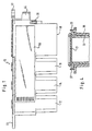
- the modular reagent cartridge 10 shown in FIG. 1 is formed in that several reagent containers 12, 14, 16 and 18 by means of integrally molded Coupling devices directly connected to each other are.
- the reagent containers 12, 14 and 16 trained equally and consist of one essentially cuboid-shaped container made with a rubber disk 21 Silicone is sealed, which is slotted and a Filling the reagent containers in a special Manufacturing step and automatic removal of Aliquots in reagent positions in the analyzer enabled.
- the type and shape of the slot which is in cross, star or Straight line shape is preferably so designed that this after extending the filling mandrel a filling machine or pipetting needle of the analyzer tightly closed again.
- the Coupling device As shown in Fig. 2, there is in one piece to the Coupling device molded onto the reagent container positive rail guides 22 with rectangular Cross section that are pushed into each other, the individual reagent container the shown Form the reagent cartridge.
- the Rail guide 22 At the top of the Rail guide 22 is the top of the reagent containers 12 to 18 in the area of the rail guides 22 introduced so that a stop 24 forms, the one Aligning the reagent containers in alignment ensures.
- the rail guides 22 are of this type trained that on each side of a Reagent container a U-shaped seen in cross section Rail pair is arranged, the openings of the "U" point to each other.
- the reagent container 18 shown in the figures is off a holding frame 26 is formed, the total of four containers 28, 30, 32 and 34 which has a smaller volume than have the reagent containers 12, 14 and 16.
- the Containers 28 to 34 have one essentially cylindrical shape and are also on the top with a protected rubber plate 21 closed. Here are the containers 28 to 34 in corresponding chambers in the Holding frame 26 used.
- All of the containers 28 to 34 are in the holding frame 26 rotatably received, the container 34 on its Underside has a molded ring gear 36.
- the holding frame 26 is in its rear area, i.e. in the Area of the ring gear 36 is open, so that the 1 to 3 right side from an access to the Sprocket 36 is enabled.
- This can be used for mixing of a suspension contained in the container 34 a drive done via a rack or a gear.
- the container 34 is driven to rotate about its Longitudinal axis offset by 180 °.
- suspensions are obtained as a homogeneous suspension on the inner wall of the container 34 extending in the longitudinal direction Inner ribs 38 (see FIG. 3) formed, the axially parallel are aligned. As a result, the mix is during Rotation movement around the vertical axis from a jacket Ring zone of the container with vortex formation in the direction of the central extraction zone displaced.
- the container 34 is in the holding frame 36 fixed by two locking lugs 37, 39, which over an edge of the Grab container. Due to the flexible training of the The container 34 can snap into the one shown in FIG. 4 Position are pressed or removed from this. Instead of the container 34, however, a container can also be used 28 to 32 in the rightmost in Fig. 2 Chamber are used.
- a Connection device in the form of two flexible locking brackets 40, 41 formed, which is a non-positive connection between the reagent cartridge 10 and an analyzer manufactures.
- a mounting wall 42 is one Analyzer indicated schematically, the corresponding Has openings in which the locking bracket 40 and 41st can snap into place. Due to the flexible training of the essential U-shaped locking bracket and by the most free Provided at the end of the locking bracket locking lugs Reagent cartridge as often and easily in the insert corresponding openings of the mounting wall 42 and is thereby non-positively connected to the analyzer.
- a Flag 44 provided below the latching bracket, which also is integrally formed, serves to activate a Sensor device, for example a light barrier, around which Analyzer to notify that the reagent cartridge is properly inserted in the analyzer.
- a handle 46 On the left in Figs. 1 to 3 of the Reagent cartridge, i.e. is on the front a handle 46, which is also integrally formed Rail guide with which this to the Reagent container 12 is coupled.
- the handle is L-shaped trained and has one on its shorter leg Finger opening 48, which is engaged with a finger can be.
- a handle can be used, its horizontal running leg a molded extension part has the length of the missing reagent container equivalent. This can change the length of the reagent cartridge be kept constant.
- all of the reagent containers are 12 to 18 on their sides over about half the height of the container trained that on the outside of the reagent cartridge a flat, coherent surface is formed, which extends across the reagent containers 12 to 18.
- the rounded corners seen in cross section have, in their upper region, i.e. in the field of Rail guides 22 formed so that after Coupling the reagent containers together forms contiguous surface. Then on this surface a label 50 can be stuck on smoothly, the required Contains data.
- All reagent containers are like this on their top edge procure that an edge with sufficient area for the Application of a liquid-tight seal, e.g. one Heat seal film is available. Still is ensures that the heat seal film again without problems can be removed, which is achieved in that a Tamper-evident closure by means of an adhesive connection with the Heat sealing film is connected, which is then when removing the Tamper-evident closure is also removed. in this connection the tamper-evident closure is carried out in one operation via the entire reagent cartridge applied and covered also the locking bracket 40, 41 of the coupling device. hereby ensures that it is used in the analyzer the tamper-evident closure by the user by simple Removal from the reagent cartridge must be removed.
- the Invention not on the container sizes shown and types is limited, which in different numbers in of the reagent cartridge can be used. All The reagent container and the handle are preferably made of immunological inert plastic, such as Polypropylene. The volumes of the vessels can however, vary as needed.
Landscapes
- Chemical & Material Sciences (AREA)
- Health & Medical Sciences (AREA)
- Immunology (AREA)
- Pathology (AREA)
- Analytical Chemistry (AREA)
- Biochemistry (AREA)
- General Health & Medical Sciences (AREA)
- General Physics & Mathematics (AREA)
- Physics & Mathematics (AREA)
- Life Sciences & Earth Sciences (AREA)
- Clinical Laboratory Science (AREA)
- Chemical Kinetics & Catalysis (AREA)
- Engineering & Computer Science (AREA)
- Mechanical Engineering (AREA)
- Automatic Analysis And Handling Materials Therefor (AREA)
- Containers Having Bodies Formed In One Piece (AREA)
- Devices For Use In Laboratory Experiments (AREA)
- Extraction Or Liquid Replacement (AREA)
Abstract
Description
Die vorliegende Erfindung betrifft eine Reagenzienkartusche zur Bevorratung von gebrauchsfertigen, biochemischen Reagenzien in flüssiger Form, die eine einfache Beladung und Verwendung in einem vollautomatischen Analysengerät ermöglichen soll.The present invention relates to a reagent cartridge for storing ready-to-use, biochemical Reagents in liquid form that are easy to load and Use in a fully automatic analyzer should enable.
Reagenzienbehälter sind aus dem Stand der Technik grundsätzlich bekannt. So beschreibt beispielsweise die EP 0 564 970 A3 ein sogenanntes Reagenzien-Kit, bei dem drei Reagenzienbehälter in einem quaderförmigen Rahmen gehalten sind. Hierbei besitzt das Gehäuse im Boden und im Deckel Öffnungen, die eine Luftzirkulation durch den Innenraum des Gehäuses ermöglichen, um eine gleichmäßige Kühlung der Reagenzbehälter zu gewährleisten.Reagent containers are from the prior art basically known. For example, the EP 0 564 970 A3 a so-called reagent kit, in which three Reagent container held in a cuboid frame are. Here, the housing has in the bottom and in the lid Openings that allow air to circulate through the interior of the Allow housing to cool evenly Ensure reagent containers.
Die EP 0 435 481 A2 beschreibt eine Analysenvorrichtung mit einer Drehscheibe, auf der Reagenzienbehälter angeordnet sind. Hierbei sind jeweils zwei der kuchenstückförmigen Behälter über einen aufschnappbaren Deckel zu einer Doppelpackung miteinander verbunden. Zur erleichterten Herstellung kann die Doppelpackung auch einstückig ausgebildet sein. EP 0 435 481 A2 also describes an analysis device a turntable, arranged on the reagent container are. Here are two of the cake pieces Container over a snap-on lid to one Double pack connected together. To make it easier The double pack can also be produced in one piece be trained.
Die EP 0313 977 A2 beschreibt eine Stelleinheit für Reagenz-, Probenröhrchen oder dergleichen, die durch einen Block oder Zylinder mit einer nach oben offenen Ausnehmung gebildet wird. Die Seitenflächen des Blocks oder Zylinders sind mit sich senkrecht zu dieser Fläche erstreckenden Klemmöffnungen und sich ebenfalls senkrecht zu dieser Seitenfläche erstreckenden Klemmvorsprüngen versehen. Die Ausbildung von Klemmöffnung und Klemmvorsprüngen mit senkrecht zu den Seitenflächen des Blocks oder Zylinders sich erstreckenden Flächen soll gewährleisten, daß mehrere Stelleinheiten in beliebiger Zahl und in allen Richtungen der waagrechten Ebene zu einem Verbund zusammengefügt werden können.EP 0313 977 A2 describes an actuating unit for reagent, sample tubes or the like, which is formed by a block or cylinder with a recess open at the top becomes. The side surfaces of the block or cylinder are perpendicular to this surface extending clamping openings and also extending perpendicular to this side surface Provide clamping projections. The formation of the clamping opening and clamping projections with perpendicular to the side surfaces of the block or cylinder Areas should ensure that several actuators in any number and in all directions the horizontal level can be joined to form a composite.
Die US 5,322,668 beschreibt eine kuchenstückförmige Halterung für Reagenzbehälter, bei der die Reagenzbehälter in vorgeschriebenen Positionen gehalten werden, zur Verwendung in einem Analysengerät. Die Halterung für die Reagenzbehälter weist weiterhin eine Vielzahl von Reaktionsküvetten auf, die mit Antikörper-Reagenzien bestückt sein können.US 5,322,668 describes a cake-shaped holder for reagent containers, at which the reagent containers are held in prescribed positions for use in an analyzer. The holder for the reagent container still has a variety of reaction cuvettes, which can be equipped with antibody reagents.
Aus der FR 2110030 A ist eine Vorrichtung bekannt, bei der eine Vielzahl von Behältern, wie Becher oder Hohlräume als integrale Bestandteile durch eine horizontales Trägerteil und vertikale Trägerteile miteinander verbunden sind. Über schwalbenschwanzförmige Kopplungseinrichtungen kann eine Reihe solcher Vorrichtungen miteinander verbunden werden.From FR 2110030 A a device is known in which a variety of containers, such as Cups or cavities as integral parts through a horizontal support part and vertical support parts are interconnected. Via dovetail-shaped coupling devices a number of such devices can be interconnected.
In der FR 2537096 A1 wird ein Tablettenröhrchen beschreiben, das einen zylindrischen Körper aufweist, der an einem Ende einen dünnen, mehreckigen über den zylindrischen Körper hervorstehenden Verschluss aufweist. Dieser Verschluss kann Kopplungseinrichtungen aufweisen, durch die mehrere dieser Tablettenröhrchen miteinander verbunden werden können.FR 2537096 A1 describes a tablet tube that has a cylindrical body has at one end a thin, polygonal over the cylindrical body protruding closure. This closure can have coupling devices through which several of these tablet tubes can be connected.
Aus der DE 3903 645 A1 ist eine Vorrichtung für die Aufbewahrung von Reagenzien, die Durchführung von Tests und die Aufbewahrung von Testergebnissen, bestehend aus einem Gefäß mit einer Öffnung in der Oberseite und einem aufsteckbarenVerschluß, bekannt. Die Seitenwände des Gefäßes weisen im oberen Bereich einen Versprung nach innen auf. Dadurch können mehrere Gefäße übereinander gesteckt werden.DE 3903 645 A1 describes a device for storing reagents which Conducting tests and storing test results, consisting of a Vessel with an opening in the top and a snap-on closure, known. The Side walls of the vessel have an inward protrusion in the upper region. Thereby several vessels can be placed one above the other.
Die EP 0125996 A1 betrifft einen modularen Träger in Form eines quaderförmigen Korbes zur Aufnahme von Behältern variabler Größe zur Verwendung in Analysengeräten. Über seitliche Kopplungseinrichtungen kann eine Reihe solcher Träger miteinander verbunden werden. EP 0125996 A1 relates to a modular carrier in the form of a cuboid basket for holding containers of variable size for use in analysis devices. about lateral coupling devices can connect a number of such carriers together become.
Schließlich beschreibt die EP 0 502 638 A2 eine automatische Analysenvorrichtung mit einer Vielzahl von länglichen Reagenzienbehältern, die von einem automatischen Handhabungssystem transportiert werden. Um einen Transport dieser Reagenzienbehälter zu ermöglichen, sind diese mit seitlichen Flanschen sowie Vorsprüngen versehen.Finally, EP 0 502 638 A2 describes an automatic one Analyzer with a variety of elongated Reagent containers by an automatic Handling system can be transported. For transportation To enable this reagent container, these are included side flanges and protrusions.
Es ist das der Erfindung zugrundeliegende Problem (Aufgabe), ein Mittel zur Handhabung von Reagenzien zu schaffen, das eine flexible Handhabung auch bei unterschiedlichsten Reagenzienchargen ermöglicht.It is the problem (object) on which the invention is based, to provide a means of handling reagents that flexible handling even with the most varied Reagent batches enabled.
Die Lösung dieser Aufgabe erfolgt durch die Merkmale des Anspruchs 1. Erfindungsgemäß ist eine modulare Reagenzienkartusche vorgesehen, die dadurch gebildet ist, daß mehrere Reagenzienbehälter mittels einstückig angeformter Kopplungseinrichtungen unmittelbar miteinander verbunden sind.This problem is solved by the features of Claim 1. According to the invention is a modular Reagent cartridge is provided, which is formed in that several reagent containers by means of integrally molded Coupling devices directly connected to each other are.
Die Erfindung schafft erstmals ein modulares System aus Reagenzienbehältern, wobei die einzelnen Behälter durch die einstückig angeformten Kopplungseinrichtungen zu einer Reagenzienkartusche verbunden werden können. Eine derartige Kartusche kann dann mit nur einem Handgriff in ein Analysengerät eingesetzt werden. Durch den modularen Aufbau der Reagenzienkartusche können ferner die Reagenzienbehälter während des Abfüllprozesses einzeln bearbeitet werden und nach erfolgter Produktion werden diese Reagenzienbehälter in einem einzigen Konfektionierungsschritt zu einer Reagenzienkartusche montiert. Hierbei sind keine weiteren Kopplungselemente oder dergleichen erforderlich. Vielmehr werden die einzelnen Reagenzienbehälter unmittelbar ohne Zwischenschaltung von zusätzlichen Verbindungselementen miteinander verbunden. Hierdurch ist die freie Kombinierbarkeit unterschiedlichster Reagenzienchargen immer gewährleistet. Somit ergeben sich durch die erfindungsgemäße Reagenzienkartusche noch nicht dagewesene Handhabungsvorteile, die insbesondere im Zuge des Produktionsprozesses auch Zeit einsparen, da das Befüllen der Reagenzienbehälter im noch nicht montierten Zustand erfolgen kann und nach Konfektionierung der Kartusche diese als eine Einheit zu handhaben ist. Gleichzeitig lassen sich eventuell schadhaft gewordene Behälter ohne weiteres durch neue Behälter ersetzen, ohne daß die gesamte Kartusche ausgewechselt werden müßte. Darüber hinaus ist es möglich, Reagenzienbehälter mit unterschiedlichen Größen bzw. Volumina miteinander zu einer Kartusche zu kombinieren, wobei die Kombination beliebig vorgenommen werden kann. Dies bedeutet gleichzeitig, daß nicht eine große Anzahl unterschiedlicher Reagenzienkartuschen bereitgestellt werden muß. Vielmehr kann jede Kartusche mit der gewünschten Behälterkombination individuell zusammengestellt werden.The invention creates a modular system for the first time Reagent containers, the individual containers through the integrally molded coupling devices to a Reagent cartridge can be connected. Such Cartridge can then be moved into one with just one hand Analyzer are used. Thanks to the modular structure the reagent cartridge can also the reagent container processed individually during the filling process and After production, these reagent containers are in a single assembly step to one Reagent cartridge installed. There are no others here Coupling elements or the like required. Much more the individual reagent containers are immediately without Interposition of additional connecting elements connected with each other. This is the free Combinability of different reagent batches always guaranteed. Thus, the result of the invention Reagent cartridge not yet seen Handling advantages, especially in the course of Production process also save time because the filling of the Reagent containers are made in the not yet assembled state can and after assembling the cartridge as one Unity is to be handled. At the same time, you can Containers that have become defective are easily replaced by new ones Replace the container without the entire cartridge should be replaced. In addition, it is possible Reagent containers with different sizes or volumes to combine with each other to form a cartridge, the Combination can be made arbitrarily. this means at the same time that not a large number of different Reagent cartridges must be provided. Rather can each cartridge with the desired container combination can be put together individually.
Vorteilhafte Ausführungsformen der Erfindung sind durch die Unteransprüche gekennzeichnet.Advantageous embodiments of the invention are characterized by Subclaims marked.
Nach einer ersten vorteilhaften Ausführungsform kann zumindest ein Reagenzienbehälter eine vorzugsweise einrastende Verbindungseinrichtung aufweisen, um eine kraftschlüssige Verbindung zwischen der Reagenzienkartusche und einem Analysengerät herzustellen. Ein derartiger Reagenzienbehälter, der gewissermaßen ein Grundelement des modularen Systems darstellen kann, ermöglicht eine kraftschlüssige Verbindung zwischen der Reagenzienkartusche und dem Analysengerät, die aufgrund des speziellen Rastmechanismus beliebig oft hergestellt und leicht wieder gelöst werden kann. Vorteilhafterweise ist die Rastverbindung ebenfalls einstückig an den Reagenzienbehälter angeformt.According to a first advantageous embodiment at least one reagent container preferably one have latching connection device to a non-positive connection between the reagent cartridge and manufacture an analyzer. Such one Reagent container, which is a basic element of the modular system, enables a non-positive connection between the reagent cartridge and the analyzer, which due to the special Locking mechanism made as often as required and easily restored can be solved. The locking connection is advantageous also integrally molded onto the reagent container.
Nach einer weiteren Ausbildung der Erfindung besteht ein Reagenzienbehälter aus einem Halterahmen und mindestens einem Behältnis, das ein geringeres Volumen als ein Reagenzienbehälter besitzt. Diese Ausführungsform ermöglicht auch die Verwendung von kleinvolumigen Reagenzienbehältnissen, wobei diese in dem Halterahmen aufgenommen sind, der wiederum ein Modul des Systems bildet. Hierdurch ergibt sich gleichzeitig der Vorteil, daß auch mehrere der Behältnisse mit geringerem Volumen in einem einzigen Halterahmen aufgenommen werden können, wobei sich ein und derselbe Halterahmen auch für mehrere Behältnisse mit unterschiedlichen Volumina eignet.According to a further embodiment of the invention, there is a Reagent container consisting of a holding frame and at least one Container that has a smaller volume than one Owns the reagent container. This embodiment enables also the use of small volume Reagent containers, these in the holding frame are included, which in turn forms a module of the system. This also has the advantage that several of the smaller volume containers in one single holding frame can be accommodated one and the same holding frame for several containers different volumes.
Besonders vorteilhaft ist es, wenn zumindest ein Behältnis drehbar in dem Halterahmen aufgenommen ist und dabei vorzugsweise einen angeformten Zahnkranz aufweist. Durch die drehbare Aufnahme kann das Behältnis, vorzugsweise mittels des angeformten Zahnkranzes, eine Rotationsbewegung um seine vertikale Achse durchführen, um eine in dem Behältnis enthaltene Suspension zu durchmischen. Besonders vorteilhaft ist es hierbei, wenn der Halterahmen teilweise offen ausgebildet ist, derart, daß ein Zugang zu einer Seite oder Unterseite des Behältnisses ermöglicht ist. Hierdurch läßt sich ein Antrieb an das Behältnis ankoppeln, damit dieses in eine Drehung versetzt wird. Ein solcher Antrieb kann beispielsweise durch ein Zahnrad oder eine Zahnstange erfolgen. Es können auch mehrere der Behältnisse mit Zahnkränzen oder dergleichen versehen sein, so daß der Antrieb lediglich an einem der Behältnisse angreifen muß. Durch Übertragung der Drehbewegung können dann mehrere der in dem Halterahmen aufgenommenen Behältnisse in Drehung versetzt werden.It is particularly advantageous if at least one container is rotatably received in the holding frame and thereby preferably has a molded ring gear. Through the rotatable receptacle can, preferably by means of of the molded ring gear, a rotational movement around its Perform vertical axis to one in the container Mix the contained suspension. Particularly advantageous it is here when the holding frame is partially open is designed such that access to one side or Bottom of the container is enabled. This leaves connect a drive to the container so that it is in a rotation is set. Such a drive can for example by a gear or a rack respectively. You can also use several of the containers Sprockets or the like may be provided so that the Drive only has to attack one of the containers. By transmitting the rotary movement, several of the in the holding frame received rotated become.
Nach einer weiteren Ausbildung der Erfindung ist das in dem Halterahmen aufgenommene Behältnis fixiert. Hierdurch wird sichergestellt, daß das Behältnis nicht versehentlich aus dem Halterahmen herausfällt und daß bei Auferlegung einer Drehbewegung das Behältnis stets an der gleichen Stelle im Rahmen verbleibt. Die Fixierung kann dabei vorteilhafterweise durch elastisch wegfedernde Rastnasen erfolgen, was eine sehr schnelle und einfache Handhabung gewährleistet. According to a further embodiment of the invention that is in the Holding frame fixed container. This will ensures that the container is not accidentally removed from the Retaining frame falls out and that when imposing one Rotational movement of the container always in the same place in the Frame remains. The fixation can advantageously done by elastically resilient locking lugs, which is a very quick and easy handling guaranteed.
Weiter ist es vorteilhaft, wenn die erfindungsgemäße Reagenzienkartusche einen Griff mit einer einstückig angeformten Kopplungseinrichtung aufweist. Ein derartiger Griff läßt sich in gleicher Weise wie die Reagenzienbehälter an der Reagenzienkartusche ankoppeln, so daß eine gute Handhabung der Reagenzienkartusche sichergestellt ist, insbesondere wenn eine Vielzahl von Reagenzienkartuschen nebeneinander angeordnet wird. In diesem Fall ist es besonders vorteilhaft, wenn der Griff eine Fingeröffnung aufweist, da dann ein Herausziehen der Kartusche aus dem Analysengerät mit nur einem Finger möglich ist. Um die Flexibilität der modularen Reagenzienkartusche zu erhöhen, kann der Griff auch ein vorzugsweise einstückig eingeformtes Verlängerungsteil aufweisen, das der Länge zumindest eines Reagenzienbehälters entspricht. Hierdurch wird eine jeweils konstante Länge der Reagenzienkartusche gewährleistet, auch wenn ein Behälter weniger angekoppelt wird, da der Griff die Länge des fehlenden Behälters kompensiert.It is also advantageous if the invention Reagent cartridge has a handle with one piece molded coupling device. Such one Handle can be used in the same way as the reagent container couple to the reagent cartridge so that a good one Handling of the reagent cartridge is ensured, especially if a variety of reagent cartridges is arranged side by side. In this case it is particularly advantageous if the handle has a finger opening has, since then pulling the cartridge out of the Analyzer with only one finger is possible. To the Increasing the flexibility of the modular reagent cartridge, the handle can also be molded in one piece Have extension part, the length of at least one Corresponds to the reagent container. This will make one ensures constant length of the reagent cartridge, too if a container is coupled less because the handle Length of the missing container compensated.
Die erfindungsgemäß vorgesehene Kopplungseinrichtung kann in vorteilhafter Weise durch formschlüssige Schienenführungen gebildet sein, die im gekoppelten Zustand selbsttätig verklemmen. Hierdurch müssen die einzelnen Reagenzienbehälter lediglich an den Schienenführungen "ineinander geschoben" werden, was eine sehr schnelle Handhabung ermöglicht. Der Querschnitt der Schienenführungen kann jede geeignete Form aufweisen, beispielsweise rechteckig oder schwalbenschwanzförmig sein. Besonders vorteilhaft ist es jedoch, wenn die Schienenführung einen Anschlag aufweist. Hierdurch muß bei Konfektionierung der Reagenzienkartusche nicht darauf geachtet werden, daß sämtliche Reagenzienbehälter an der Oberseite bündig abschließen, da dies durch den vorgesehenen Anschlag sichergestellt wird.The coupling device provided according to the invention can be in advantageously by positive rail guides be formed automatically in the coupled state jam. This means that the individual reagent containers simply "pushed into each other" on the rail guides be, which enables very quick handling. The Cross section of the rail guides can be any suitable shape have, for example rectangular or be dovetailed. It is particularly advantageous however, if the rail guide has a stop. This must be done when assembling the reagent cartridge care is not taken to ensure that all Close the top of the reagent container so that it is flush this is ensured by the intended stop.
Nach einer weiteren vorteilhaften Ausbildung der Erfindung weisen die Reagenzienbehälter die gleiche Länge und/oder Breite auf, d.h. die Behälterabmessungen in einer Dimension sind gleich groß. Hierdurch ergibt sich eine Kartusche mit einheitlicher Formgebung, d.h. mit konstanter Breite.According to a further advantageous embodiment of the invention the reagent containers have the same length and / or Width, i.e. the container dimensions in one dimension are the same size. This results in a cartridge with uniform design, i.e. with constant width.
Zum Schutz der Behälter kann die Reagenzienkartusche einen aufsetzbaren Deckel aufweisen, der auf die Oberseite der Kartusche aufgestülpt wird.The reagent cartridge can be used to protect the container have attachable lid that on the top of the Cartridge is put up.
Schließlich ist es besonders vorteilhaft, wenn die Reagenzienkartusche zumindest teilweise an ihrer Außenseite eine weitgehend ebene, zusammenhängende Fläche bildet, die sich über die Reagenzienbehälter erstreckt. Hierdurch kann ein Etikett, das alle relevanten, testspezifischen Daten in codierter Form enthält, glatt auf die Außenseite der Reagenzienkartusche aufgebracht werden, obwohl diese aus mehreren Reagenzienbehältern zusammengesetzt ist.Finally, it is particularly advantageous if the Reagent cartridge at least partially on the outside forms a largely flat, coherent surface that extends across the reagent containers. This can a label that contains all relevant, test-specific data in contains coded form, smooth on the outside of the Reagent cartridge can be applied even though this is from is composed of several reagent containers.
Nachfolgend wird eine vorteilhafte Ausführungsform der Erfindung rein beispielhaft unter Bezugnahme auf die beigefügten Zeichnungen beschrieben. Es zeigen:
- Fig. 1
- eine Seitenansicht einer modularen Reagenzienkartusche;
- Fig. 2
- einen Querschnitt durch die Reagenzienkartusche von Fig. 1;
- Fig. 3
- eine Draufsicht auf die Reagenzienkartusche von Fig. 1; und
- Fig. 4
- einen Querschnitt entlang der Linie IV-IV in Fig. 3.
- Fig. 1
- a side view of a modular reagent cartridge;
- Fig. 2
- a cross section through the reagent cartridge of Fig. 1;
- Fig. 3
- a plan view of the reagent cartridge of Fig. 1; and
- Fig. 4
- a cross section along the line IV-IV in Fig. 3rd
Die in Fig. 1 dargestellte modulare Reagenzienkartusche 10
ist dadurch gebildet, daß mehrere Reagenzienbehälter 12, 14,
16 und 18 mittels einstückig angeformter
Kopplungseinrichtungen unmittelbar miteinander verbunden
sind. Hierbei sind die Reagenzienbehälter 12, 14 und 16
gleich ausgebildet und bestehen aus einem im wesentlichen
quaderförmigen Behälter, der mit einer Gummironde 21 aus
Silikon verschlossen ist, die geschlitzt ist und eine
Befüllung der Reagenzienbehälter in einem speziellen
Herstellungsschritt und eine automatische Entnahme von
Aliquots in Reagenzienpositionen im Analysengerät ermöglicht.
Die Art und Form des Schlitzes, der in Kreuz-, Stern- oder
Geradenform ausgebildet sein kann, ist vorzugsweise so
gestaltet, daß sich dieser nach Ausfahren des Abfülldorns
einer Abfüllmaschine oder Pipettiernadel des Analysengerätes
wieder dicht verschließt.The
Wie Fig. 2 zeigt, besteht die einstückig an die
Reagenzienbehälter angeformte Kopplungseinrichtung aus
formschlüssigen Schienenführungen 22 mit rechteckigem
Querschnitt, die ineinander geschoben werden, wobei die
einzelnen Reagenzienbehälter die dargestellte
Reagenzienkartusche bilden. Am oberen Ende der
Schienenführung 22 ist der obere Rand der Reagenzienbehälter
12 bis 18 in dem Bereich der Schienenführungen 22
hineingeführt, so daß sich ein Anschlag 24 bildet, der ein
fluchtendes Ineinandersetzen der Reagenzienbehälter
sicherstellt. Die Schienenführungen 22 sind derart
ausgebildet, daß an jeweils einer Seite eines
Reagenzienbehälters ein im Querschnitt gesehen U-förmiges
Schienenpaar angeordnet ist, wobei die Öffnungen des "U"
aufeinanderzu weisen. Durch diese parallel beabstandeten
Schienen wird gewissermaßen ein rechteckiger Querschnitt
gebildet, in den die Schienen des zu koppelnden
Reagenzienbehälters eingeführt werden können. Diese Schienen
befinden sich auf der jeweils anderen Seite eines
Reagenzienbehälters und sind im Querschnitt L-förmig
ausgebildet, wobei beim Aneinanderkoppeln zweier Behälter ein
Schenkel des "L" jeweils einer der im Querschnitt U-förmigen
Schienen gleitet. Um ein selbsttätiges Verklemmen der
Reagenzienbehälter bei Erreichen des Anschlags 24 zu
erzielen, ist ein Schenkel der im Querschnitt U-förmigen
Schienen leicht keilförmig ausgebildet, so daß sich beim
Einschieben des zu koppelnden Reagenzienbehälters eine
leichte Klemmwirkung ergibt, die bei Erreichen des Anschlags
24 maximal ist. Schließlich weisen die im Querschnitt L-förmigen
Schienen an ihren Enden jeweils eine Verlängerung
auf, die mit Einlaufschrägen versehen ist, um das "Einfädeln"
zu erleichtern.As shown in Fig. 2, there is in one piece to the
Coupling device molded onto the reagent container
positive rail guides 22 with rectangular
Cross section that are pushed into each other, the
individual reagent container the shown
Form the reagent cartridge. At the top of the
Der in den Figuren dargestellte Reagenzienbehälter 18 ist aus
einem Halterahmen 26 gebildet, der insgesamt vier Behältnisse
28, 30, 32 und 34 aufnimmt, die ein geringeres Volumen als
die Reagenzienbehälter 12, 14 und 16 besitzen. Die
Behältnisse 28 bis 34 besitzen eine im wesentlichen
zylindrische Form und sind an der Oberseite ebenfalls mit
einer geschützten Gummironde 21 verschlossen. Hierbei sind
die Behältnisse 28 bis 34 in entsprechende Kammern in dem
Halterahmen 26 eingesetzt.The
Sämtliche Behältnisse 28 bis 34 sind in dem Halterahmen 26
drehbar aufgenommen, wobei das Behältnis 34 an seiner
Unterseite einen angeformten Zahnkranz 36 aufweist. Der
Halterahmen 26 ist dabei in seinem hinteren Bereich, d.h. im
Bereich des Zahnkranzes 36 offen ausgebildet, so daß von der
in den Fig. 1 bis 3 rechten Seite aus ein Zugang zu dem
Zahnkranz 36 ermöglicht ist. Hierdurch kann zur Durchmischung
einer in dem Behältnis 34 enthaltenen Suspension ein Antrieb
über eine Zahnstange oder ein Zahnrad erfolgen. Durch diesen
Antrieb wird das Behältnis 34 in eine Drehung um seine
Längsachse um jeweils 180° versetzt. Um dabei Suspensionen
als homogene Suspension zu erhalten, sind an der Innenwandung
des Behältnisses 34 sich in Längsrichtung erstreckende
Innenrippen 38 (vgl. Fig. 3) angeformt, die achsparallel
ausgerichtet sind. Hierdurch wird das Mischgut während der
Drehbewegung um die vertikale Achse aus einer mantelnahen
Ringzone des Behältnisses unter Wirbelbildung in Richtung der
achszentralen Entnahmezone verdrängt. All of the
Wie Fig. 4 zeigt, ist das Behältnis 34 in dem Halterahmen 36
durch zwei Rastnasen 37, 39 fixiert, die über einen Rand des
Behältnisses greifen. Aufgrund der flexiblen Ausbildung der
Rastnasen kann das Behältnis 34 in die in Fig. 4 dargestellte
Stellung gedrückt werden oder aus dieser entfernt werden.
Anstelle des Behältnisses 34 kann jedoch auch ein Behältnis
28 bis 32 in die in Fig. 2 am weitesten rechts dargestellte
Kammer eingesetzt werden.4, the
An der in den Fig. 1 bis 3 rechten Seite des Halterahmens 26,
d.h. am hinteren Ende der Reagenzienkartusche, ist eine
Verbindungseinrichtung in Form von zwei flexiblen Rastbügeln
40, 41 angeformt, die eine kraftschlüssige Verbindung
zwischen der Reagenzienkartusche 10 und einem Analysengerät
herstellt. In Fig. 2 ist eine Montagewand 42 eines
Analysengerätes schematisch angedeutet, die entsprechende
Öffnungen aufweist, in welche die Rastbügel 40 und 41
einrasten können. Durch die flexible Ausbildung der im
wesentlichen U-förmigen Rastbügel und durch die am freien
Ende der Rastbügel vorgesehenen Rastnasen läßt sich die
Reagenzienkartusche beliebig oft und leicht in die
entsprechenden Öffnungen der Montagewand 42 einsetzen und ist
dadurch kraftschlüssig mit dem Analysengerät verbunden. Eine
unterhalb der Rastbügel vorgesehene Fahne 44, die ebenfalls
einstückig angeformt ist, dient zur Aktivierung einer
Sensoreinrichtung, beispielsweise einer Lichtschranke, um dem
Analysengerät mitzuteilen, daß die Reagenzienkartusche
ordnungsgemäß in das Analysengerät eingesetzt ist.On the right side of the holding
An der in den Fig. 1 bis 3 linken Seite der
Reagenzienkartusche, d.h. an deren Vorderseite befindet sich
ein Griff 46, der ebenfalls eine einstückig angeformte
Schienenführung aufweist, mit der dieser an den
Reagenzienbehälter 12 gekoppelt ist. Der Griff ist L-förmig
ausgebildet und weist an seinem kürzeren Schenkel eine
Fingeröffnung 48 auf, in die mit einem Finger eingegriffen
werden kann. On the left in Figs. 1 to 3 of the
Reagent cartridge, i.e. is on the front
a
Sofern eine Reagenzienkartusche zusammengestellt wird, bei
der beispielsweise nur zwei der Behälter 12 bis 16 vorgesehen
sind, kann ein Griff verwendet werden, dessen horizontal
verlaufender Schenkel ein eingeformtes Verlängerungsteil
aufweist, das der Länge des fehlenden Reagenzienbehälters
entspricht. Hierdurch kann die Länge der Reagenzienkartusche
konstant gehalten werden.If a reagent cartridge is put together, at
for example, only two of the
Wie Fig. 1 zeigt, sind sämtliche Reagenzienbehälter 12 bis 18
an ihren Seiten über etwa die halbe Behälterhöhe derart
ausgebildet, daß an der Außenseite der Reagenzienkartusche
eine ebene, zusammenhängende Fläche gebildet ist, die sich
über die Reagenzienbehälter 12 bis 18 erstreckt. Hierzu sind
die Behälter, die im Querschnitt gesehen abgerundete Ecken
aufweisen, in ihrem oberen Bereich, d.h. im Bereich der
Schienenführungen 22 so ausgebildet, daß sich nach
Aneinanderkopplung der Reagenzienbehälter die
zusammenhängende Fläche bildet. Auf diese Fläche kann dann
ein Etikett 50 glatt aufgeklebt werden, das erforderliche
Daten enthält.As shown in FIG. 1, all of the reagent containers are 12 to 18
on their sides over about half the height of the container
trained that on the outside of the reagent cartridge
a flat, coherent surface is formed, which
extends across the
Sämtliche Reagenzienbehälter sind an ihrer Oberkante so
beschaffen, daß ein Rand mit ausreichender Fläche für das
Aufbringen eines flüssigkeitsdichten Verschlusses, z.B. einer
Heißsiegelfolie, zur Verfügung steht. Weiterhin ist
gewährleistet, daß die Heißsiegelfolie problemlos wieder
entfernt werden kann, was dadurch erreicht wird, daß ein
Originalitätsverschluß durch eine Klebeverbindung mit der
Heißsiegelfolie verbunden wird, die dann beim Entfernen des
Originalitätsverschlusses ebenfalls entfernt wird. Hierbei
wird der Originalitätsverschluß in einem Arbeitsgang über die
gesamte Reagenzienkartusche aufgebracht und überdeckt dabei
auch die Rastbügel 40, 41 der Kopplungseinrichtung. Hierdurch
ist sichergestellt, daß vor einem Einsatz im Analysengerät
der Originalitätsverschluß vom Anwender durch einfaches
Abziehen von der Reagenzienkartusche entfernt werden muß. All reagent containers are like this on their top edge
procure that an edge with sufficient area for the
Application of a liquid-tight seal, e.g. one
Heat seal film is available. Still is
ensures that the heat seal film again without problems
can be removed, which is achieved in that a
Tamper-evident closure by means of an adhesive connection with the
Heat sealing film is connected, which is then when removing the
Tamper-evident closure is also removed. in this connection
the tamper-evident closure is carried out in one operation via the
entire reagent cartridge applied and covered
also the locking
Aufgrund der obigen Beschreibung sollte klar sein, daß die Erfindung nicht auf die dargestellten Behältergrößen und typen beschränkt ist, die in unterschiedlichster Anzahl in der Reagenzienkartusche Verwendung finden können. Sämtliche Reagenzienbehälter und auch der Griff sind vorzugsweise aus immunologischem inertem Kunststoff, wie beispielsweise Polypropylen, hergestellt. Die Volumina der Gefäße können jedoch je nach Bedarf variieren.From the above description it should be clear that the Invention not on the container sizes shown and types is limited, which in different numbers in of the reagent cartridge can be used. All The reagent container and the handle are preferably made of immunological inert plastic, such as Polypropylene. The volumes of the vessels can however, vary as needed.
Claims (10)
- Modular reagent cartridge (10) for use in automatic analysers, which is formed in that a plurality of reagent containers (12, 14, 16, 18), at least one of which is designed for the direct holding of a reagent, are connected directly to one another by means of coupling devices (22) moulded integrally onto them, the coupling devices being formed by interlocking rail guides (22) which are of slightly wedge-shaped design and automatically become wedged together in the coupled state, the rail guides (22) having stops (24), with the result that the reagent containers (12, 14, 16, 18) are placed into one another in an aligned manner and a clamping action is produced when the stops (24) are reached.
- Modular reagent cartridge according to Claim 1, at least one of the reagent containers (18) having a latching connecting device (40, 41) in order to produce a frictional connection between the reagent cartridge (10) and an analyser.
- Modular reagent cartridge according to Claim 1 or 2, one of the reagent containers (18) comprising a retaining frame (26) and a receptacle (28, 30, 32, 34) which has a smaller volume than one of the other reagent containers (12, 14, 16).
- Modular reagent cartridge according to Claim 3, at least one receptacle (34) being held rotatably in the retaining frame (26) and having a toothed ring (36) moulded onto it.
- Modular reagent cartridge according to Claim 4, the retaining frame (26) being of partially open design in such a manner that access is possible to one side or to the lower side of the receptacle (34).
- Modular reagent cartridge according to one of Claims 3, 4 or 5, the receptacle (34) being fixed in the retaining frame (26) by means of latching lugs (37, 39).
- Modular reagent cartridge according to one of Claims 1 to 6, the latter having a handle (46) with a rail guide (22) moulded integrally onto it.
- Modular reagent cartridge according to Claim 7, the handle having an extension part which corresponds to the length of at least one reagent container (12).
- Modular reagent cartridge according to Claim 7 or 8, the handle (46) having a finger opening (48).
- Modular reagent cartridge according to one of Claims 1 to 9, the outer side of the latter forming a largely flat, cohesive surface which extends over the reagent containers (12, 14, 16, 18).
Priority Applications (1)
| Application Number | Priority Date | Filing Date | Title |
|---|---|---|---|
| SI9630549T SI0871894T1 (en) | 1995-11-02 | 1996-10-30 | Modular reagent cartridge |
Applications Claiming Priority (3)
| Application Number | Priority Date | Filing Date | Title |
|---|---|---|---|
| DE19540877A DE19540877C2 (en) | 1995-11-02 | 1995-11-02 | Modular reagent cartridge |
| DE19540877 | 1995-11-02 | ||
| PCT/EP1996/004705 WO1997016734A1 (en) | 1995-11-02 | 1996-10-30 | Modular reagent cartridge |
Publications (2)
| Publication Number | Publication Date |
|---|---|
| EP0871894A1 EP0871894A1 (en) | 1998-10-21 |
| EP0871894B1 true EP0871894B1 (en) | 2002-09-18 |
Family
ID=7776464
Family Applications (1)
| Application Number | Title | Priority Date | Filing Date |
|---|---|---|---|
| EP96937288A Expired - Lifetime EP0871894B1 (en) | 1995-11-02 | 1996-10-30 | Modular reagent cartridge |
Country Status (9)
| Country | Link |
|---|---|
| US (1) | US6149872A (en) |
| EP (1) | EP0871894B1 (en) |
| JP (1) | JPH11515106A (en) |
| AT (1) | ATE224546T1 (en) |
| DE (2) | DE19540877C2 (en) |
| DK (1) | DK0871894T3 (en) |
| ES (1) | ES2183981T3 (en) |
| PT (1) | PT871894E (en) |
| WO (1) | WO1997016734A1 (en) |
Families Citing this family (72)
| Publication number | Priority date | Publication date | Assignee | Title |
|---|---|---|---|---|
| FR2789976B1 (en) | 1999-02-22 | 2001-07-27 | Profil Ind Soc | PACKAGING, TRANSPORTATION PACKAGE AND PACKAGING PACKAGE |
| GB9906477D0 (en) * | 1999-03-19 | 1999-05-12 | Pyrosequencing Ab | Liquid dispensing apparatus |
| US6887429B1 (en) * | 2001-01-26 | 2005-05-03 | Global Fia | Apparatus and method for automated medical diagnostic tests |
| US6692700B2 (en) | 2001-02-14 | 2004-02-17 | Handylab, Inc. | Heat-reduction methods and systems related to microfluidic devices |
| US7010391B2 (en) | 2001-03-28 | 2006-03-07 | Handylab, Inc. | Methods and systems for control of microfluidic devices |
| US6852287B2 (en) | 2001-09-12 | 2005-02-08 | Handylab, Inc. | Microfluidic devices having a reduced number of input and output connections |
| US8895311B1 (en) | 2001-03-28 | 2014-11-25 | Handylab, Inc. | Methods and systems for control of general purpose microfluidic devices |
| US7829025B2 (en) | 2001-03-28 | 2010-11-09 | Venture Lending & Leasing Iv, Inc. | Systems and methods for thermal actuation of microfluidic devices |
| US7458483B2 (en) * | 2001-04-24 | 2008-12-02 | Abbott Laboratories, Inc. | Assay testing diagnostic analyzer |
| US6588625B2 (en) * | 2001-04-24 | 2003-07-08 | Abbott Laboratories | Sample handling system |
| US7666363B2 (en) * | 2001-09-05 | 2010-02-23 | Quest Diagnostics Investments Incorporated | Reagent cartridge |
| US6943030B2 (en) * | 2001-09-07 | 2005-09-13 | Dade Behring Inc. | Multi-compartment reagent container having means to inhibit re-use thereof |
| DE10155400A1 (en) * | 2001-11-10 | 2003-05-28 | Eppendorf Ag | Containers for several different reagents required to run a protocol |
| US7282184B2 (en) * | 2002-04-19 | 2007-10-16 | Cem Corporation | Microwave assisted chemical synthesis instrument with controlled pressure release |
| US7217397B1 (en) * | 2002-08-05 | 2007-05-15 | Astle Thomas W | Precious reagent container and method of use |
| US8490790B2 (en) * | 2003-02-24 | 2013-07-23 | Becton Dickinson France S.A.S. | Plate for holding a group of syringe body objects |
| US20050013743A1 (en) * | 2003-07-18 | 2005-01-20 | Edward Francis Farina | I-shaped slit in a lidstock covering an array of aliquot vessels |
| EP2402089A1 (en) | 2003-07-31 | 2012-01-04 | Handylab, Inc. | Processing particle-containing samples |
| JP4146780B2 (en) * | 2003-10-17 | 2008-09-10 | 株式会社日立ハイテクノロジーズ | Reagent cassette and automatic analyzer using the same |
| JP2005164509A (en) * | 2003-12-05 | 2005-06-23 | Hitachi High-Technologies Corp | Reagent container |
| DE10360526A1 (en) * | 2003-12-22 | 2005-07-14 | Roche Diagnostics Gmbh | Reagent cassette with reagent container for particle-containing reagent for its noninvasive homogenization |
| US8852862B2 (en) | 2004-05-03 | 2014-10-07 | Handylab, Inc. | Method for processing polynucleotide-containing samples |
| DE202005002022U1 (en) * | 2005-02-09 | 2006-06-22 | Emil Lux Gmbh & Co. Kg | Small part container, has one side wall with retaining recess complementary to retaining catch in another side wall, so that two adjacent containers are interconnected by sticking recess and catch together |
| DE102004034801A1 (en) * | 2004-07-19 | 2006-03-16 | Scil Animal Care Company Gmbh | reagent |
| US7628954B2 (en) | 2005-05-04 | 2009-12-08 | Abbott Laboratories, Inc. | Reagent and sample handling device for automatic testing system |
| EP1808698A1 (en) * | 2006-01-13 | 2007-07-18 | F.Hoffmann-La Roche Ag | Reagent kit and analyzer |
| US20070202010A1 (en) * | 2006-02-28 | 2007-08-30 | Samad Talebpour | Microplate assay kit |
| US7998708B2 (en) * | 2006-03-24 | 2011-08-16 | Handylab, Inc. | Microfluidic system for amplifying and detecting polynucleotides in parallel |
| EP2001990B1 (en) | 2006-03-24 | 2016-06-29 | Handylab, Inc. | Integrated system for processing microfluidic samples, and method of using same |
| US11806718B2 (en) | 2006-03-24 | 2023-11-07 | Handylab, Inc. | Fluorescence detector for microfluidic diagnostic system |
| US8883490B2 (en) | 2006-03-24 | 2014-11-11 | Handylab, Inc. | Fluorescence detector for microfluidic diagnostic system |
| US10900066B2 (en) | 2006-03-24 | 2021-01-26 | Handylab, Inc. | Microfluidic system for amplifying and detecting polynucleotides in parallel |
| FR2904114B1 (en) * | 2006-07-21 | 2008-10-17 | Biocode Hycel France Sa Sa | CARTRIDGE FOR REACTIVE PRODUCTS FOR USE IN ANALYTICAL APPARATUSES, CARRIER FOR RECEIVING THIS CARTRIDGE, AND ANALYSIS ASSEMBLY COMPRISING SAID CARTRIDGE AND HOLDER |
| EP2091647A2 (en) | 2006-11-14 | 2009-08-26 | Handylab, Inc. | Microfluidic system for amplifying and detecting polynucleotides in parallel |
| US8728413B2 (en) * | 2007-02-08 | 2014-05-20 | Biokit, S.A. | Reagent container pack |
| US7731899B2 (en) * | 2007-02-08 | 2010-06-08 | Biokit, S.A. | Apparatus and methods for dispensing sample holders |
| US7731414B2 (en) * | 2007-02-08 | 2010-06-08 | Instrumentation Laboratory Company | Reagent cartridge mixing tube |
| US8795609B2 (en) | 2007-02-08 | 2014-08-05 | Biokit, S.A. | Magnetic particle washing station |
| EP1970711A1 (en) * | 2007-03-16 | 2008-09-17 | Radiometer Medical ApS | Reagent cup device |
| US20080277304A1 (en) * | 2007-05-07 | 2008-11-13 | Bending Brook Llc | Container for storing cheese and other temperature sensitive food and items in wine refrigeration units, wine storage rooms and wine cellars |
| US8287820B2 (en) | 2007-07-13 | 2012-10-16 | Handylab, Inc. | Automated pipetting apparatus having a combined liquid pump and pipette head system |
| US8105783B2 (en) | 2007-07-13 | 2012-01-31 | Handylab, Inc. | Microfluidic cartridge |
| US9618139B2 (en) | 2007-07-13 | 2017-04-11 | Handylab, Inc. | Integrated heater and magnetic separator |
| EP3741869A1 (en) | 2007-07-13 | 2020-11-25 | Handylab, Inc. | Polynucleotide capture materials and methods of using same |
| US9186677B2 (en) | 2007-07-13 | 2015-11-17 | Handylab, Inc. | Integrated apparatus for performing nucleic acid extraction and diagnostic testing on multiple biological samples |
| US8182763B2 (en) | 2007-07-13 | 2012-05-22 | Handylab, Inc. | Rack for sample tubes and reagent holders |
| US8133671B2 (en) | 2007-07-13 | 2012-03-13 | Handylab, Inc. | Integrated apparatus for performing nucleic acid extraction and diagnostic testing on multiple biological samples |
| FI120818B (en) * | 2008-05-28 | 2010-03-31 | Thermo Fisher Scientific Oy | Reaction vessel and method for treating it |
| USD787087S1 (en) | 2008-07-14 | 2017-05-16 | Handylab, Inc. | Housing |
| GB201004102D0 (en) | 2010-03-12 | 2010-04-28 | Liversidge Barry P | Syringe barrels and handling systems |
| ES2610468T3 (en) * | 2010-07-23 | 2017-04-27 | Beckman Coulter, Inc. | System or method to include analytical units |
| CA3082652A1 (en) | 2011-04-15 | 2012-10-18 | Becton, Dickinson And Company | Scanning real-time microfluidic thermocycler and methods for synchronized thermocycling and scanning optical detection |
| US8985347B2 (en) * | 2011-07-29 | 2015-03-24 | Alan S. Thompson | Linear spice rack |
| USD692162S1 (en) | 2011-09-30 | 2013-10-22 | Becton, Dickinson And Company | Single piece reagent holder |
| KR102121853B1 (en) | 2011-09-30 | 2020-06-12 | 벡톤 디킨슨 앤드 컴퍼니 | Unitized reagent strip |
| WO2013067202A1 (en) | 2011-11-04 | 2013-05-10 | Handylab, Inc. | Polynucleotide sample preparation device |
| EP2810080B1 (en) | 2012-02-03 | 2024-03-27 | Becton, Dickinson and Company | External files for distribution of molecular diagnostic tests and determination of compatibility between tests |
| US10058866B2 (en) | 2013-03-13 | 2018-08-28 | Abbott Laboratories | Methods and apparatus to mitigate bubble formation in a liquid |
| USD978375S1 (en) | 2013-03-13 | 2023-02-14 | Abbott Laboratories | Reagent container |
| USD962471S1 (en) | 2013-03-13 | 2022-08-30 | Abbott Laboratories | Reagent container |
| US9535082B2 (en) | 2013-03-13 | 2017-01-03 | Abbott Laboratories | Methods and apparatus to agitate a liquid |
| US9993820B2 (en) | 2013-03-15 | 2018-06-12 | Abbott Laboratories | Automated reagent manager of a diagnostic analyzer system |
| US9513303B2 (en) | 2013-03-15 | 2016-12-06 | Abbott Laboratories | Light-blocking system for a diagnostic analyzer |
| US9632103B2 (en) | 2013-03-15 | 2017-04-25 | Abbott Laboraties | Linear track diagnostic analyzer |
| JP6364842B2 (en) * | 2013-04-22 | 2018-08-01 | 日立化成株式会社 | Cancer cell capturing device, treatment liquid kit, and method for producing treatment liquid kit |
| US9724692B2 (en) | 2013-06-27 | 2017-08-08 | Quark Biosciences, Inc. | Multiplex slide plate |
| US10415084B2 (en) | 2013-06-27 | 2019-09-17 | Quark Biosciences Taiwan, Inc. | Multiplex slide plate device and operation method thereof |
| WO2015069546A2 (en) * | 2013-11-05 | 2015-05-14 | Siemens Healthcare Diagnostics Inc. | Multi-well wedge-shaped reagent container with auto-open capability |
| US10473650B2 (en) | 2017-03-01 | 2019-11-12 | Leadway (Hk) Limited | Reagent mixing and conveying device and reagent mixing method |
| JP6831539B2 (en) | 2017-05-22 | 2021-02-17 | 栄研化学株式会社 | Reagent cartridge |
| CN114945827A (en) * | 2020-02-27 | 2022-08-26 | 株式会社岛津制作所 | Column containing device and liquid chromatograph |
| US11952166B2 (en) * | 2021-08-27 | 2024-04-09 | Matthew J. MENDLESON | Container and integrated connector system |
Family Cites Families (26)
| Publication number | Priority date | Publication date | Assignee | Title |
|---|---|---|---|---|
| US3415361A (en) * | 1966-12-22 | 1968-12-10 | Miles Lab | Test device and container therefor |
| DE920518C (en) * | 1951-12-04 | 1954-11-25 | Eric Curt Noller | Device for holding instruments, laboratory equipment, e.g. B. test tubes, measuring glasses or the like. |
| FR95147E (en) * | 1967-05-12 | 1970-07-24 | Centre Nat Rech Scient | Apparatus intended more particularly for the automatic determination of blood groups. |
| DE1575122C3 (en) * | 1967-06-22 | 1975-02-13 | Eppendorf Geraetebau Netheler & Hinz Gmbh, 2000 Hamburg | Holder for mainly cylindrical vessels |
| US3713985A (en) * | 1970-10-19 | 1973-01-30 | Kantor F | Device and method for testing potency of biological control reagents |
| FR2537096B3 (en) * | 1982-12-03 | 1987-05-15 | Lancesseur Francois | TABLET TUBE |
| DE3464971D1 (en) * | 1983-05-10 | 1987-08-27 | Jouan Sa | Modular holder for containers of different sizes, in particular for analyzers |
| US4685565A (en) * | 1986-01-24 | 1987-08-11 | Michael Sparling | Interconnectable beverage container system |
| US4956148A (en) * | 1987-04-22 | 1990-09-11 | Abbott Laboratories | Locking rack and disposable sample cartridge |
| US4849177A (en) * | 1987-05-08 | 1989-07-18 | Abbott Laboratories | Reagent pack and carousel |
| US4944924A (en) * | 1987-06-11 | 1990-07-31 | Technicon Instruments Corporation | Test tube holder |
| DE3735708A1 (en) * | 1987-10-22 | 1989-05-03 | Maprotec Probenverteilsysteme | CONTROL UNIT FOR REAGENT, SAMPLING TUBES OR THE LIKE |
| US5104807A (en) * | 1988-02-19 | 1992-04-14 | Hitachi, Ltd. | Analyzing apparatus in which liquid can be stirred and analyzing method thereof |
| DE3903645A1 (en) * | 1988-02-20 | 1989-08-31 | Hans Lobermeier | Apparatus for storing reagents, carrying out tests and storing test results |
| JP2511549B2 (en) * | 1988-12-29 | 1996-06-26 | テクニコン・インストゥルメンツ・コーポレーション | Sampling system used for closed and open sample containers |
| EP0435481B1 (en) * | 1989-12-22 | 1997-08-27 | ALFA BIOTECH SpA | Apparatus for selective agitation of reaction components |
| DE4023194A1 (en) * | 1990-07-20 | 1992-01-23 | Kodak Ag | DEVICE WITH SEVERAL RECEIVER ARRANGEMENTS FOR LIQUID-FILLED CONTAINERS |
| CA2384523C (en) * | 1991-03-04 | 2007-01-09 | Bayer Corporation | Automated analyzer |
| US5320809A (en) * | 1991-06-03 | 1994-06-14 | Abbott Laboratories | Retrofit kit for changing single immunoassay instrument to flexible multiple immunoassay instrument |
| TW223593B (en) * | 1992-04-09 | 1994-05-11 | Hoffmann La Roche | |
| CA2100434A1 (en) * | 1992-07-14 | 1994-01-15 | Charles Eumurian | Specimen tube transfer carrier |
| WO1994014074A1 (en) * | 1992-12-04 | 1994-06-23 | Eurogenetics N.V. | Method and automated device for performing immunological tests |
| US5350564A (en) * | 1993-06-28 | 1994-09-27 | Baxter Diagnostics Inc. | Automated chemical analyzer with apparatus and method for conveying and temporary storage of sample tubes |
| US5322668A (en) * | 1993-07-01 | 1994-06-21 | Eastman Kodak Company | Locked bottle holder |
| CA2130013C (en) * | 1993-09-10 | 1999-03-30 | Rolf Moser | Apparatus for automatic performance of temperature cycles |
| CA2132813A1 (en) * | 1993-10-28 | 1995-04-29 | Ignatz Wolfgang Henzen | Reagent kit and analyzer suitable for using it |
-
1995
- 1995-11-02 DE DE19540877A patent/DE19540877C2/en not_active Expired - Fee Related
-
1996
- 1996-10-30 WO PCT/EP1996/004705 patent/WO1997016734A1/en active IP Right Grant
- 1996-10-30 PT PT96937288T patent/PT871894E/en unknown
- 1996-10-30 EP EP96937288A patent/EP0871894B1/en not_active Expired - Lifetime
- 1996-10-30 JP JP9517065A patent/JPH11515106A/en active Pending
- 1996-10-30 DK DK96937288T patent/DK0871894T3/en active
- 1996-10-30 AT AT96937288T patent/ATE224546T1/en active
- 1996-10-30 DE DE59609701T patent/DE59609701D1/en not_active Expired - Lifetime
- 1996-10-30 US US09/068,088 patent/US6149872A/en not_active Expired - Lifetime
- 1996-10-30 ES ES96937288T patent/ES2183981T3/en not_active Expired - Lifetime
Also Published As
| Publication number | Publication date |
|---|---|
| WO1997016734A1 (en) | 1997-05-09 |
| DE19540877A1 (en) | 1997-05-07 |
| PT871894E (en) | 2003-02-28 |
| EP0871894A1 (en) | 1998-10-21 |
| ATE224546T1 (en) | 2002-10-15 |
| DE59609701D1 (en) | 2002-10-24 |
| ES2183981T3 (en) | 2003-04-01 |
| DK0871894T3 (en) | 2003-01-13 |
| DE19540877C2 (en) | 1998-02-26 |
| JPH11515106A (en) | 1999-12-21 |
| US6149872A (en) | 2000-11-21 |
Similar Documents
| Publication | Publication Date | Title |
|---|---|---|
| EP0871894B1 (en) | Modular reagent cartridge | |
| DE69826834T2 (en) | Thermocycling apparatus with an automatically positionable lid | |
| DE60030310T2 (en) | MIXING AND CASTING APPARATUS WITH ROTATABLE ARM AND ASSOCIATED VESSEL | |
| DE1774349C3 (en) | ||
| DE4242476C1 (en) | Device for centrifuging samples | |
| EP0692308A2 (en) | Packaging system for liquid reagents | |
| DE102006030056B3 (en) | Microtiter plate comprises wells with deformable bases and stirrer rods that are connected to or pass through the well bases and comprise an outer section in contact with a drive unit | |
| EP0330292A2 (en) | Combination of a storage cassette and an element for receiving and holding an information disc, and a storage cassette and element for receiving and holding for use in said combination | |
| DE2658432A1 (en) | METHOD AND DEVICE FOR ATTACHING CONTAINERS TO A FRAME AND CLOSING THEM | |
| EP1550498B1 (en) | Reagent cartridge with reagent containers for reagents containing particles for their non-invasive homogenization | |
| DE2844008C3 (en) | Holding device for several microscope slides | |
| DE2725080A1 (en) | Centrifugal mixer taking various vessels sizes - having pair of plates mounted on spindle inside housing having ribs on plate, the gap between plates being adjustable | |
| DE2711853C3 (en) | Device for handling and providing disposable cuvettes | |
| DE2230599C3 (en) | ||
| EP0163913A2 (en) | Price tag box | |
| DE4016617A1 (en) | Holder plate e.g. for blood samples - used with structured second plate to form gaps of variable vol. allowing use of small samples | |
| DE4240280C2 (en) | Device for providing preferably sterilized pipette tips | |
| EP0143145B1 (en) | Rack for storing lacquer tins | |
| EP0573776B1 (en) | Cleaning device for optical or magneto-optical discs | |
| DE3639041A1 (en) | CELL FOR A CENTRIFUGAL SEPARATOR | |
| EP1132135B1 (en) | Individual closure and closure carrier for reaction wells, storage and dispensing device for individual closures | |
| EP3826757B1 (en) | Mixing apparatus | |
| DE2935740A1 (en) | TRANSPORT DEVICE FOR SAMPLES | |
| DE2935070C2 (en) | Storage and removal device for pipette tips | |
| DE3823572C1 (en) | Multiple cuvette arrangement for an analysis system |
Legal Events
| Date | Code | Title | Description |
|---|---|---|---|
| PUAI | Public reference made under article 153(3) epc to a published international application that has entered the european phase |
Free format text: ORIGINAL CODE: 0009012 |
|
| 17P | Request for examination filed |
Effective date: 19980602 |
|
| AK | Designated contracting states |
Kind code of ref document: A1 Designated state(s): AT BE CH DE DK ES FI FR GB GR IE IT LI LU NL PT SE |
|
| AX | Request for extension of the european patent |
Free format text: SI PAYMENT 980602 |
|
| 17Q | First examination report despatched |
Effective date: 19990521 |
|
| GRAG | Despatch of communication of intention to grant |
Free format text: ORIGINAL CODE: EPIDOS AGRA |
|
| GRAG | Despatch of communication of intention to grant |
Free format text: ORIGINAL CODE: EPIDOS AGRA |
|
| GRAH | Despatch of communication of intention to grant a patent |
Free format text: ORIGINAL CODE: EPIDOS IGRA |
|
| GRAH | Despatch of communication of intention to grant a patent |
Free format text: ORIGINAL CODE: EPIDOS IGRA |
|
| GRAA | (expected) grant |
Free format text: ORIGINAL CODE: 0009210 |
|
| AK | Designated contracting states |
Kind code of ref document: B1 Designated state(s): AT BE CH DE DK ES FI FR GB GR IE IT LI LU NL PT SE |
|
| AX | Request for extension of the european patent |
Free format text: SI PAYMENT 19980602 |
|
| REF | Corresponds to: |
Ref document number: 224546 Country of ref document: AT Date of ref document: 20021015 Kind code of ref document: T |
|
| REG | Reference to a national code |
Ref country code: GB Ref legal event code: FG4D Free format text: NOT ENGLISH |
|
| REG | Reference to a national code |
Ref country code: CH Ref legal event code: EP |
|
| REG | Reference to a national code |
Ref country code: IE Ref legal event code: FG4D Free format text: GERMAN |
|
| REF | Corresponds to: |
Ref document number: 59609701 Country of ref document: DE Date of ref document: 20021024 |
|
| REG | Reference to a national code |
Ref country code: CH Ref legal event code: NV Representative=s name: ALTANA PHARMA AG |
|
| REG | Reference to a national code |
Ref country code: GR Ref legal event code: EP Ref document number: 20020404055 Country of ref document: GR |
|
| REG | Reference to a national code |
Ref country code: DK Ref legal event code: T3 |
|
| GBT | Gb: translation of ep patent filed (gb section 77(6)(a)/1977) |
Effective date: 20030120 |
|
| REG | Reference to a national code |
Ref country code: PT Ref legal event code: SC4A Free format text: AVAILABILITY OF NATIONAL TRANSLATION Effective date: 20021217 |
|
| REG | Reference to a national code |
Ref country code: ES Ref legal event code: FG2A Ref document number: 2183981 Country of ref document: ES Kind code of ref document: T3 |
|
| ET | Fr: translation filed | ||
| PLBE | No opposition filed within time limit |
Free format text: ORIGINAL CODE: 0009261 |
|
| STAA | Information on the status of an ep patent application or granted ep patent |
Free format text: STATUS: NO OPPOSITION FILED WITHIN TIME LIMIT |
|
| 26N | No opposition filed |
Effective date: 20030619 |
|
| REG | Reference to a national code |
Ref country code: SI Ref legal event code: IF |
|
| REG | Reference to a national code |
Ref country code: CH Ref legal event code: PFA Owner name: BYK-SANGTEC DIAGNOSTICA GMBH & CO. KG Free format text: BYK-SANGTEC DIAGNOSTICA GMBH & CO. KG#VON-HEVESY-STRASSE 3#63128 DIETZENBACH (DE) -TRANSFER TO- BYK-SANGTEC DIAGNOSTICA GMBH & CO. KG#VON-HEVESY-STRASSE 3#63128 DIETZENBACH (DE) |
|
| REG | Reference to a national code |
Ref country code: FR Ref legal event code: PLFP Year of fee payment: 20 |
|
| PGFP | Annual fee paid to national office [announced via postgrant information from national office to epo] |
Ref country code: LU Payment date: 20151023 Year of fee payment: 20 |
|
| PGFP | Annual fee paid to national office [announced via postgrant information from national office to epo] |
Ref country code: DK Payment date: 20151021 Year of fee payment: 20 |
|
| PGFP | Annual fee paid to national office [announced via postgrant information from national office to epo] |
Ref country code: GR Payment date: 20151013 Year of fee payment: 20 Ref country code: DE Payment date: 20151022 Year of fee payment: 20 Ref country code: GB Payment date: 20151021 Year of fee payment: 20 Ref country code: IE Payment date: 20151028 Year of fee payment: 20 Ref country code: FI Payment date: 20151013 Year of fee payment: 20 Ref country code: IT Payment date: 20151026 Year of fee payment: 20 Ref country code: CH Payment date: 20151021 Year of fee payment: 20 |
|
| PGFP | Annual fee paid to national office [announced via postgrant information from national office to epo] |
Ref country code: BE Payment date: 20151021 Year of fee payment: 20 Ref country code: FR Payment date: 20151023 Year of fee payment: 20 Ref country code: SE Payment date: 20151021 Year of fee payment: 20 Ref country code: PT Payment date: 20151026 Year of fee payment: 20 Ref country code: AT Payment date: 20151022 Year of fee payment: 20 Ref country code: ES Payment date: 20151021 Year of fee payment: 20 Ref country code: NL Payment date: 20151021 Year of fee payment: 20 |
|
| REG | Reference to a national code |
Ref country code: DE Ref legal event code: R071 Ref document number: 59609701 Country of ref document: DE |
|
| REG | Reference to a national code |
Ref country code: CH Ref legal event code: PL Ref country code: DK Ref legal event code: EUP Effective date: 20161030 |
|
| REG | Reference to a national code |
Ref country code: NL Ref legal event code: MK Effective date: 20161029 |
|
| REG | Reference to a national code |
Ref country code: GB Ref legal event code: PE20 Expiry date: 20161029 |
|
| REG | Reference to a national code |
Ref country code: SE Ref legal event code: EUG |
|
| REG | Reference to a national code |
Ref country code: IE Ref legal event code: MK9A |
|
| REG | Reference to a national code |
Ref country code: AT Ref legal event code: MK07 Ref document number: 224546 Country of ref document: AT Kind code of ref document: T Effective date: 20161030 |
|
| PG25 | Lapsed in a contracting state [announced via postgrant information from national office to epo] |
Ref country code: IE Free format text: LAPSE BECAUSE OF EXPIRATION OF PROTECTION Effective date: 20161030 Ref country code: GB Free format text: LAPSE BECAUSE OF EXPIRATION OF PROTECTION Effective date: 20161029 |
|
| REG | Reference to a national code |
Ref country code: GR Ref legal event code: MA Ref document number: 20020404055 Country of ref document: GR Effective date: 20161031 |
|
| REG | Reference to a national code |
Ref country code: ES Ref legal event code: FD2A Effective date: 20170206 |
|
| PG25 | Lapsed in a contracting state [announced via postgrant information from national office to epo] |
Ref country code: PT Free format text: LAPSE BECAUSE OF EXPIRATION OF PROTECTION Effective date: 20161109 |
|
| PG25 | Lapsed in a contracting state [announced via postgrant information from national office to epo] |
Ref country code: ES Free format text: LAPSE BECAUSE OF EXPIRATION OF PROTECTION Effective date: 20161031 |