EP0838818A2 - Determination of disk types and reproducing data from disks - Google Patents
Determination of disk types and reproducing data from disks Download PDFInfo
- Publication number
- EP0838818A2 EP0838818A2 EP97308382A EP97308382A EP0838818A2 EP 0838818 A2 EP0838818 A2 EP 0838818A2 EP 97308382 A EP97308382 A EP 97308382A EP 97308382 A EP97308382 A EP 97308382A EP 0838818 A2 EP0838818 A2 EP 0838818A2
- Authority
- EP
- European Patent Office
- Prior art keywords
- disk
- data
- type
- dvd
- disk type
- Prior art date
- Legal status (The legal status is an assumption and is not a legal conclusion. Google has not performed a legal analysis and makes no representation as to the accuracy of the status listed.)
- Granted
Links
Images


Classifications
-
- G—PHYSICS
- G11—INFORMATION STORAGE
- G11B—INFORMATION STORAGE BASED ON RELATIVE MOVEMENT BETWEEN RECORD CARRIER AND TRANSDUCER
- G11B19/00—Driving, starting, stopping record carriers not specifically of filamentary or web form, or of supports therefor; Control thereof; Control of operating function ; Driving both disc and head
- G11B19/02—Control of operating function, e.g. switching from recording to reproducing
- G11B19/12—Control of operating function, e.g. switching from recording to reproducing by sensing distinguishing features of or on records, e.g. diameter end mark
- G11B19/122—Control of operating function, e.g. switching from recording to reproducing by sensing distinguishing features of or on records, e.g. diameter end mark involving the detection of an identification or authentication mark
-
- G—PHYSICS
- G11—INFORMATION STORAGE
- G11B—INFORMATION STORAGE BASED ON RELATIVE MOVEMENT BETWEEN RECORD CARRIER AND TRANSDUCER
- G11B19/00—Driving, starting, stopping record carriers not specifically of filamentary or web form, or of supports therefor; Control thereof; Control of operating function ; Driving both disc and head
- G11B19/02—Control of operating function, e.g. switching from recording to reproducing
- G11B19/12—Control of operating function, e.g. switching from recording to reproducing by sensing distinguishing features of or on records, e.g. diameter end mark
- G11B19/128—Control of operating function, e.g. switching from recording to reproducing by sensing distinguishing features of or on records, e.g. diameter end mark involving the detection of track pitch or recording density
-
- G—PHYSICS
- G11—INFORMATION STORAGE
- G11B—INFORMATION STORAGE BASED ON RELATIVE MOVEMENT BETWEEN RECORD CARRIER AND TRANSDUCER
- G11B20/00—Signal processing not specific to the method of recording or reproducing; Circuits therefor
- G11B20/10—Digital recording or reproducing
- G11B20/12—Formatting, e.g. arrangement of data block or words on the record carriers
- G11B20/1217—Formatting, e.g. arrangement of data block or words on the record carriers on discs
-
- G—PHYSICS
- G11—INFORMATION STORAGE
- G11B—INFORMATION STORAGE BASED ON RELATIVE MOVEMENT BETWEEN RECORD CARRIER AND TRANSDUCER
- G11B7/00—Recording or reproducing by optical means, e.g. recording using a thermal beam of optical radiation by modifying optical properties or the physical structure, reproducing using an optical beam at lower power by sensing optical properties; Record carriers therefor
- G11B7/004—Recording, reproducing or erasing methods; Read, write or erase circuits therefor
- G11B7/005—Reproducing
-
- G—PHYSICS
- G11—INFORMATION STORAGE
- G11B—INFORMATION STORAGE BASED ON RELATIVE MOVEMENT BETWEEN RECORD CARRIER AND TRANSDUCER
- G11B2220/00—Record carriers by type
- G11B2220/20—Disc-shaped record carriers
- G11B2220/23—Disc-shaped record carriers characterised in that the disc has a specific layer structure
-
- G—PHYSICS
- G11—INFORMATION STORAGE
- G11B—INFORMATION STORAGE BASED ON RELATIVE MOVEMENT BETWEEN RECORD CARRIER AND TRANSDUCER
- G11B2220/00—Record carriers by type
- G11B2220/20—Disc-shaped record carriers
- G11B2220/25—Disc-shaped record carriers characterised in that the disc is based on a specific recording technology
- G11B2220/2537—Optical discs
- G11B2220/2545—CDs
-
- G—PHYSICS
- G11—INFORMATION STORAGE
- G11B—INFORMATION STORAGE BASED ON RELATIVE MOVEMENT BETWEEN RECORD CARRIER AND TRANSDUCER
- G11B2220/00—Record carriers by type
- G11B2220/20—Disc-shaped record carriers
- G11B2220/25—Disc-shaped record carriers characterised in that the disc is based on a specific recording technology
- G11B2220/2537—Optical discs
- G11B2220/2562—DVDs [digital versatile discs]; Digital video discs; MMCDs; HDCDs
-
- G—PHYSICS
- G11—INFORMATION STORAGE
- G11B—INFORMATION STORAGE BASED ON RELATIVE MOVEMENT BETWEEN RECORD CARRIER AND TRANSDUCER
- G11B2220/00—Record carriers by type
- G11B2220/40—Combinations of multiple record carriers
Definitions
- the present invention relates generally to reproducing data from a disk, and in a particular example to apparatus (and the corresponding method) operative to ascertain quickly and accurately the type of disk from which the data is reproduced by playback apparatus (or the playback steps).
- the DVD may be a Single Layer disk (DVD SL disk) with one data layer for recording/reproducing data or a Dual Layer disk (DVD DL disk) having two data layers.
- DVD SL disk Single Layer disk
- DVD DL disk Dual Layer disk
- Both disk types can be used interchangeably by a reproducing device (apparatus).
- data from a Compact Disk (CD) can also be reproduced by this reproducing device.
- CD Compact Disk
- at least three disk types may be used by the single reproducing device.
- each disk type (DVD SL disk, DVD DL disk, and CD) may be the same, each of these disks operates with unique parameters (operating conditions) set by the reproducing device. This is due to the fact that data formats and/or internal disk structures for data storage are different among the DVD SL disk, DVD DL disk, and CD, for example. As a result, the reproducing device which can employ any one of the above-mentioned three disks must ascertain which disk type is currently in use.
- a control data area is provided in the DVD where the data relating to the disk type may be recorded.
- a TOC (Table of Contents) area is allocated for recording, among other things, the data relating to the disk type.
- the invention provides apparatus for reproducing data from one of a number of disks, where each disk is of a predetermined type.
- the apparatus comprises reproducing means for reproducing data from a disk; detecting means for performing a detection operation to detect the disk type such that the data can be reproduced from the disk correctly; and setting means for setting the reproducing means to a predetermined condition corresponding to another disk type when the detected disk type has been detected erroneously.
- the predetermined condition is selected, as a function of the detection operation, from at least two other predetermined conditions.
- Embodiments of the present invention can determine a disk type reliably.
- embodiments of the present invention can determine a disk type for disks of various formats and/or data recording densities.
- embodiments of the invention enable the reproducing of data from the disk to start quickly following the disk type determination.
- the apparatus includes means for performing a differentiating operation to differentiate between a compact disk and a digital video disk such that the detection operation comprises this differentiating operation.
- the apparatus includes means for performing a differentiating operation to differentiate between a first digital video disk having the data recorded on two layers and a second digital video disk having the data recorded on one layer such that the detection operation comprises this differentiating operation.
- the setting means sets the reproducing means to the predetermined condition by establishing a number of predetermined parameters such that the data can be reproduced from the disk correctly.
- predetermined parameters include a beam focus and/or disk velocity, for example.
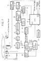
- FIG. 1 is a block diagram showing a representative structure of disk reproducing apparatus embodying the present invention.
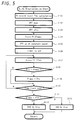
- FIG. 2 is a flowchart showing the operation of the disk reproducing apparatus of FIG. 1.
- FIG. 3 is a continuation of the flowchart of FIG. 2.
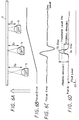
- FIG. 4A is a flowchart elaborating on step S3 of FIG. 2, listing steps for differentiating between a DVD and a CD.
- FIGS. 4B and 4C illustrate a principle behind the DVD/CD discrimination.
- FIG. 5 is a flowchart elaborating on step S3 of FIG. 2, listing steps for differentiating between a DVD DL and a DVD SL.
- FIGS. 6A-6D illustrate operations of pickup 5 and various signals in accordance with the flowchart of FIG. 5 for differentiating between the DVD DL and the DVD SL.
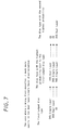
- FIG. 7 is a first embodiment of the decision-making process for estimating a disk type with the highest likelihood of success following the initial erroneous detection of the disk type.
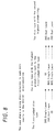
- FIG. 8 is another embodiment of the decision-making process for estimating a disk type with the highest likelihood of success following the initial erroneous detection of the disk type.
- FIG. 1 is a block diagram showing a representative structure of disk reproducing apparatus embodying the present invention.
- a disk 1 (which can be CD, DVD single layer, or DVD double layer, for example) is positioned for rotation at a predetermined speed by a spindle motor 2.
- a tilt sensor 3 directs a beam of light (produced by a built-in LED, for example) at the disk 1 and receives the reflected light beam (acquired by a built-in photodiode) for detecting the tilt (slant) of the disk 1. The detection result is output by the tilt sensor 3 to a CPU 15 as a tilt sum signal.
- a CD discriminating sensor 4 supplies a light beam (produced by a built-in LED) to the disk 1 and determines whether a track pitch on the disk 1 is approximately 1.6 ⁇ m (that is, whether the disk 1 is a CD, since the track pitch of the DVD disk is about 0.74 ⁇ m).
- a CD detection signal (indicating whether the disk is CD), is output by the CD discriminating sensor 4 to the CPU 15.
- a pickup 5 comprising a laser diode and a photodiode, directs a laser beam (produced by the laser diode) onto the disk 1 and receives the reflected light beam from the disk 1 by the photodiode.
- a preamplifier amplifies an electrical signal received from the pickup 5 (that is, the reflected light beam received by the photodiode of the pickup 5 is transformed via a photoelectric conversion to an electrical data reproduction signal) and outputs it to an equalizer 7.
- the equalizer supplies the processed signal to a PLL circuit 8 which derives a clock signal therefrom.
- the derived clock signal together with the data reproduction signal, is provided to a demodulator 9.
- the data reproduction signal is demodulated by the demodulator 9 after being synchronized with the clock signal.
- the output from the demodulator 9 is supplied to a synchronization signal separator circuit 10 and an ECC circuit 13.
- the synchronization signal separator circuit 10 extracts a synchronization signal and outputs it to a CLV (constant linear velocity) controller 11 and an address decoder 12, while the ECC circuit 13 outputs the demodulated data signal to the address decoder 12 after performing an appropriate processing operation to correct errors in the modulated data, if necessary.
- the address decoder 12 On the basis of the synchronization signal supplied from the synchronization separator circuit 10, the address decoder 12 generates an address from the error-corrected data supplied from the ECC circuit 13. As shown in FIG. 1, the decoded address is input to the CPU 15.
- the CLV controller 11 under control of the CPU 15, is operative to control a spindle motor driver 14 for driving the spindle motor 2.
- the spindle motor driver 14 also produces a spindle FG signal corresponding to the rotational frequency of the spindle motor 2.
- the spindle FG signal is provided to the CPU 15.
- the pickup 5 is adapted to reproduce data by using a so-called three beam method (when reproducing data from the CD), and by using one beam method (when reproducing data from the DVD).
- the photodiode for reproducing the data is divided into four representatively named sections A, B, C and D; and a photodiode for tracking the CD is divided into two representatively named sections E and F.
- the preamplifier 6 outputs the individual signals from the photodiodes A through F to a matrix circuit 16.
- the matrix circuit 16 among other things, combines (adds) the signals of the photodiodes A through D, and outputs the added signal to a peak hold circuit 17 as a Pull-In signal.
- the peak hold circuit 17 detects a peak value of the Pull-In signal and outputs the detected peak value to the CPU 15.
- the matrix circuit 16 calculates a so-called diagonal signal as (A + C) - (B + D) from the output signals of the photodiode sections positioned diagonally in the pickup 5, such that a focus error signal is generated. Furthermore, in a case where the disk 1 is CD, the difference (E-F) in the output signals from the photodiode sections E and F is calculated, resulting in a tracking error signal. When the disk 1, however, is DVD, the tracking error signal is produced by a Differential Phase Detection (DPD) method as a function of the diagonal signal and the Pull-In signal.
- DPD Differential Phase Detection
- a servo processor 18 receives the focus error signal and the tracking error signal from the matrix circuit 16, and adjusts these signals appropriately as output to a pickup driver 20.
- the pickup driver 20 (focus servo) is arranged to move the pickup 5 in the focus direction or the tracking direction in accordance with the focus error signal or the tracking error signal, respectively, while also being operative to adjust the pickup 5 in the radial direction of the disk 1.
- the EEPROM 19 stores a PI (sldisk, slmode) level of the Pull-In signal when data from the DVD SL disk is reproduced in the SL mode (a mode where the parameters for the DVD SL disk are set), and a PI (dldisk, dlmode) level of the Pull-In signal when data from the DL disk is reproduced in the DL mode (a mode where the parameters for the DVD DL disk are set).
- PI PI
- step S1 the CPU 15 is programmed to activate the laser diode of the pickup 5 for generating a laser beam. Consequently, the generated laser beam is directed onto the disk 1, wherein the reflected light is received by the photodiode of the pickup 5. Then, the output of the photodiode is supplied to the preamplifier 6.
- step S2 the CPU 15 is operative to control the spindle motor driver 14 (via the CLV controller 11) for driving the spindle motor 2.
- step S3 the CPU 15 performs the processing operation for discriminating the disk 1.
- This processing operation includes the step of distinguishing between the DVD and the CD, and the step of distinguishing between the DVD DL and the DVD SL when the disk 1 is inserted in the reproducing device.
- FIG. 4A The processing operations for discriminating between the DVD and CD are shown in detail in the flowchart in FIG. 4A and in FIGS. 4B and 4C. That is, the flowchart in FIG. 4A illustrates some of the operations included in step S3 of FIG. 2, while FIGS. 4B and 4C show the principle behind the DVD/CD discrimination.
- the incident light is divided into diffracted light beams, namely, a so-called zero order light beam which proceeds in the same direction as the incident light, and other diffracted light beams in divergent directions including so-called +first order light beam, +third order light beam, ..., +higher order light beam, -first order light beam, -second order light beam, ..., -higher order light beam.
- diffracted light beams namely, a so-called zero order light beam which proceeds in the same direction as the incident light
- other diffracted light beams in divergent directions including so-called +first order light beam, +third order light beam, ..., +higher order light beam, -first order light beam, -second order light beam, ..., -higher order light beam.
- the angle divergence from the zero-order light beam depends on a track pitch Pt.
- a track pitch is about 1.6 ⁇ m in the disk 1 (being a CD type)
- a first-order diffracted light beam 1B is returned (reflected) as shown in FIG. 4C.
- the angle ⁇ 1 represents the diffraction angle for the CD.
- a first-order diffracted light beam 1C is returned (reflected) as shown in FIG. 4C.
- the angle ⁇ 2 represents the diffraction angle for the DVD, which is larger than ⁇ 1.
- the type of disk 1 can be identified. Since the angular difference between the diffraction angle ⁇ 1 and the diffraction angle ⁇ 2 is typically about several degrees, the type of disk 1 can be ascertained with great reliability.
- step S91 a representative memory storage labeled "N" for storing the number of times that the below-described detection takes place is initialized to 3.
- step S92 the CD detection signal from the CD discriminating sensor 4 is checked by the CPU 15.
- step S93 after receiving and processing the CD detection signal, the CPU 15 executes appropriate instructions for indicating that disk 1 is CD.
- step S92 if the CPU 15 determines that the information carried by the CD detection signal is not indicative of the CD disk type, the CPU 15 is operative to execute instructions for temporarily assuring that the disk type is DVD. Accordingly, in this case, the process advances to step S94 and the value in N is decreased by one. Then, a determination is made in step S95 whether the value in N is equal to 0. If N does not contain 0, the process returns to step S92 and once again the output from the CD discriminating sensor 4 is checked. It is apparent that a time interval has elapsed by the time the output from the CD discriminating sensor 4 is checked again (that is, when N is less than 3, for example).
- the discriminating sensor 4 receives the light beam reflected from the new area of the disk 1, and performs the detection processing on the newly reproduced data.
- the disk 1 is correctly detected during the second detection (based on the data reproduced from the new position on the disk 1), provided, of course, that the disk type is CD.
- the CPU 15 is programmed to carry out appropriate instructions for the CD disk type.
- step S94 N is equal to 0, the processing in step S96 is carried out such that the disk 1 type is set to DVD. In this case, the details of the processing operation for differentiating between the DVD DL disk and DVD SL disk are shown in the flowchart of FIG. 5.
- the equation (1) will now be explained.
- the SL disk has a larger reflectance value (that is, the reflected light beam intensity is higher) than the DL disk.
- the threshold level PI r1 is used for differentiating between the SL disk and the DL disk based on a difference in the reflectance value.
- a focus error signal (as shown in FIG. 6C) deviates from its zero level as objective lens of the pickup 5 (labeled in the figure as a so-called OPT) is gradually brought closer to the disk 1 (as represented by distances D 0 , D 1 , D 2 in FIG. 6A) in the direction of the arrow (the focus direction) to its optimum position (the distance D 1 in FIG. 6A).
- the pickup 5 movement is realized via the pickup driver 20 outputting a drive voltage as shown in FIG. 6B.
- the Pull-In signal becomes maximum when the focus error signal (FIG. 6C) approximately crosses the zero level.
- the level of the Pull-In (PI) signal is larger for the SL disk than the DL disk in the vicinity of the zero-crossing by the focus error signal, as illustrated in FIG. 6D (that is, PI(sldisk, slmode) is greater than PI(dldisk, slmode)).
- the threshold level Pl r1 is preset to an intermediate value between the Pull-In signal of the SL disk (PI(sldisk, slmode)) and the Pull-In signal of the DL disk (PI(dldisk, slmode)).
- the EEPROM 19 stores the PI(sldisk, slmode) of the Pull-In signal when the data from the DL disk is reproduced in the DL mode (excluding the DC component, a so-called PI ref level), and stores the PI(dldisk, dlmode) of the Pull-In signal when the data from the SL disk is reproduced in the SL mode (also excluding the PI ref level).
- the threshold level PI r1 selected as the approximate intermediate value between the PI[sldisk, slmode) and PI(dldisk, slmode) is adequate for differentiating between the two.
- the Pull-In signal values may vary as a function of the laser power or its gain, or may depend on whether the focus servo is turned on in the reproducing device.
- Let a ratio of LP SL and LP DL be as follows: LP SL : LP DL a : b where LP SL is an SL mode parameter and LP DL is a DL mode parameter relating to the laser power.
- G SL is an SL mode parameter
- G DL is a DL mode parameter relating to the laser gain.
- PI focusoff is a Pull-In signal level when the focus servo is turned off
- PI focuson is a Pull-In signal level when the focus servo is turned on in the reproducing device.
- PI(dldisk, slmode) (PI(dldisk, dlmode) - PIref) x (a/b) x (c/d) x (e/f) + PIref
- PI(sldisk, slmode) (PI(sldisk, slmode) - Plref) x (e/f) + PIref
- the pickup 5 (OPT) is initially moved down (that is, in a direction away from the disk 1) and then stopped by the pickup driver 20 in steps S102 and S103, respectively.
- the Pull-In signal level is stored in a memory storage labeled "PI max " in step S104, thereby initializing the PI max .
- the pickup driver 20 starts moving the pickup 5 (OPT) up (that is, toward the disk 1) in step S105; and a timer is set for a predetermined time interval in step S106.
- the CPU 15 stores the Pull-In signal level in a memory storage representatively labeled "PI x ", where "x" indicates the sample number.
- step S108 the values in the PI max and PI x are compared; and if PI x is greater than PI max then the value in PI max is replaced with the current value of PI x in step S109.
- steps S108 and S109 is repeated until the predetermined time interval (as checked by the timer in step S110) is exceeded.
- the maximum level of the Pull-In signal is obtained and stored in PI max .
- the maximum Pull-In signal level (that is, the value in PI max ) is compared (in step S111) with the reference Pull-In signal level stored in PI r1 .
- the disk type is set as DVD SL (step S112); while, if the maximum Pull-In signal level is smaller than the reference Pull-In signal level (that is, PI max ⁇ PI r1 ), then the disk type is set as DVD DL (step S113), as graphically illustrated in FIG. 6D.
- Disk Type Retry stores a count value for the number of times the disk type is attempted to be ascertained accurately in a start-up condition.
- the CPU 15 performs various operations for setting system parameters according to the disk discrimination result in step S3. That is, in step S3, it is determined whether the disk 1 type is DVD SL, DVD DL, or CD, so that according to the result of this determination, the power of the laser diode of the pickup 5, the gain of the system and the like are set accordingly, as required for this particular disk type.
- step S6 the CPU 15 initializes a memory storage labeled "Focus Retry". Focus Retry maintains a count value for the number of times that the focus servo is activated (turned on) during the apparatus start-up.
- step S7 a timer is set by the CPU 15 which also controls the servo processor 18 to turn on the focus servo in step S8.
- the output signals from the photodiode sections A-D are calculated in the matrix circuit 16, and the focus error signal is generated based on these output signals. Then, the focus error signal is supplied to the servo processor 18 for controlling the pickup driver 20 (as a function of the focus error signal) which adjusts the pickup 5 in the focus direction, as illustrated in FIGS. 1 and 6(A).
- step S9 it is determined in step S9 whether the focus servo is locked (correctly set). If it is not, the process then proceeds to step S10 where the CPU 15 is operative to execute the necessary instructions for ascertaining whether the timer (as set in step S7) has expired (exceeded a predetermined time interval). If the timer has not yet expired, the process returns to step S9 and steps S9 and S10 are repeated.
- step S9 When the focus servo is not. locked (as determined in step S9) and the timer exceeded the predetermined time interval (as determined in step S10), the process advances to step S11 where the CPU 15 controls the servo processor 18 to turn off the focus servo.
- step S12 the count value of Focus Retry (initially set to 0 in step S6) is incremented by one.
- step S13 it is determined, in step S13, whether the count value of Focus Retry is equal to 3.
- the CPU 15 controls the servo processor 18 to move the pickup 5 in the direction of the outer circumference (periphery) of the disk 1.
- step S8 the process returns to step 57 such that the timer is set once more, and the focus servo is turned on in step S8.
- steps S9, S10 the locking operation of the focus servo is attempted and waited until the timer exceeds the predetermined time interval if the focus is not established in the apparatus. In a case where the focus servo is not locked, the focus servo is turned off again in step S11, and the count value of Focus Retry is increased by one.
- the operation of turning on the focus servo is performed three times when the focus servo is not locked by the time the timer expires during each try. If the third attempt cannot produce the locked focus servo, the "YES" decision is made in step S13, and step S15 is carried out for estimating, with high probability, the disk type.
- the steps as shown in the flowchart of FIG. 4A are carried out for processing the output signal (the CD detection signal) of the CD discriminating sensor 4, so that a differentiation between a CD or a DVD can be made.
- the disk 1 type is DVD DL cr DVD SL.
- the differentiation between the DL disk and the SL disk has a higher probability of being erroneous.
- an estimation procedure as shown in FIG. 7, is performed in step S15.
- the disk type in the reproducing device has been determined to be DVD (in accordance with the operation in FiG. 4A) and then SL (in accordance with the operation of FIG. 5), the appropriate parameters corresponding to the determined disk type (DVD SL) are set. Then, an attempt to lock the focus servo is carried out. When three attempts are unsuccessful (that is, the focus servo cannot be locked three times), it is decided that the previous determination on the disk type was erroneous. It, therefore, follows that the disk 1 type has to be either DVD DL or CD in the exemplary embodiment. In this situation, the determination of whether the disk type is DVD DL or CD is based on a likelihood of making an erroneous decision between these two disk types.
- the erroneous decision is more likely to be made in the DL/SL determination (FIG. 5) than in the DVD/CD determination (FIG. 4A).
- the information provided by the CD detection signal from the CD discriminating sensor 4 is considered to be reliable.
- the CPU 15 sets the appropriate parameters corresponding to the DL disk based on a decision that the DVD DL has the highest likelihood of being the correct disk type after the first-made incorrect decision.
- the disk 1 is determined to be CD.
- the appropriate parameters are then set for the CD as the disk type with the second highest probability.
- the above-described decision-making process based on the likelihood of the erroneous determination for the representative disk types DVD SL, DVD DL, and CD is illustrated in a first row (from left to right) in FIG. 7.
- the disk type was initially determined as DVD SL.
- a second row in FIG. 7 illustrates the decision-making process when the initial incorrect decision on the disk type has been DVD DL.
- the probability is high that the disk type is DVD SL (because of high reliability of the detection by the CD discriminating sensor 4, as mentioned above). Accordingly, the next disk type is selected as DVD SL (with the CPU 15 setting the corresponding parameters), while the CD is selected last if the focus servo cannot be locked for the DVD SL.
- the difference in the reflectance values between the DVD DL and CD is greater than between the DVD SL and CD.
- the fact that the DVD DL is erroneously considered to be CD (or, conversely, the CD is erroneously considered to be DVD DL) means that the decisions based on the track pitch and on the reflectance values both have been incorrect. Since the probability that these two decisions had been erroneous is small, when the disk type has been determined to be CD incorrectly, it is more likely that the disk type discrimination based on the reflectance value is correct.
- the second most likely disk type in this representative embodiment is DVD SL, and the next most likely disk type is DVD DL.
- FIG. 8 shows a decision-making order for the disk type discrimination when it is more likely to err between the DVD and CD disk types, as occurs in some reproducing devices.
- a probability that the disk type is CD which has a reflectance value near the reflectance value of the DVD SL, is high.
- the disk type in the reproducing device is DVD DL
- the disk type discrimination based on the track pitch (using the CD discriminating sensor 4) and/or the discrimination based on the reflectance values are considered to be erroneous. Since the probability that only one of them is wrong is higher than the probability that both are wrong, CD is given a preference as the disk type. Then, when it is determined that the disk type is not CD, the remaining disk type is set as DVD DL. This operation is illustrated in a first row of FIG 8.
- the disk type is either DVD SL or CD. If the disk type is CD, it means that not only the DVD/CD discrimination is in error but also the DL/SL discrimination using the reflectance values has been made incorrectly. Accordingly, based on a likelihood that one disk type discrimination operation is correct (between the DVD and CD) instead of both being incorrect, the parameters in the reproducing device are set for the DVD SL. Then, if it is not DVD SL, then the disk type is determined to be CD.
- the probability that the disk type is DVD SL, having the reflectance value closer to the CD than to DVD SL, is high. Accordingly, in that case, it is decided that the disk type is not CD but DVD SL. Thereafter, if the disk type is not DVD SL (because the focus servo cannot be set), the parameters for the DVD DL are established.
- step S16 in FIG. 2 the value held in Disk Type Retry is increased by one such that in the present case it becomes 2.
- step S17 whether the updated value is less than 3 is determined. In the present case, since the value is less than 3, the process returns to step S5 and the processing to set parameters corresponding to the disk type as estimated in step S15 is performed once more. Then, similar to the above, the focus servo is turned on in step S8 and whether it is locked is checked in step S9.
- step S18 If the focus servo cannot be locked after the parameters corresponding to each disk type have been tried three times, a decision is made in step S18 that the disk in the reproducing device is unusable.
- step S9 in a case of the focus servo being locked, the process proceeds to step S19 (FIG. 3) where a memory storage representatively labelcd "CLV Retry" is initialized.
- CLV Retry stores a counter for the number of times the CLV servo is turned on.
- step S20 the CPU 15 controls the CLV controller 11 to turn on a rough servo for operating the spindle motor 2.
- step S21 the CPU 15 controls the servo processor 18 to turn on a tracking servo, and also controls the CLV controller 11 to turn on the CLV servo in place of the rough servo in step S22.
- step S23 the CPU 15 sets a timer, and in step S24 it is determined whether the CLV servo is locked. When the CLV servo is not locked, it is determined in step S25 whether the timer has exceeded the predetermined time interval. If not, the operation in step S24 continues to be carried out.
- steps S24, S25 are repeated until the timer expires while the CLV servo is not in the locked state.
- the process then advances to step S26 where the CPU 15 turns on the rough servo again in place of the CLV servo.
- step S27 the CPU 15 increments the count value held in CLV Retry in step S28.
- step S29 whether the updated count value is equal to 3 is checked. If so, the process advances to step S30 where the CPU 15 moves the pickup 5 to the outer periphery and changes the locking position of the CLV servo to a different position. Then, the process returns to step S20 and the corresponding steps are repeated as described above.
- step S31 If the CLV servo cannot be locked after three attempts within the specified time interval, it is checked in step S31 whether the count value in Disk Type Retry is less than 3. If so, neither the focus servo nor the CLV servo can be locked after the parameters corresponding to each of the three disk types have been consecutively set. Accordingly, in that case, the process advances to step S36, and the disk is considered to be unusable.
- step S32 the operations for estimating and setting the disk type are carried out based on the likelihood of the erroneous disk type discrimination.
- the operations are the same as in step S15 described above with reference to FIGS. 7 and 8.
- step S33 Disk Type Retry is increased by one, and the focus servo is turned off in step S34.
- step S35 the CPU 15 moves the pickup 5 to its home position.
- step S5 the process returns to step S5 (FIG. 2) and the operations to set the parameters corresponding to the disk type estimated in step S32, as well as to lock the focus servo, are performed as described above with reference to FIG. 2. That is, when the CLV servo cannot be locked, even if the focus servo has been locked, it is considered that the disk type has been determined erroneously, and accordingly the operations to lock the focus servo and the CLV servo are performed again.
- step S37 the CPU 15 controls the servo processor 18 to turn on the sled servo.
- step S38 the addresses received from the address decoder 12 are stored by the CPU 15 which confirms the continuity of the addresses in step S39. Finally, the disk 1 is reproduced in step S40.
- DVD and CD disk types have been representatively described. It is understood, of course, that other disk types (as well as a different quantity thereof) can be used for reproducing data.
Abstract
Description
Claims (21)
- Apparatus for reproducing data from one of a number of disks, each disk being of a predetermined type, comprising:reproducing means for reproducing data from a disk;detecting means for performing detection operation to detect the disk type such that said data can be reproduced from said disk correctly; andsetting means for setting said reproducing means to a predetermined condition corresponding to another disk type when the detected disk type has been detected erroneously, said predetermined condition being selected, as a function of said detection operation, from at least two other predetermined conditions.
- The apparatus according to claim 1, further comprising means for performing a differentiating operation to differentiate between a compact disk and a digital video disk such that said detection operation comprises said differentiating operation.
- The apparatus according to claim 1, further comprising means for performing a differentiating operation to differentiate between a first digital video disk having said data recorded on two layers and a second digital video disk having said data recorded on one layer such that said detection operation comprises said differentiating operation.
- The apparatus according to claim 1, wherein said setting means sets said reproducing means to said predetermined condition by establishing a number of predetermined parameters such that said data can be reproduced from said disk correctly.
- The apparatus according to claim 4, wherein said predetermined parameters include one of a beam focus and a disk velocity.
- The apparatus according to claim 1, wherein said setting means sets said reproducing means to said predetermined condition when said reproducing means cannot reproduce said data from the detected disk.
- The apparatus according to claim 1, wherein said setting means sets said reproducing means to said predetermined condition when said reproducing means unsuccessfully attempts to reproduce said data from the detected disk a predetermined number of times.
- The apparatus according to claim 1, further comprising means for establishing said disk as unusable when said reproducing means unsuccessfully attempts to reproduce said data from said disk a predetermined number of times for each respective disk type.
- The apparatus according to claim 1, wherein said each disk has a different data format.
- The apparatus according to claim 1, wherein said each disk has said data recorded on a different number of layers.
- The apparatus according to cLaim 1, wherein said each disk has a different data recording density.
- A device for determining a type of a disk from which data can be reproduced, comprising:means for detecting the disk type such that said data can be reproduced from said disk correctly; andmeans for selecting a second disk type for said disk when a first disk type has been detected erroneously, said selection being based on a probability of said disk being of said second disk type following the erroneous detection of said disk as being of said first disk type.
- The device according to claim 12, wherein said disk is one of a compact disk, a first digital video disk having said data recorded on one layer, and a second digital video disk having said data recorded on at least two layers.
- A method for determining a type of a disk from which data can be reproduced, comprising the steps of:detecting the disk type such that said data can be reproduced from said disk correctly; andselecting a second disk type for said disk when a first disk type has been detected erroneously, said selection being based on a probability of said disk being of said second disk type following the erroneous detection of said disk as being of said first disk type.
- The method according to claim 14, further comprising differentiating between a compact disk and a digital video disk such that said detecting step comprises said differentiating step.
- The method according to claim 14, further comprising differentiating between a first digital video disk having said data recorded on two layers and a second digital video disk having said data recorded on one layer such that said detecting step comprises said differentiating step.
- The method according to claim 14, further comprising establishing a number of predetermined parameters for said first and second disk types such that said data can be reproduced from said disk correctly.
- The method according to claim 17, wherein said predetermined parameters include one of a beam focus and a disk velocity.
- The method according to claim 14, wherein said second disk type is selected when said data cannot be reproduced from said disk.
- The method according to claim 14, wherein said second disk type is selected after unsuccessfully actempting to reproduce said data from said disk a predetermined number of times.
- The method according to claim 14, further comprising establishing said disk as unusable after unsuccessfully attempting to reproduce said data from said disk a predetermined number of times for said first and second disk types.
Applications Claiming Priority (2)
| Application Number | Priority Date | Filing Date | Title |
|---|---|---|---|
| JP28356896A JP3619625B2 (en) | 1996-10-25 | 1996-10-25 | Disk discriminating apparatus and method |
| JP283568/96 | 1996-10-25 |
Publications (3)
| Publication Number | Publication Date |
|---|---|
| EP0838818A2 true EP0838818A2 (en) | 1998-04-29 |
| EP0838818A3 EP0838818A3 (en) | 1999-01-20 |
| EP0838818B1 EP0838818B1 (en) | 2008-05-07 |
Family
ID=17667218
Family Applications (1)
| Application Number | Title | Priority Date | Filing Date |
|---|---|---|---|
| EP97308382A Expired - Lifetime EP0838818B1 (en) | 1996-10-25 | 1997-10-22 | Determination of disk types and reproducing data from disks |
Country Status (11)
| Country | Link |
|---|---|
| US (1) | US6072757A (en) |
| EP (1) | EP0838818B1 (en) |
| JP (1) | JP3619625B2 (en) |
| KR (1) | KR100508192B1 (en) |
| CN (1) | CN1129132C (en) |
| AU (1) | AU724784B2 (en) |
| DE (1) | DE69738663D1 (en) |
| ES (1) | ES2304790T3 (en) |
| ID (1) | ID18825A (en) |
| MY (1) | MY120707A (en) |
| TW (1) | TW394930B (en) |
Cited By (4)
| Publication number | Priority date | Publication date | Assignee | Title |
|---|---|---|---|---|
| EP0910079A1 (en) * | 1997-10-15 | 1999-04-21 | Mitsumi Electric Company Ltd. | Optical disc drive and method of discriminating optical discs |
| EP1187111A2 (en) * | 2000-08-24 | 2002-03-13 | Pioneer Corporation | Method of discriminating disk type and reproducing apparatus thereof |
| EP1477980A1 (en) * | 2003-05-13 | 2004-11-17 | Pioneer Corporation | Recording medium identification apparatus, information reproduction apparatus and information recording apparatus |
| EP1607965A2 (en) | 2004-06-18 | 2005-12-21 | Samsung Electronics Co., Ltd. | Method and device for changing the play mode of a medium |
Families Citing this family (13)
| Publication number | Priority date | Publication date | Assignee | Title |
|---|---|---|---|---|
| KR100272493B1 (en) * | 1997-08-30 | 2000-11-15 | 윤종용 | Apparatus of processing data for digital video disk and compact disk |
| DE19755741A1 (en) * | 1997-12-16 | 1999-06-17 | Thomson Brandt Gmbh | CD player for CD-like recording formats |
| US6601046B1 (en) * | 1999-03-25 | 2003-07-29 | Koninklijke Philips Electronics N.V. | Usage dependent ticket to protect copy-protected material |
| JP3586403B2 (en) * | 2000-01-13 | 2004-11-10 | パイオニア株式会社 | Recording medium reproducing method and apparatus |
| KR100722589B1 (en) * | 2000-12-29 | 2007-05-28 | 엘지전자 주식회사 | Method for interfacing a combo drive system with host |
| US6940794B2 (en) * | 2001-08-03 | 2005-09-06 | Matsushita Electric Industrial Co., Ltd. | Information recording/reproducing apparatus that determines the number of recording layers of an information recording medium |
| JP4342930B2 (en) * | 2003-12-25 | 2009-10-14 | 株式会社東芝 | Optical disc apparatus, control method therefor, and recording medium |
| JP2006114100A (en) * | 2004-10-13 | 2006-04-27 | Teac Corp | Optical disk device and starting method of optical disk |
| US20080219111A1 (en) * | 2005-09-09 | 2008-09-11 | Koninklijke Philips Electronics, N.V. | Drive and Method of Operating the Drive and an Optical Data Carrier Therefore |
| CN101000785B (en) * | 2006-01-13 | 2010-05-12 | 鸿富锦精密工业(深圳)有限公司 | Disc kind recognition method and system |
| JP4902589B2 (en) * | 2008-04-18 | 2012-03-21 | 株式会社日立製作所 | Optical disc apparatus and disc discrimination method |
| JP2010118113A (en) * | 2008-11-13 | 2010-05-27 | Sony Corp | Disk driving device and disk discrimination method |
| US8711664B2 (en) * | 2010-06-21 | 2014-04-29 | Mediatek Inc. | Method of controlling mechanical mechanisms of optical storage apparatus for peak power/current reduction, and related optical storage apparatus and machine-readable medium |
Citations (5)
| Publication number | Priority date | Publication date | Assignee | Title |
|---|---|---|---|---|
| JPS60264173A (en) * | 1984-06-13 | 1985-12-27 | Hitachi Ltd | System for identifying different kind of disc in video disc player |
| US5153879A (en) * | 1989-03-23 | 1992-10-06 | Mitsubishi Denki Kabushiki Kaisha | Optical recording system |
| US5289451A (en) * | 1984-11-29 | 1994-02-22 | Canon Kabushiki Kaisha | Optical information recording/reproduction apparatus including means for detecting the type of recording medium |
| EP0691652A1 (en) * | 1994-07-04 | 1996-01-10 | Sony Corporation | Apparatus for replaying recording medium |
| EP0724263A2 (en) * | 1995-01-30 | 1996-07-31 | Sony Corporation | Disc-shaped recording medium, recording apparatus and reproducing apparatus |
Family Cites Families (2)
| Publication number | Priority date | Publication date | Assignee | Title |
|---|---|---|---|---|
| JPS5977606A (en) * | 1982-10-25 | 1984-05-04 | Sony Corp | Reproducing device of digital disc |
| JPH08221890A (en) * | 1995-02-17 | 1996-08-30 | Hitachi Ltd | Optical reproducing device |
-
1996
- 1996-10-25 JP JP28356896A patent/JP3619625B2/en not_active Expired - Fee Related
-
1997
- 1997-10-21 US US08/955,847 patent/US6072757A/en not_active Expired - Lifetime
- 1997-10-22 DE DE69738663T patent/DE69738663D1/en not_active Expired - Lifetime
- 1997-10-22 TW TW086115631A patent/TW394930B/en not_active IP Right Cessation
- 1997-10-22 ES ES97308382T patent/ES2304790T3/en not_active Expired - Lifetime
- 1997-10-22 EP EP97308382A patent/EP0838818B1/en not_active Expired - Lifetime
- 1997-10-23 MY MYPI97005002A patent/MY120707A/en unknown
- 1997-10-23 ID IDP973513A patent/ID18825A/en unknown
- 1997-10-24 AU AU42846/97A patent/AU724784B2/en not_active Ceased
- 1997-10-25 CN CN97120812A patent/CN1129132C/en not_active Expired - Fee Related
- 1997-10-25 KR KR1019970055880A patent/KR100508192B1/en not_active IP Right Cessation
Patent Citations (5)
| Publication number | Priority date | Publication date | Assignee | Title |
|---|---|---|---|---|
| JPS60264173A (en) * | 1984-06-13 | 1985-12-27 | Hitachi Ltd | System for identifying different kind of disc in video disc player |
| US5289451A (en) * | 1984-11-29 | 1994-02-22 | Canon Kabushiki Kaisha | Optical information recording/reproduction apparatus including means for detecting the type of recording medium |
| US5153879A (en) * | 1989-03-23 | 1992-10-06 | Mitsubishi Denki Kabushiki Kaisha | Optical recording system |
| EP0691652A1 (en) * | 1994-07-04 | 1996-01-10 | Sony Corporation | Apparatus for replaying recording medium |
| EP0724263A2 (en) * | 1995-01-30 | 1996-07-31 | Sony Corporation | Disc-shaped recording medium, recording apparatus and reproducing apparatus |
Non-Patent Citations (1)
| Title |
|---|
| PATENT ABSTRACTS OF JAPAN vol. 010, no. 137 (E-405), 21 May 1986 & JP 60 264173 A (HITACHI SEISAKUSHO KK), 27 December 1985 * |
Cited By (8)
| Publication number | Priority date | Publication date | Assignee | Title |
|---|---|---|---|---|
| EP0910079A1 (en) * | 1997-10-15 | 1999-04-21 | Mitsumi Electric Company Ltd. | Optical disc drive and method of discriminating optical discs |
| US6249499B1 (en) | 1997-10-15 | 2001-06-19 | Mitsumi Electric Company | Optical disc drive and method of discriminating optical discs |
| EP1187111A2 (en) * | 2000-08-24 | 2002-03-13 | Pioneer Corporation | Method of discriminating disk type and reproducing apparatus thereof |
| EP1187111A3 (en) * | 2000-08-24 | 2003-03-19 | Pioneer Corporation | Method of discriminating disk type and reproducing apparatus thereof |
| US6643238B2 (en) | 2000-08-24 | 2003-11-04 | Pioneer Corporation | Method of discriminating disk type and reproducing apparatus thereof |
| EP1477980A1 (en) * | 2003-05-13 | 2004-11-17 | Pioneer Corporation | Recording medium identification apparatus, information reproduction apparatus and information recording apparatus |
| EP1607965A2 (en) | 2004-06-18 | 2005-12-21 | Samsung Electronics Co., Ltd. | Method and device for changing the play mode of a medium |
| US7580328B2 (en) | 2004-06-18 | 2009-08-25 | Samsung Electronics Co., Ltd. | Method, medium, and device changing a play mode |
Also Published As
| Publication number | Publication date |
|---|---|
| JPH10134497A (en) | 1998-05-22 |
| JP3619625B2 (en) | 2005-02-09 |
| MY120707A (en) | 2005-11-30 |
| ES2304790T3 (en) | 2008-10-16 |
| CN1198571A (en) | 1998-11-11 |
| MX9708158A (en) | 1998-06-30 |
| CN1129132C (en) | 2003-11-26 |
| KR100508192B1 (en) | 2005-11-08 |
| DE69738663D1 (en) | 2008-06-19 |
| EP0838818A3 (en) | 1999-01-20 |
| TW394930B (en) | 2000-06-21 |
| ID18825A (en) | 1998-05-14 |
| EP0838818B1 (en) | 2008-05-07 |
| KR19980033269A (en) | 1998-07-25 |
| US6072757A (en) | 2000-06-06 |
| AU4284697A (en) | 1998-04-30 |
| AU724784B2 (en) | 2000-09-28 |
Similar Documents
| Publication | Publication Date | Title |
|---|---|---|
| EP0838818B1 (en) | Determination of disk types and reproducing data from disks | |
| US6853609B2 (en) | Optical disc drive | |
| US6868051B2 (en) | Optical disk drive, and method for identifying optical disks mounted thereto | |
| US6747922B2 (en) | Track-jump controlling apparatus and method | |
| EP1446799B1 (en) | Appliance for recording or playing back information having means for detecting or moving the scanning location on a disc with a wobble track | |
| JP3753267B2 (en) | Disc recording / reproducing apparatus and method | |
| US20040090894A1 (en) | Method and apparatus for identifying disc type | |
| KR100430249B1 (en) | Apparatus for and method of determining information record medium | |
| JP2003109232A (en) | Servo circuit and servo method used for optical disk playback device | |
| JP2003217135A (en) | Optical disk drive, method for discriminating disk thereof and method for discriminating abnormality of chucking | |
| JP2000090554A (en) | Method and device for discriminating optical disk | |
| WO2001065550A1 (en) | Optical disc apparatus | |
| JP2901769B2 (en) | Optical information recording / reproducing device | |
| US7274631B2 (en) | Optical-disc driving apparatus, optical-disc driving method, storage medium, and program | |
| EP1548731B1 (en) | Optical disk apparatus, method for controlling the same, and recording medium | |
| US5974014A (en) | Disc reproducing apparatus and method | |
| US20030231565A1 (en) | Disk reproducing apparatus and disk type identifying method | |
| KR20000026832A (en) | Method for controlling tilt | |
| MXPA97008158A (en) | Apparatus and method for determining a type of disc before reproducing the data of the di | |
| US6633025B2 (en) | Method and apparatus for detecting and compensating inclination of objective lens | |
| KR100595497B1 (en) | Digital Information Storage Media and Its Prevention Methods | |
| US20070115793A1 (en) | Optical disk reproducing device | |
| JP4240104B2 (en) | Optical disk device | |
| JP5076846B2 (en) | Optical disk device | |
| CN101197152A (en) | Optical disc apparatus and optical disc recording and reproducing method |
Legal Events
| Date | Code | Title | Description |
|---|---|---|---|
| PUAI | Public reference made under article 153(3) epc to a published international application that has entered the european phase |
Free format text: ORIGINAL CODE: 0009012 |
|
| AK | Designated contracting states |
Kind code of ref document: A2 Designated state(s): DE ES FR GB IT NL |
|
| PUAL | Search report despatched |
Free format text: ORIGINAL CODE: 0009013 |
|
| AK | Designated contracting states |
Kind code of ref document: A3 Designated state(s): AT BE CH DE DK ES FI FR GB GR IE IT LI LU MC NL PT SE |
|
| 17P | Request for examination filed |
Effective date: 19990705 |
|
| AKX | Designation fees paid |
Free format text: DE ES FR GB IT NL |
|
| 17Q | First examination report despatched |
Effective date: 19991101 |
|
| GRAP | Despatch of communication of intention to grant a patent |
Free format text: ORIGINAL CODE: EPIDOSNIGR1 |
|
| GRAS | Grant fee paid |
Free format text: ORIGINAL CODE: EPIDOSNIGR3 |
|
| GRAA | (expected) grant |
Free format text: ORIGINAL CODE: 0009210 |
|
| AK | Designated contracting states |
Kind code of ref document: B1 Designated state(s): DE ES FR GB IT NL |
|
| REG | Reference to a national code |
Ref country code: GB Ref legal event code: FG4D |
|
| REF | Corresponds to: |
Ref document number: 69738663 Country of ref document: DE Date of ref document: 20080619 Kind code of ref document: P |
|
| REG | Reference to a national code |
Ref country code: ES Ref legal event code: FG2A Ref document number: 2304790 Country of ref document: ES Kind code of ref document: T3 |
|
| PLBE | No opposition filed within time limit |
Free format text: ORIGINAL CODE: 0009261 |
|
| STAA | Information on the status of an ep patent application or granted ep patent |
Free format text: STATUS: NO OPPOSITION FILED WITHIN TIME LIMIT |
|
| 26N | No opposition filed |
Effective date: 20090210 |
|
| REG | Reference to a national code |
Ref country code: GB Ref legal event code: 746 Effective date: 20120703 |
|
| REG | Reference to a national code |
Ref country code: DE Ref legal event code: R084 Ref document number: 69738663 Country of ref document: DE Effective date: 20120614 |
|
| PGFP | Annual fee paid to national office [announced via postgrant information from national office to epo] |
Ref country code: ES Payment date: 20141020 Year of fee payment: 18 Ref country code: GB Payment date: 20141021 Year of fee payment: 18 Ref country code: DE Payment date: 20141022 Year of fee payment: 18 Ref country code: FR Payment date: 20141022 Year of fee payment: 18 |
|
| PGFP | Annual fee paid to national office [announced via postgrant information from national office to epo] |
Ref country code: NL Payment date: 20141021 Year of fee payment: 18 |
|
| PGFP | Annual fee paid to national office [announced via postgrant information from national office to epo] |
Ref country code: IT Payment date: 20141030 Year of fee payment: 18 |
|
| REG | Reference to a national code |
Ref country code: DE Ref legal event code: R119 Ref document number: 69738663 Country of ref document: DE |
|
| GBPC | Gb: european patent ceased through non-payment of renewal fee |
Effective date: 20151022 |
|
| REG | Reference to a national code |
Ref country code: NL Ref legal event code: MM Effective date: 20151101 |
|
| PG25 | Lapsed in a contracting state [announced via postgrant information from national office to epo] |
Ref country code: IT Free format text: LAPSE BECAUSE OF NON-PAYMENT OF DUE FEES Effective date: 20151022 Ref country code: DE Free format text: LAPSE BECAUSE OF NON-PAYMENT OF DUE FEES Effective date: 20160503 Ref country code: GB Free format text: LAPSE BECAUSE OF NON-PAYMENT OF DUE FEES Effective date: 20151022 |
|
| REG | Reference to a national code |
Ref country code: FR Ref legal event code: ST Effective date: 20160630 |
|
| PG25 | Lapsed in a contracting state [announced via postgrant information from national office to epo] |
Ref country code: NL Free format text: LAPSE BECAUSE OF NON-PAYMENT OF DUE FEES Effective date: 20151101 Ref country code: FR Free format text: LAPSE BECAUSE OF NON-PAYMENT OF DUE FEES Effective date: 20151102 |
|
| REG | Reference to a national code |
Ref country code: ES Ref legal event code: FD2A Effective date: 20161125 |
|
| PG25 | Lapsed in a contracting state [announced via postgrant information from national office to epo] |
Ref country code: ES Free format text: LAPSE BECAUSE OF NON-PAYMENT OF DUE FEES Effective date: 20151023 |