JP3619625B2 - Disk discriminating apparatus and method - Google Patents
Disk discriminating apparatus and method Download PDFInfo
- Publication number
- JP3619625B2 JP3619625B2 JP28356896A JP28356896A JP3619625B2 JP 3619625 B2 JP3619625 B2 JP 3619625B2 JP 28356896 A JP28356896 A JP 28356896A JP 28356896 A JP28356896 A JP 28356896A JP 3619625 B2 JP3619625 B2 JP 3619625B2
- Authority
- JP
- Japan
- Prior art keywords
- disc
- discriminating
- disk
- discs
- controlled
- Prior art date
- Legal status (The legal status is an assumption and is not a legal conclusion. Google has not performed a legal analysis and makes no representation as to the accuracy of the status listed.)
- Expired - Fee Related
Links
Images


Classifications
-
- G—PHYSICS
- G11—INFORMATION STORAGE
- G11B—INFORMATION STORAGE BASED ON RELATIVE MOVEMENT BETWEEN RECORD CARRIER AND TRANSDUCER
- G11B19/00—Driving, starting, stopping record carriers not specifically of filamentary or web form, or of supports therefor; Control thereof; Control of operating function ; Driving both disc and head
- G11B19/02—Control of operating function, e.g. switching from recording to reproducing
- G11B19/12—Control of operating function, e.g. switching from recording to reproducing by sensing distinguishing features of or on records, e.g. diameter end mark
- G11B19/122—Control of operating function, e.g. switching from recording to reproducing by sensing distinguishing features of or on records, e.g. diameter end mark involving the detection of an identification or authentication mark
-
- G—PHYSICS
- G11—INFORMATION STORAGE
- G11B—INFORMATION STORAGE BASED ON RELATIVE MOVEMENT BETWEEN RECORD CARRIER AND TRANSDUCER
- G11B19/00—Driving, starting, stopping record carriers not specifically of filamentary or web form, or of supports therefor; Control thereof; Control of operating function ; Driving both disc and head
- G11B19/02—Control of operating function, e.g. switching from recording to reproducing
- G11B19/12—Control of operating function, e.g. switching from recording to reproducing by sensing distinguishing features of or on records, e.g. diameter end mark
- G11B19/128—Control of operating function, e.g. switching from recording to reproducing by sensing distinguishing features of or on records, e.g. diameter end mark involving the detection of track pitch or recording density
-
- G—PHYSICS
- G11—INFORMATION STORAGE
- G11B—INFORMATION STORAGE BASED ON RELATIVE MOVEMENT BETWEEN RECORD CARRIER AND TRANSDUCER
- G11B20/00—Signal processing not specific to the method of recording or reproducing; Circuits therefor
- G11B20/10—Digital recording or reproducing
- G11B20/12—Formatting, e.g. arrangement of data block or words on the record carriers
- G11B20/1217—Formatting, e.g. arrangement of data block or words on the record carriers on discs
-
- G—PHYSICS
- G11—INFORMATION STORAGE
- G11B—INFORMATION STORAGE BASED ON RELATIVE MOVEMENT BETWEEN RECORD CARRIER AND TRANSDUCER
- G11B7/00—Recording or reproducing by optical means, e.g. recording using a thermal beam of optical radiation by modifying optical properties or the physical structure, reproducing using an optical beam at lower power by sensing optical properties; Record carriers therefor
- G11B7/004—Recording, reproducing or erasing methods; Read, write or erase circuits therefor
- G11B7/005—Reproducing
-
- G—PHYSICS
- G11—INFORMATION STORAGE
- G11B—INFORMATION STORAGE BASED ON RELATIVE MOVEMENT BETWEEN RECORD CARRIER AND TRANSDUCER
- G11B2220/00—Record carriers by type
- G11B2220/20—Disc-shaped record carriers
- G11B2220/23—Disc-shaped record carriers characterised in that the disc has a specific layer structure
-
- G—PHYSICS
- G11—INFORMATION STORAGE
- G11B—INFORMATION STORAGE BASED ON RELATIVE MOVEMENT BETWEEN RECORD CARRIER AND TRANSDUCER
- G11B2220/00—Record carriers by type
- G11B2220/20—Disc-shaped record carriers
- G11B2220/25—Disc-shaped record carriers characterised in that the disc is based on a specific recording technology
- G11B2220/2537—Optical discs
- G11B2220/2545—CDs
-
- G—PHYSICS
- G11—INFORMATION STORAGE
- G11B—INFORMATION STORAGE BASED ON RELATIVE MOVEMENT BETWEEN RECORD CARRIER AND TRANSDUCER
- G11B2220/00—Record carriers by type
- G11B2220/20—Disc-shaped record carriers
- G11B2220/25—Disc-shaped record carriers characterised in that the disc is based on a specific recording technology
- G11B2220/2537—Optical discs
- G11B2220/2562—DVDs [digital versatile discs]; Digital video discs; MMCDs; HDCDs
-
- G—PHYSICS
- G11—INFORMATION STORAGE
- G11B—INFORMATION STORAGE BASED ON RELATIVE MOVEMENT BETWEEN RECORD CARRIER AND TRANSDUCER
- G11B2220/00—Record carriers by type
- G11B2220/40—Combinations of multiple record carriers
Description
【0001】
【発明の属する技術分野】
本発明は、ディスク判別装置および方法に関し、特に、ディスクの種類を迅速かつ正確に判別することができるようにしたディスク判別装置および方法に関する。
【0002】
【従来の技術】
最近、DVD(Digital Varsatile Disc)が規格化され、普及しつつある。このDVDには、情報記録層が1層のSingle Layer Disc(SLディスク)と、情報記録層が2個形成されているDual Layer Disc(DLディスク)が規定されている。DVDに対して、データを記録または再生する装置において、CD(Compact Disc)も再生することができるようにするものとすると、合計3種類のディスクが装着されるので、そのいずれが装着されたのかを判別する必要がある。
【0003】
【発明が解決しようとする課題】
DVDには、コントロールデータエリアが設けられ、そこに、ディスクの種類に関するデータが記録されている。CDにおいても、TOCエリアが設けられ、そこに、ディスクの種類に関するデータが記録されている。従って、これらのコントロールデータエリアまたはTOCエリアを読み取ることで、ディスクの種類を判別することが理論的には可能である。
【0004】
しかしながら、これらのデータを読み取るには、フォーカスサーボ、トラッキングサーボ、スピンドルサーボなどの各種のサーボがロックした状態でなければならず、それ以前にディスクの種類を判別できない課題があった。
【0005】
例えば、レーザ光のパワー、あるいは、再生RF信号を増幅するためのゲインなどのパラメータは、データを再生する前に設定する必要がある。その設定が正しくないと、最悪の場合、データを読み取ることができなくなる。
【0006】
そこで、ディスクの種類を正確に判別し、正しいパラメータを設定できるようにする必要があるが、できるだけ正確にディスクの種類を判別できるようにしようとすると、判別結果が得られるまでに時間がかかってしまい、ディスクを装置に装着した後、実際にデータを記録または再生することが可能となる状態になるまでの時間が長くなってしまう課題があった。
【0007】
本発明はこのような状況に鑑みてなされたものであり、迅速かつ確実に、ディスクの種類を判別することができるようにするものである。
【0008】
【課題を解決するための手段】
請求項1に記載のディスク判別装置は、少なくとも3種類のディスクの再生を行う再生手段と、異なるフォーマットのディスクを判別する第1の判別手段と、同じフォーマットのディスクであって、情報記録層の数が異なるディスクを判別する第2の判別手段と、第1及び第2の判別手段による最初のディスクの種類の判別結果が誤っていたとき、第1及び第2の判別結果、再生手段により再生される少なくとも3種類のディスクの物理特徴、並びに第1及び第2の判別手段の誤判断のしやすさに基づいて、残りの複数のディスクの種類のうち確率が高いと推定される方の種類のディスクを再生するように再生手段を制御する制御手段とを備えることを特徴とする
【0009】
請求項9に記載のディスク判別方法は、少なくとも3種類のディスクの再生を行う再生ステップと、異なるフォーマットのディスクを判別する第1の判別ステップと、同じフォーマットのディスクであって、情報記録層の数が異なるディスクを判別する第2の判別ステップと、第1及び第2の判別ステップによる最初のディスクの種類の判別結果が誤っていたとき、第1及び第2の判別結果、再生ステップの処理により再生される少なくとも3種類のディスクの物理特徴、並びに第1及び第2の判別手段の誤判断のしやすさに基づいて、残りの複数のディスクの種類のうち確率が高い順序と推定される方の種類のディスクを再生するように再生ステップの処理を制御する制御ステップと含むことを特徴とする。
【0010】
請求項1に記載のディスク判別装置および請求項6に記載のディスク判別方法においては、判別されたディスクに対応するパラメータが設定された状態で、ディスクのサーボを制御することができなかったとき、確率に基づき、ディスクの種類が推定される。
【0011】
【発明の実施の形態】
【0012】
請求項1に記載のディスク判別装置は、少なくとも3種類のディスクの再生を行う再生手段と、異なるフォーマットのディスクを判別する第1の判別手段(例えば図1のCD判別センサ4)と、同じフォーマットのディスクであって、情報記録層の数が異なるディスクを判別する第2の判別手段(例えば図5の処理を実行する図1のCPU15)と、第1及び第2の判別手段による最初のディスクの種類の判別結果が誤っていたとき、第1及び第2の判別結果、再生手段により再生される少なくとも3種類のディスクの物理特徴、並びに第1及び第2の判別手段の誤判断のしやすさに基づいて、残りの複数のディスクの種類のうち確率が高いと推定される方の種類のディスクを再生するように再生手段を制御する制御手段(例えば図1のCLVコントローラ11、サーボプロセッサ18)とを備えることを特徴とする。
【0013】
請求項4に記載のディスク判別装置は、いずれの種類のディスクに対応するパラメータを設定した場合においても、所定の回数サーボを制御することができなかったとき、ディスクを判定不能と判定する判定手段(例えば図3のステップS31,S36の処理を実行するCPU15)をさらに備えることを特徴とする。
【0015】
請求項9に記載のディスク判別方法は、少なくとも3種類のディスクの再生を行う再生ステップと、異なるフォーマットのディスクを判別する第1の判別ステップ(例えば、図4の処理)と、同じフォーマットのディスクであって、情報記録層の数が異なるディスクを判別する第2の判別ステップ(例えば、図5の処理)と、第1及び第2の判別ステップによる最初のディスクの種類の判別結果が誤っていたとき、第1及び第2の判別結果、再生ステップの処理により再生される少なくとも3種類のディスクの物理特徴、並びに第1及び第2の判別手段の誤判断のしやすさに基づいて、残りの複数のディスクの種類のうち確率が高い順序と推定される方の種類のディスクを再生するように再生ステップの処理を制御する制御ステップ(例えば図2のステップS8、図3のステップS22)と含むことを特徴とする。
【0016】
図1は、本発明のディスク記録再生装置の構成例を示すブロック図である。ディスク1は、スピンドルモータ2により、所定の速度で回転されるようになされている。このディスク1としては、CDまたはDVDが装着される。チルトセンサ3は、ディスク1に対して内蔵するLEDが発生する光を照射し、その反射光を内蔵するフォトダイオードで受光して、ディスク1の傾きを検出し、その検出結果をチルトサム(Tilt Sum)として、CPU15に出力する。また、CD判別センサ4は、内蔵するLEDが発生する光をディスク1に照射し、ディスク1のトラックピッチが1.6μmであるか否か(CDであるか否か)を判別し、CDであるか否かを表す検出信号CD DetをCPU15に出力する。
【0017】
ピックアップ5は、内部にレーザダイオードとフォトダイオードを内蔵しており、レーザダイオードが発生した記録再生用の光としてのレーザ光をディスク1に照射し、フォトダイオードでディスク1からの反射光を受光する。プリアンプ6は、ピックアップ5のフォトダイオードが受光し、光電変換した信号を増幅し、イコライザ7に出力している。イコライザ7は、入力された信号を所定の特性にイコライズした後、PLL回路8に出力する。PLL回路8は、入力された信号からクロック信号を生成し、このクロック信号を元の信号とともに、EFMデコーダ9に出力している。
【0018】
EFMデコーダ9は、PLL回路8から入力された再生信号を、PLL回路8から入力されたクロック信号に同期してEFM+復調し、復調結果を同期分離回路10とECC回路13に出力している。同期分離回路10は、入力された信号から同期信号を分離して、CLVコントローラ11とアドレスデコーダ12に出力している。ECC回路13は、EFMデコーダ9より入力された復調データの誤り訂正処理を行った後、アドレスデコーダ12に出力している。アドレスデコーダ12は、ECC回路13より供給された誤り訂正が行われたデータから、同期分離回路10より供給された同期信号を基準としてアドレスをデコードし、デコードしたアドレスをCPU15に出力している。
【0019】
CLVコントローラ11は、CPU15の制御のもとに、スピンドルモータドライバ14を制御し、スピンドルモータ2を駆動させるようになされている。また、スピンドルモータドライバ14は、スピンドルモータ2の回転周波数に対応したスピンドルFG信号を発生し、CPU15に出力している。
【0020】
ピックアップ5は、CD再生時、いわゆる3ビーム法により、DVD再生時、1ビーム法により、データを記録または再生するようになされており、そのデータ記録再生用のレーザ光を受光するフォトダイオードは、A乃至Dに4分割されており、CDのトラッキング用のレーザ光を受光するフォトダイオードは、E,Fに分割されている。
【0021】
プリアンプ6は、フォトダイオードA乃至Fの出力する信号を個別にマトリックス回路16に出力する。マトリックス回路16は、入力されたフォトダイオードA乃至Fからの信号のうち、フォトダイオードA乃至Dの出力を加算し、プルイン(Pull In)信号として、ピークホールド回路17に出力している。ピークホールド回路17は、入力されたプルイン信号のピーク値をホールドし、そのピーク値をCPU15に出力している。
【0022】
また、マトリックス回路16は、A乃至Dに4分割されているフォトダイオードのうち、対角線上に配置されているフォトダイオードの出力の和の差((A+C)−(B+D))からなる対角線信号を演算し、これをフォーカスエラー信号とする。また、装着されているのがCDである場合、フォトダイオードEとFの出力の差(E−F)を演算し、トラッキングエラー信号とする。装着されているのがDVDである場合、DPD(Differential Phase Detection)法により、対角線信号とプルイン信号とから、トラッキングエラー信号を生成する。サーボプロセッサ18は、マトリックス回路16より、フォーカスエラー信号とトラッキングエラー信号の供給を受け、これを適宜調整して、ピックアップドライバ20に出力している。ピックアップドライバ20は、これらのフォーカスエラー信号とトラッキングエラー信号に対応して、ピックアップ5をフォーカス方向またはトラッキング方向に駆動するようになされている。また、サーボプロセッサ18は、ピックアップ5をディスク1の半径方向に駆動し、スレッドサーボも実施するようになされている。
【0023】
EEPROM19には、SLディスクをSLモード(SLディスク用のパラメータが設定されているモード)で再生した場合のプルイン信号のレベルPI(sldisc,slmode)と、DLディスクをDLモード(DLディスク用のパラメータが設定されているモード)で再生した場合のプルイン信号のレベルPI(dldisc,dlmode)を記憶している。
【0024】
次に、図2と図3のフローチャートを参照して、図1のディスク記録再生装置の起動時の動作について説明する。
【0025】
最初に、ステップS1において、CPU15は、ピックアップ5のレーザダイオードをオンさせる。これにより、レーザダイオードよりレーザ光が発生され、ディスク1に照射され、その反射光がピックアップ5のフォトダイオードで受光される。そして、そのフォトダイオードの出力が、プリアンプ6に出力される。
【0026】
次に、ステップS2において、CPU15は、CLVコントローラ11を介して、スピンドルモータドライバ14を制御し、スピンドルモータ2を回転させる。さらに、ステップS3に進み、CPU15は、ディスク判別処理を実行する。このディスク判別処理は、DVDとCDの判別処理と、いま装着されているのがDVDである場合においては、そのDVDは、DLディスクであるのか、SLディスクであるのかの判別処理となる。
【0027】
このDVD/CD判別処理の詳細は、図4のフローチャートに示されている。
【0028】
この処理においては、最初にステップS91において、測定回数を記憶するレジスタNに、値3が初期設定される。ステップS92においては、CD判別センサ4のチェックが行われる。CD判別センサ4が、CDであることを表す検出信号を出力している場合、ステップS93に進み、CPU15は、いま装着されているディスクはCDであると判定する。
【0029】
これに対してステップS92において、CD判別センサ4が、CDを検出していないと判定された場合、装着されているのは、結局DVDであるということになる。そこで、この場合、ステップS94に進み、レジスタNの値を1だけデクリメントし、ステップS95において、Nの値が0より小さくなったか否かが判定される。いまの場合、Nが2であるから、0より小さくはない。そこで、ステップS92に戻り、再び、CD判別センサ4のチェックが行われる。前回(N=3の状態において)、CD判別センサ4をチェックしたときから、今回(N=2のとき)、CD判別センサ4をチェックするまでには、若干の時間が経過している。この間、ディスク1は回転しているので、判別センサ4は、ディスク1の異なる位置に光を照射し、その反射光を受光して、検出処理を行っていることになる。従って、第1回目の検出処理で、ゴミ、汚れなどに起因して、CDであることが検出されなかったとしても、第2回目の検出で、ゴミ、汚れなどが存在しない位置を検出していれば、それがCDであれば、正しく検出される。
【0030】
このようにして、CD判別センサ4が、CD検出信号を出力していない場合においては、合計3回、CD判別センサ4の検出結果がチェックされる。3回チェックしても、CD判別センサ4がCD検出信号を出力していないと判定された場合、ステップS95において、レジスタNの値が0以下と判定される。そこで、この場合ステップS96に進み、装着されているのはDVDであると判定する。
【0031】
また、DL/SL判別処理の詳細は、図5のフローチャートに示されている。
【0032】
すなわち、ステップS101において、CPU15は、スレシュレベルPIR1を次式より演算する。
ここで、上記式の意味について説明する。すなわち、SLディスクとDLディスクとでは、SLディスクの方が反射率が大きく、DLディスクの方が反射率が小さい。スレシュレベルPIR1は、この反射率の違いからSLディスクとDLディスクを判別するためのスレシュレベルであるが、図6(B)に示すドライブ電圧により、図6(A)に示すように、ディスク1に対してピックアップ(OPT)5を遠い位置から、次第に近づけていくと、図6(C)に示すようなフォーカスエラー信号が得られる。そして、図6(D)に示すように、プルイン信号は、フォーカスエラー信号が、ゼロクロスするタイミングの近傍において、最大となる。上述したように、SLディスクの方が、DLディスクよりも反射率が大きいので、フォーカスエラー信号のゼロクロス近傍におけるプルイン信号のレベルも、SLディスクの方がDLディスクより大きくなる。スレシュレベルPIR1は、SLディスクのプルイン信号とDLディスクのプルイン信号の中間の値に設定すればよいことになる。
【0034】
上述したように、EEPROM19には、DLディスクをDLモードで再生した場合のプルイン信号のレベル(DC成分であるPIref Levelを除く)であるPI(sldisc,slmode)と、SLディスクをSLモードで再生した場合のプルイン信号のレベル(PIref Levelを除く)であるPI(dldisc,dlmode)が記憶されている。スレシュレベルPIR1は、基本的には、両者の値の中間値に設定すればよいことになる。
【0035】
しかしながら、これらの値は、設定したレーザのパワーあるいはゲインの値に比例して変化する。さらに、フォーカスサーボがかかっていない状態と、フォーカスサーボがかかっている状態においても変化する。いま、レーザのパワーに関するSLモードとDLモードのパラメータLPSL,LPDLの値の比を、次式に示すように、a対bとする。
LPSL:LPDL=a:b
【0036】
同様に、ゲインに関するSLモードとDLモードのパラメータGSL,GDLの比を、次式に示すように、c対dとする。
GSL:GDL=c:d
【0037】
さらに、フォーカスサーボがオフしている場合のプルイン信号のレベルと、フォーカスサーボがオンしている場合のプルイン信号のレベルPIfocusoff,PIfocusonの比を、次式で示すように、e対fとする。
PIfocusoff:PIfocuson=e:f
【0038】
その結果、DLディスクをSLモードで再生した場合のプルイン信号の最大値のレベルPI(dldisc,slmode)は、次式で表される。
PI(dldisc,slmode)=(PI(dldisc,dlmode)−PIref)×(a/b)×(c/d)×(e/f)+PIref・・・(2)
【0039】
また、SLディスクのプルイン信号の最大レベルPI(sldisc,slmode)は、次式で表される。
PI(sldisc,slmode)=(PI(sldisc,slmode)−PIref)×(e/f)+PIref ・・・(3)
【0040】
従って、上記(2)式と(3)式から、(1)式を得ることができる。
【0041】
以上のようにして、ディスクの判別処理が行われた後、図2のステップS4に進み、CPU15は、レジスタDisc Type Retryに0を初期設定する。このDisc Type Retryは、起動時におけるディスクの種類の設定の回数を管理するものである。ステップS5において、CPU15は、ステップS3におけるディスク判別結果に対応したパラメータの設定処理を行う。すなわち、ステップS3において、SLディスク、DLディスクまたはCDのいずれであるのかの判別が行われているので、この判別結果に対応して、例えば、ピックアップ5のレーザダイオードのパワーや、ピックアップ5から出力し、プリアンプ6を介して増幅出力する再生系のゲインなどが所定のパラメータの値に設定される。
【0042】
ステップS6においては、CPU15は、レジスタFocus Retryを0に初期設定する。このFocus Retryは、起動時にフォーカスサーボをかける回数を管理するレジスタである。ステップS7では、CPU15は、内蔵するリミットタイマを設定し、ステップS8において、サーボプロセッサ18を制御し、フォーカスサーボをオンさせる。
【0043】
これにより、プリアンプ6より出力されたフォトダイオードA乃至Dの出力が、マトリックス回路16において演算され、フォーカスエラー信号が生成される。そして、フォーカスエラー信号がサーボプロセッサ18に入力される。サーボプロセッサ18は、このフォーカスエラー信号に対応して、ピックアップドライバ20を制御し、ピックアップ5をフォーカス方向に制御する。
【0044】
ステップS9においては、CPU15は、フォーカスサーボがロックしたか否かを判定し、ロックしていない場合、ステップS10に進み、ステップS7で設定したリミットタイマがオーバーしたか否かを判定する。リミットタイマがまだオーバーしていない場合には、ステップS9に戻り、ステップS9,S10の処理を繰り返し実行する。
【0045】
フォーカスサーボがロックしない状態において、ステップS10で、リミットタイマがオーバーしたと判定された場合、ステップS11に進み、CPU15は、サーボプロセッサ18を制御し、フォーカスサーボをオフさせる。そして、ステップS12において、ステップS6で0に初期設定したレジスタFocus Retryの値を1だけインクリメントする。
【0046】
ステップS13においては、レジスタFocus Retryの値が3以上であるか否かが判定される。いまの場合、その値は1であるから、NOの判定が行われ、ステップS14に進む。ステップS14において、CPU15は、サーボプロセッサ18を制御し、ピックアップ5をディスク1の外周方向に若干移動させる。
【0047】
次に、ステップS7に戻り、再びリミットタイマが設定され、ステップS8で、フォーカスサーボがオンされる。ステップS9,S10において、リミットタイマがオーバーするまでの間に、フォーカスサーボがロックするまで待機する。フォーカスサーボがロックしない場合においては、再びステップS11において、フォーカスサーボをオフし、レジスタFocus Retryの値を1だけインクリメントする。
【0048】
以上のようにして、リミットタイマがオーバーするまでの間に、フォーカスサーボがロックしない場合においては、フォーカスサーボをオンする動作が3回実行される。3回目の動作においても、フォーカスサーボをロックさせることができなかった場合、ステップS13において、YESの判定が行われ、ステップS15に進み、確率的に高いディスクの種類を推定する処理が実行される。
【0049】
すなわち、上述したように、この実施の形態の場合、CD判別センサ4の判別結果に対応して、図4のフローチャートに示す処理を実行し、ディスク1がCDであるのか、DVDであるかが判別され、さらに、図5のフローチャートに示す処理を行うことで、DLディスクであるのか、SLディスクであるのかが判別される。この2つの判別のうち、例えば、DLディスクとSLディスクの判別処理の方が誤判別する確率が高い場合、図7に示す推定処理が行われる。
【0050】
すなわち、同図に示すように、2つの判別の結果、いま装着されているのが、DVDであって、SLディスクであると判定された場合、このディスクに対応するパラメータを設定して、3回フォーカスサーボをロックさせる試みを行ったのであるが、結局、フォーカスサーボをロックすることができなかったのであるから、この判定が誤っていたと考えられる。そこで、次に考えられるのが、装着されているのは、DVDのDLディスクであるか、または、CDであるということになる。そのいずれであるのかを、2つの種類の判別の誤判別のしやすさの確率から判定する。
【0051】
いまの場合、DL/SL判別の方が、CD判別より誤判別し易いのであるから、換言すれば、CD判別センサ4による判別結果は、信頼性を有しているということになる。すなわち、いま装着されているのは、少なくともCDではないこと(DVDであること)は、より確実であるということになる。そこで、いま装着されているディスクは、CDである場合より、DVDのDLディスクである確率の方が高いということになる。そこで、いまの場合、CPU15は、いま装着されているのは、SLディスクであるとして、SLディスクに対応するパラメータを設定していたのであるが、これを、いま装着されているのはDLディスクであるとする。
【0052】
そして、いままで装着されていたのがDLディスクでもないと判定された場合においては、最終的に、いま装着されているのはCDであると判定する。
【0053】
また、いま装着されているのがDLディスクである場合においては、同様に、少なくともDVDである確率は高いことになるから、次に選択されるディスクの種類は、SLディスクということになり、最後にCDが選択される。
【0054】
一方、DLディスクとCDは、その反射率が大きく異なり、SLディスクとCDは、近い反射率を有している。DLディスクをCDと誤判定するか、その逆に、CDをDLディスクと誤判定するということは、トラックピッチからみた判定と、反射率からみた判定の両方が誤っていたこととなる。そのような2つの判定がいずれも間違っている確率は小さい。そこで、DLディスクまたはCDと判定された場合には、少なくとも反射率からみた判別は正しいものとして、それはSLディスクの誤りであるとする。そして、SLディスクでもない場合には、残りのディスクであるとする。
【0055】
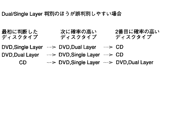
図8は、DL/SL判別よりも、DVD/CD判別の方が誤判別しやすい場合のディスクの種類の判別順序を表している。同図に示すように、最初に判別したのがSLディスクであるとすると、DL/SL判別の方は(反射率に基づくディスクの種類の判別の方は)正しいものと仮定すると、装着されているのは、SLディスクに近い反射率を有するCDである確率が高いということになる。換言すれば、いま装着されているのがDLディスクであるとすると、CD判別センサ4によるトラックピッチからみた判別も、反射率からみた判別も、両方とも誤ったということになるので、両方が誤る確率よりは、一方が誤る確率(一方が正しい確率)の方が高いので、このように判定する。そして、いま装着されているのがCDでもないと判定されたとき、最後に、そのディスクはDLディスクであると判定する。
【0056】
このときの判定の順番は、図7と比較して明らかなように、DL/SL判別の方が誤判別しやすい場合と異なる順番となる。
【0057】
一方、DVD/CD判別の方が誤判別しやすい場合であって、最初にDLディスクと判定された場合には、それが誤っているのであれば、そのディスクは、SLディスクまたはCDということになる。それがCDであるとすると、DVD/CD判別だけでなく、反射率から行ったDL/SLの判別も間違っていたことになる。そこで、一方の判別処理(DVD/CDの判別処理)は正しかったものとして、いま装着されているのは、SLディスクであると判定する。そして、それがSLディスクでもない場合においては、最後にCDであると判定するようにする。
【0058】
最初にCDが装着されていると判定された場合においては、それが誤りであるのであれば、近い反射率を有するSLディスクである確率が高い。そこで、この場合には、いま装着されているのは、CDではなく、SLディスクであると判定し、SLディスクでもない場合には、DLディスクであると判定するようにする。
【0059】
以上のようにして、より高い確率のディスクが推定される。
【0060】
そして、図2のステップS16において、Disc Type Retryに保持されている値が、1だけインクリメントされ、いまの場合、2とされる。ステップS17においては、インクリメントされた値が3より小さいか否かが判定され、いまの場合、3より小さいので、ステップS5に戻り、再びステップS15で推定されたディスクに対応するパラメータを設定する処理が実行される。そして、その状態で、上述した場合と同様にして、フォーカスサーボがオンされ、ロックするかどうかが判定される。
【0061】
以上のようにして、3つの種類のディスクのうち、いずれのディスクに対応するパラメータを設定した場合においても、フォーカスサーボをロックすることができなかった場合においては、ステップS17において、NOの判定が行われ、ステップS18において、いま装着されているディスクが再生不能のディスクであると判定される。
【0062】
一方、ステップS9において、フォーカスサーボがロックしたと判定された場合においては、ステップS19に進み、レジスタCLV Retryに0が初期設定される。このCLV Retryは、CLVサーボをオンする回数を管理するものである。ステップS20においては、CPU15は、CLVコントローラ11を制御し、ラフサーボをオンさせる。これにより、スピンドルモータ2は、周波数サーボ状態とされる。次に、ステップS21において、CPU15は、サーボプロセッサ18を制御し、トラッキングサーボをオンさせる。また、ステップS22において、CPU15は、CLVコントローラ11を制御し、ステップS20で実行したラフサーボに替えて、CLVサーボをオンさせる。
【0063】
さらに、ステップS23に進み、CPU15は、内蔵するリミットタイマを設定し、ステップS24において、CLVサーボがロックしたか否かを判定する。CLVサーボがロックしない場合、ステップS25に進み、ステップS23で設定したリミットタイマがオーバーしたか否かを判定する。リミットタイマがオーバーしていない場合、ステップS24に戻り、再びCLVサーボがロックしたか否かを判定する。
【0064】
以上のようにして、ステップS24,S25の処理を繰り返し、リミットタイマがオーバーするまでの間に、CLVサーボがロックしなかった場合には、ステップS26に進み、CPU15は、再びCLVサーボに替えて、ラフサーボをオンさせる。次に、ステップS27で、CPU15は、トラッキングサーボをオフにした後、ステップS28で、レジスタCLV Retryに保持されている値を1だけインクリメントする。いまの場合、1を記憶させる。ステップS29においては、いまインクリメントされた値が3以上であるか否かが判定される。いまの場合、3未満であるから、NOの判定が行われ、ステップS30に進む。ステップS30においては、CPU15は、ピックアップ5を外周に移動させ、CLVサーボのロック位置を異なる位置に変更させる。そして、ステップS20に戻り、それ以降の処理を再び実行する。
【0065】
以上のようにして、所定の時間内に、CLVサーボをロックすることができなかった状態が3回連続して発生した場合においては、ステップS29からステップS31に進み、レジスタDisc Type Retryの値が3未満であるか否かが判定される。この値が3以上である場合においては、3種類のディスクのいずれに対応するパラメータを設定した場合においても、フォーカスサーボまたはCLVサーボをロックすることができなかったことになる。そこで、この場合においては、ステップS36に進み、いま装着されているディスクは、再生不能のディスクであると判定する。
【0066】
ステップS31において、Disc Type Retryが3未満であると判定された場合においては、ステップS32に進み、確率的に高いディスクの種類を推定する処理が実行される。この処理は、上述したステップS15の処理と同様の処理である。
【0067】
そして、ステップS33に進み、Disc Type Retryに保持されている値を1だけインクリメントし、ステップS34において、フォーカスサーボがオフされる。ステップS35において、CPU15は、ピックアップ5をホームポジションに移動させる(フォーカスサーボをロックする位置に移動させる)。そして、ステップS5に戻り、ステップS32で推定されたディスクに対応するパラメータを設定する処理が行われ、上述した場合と同様にして、フォーカスサーボをロックする処理が実行される。すなわち、フォーカスサーボが、一旦ロックしたとしても、CLVサーボをロックすることができなかった場合においては、ディスクの種類の設定が誤っているものとして、再びフォーカスサーボをロックする動作と、CLVサーボをロックする動作が実行される。
【0068】
ステップS24において、CLVサーボがロックしたと判定された場合、結局、フォーカスサーボとCLVサーボの両方がロックしたことになる。そこで、この場合においては、ステップS37に進み、CPU15は、サーボプロセッサ18を制御し、スレッドサーボをオンさせる。ステップS38においては、アドレスデコーダ12より読み込まれるアドレスを格納する動作を許容し、ステップS39において、ディスク1から読み取ったアドレスの連続性を確認する。そして、ステップS40に進み、ディスク1の再生処理を行う。
【0069】
以上の実施の形態においては、DVDとCDを再生する場合を例として説明したが、その他のディスクに対してデータを記録または再生する場合にも、本発明は適用することが可能である。
【0070】
【発明の効果】
以上の如く、請求項1に記載のディスク判別装置および請求項6に記載のディスク判別方法によれば、ディスクの種類を確率に基づき推定し、その推定結果に対応して、ディスクのサーボを制御するようにしたので、迅速かつ確実にディスクの種類を判別し、ディスクを記録または再生可能な状態とすることができる。
【図面の簡単な説明】
【図1】本発明のディスク記録再生装置の構成を示すブロック図である。
【図2】図1のディスク記録再生装置の起動時の動作を説明するフローチャートである。
【図3】図2に続くフローチャートである。
【図4】図2のステップS3におけるDVDとCDを判別する処理を説明するフローチャートである。
【図5】図2のステップS3におけるDLディスクとSLディスクの判別処理を説明するフローチャートである。
【図6】DLディスクとSLディスクの判別動作を説明する図である。
【図7】ディスクの種類を判別する確率を説明する図である。
【図8】ディスクの種類を判別する確率を説明する他の図である。
【符号の説明】
1 ディスク, 2 スピンドルモータ, 3 チルトセンサ, 4 CD判別センサ, 5 ピックアップ, 11 CLVコントローラ, 12 スピンドルモータドライバ, 15 CPU, 17 ピークホールド回路, 18 サーボプロセッサ, 20 ピックアップドライバ, 19 EEPROM[0001]
BACKGROUND OF THE INVENTION
The present invention provides a disc Discrimination In particular, a disc capable of quickly and accurately discriminating the type of disc. Discrimination The present invention relates to an apparatus and a method.
[0002]
[Prior art]
Recently, a DVD (Digital Varsatile Disc) has been standardized and is becoming popular. This DVD defines a single layer disc (SL disc) having one information recording layer and a dual layer disc (DL disc) in which two information recording layers are formed. Assuming that a CD (Compact Disc) can be played back in a device that records or plays back data on a DVD, a total of three types of discs are loaded. Which of these is loaded? Need to be determined.
[0003]
[Problems to be solved by the invention]
The DVD is provided with a control data area in which data relating to the type of the disk is recorded. The CD also has a TOC area in which data relating to the type of disc is recorded. Therefore, it is theoretically possible to determine the type of the disk by reading these control data area or TOC area.
[0004]
However, in order to read these data, various servos such as a focus servo, a tracking servo, and a spindle servo must be locked, and there has been a problem that the type of the disk cannot be determined before that.
[0005]
For example, parameters such as laser beam power or gain for amplifying a reproduction RF signal need to be set before data is reproduced. If the setting is not correct, the data cannot be read in the worst case.
[0006]
Therefore, it is necessary to accurately discriminate the disc type and set the correct parameters, but if you try to discriminate the disc type as accurately as possible, it takes time to obtain the discriminant result. As a result, there is a problem that it takes a long time until a state where data can be actually recorded or reproduced after the disc is mounted on the apparatus.
[0007]
The present invention has been made in view of such a situation, and makes it possible to quickly and reliably discriminate the type of a disk.
[0008]
[Means for Solving the Problems]
The disc discriminating apparatus according to
[0009]
[0010]
Disc according to
[0011]
DETAILED DESCRIPTION OF THE INVENTION
[0012]
[0013]
[0015]
[0016]
FIG. 1 is a block diagram showing a configuration example of a disk recording / reproducing apparatus of the present invention. The
[0017]
The
[0018]
The
[0019]
The
[0020]
The
[0021]
The preamplifier 6 individually outputs signals output from the photodiodes A to F to the
[0022]
Further, the
[0023]
In the
[0024]
Next, with reference to the flowcharts of FIGS. 2 and 3, the operation at the time of starting the disk recording / reproducing apparatus of FIG. 1 will be described.
[0025]
First, in step S1, the
[0026]
Next, in step S <b> 2, the
[0027]
Details of the DVD / CD discrimination processing are shown in the flowchart of FIG.
[0028]
In this process, first, in step S91, the
[0029]
On the other hand, if it is determined in step S92 that the
[0030]
In this way, when the
[0031]
Details of the DL / SL discrimination processing are shown in the flowchart of FIG.
[0032]
That is, in step S101, the
Here, the meaning of the above formula will be described. That is, between the SL disk and the DL disk, the SL disk has a higher reflectance, and the DL disk has a lower reflectance. Threshold level PI R1 Is a threshold level for discriminating between the SL disk and the DL disk based on the difference in reflectance, and the drive voltage shown in FIG. 6 (B) causes the
[0034]
As described above, the
[0035]
However, these values change in proportion to the set laser power or gain value. Furthermore, the state changes even when the focus servo is not applied and when the focus servo is applied. Now, LP mode parameter LP related to laser power SL , LP DL The ratio of the values is a to b as shown in the following equation.
LP SL : LP DL = A: b
[0036]
Similarly, the parameter G of the SL mode and DL mode related to the gain SL , G DL The ratio of c is d as shown in the following equation.
G SL : G DL = C: d
[0037]
Further, the ratio between the level of the pull-in signal when the focus servo is off and the level PI focus off and PI focus on of the pull-in signal when the focus servo is on is represented by e to f as shown in the following equation.
PIfocusoff: PIfocuson = e: f
[0038]
As a result, the maximum level PI (dldisc, slmode) of the pull-in signal when the DL disc is reproduced in the SL mode is expressed by the following equation.
PI (dldisc, slmode) = (PI (dldisc, dlmode) −PIref) × (a / b) × (c / d) × (e / f) + PIref (2)
[0039]
Further, the maximum level PI (sldisc, slmode) of the pull-in signal of the SL disk is expressed by the following equation.
PI (sldisc, slmode) = (PI (sldisc, slmode) −PIref) × (e / f) + PIref (3)
[0040]
Therefore, the equation (1) can be obtained from the above equations (2) and (3).
[0041]
After the disc determination process is performed as described above, the process proceeds to step S4 in FIG. 2, and the
[0042]
In step S6, the
[0043]
As a result, the outputs of the photodiodes A to D output from the preamplifier 6 are calculated in the
[0044]
In step S9, the
[0045]
If it is determined in step S10 that the limit timer has expired in a state where the focus servo is not locked, the process proceeds to step S11, and the
[0046]
In step S13, it is determined whether or not the value of the register Focus Retry is 3 or more. In this case, since the value is 1, NO is determined, and the process proceeds to step S14. In step S <b> 14, the
[0047]
Next, returning to step S7, the limit timer is set again, and the focus servo is turned on in step S8. In steps S9 and S10, the process waits until the focus servo is locked before the limit timer expires. If the focus servo is not locked, the focus servo is turned off again in step S11, and the value of the register Focus Retry is incremented by one.
[0048]
As described above, when the focus servo is not locked before the limit timer expires, the operation to turn on the focus servo is executed three times. If the focus servo cannot be locked even in the third operation, a determination of YES is made in step S13, and the process proceeds to step S15 to execute a process of estimating the type of the disc that is stochastically high. .
[0049]
That is, as described above, in the case of this embodiment, the process shown in the flowchart of FIG. 4 is executed in accordance with the determination result of the
[0050]
That is, as shown in the figure, if it is determined that the currently mounted DVD is an SL disk as a result of the two determinations, parameters corresponding to this disk are set and 3 Attempts were made to lock the focus servo twice, but eventually the focus servo could not be locked, so this determination is considered to be incorrect. Therefore, the next conceivable thing is that the mounted DL disc or CD. Which of these is determined from the probability of misclassification of two types of discrimination.
[0051]
In this case, the DL / SL discrimination is easier to make an erroneous discrimination than the CD discrimination. In other words, the discrimination result by the
[0052]
If it is determined that the disc that has been mounted is not a DL disc, it is finally determined that a CD is currently mounted.
[0053]
In addition, when the DL disc is currently installed, the probability that the disc is at least DVD is high, so the disc type to be selected next is the SL disc. CD is selected.
[0054]
On the other hand, the DL disc and the CD have greatly different reflectivities, and the SL disc and the CD have close reflectivities. If the DL disc is erroneously determined as a CD, or conversely, if the CD is erroneously determined as a DL disc, both the determination based on the track pitch and the determination based on the reflectance are incorrect. The probability that both such two decisions are wrong is small. Therefore, when it is determined that the disc is a DL disc or a CD, it is assumed that at least the discrimination from the viewpoint of the reflectance is correct and that it is an error of the SL disc. If it is not an SL disk, it is assumed that it is the remaining disk.
[0055]
FIG. 8 shows a discriminating order of disc types when DVD / CD discrimination is easier to discriminate than DL / SL discrimination. As shown in the figure, when it is assumed that the SL disc is first discriminated, it is assumed that the DL / SL discriminating method is correct (the disc type discriminating method based on the reflectance) is installed. This means that there is a high probability that the CD has a reflectance close to that of the SL disk. In other words, if it is the DL disc that is currently loaded, both the discriminating from the track pitch by the
[0056]
As is clear from the comparison with FIG. 7, the order of determination at this time is different from the case where DL / SL determination is more likely to be erroneously determined.
[0057]
On the other hand, in the case where DVD / CD discrimination is more likely to be erroneously discriminated, and it is first discriminated as a DL disc, if it is wrong, the disc is called an SL disc or a CD. Become. If it is a CD, this means that not only DVD / CD discrimination but also DL / SL discrimination based on reflectance is wrong. Therefore, it is determined that one of the discriminating processes (DVD / CD discriminating process) is correct and it is the SL disc that is currently mounted. If it is not an SL disc, it is finally determined that the disc is a CD.
[0058]
In the case where it is first determined that a CD is mounted, if it is an error, there is a high probability that it is an SL disk having a close reflectance. Therefore, in this case, it is determined that it is not a CD but an SL disk that is currently mounted, and if it is not an SL disk, it is determined that it is a DL disk.
[0059]
As described above, a disk having a higher probability is estimated.
[0060]
Then, in step S16 of FIG. 2, the value held in the Disc Type Retry is incremented by 1, and in this case, it is set to 2. In step S17, it is determined whether or not the incremented value is smaller than 3. In this case, since it is smaller than 3, the process returns to step S5, and again sets the parameter corresponding to the disk estimated in step S15. Is executed. In this state, the focus servo is turned on and whether or not to lock is determined in the same manner as described above.
[0061]
As described above, even when the parameters corresponding to any of the three types of disks are set, if the focus servo cannot be locked, NO is determined in step S17. In step S18, it is determined that the currently loaded disc is an unreproducible disc.
[0062]
On the other hand, if it is determined in step S9 that the focus servo is locked, the process proceeds to step S19, and 0 is initially set in the register CLV Retry. This CLV Retry manages the number of times the CLV servo is turned on. In step S20, the
[0063]
In step S23, the
[0064]
As described above, the processes of steps S24 and S25 are repeated, and if the CLV servo is not locked before the limit timer expires, the process proceeds to step S26, and the
[0065]
As described above, when the state where the CLV servo could not be locked has occurred three times within a predetermined time, the process proceeds from step S29 to step S31, and the value of the register Disc Type Retry is set. It is determined whether it is less than 3. When this value is 3 or more, the focus servo or CLV servo could not be locked even when the parameters corresponding to any of the three types of disks were set. Therefore, in this case, the process proceeds to step S36, and it is determined that the currently loaded disc is a disc that cannot be reproduced.
[0066]
If it is determined in step S31 that Disc Type Retry is less than 3, the process proceeds to step S32, and a process of estimating the type of the disc that is stochastically high is executed. This process is the same as the process of step S15 described above.
[0067]
In step S33, the value held in the Disc Type Retry is incremented by 1. In step S34, the focus servo is turned off. In step S35, the
[0068]
If it is determined in step S24 that the CLV servo is locked, it means that both the focus servo and the CLV servo are locked. Therefore, in this case, the process proceeds to step S37, and the
[0069]
In the above embodiment, the case of reproducing DVD and CD has been described as an example. However, the present invention can also be applied to the case of recording or reproducing data on other disks.
[0070]
【The invention's effect】
As described above, the disk according to
[Brief description of the drawings]
FIG. 1 is a block diagram showing a configuration of a disk recording / reproducing apparatus of the present invention.
FIG. 2 is a flowchart for explaining an operation at the time of activation of the disk recording / reproducing apparatus of FIG. 1;
FIG. 3 is a flowchart following FIG. 2;
FIG. 4 is a flowchart for describing processing for discriminating between DVD and CD in step S3 of FIG.
FIG. 5 is a flowchart for explaining a DL disc / SL disc discrimination process in step S3 of FIG. 2;
FIG. 6 is a diagram for explaining a discrimination operation between a DL disk and an SL disk.
FIG. 7 is a diagram illustrating the probability of discriminating the type of disk.
FIG. 8 is another diagram for explaining the probability of discriminating the type of disk.
[Explanation of symbols]
1 disk, 2 spindle motor, 3 tilt sensor, 4 CD discriminating sensor, 5 pickup, 11 CLV controller, 12 spindle motor driver, 15 CPU, 17 peak hold circuit, 18 servo processor, 20 pickup driver, 19 EEPROM
Claims (16)
異なるフォーマットのディスクを判別する第1の判別手段と、
同じフォーマットのディスクであって、情報記録層の数が異なるディスクを判別する第2の判別手段と、
前記第1及び第2の判別手段による最初のディスクの種類の判別結果が誤っていたとき、前記第1及び第2の判別結果、前記再生手段により再生される少なくとも3種類のディスクの物理特徴、並びに前記第1及び第2の判別手段の誤判断のしやすさに基づいて、残りの複数のディスクの種類のうち確率が高いと推定される方の種類のディスクを再生するように前記再生手段を制御する制御手段と
を備えることを特徴とするディスク判別装置。Playback means for playing back at least three types of discs;
First discriminating means for discriminating discs of different formats;
Second discriminating means for discriminating discs having the same format and different information recording layers;
When the discriminating result of the first disc type by the first and second discriminating means is incorrect, the first and second discriminating results , physical characteristics of at least three types of discs reproduced by the reproducing unit; In addition, based on the ease of misjudgment of the first and second discriminating means, the reproducing means is adapted to reproduce the type of disk that is estimated to have a higher probability among the remaining types of discs. And a disc discriminating apparatus comprising: a control means for controlling the disc.
前記設定手段は、前記判別手段より判別された種類のディスクに対応する前記パラメータが設定された状態でサーボを制御することができなかったとき、前記残りの複数のディスクの種類のうち確率が高い順序のディスクの種類に対応する前記パラメータを設定する
ことを特徴とする請求項1に記載のディスク判別装置。Corresponding to the estimation result, further comprising setting means for setting a predetermined parameter,
The setting means has a high probability of the types of the remaining plurality of disks when the servo cannot be controlled with the parameters corresponding to the types of disks determined by the determination means being set. 2. The disk discriminating apparatus according to claim 1, wherein the parameter corresponding to the type of the disc in the order is set.
ことを特徴とする請求項2に記載のディスク判別装置。The said setting means sets the said parameter corresponding to the said estimated kind of said disk, when the said control means cannot control the servo of the said disk several times. Disc discriminator.
ことを特徴とする請求項3に記載のディスク判別装置。In the case where the parameter corresponding to any type of the disk is set, it is further provided with a determination unit that determines that the type of the disk cannot be determined when the servo cannot be controlled a predetermined number of times. The disk discriminating apparatus according to claim 3.
前記第1及び第2の判別手段による最初のディスクの種類の判別結果が誤っていた場合、前記制御手段は、
前記第1及び第2の判別手段により、前記第1のディスクと判別されていたとき、前記第2のディスクを再生するように前記再生手段を制御し、
前記第1及び第2の判別手段により、前記第2のディスクと判別されていたとき、前記第3のディスクを再生するように前記再生手段を制御し、
前記第1及び第2の判別手段により、前記第3のディスクと判断された場合には、前記第2のディスクを再生するように前記再生手段を制御する
ことを特徴とする請求項1に記載のディスク判別装置。 The three types of discs are a first disc with one information recording layer recorded in the first format, a second disc with one information recording layer recorded in the second format, In the case where the information recording layer recorded in the format is a two-layer third disc, and the second discriminating unit is more likely to be misidentified than the first discriminating unit
If the first disc type discriminating result by the first and second discriminating means is incorrect, the control means
When the first and second discriminating means discriminates the first disc, the playback means is controlled to play the second disc;
When the first and second discriminating means discriminates the disc as the second disc, the playback means is controlled to play the third disc;
When the first discriminating means and the second discriminating means determine that the disc is the third disc, the playback means is controlled to play the second disc.
The disk discriminating apparatus according to claim 1, wherein:
ことを特徴とする請求項5のディスク判別装置。6. The disc discriminating apparatus according to claim 5, wherein:
前記第1及び第2の判別手段による最初のディスクの種類の判別結果が誤っていた場合、前記制御手段は、If the first disc type discriminating result by the first and second discriminating means is incorrect, the control means
前記第1及び第2の判別手段により、前記第1のディスクと判別されていたとき、前記第2のディスクを再生するように前記再生手段を制御し、When the first and second discriminating means discriminates the first disc, the playback means is controlled to play the second disc;
前記第1及び第2の判別手段により、前記第2のディスクと判別されていたとき、前記第1のディスクを再生するように前記再生手段を制御し、When the first and second discriminating means discriminates the disc as the second disc, the playback means is controlled to play the first disc;
前記第1及び第2の判別手段により、前記第3のディスクと判別されていたとき、前記第2のディスクを再生するように前記再生手段を制御するWhen the disc is determined to be the third disc by the first discriminating means and the second discriminating means, the reproducing means is controlled to reproduce the second disc.
ことを特徴とする請求項1に記載のディスク判別装置。The disk discriminating apparatus according to claim 1.
ことを特徴とする請求項7のディスク判別装置。8. The disc discriminating apparatus according to claim 7, wherein:
異なるフォーマットのディスクを判別する第1の判別ステップと、
同じフォーマットのディスクであって、情報記録層の数が異なるディスクを判別する第2の判別ステップと、
前記第1及び第2の判別ステップによる最初のディスクの種類の判別結果が誤っていたとき、前記第1及び第2の判別結果、前記再生ステップの処理により再生される少なくとも3種類のディスクの物理特徴、並びに前記第1及び第2の判別手段の誤判断のしやすさに基づいて、残りの複数のディスクの種類のうち確率が高い順序と推定される方の種類のディスクを再生するように前記再生ステップの処理を制御する制御ステップと
を含むことを特徴とするディスク判別方法。 A playback step for playing back at least three types of discs;
A first discriminating step for discriminating discs of different formats;
A second discriminating step for discriminating discs having the same format and different information recording layers;
When the discriminating result of the first disc type in the first and second discriminating steps is wrong , the physical discriminating of at least three discs reproduced by the processing of the first and second discriminating results and the reproducing step. Based on the characteristics and ease of misjudgment of the first and second discriminating means, the disc of the type of the remaining plurality of disc types that is estimated to have the highest probability is reproduced. And a control step for controlling the processing of the reproduction step.
前記設定ステップは、前記判別ステップにより判別された種類の前記ディスクに対応する前記パラメータが設定された状態でサーボを制御することができなかったとき、前記残りの複数のディスクの種類のうち確率が高い順序のディスクの種類に対応する前記パラメータを設定する
ことを特徴とする請求項9に記載のディスク判別方法。A setting step for setting a predetermined parameter in response to the estimation result;
In the setting step, when the servo cannot be controlled in a state where the parameter corresponding to the type of the disc determined in the determination step is set, the probability among the types of the remaining plurality of discs is 10. The disk discriminating method according to claim 9, wherein the parameters corresponding to the types of disks in a high order are set.
ことを特徴とする請求項10に記載のディスク判別方法。Said setting step, when said control step could not be controlled several times a servo of the disc, according to claim 10, characterized by setting the parameter corresponding to the estimated type of the disc disk discriminating method.
ことを特徴とする請求項11に記載のディスク判別方法。In the case where the parameter corresponding to any type of the disk is set, the method further comprises the step of determining that the type of the disk is not determined when the servo cannot be controlled a predetermined number of times. The disc discrimination method according to claim 11 .
前記第1及び第2の判別ステップの処理による最初のディスクの種類の判別結果が誤っていた場合、前記制御ステップにおいては、
前記第1及び第2の判別ステップの処理により、前記第1のディスクと判別されていたとき、前記第2のディスクを再生するように制御され、
前記第1及び第2の判別ステップの処理により、前記第2のディスクと判別されていたとき、前記第3のディスクを再生するように制御され、
前記第1及び第2の判別ステップの処理により、前記第3のディスクと判断された場合には、前記第2のディスクを再生するように制御される
ことを特徴とする請求項9に記載のディスク判別方法。 The three types of discs are a first disc with one information recording layer recorded in the first format, a second disc with one information recording layer recorded in the second format, When the information recording layer recorded in the format is a two-layer third disk, and the determination process in the second determination step is more likely to be erroneously determined than the determination process in the first determination step. ,
When the discriminating result of the first disc type by the processing of the first and second discriminating steps is incorrect, in the control step,
When the disc is determined to be the first disc by the processing of the first and second discriminating steps, it is controlled to play the second disc,
When the disc is determined to be the second disc by the processing of the first and second discriminating steps, it is controlled to reproduce the third disc,
When it is determined that the disc is the third disc by the processing of the first and second discriminating steps, the second disc is controlled to be reproduced.
The disc discrimination method according to claim 9.
ことを特徴とする請求項13のディスク判別方法。14. The disc discrimination method according to claim 13, wherein:
前記第1及び第2の判別ステップの処理による最初のディスクの種類の判別結果が誤っていた場合、前記制御ステップにおいては、When the discriminating result of the first disc type by the processing of the first and second discriminating steps is incorrect, in the control step,
前記第1及び第2の判別ステップの処理により、前記第1のディスクと判別されていたとき、前記第2のディスクを再生するように制御され、When the disc is determined to be the first disc by the processing of the first and second discriminating steps, it is controlled to play the second disc,
前記第1及び第2の判別ステップの処理により、前記第2のディスクと判別されていたとき、前記第1のディスクを再生するように制御され、When the first disc is determined to be the second disc by the processing of the first and second discriminating steps, the first disc is controlled to be reproduced,
前記第1及び第2の判別ステップの処理により、前記第3のディスクと判別されていたとき、前記第3のディスクを再生するように制御されるWhen the disc is determined to be the third disc by the processing of the first and second discriminating steps, the third disc is controlled to be reproduced.
ことを特徴とする請求項9に記載のディスク判別装置。The disk discriminating apparatus according to claim 9.
ことを特徴とする請求項15のディスク判別方法。16. The disc discrimination method according to claim 15, wherein:
Priority Applications (12)
| Application Number | Priority Date | Filing Date | Title |
|---|---|---|---|
| JP28356896A JP3619625B2 (en) | 1996-10-25 | 1996-10-25 | Disk discriminating apparatus and method |
| US08/955,847 US6072757A (en) | 1996-10-25 | 1997-10-21 | Apparatus and method for determining a disk type prior to reproducing data from the disk |
| EP97308382A EP0838818B1 (en) | 1996-10-25 | 1997-10-22 | Determination of disk types and reproducing data from disks |
| DE69738663T DE69738663D1 (en) | 1996-10-25 | 1997-10-22 | Determine the disk type and playback of disk data |
| TW086115631A TW394930B (en) | 1996-10-25 | 1997-10-22 | Apparatus and method for determining a disk type prior to reproducing data from the disk |
| ES97308382T ES2304790T3 (en) | 1996-10-25 | 1997-10-22 | DETERMINATION OF TYPES OF DISCS AND REPRODUCTION OF DISC DATA. |
| IDP973513A ID18825A (en) | 1996-10-25 | 1997-10-23 | AIRCRAFT AND PROCEDURES FOR DETERMINING TYPES OF PLATS BEFORE RECORDING DATA FROM PLATES |
| MYPI97005002A MY120707A (en) | 1996-10-25 | 1997-10-23 | Apparatus and method for determining a disk type prior to reproducing data from the disk |
| MXPA/A/1997/008158A MXPA97008158A (en) | 1996-10-25 | 1997-10-23 | Apparatus and method for determining a type of disc before reproducing the data of the di |
| AU42846/97A AU724784B2 (en) | 1996-10-25 | 1997-10-24 | Apparatus and method for determining a disk type prior to reproducing data from the disk |
| CN97120812A CN1129132C (en) | 1996-10-25 | 1997-10-25 | Device and method for determing CD type before reproducing data in CD |
| KR1019970055880A KR100508192B1 (en) | 1996-10-25 | 1997-10-25 | Apparatus and method for determining disc type before playing data from a disc |
Applications Claiming Priority (1)
| Application Number | Priority Date | Filing Date | Title |
|---|---|---|---|
| JP28356896A JP3619625B2 (en) | 1996-10-25 | 1996-10-25 | Disk discriminating apparatus and method |
Publications (2)
| Publication Number | Publication Date |
|---|---|
| JPH10134497A JPH10134497A (en) | 1998-05-22 |
| JP3619625B2 true JP3619625B2 (en) | 2005-02-09 |
Family
ID=17667218
Family Applications (1)
| Application Number | Title | Priority Date | Filing Date |
|---|---|---|---|
| JP28356896A Expired - Fee Related JP3619625B2 (en) | 1996-10-25 | 1996-10-25 | Disk discriminating apparatus and method |
Country Status (11)
| Country | Link |
|---|---|
| US (1) | US6072757A (en) |
| EP (1) | EP0838818B1 (en) |
| JP (1) | JP3619625B2 (en) |
| KR (1) | KR100508192B1 (en) |
| CN (1) | CN1129132C (en) |
| AU (1) | AU724784B2 (en) |
| DE (1) | DE69738663D1 (en) |
| ES (1) | ES2304790T3 (en) |
| ID (1) | ID18825A (en) |
| MY (1) | MY120707A (en) |
| TW (1) | TW394930B (en) |
Families Citing this family (17)
| Publication number | Priority date | Publication date | Assignee | Title |
|---|---|---|---|---|
| KR100272493B1 (en) * | 1997-08-30 | 2000-11-15 | 윤종용 | Apparatus of processing data for digital video disk and compact disk |
| JPH11120683A (en) * | 1997-10-15 | 1999-04-30 | Mitsumi Electric Co Ltd | Optical disk device |
| DE19755741A1 (en) * | 1997-12-16 | 1999-06-17 | Thomson Brandt Gmbh | CD player for CD-like recording formats |
| US6601046B1 (en) * | 1999-03-25 | 2003-07-29 | Koninklijke Philips Electronics N.V. | Usage dependent ticket to protect copy-protected material |
| JP3586403B2 (en) * | 2000-01-13 | 2004-11-10 | パイオニア株式会社 | Recording medium reproducing method and apparatus |
| JP3979560B2 (en) * | 2000-08-24 | 2007-09-19 | パイオニア株式会社 | Disc type discrimination method and reproducing apparatus thereof |
| KR100722589B1 (en) * | 2000-12-29 | 2007-05-28 | 엘지전자 주식회사 | Method for interfacing a combo drive system with host |
| US6940794B2 (en) * | 2001-08-03 | 2005-09-06 | Matsushita Electric Industrial Co., Ltd. | Information recording/reproducing apparatus that determines the number of recording layers of an information recording medium |
| JP2004342157A (en) * | 2003-05-13 | 2004-12-02 | Pioneer Electronic Corp | Recording medium discriminating device, information reproducing device, and information recording device |
| JP4342930B2 (en) * | 2003-12-25 | 2009-10-14 | 株式会社東芝 | Optical disc apparatus, control method therefor, and recording medium |
| KR100532612B1 (en) | 2004-06-18 | 2005-12-01 | 삼성전자주식회사 | Method and device for changing the play mode |
| JP2006114100A (en) * | 2004-10-13 | 2006-04-27 | Teac Corp | Optical disk device and starting method of optical disk |
| US20080219111A1 (en) * | 2005-09-09 | 2008-09-11 | Koninklijke Philips Electronics, N.V. | Drive and Method of Operating the Drive and an Optical Data Carrier Therefore |
| CN101000785B (en) * | 2006-01-13 | 2010-05-12 | 鸿富锦精密工业(深圳)有限公司 | Disc kind recognition method and system |
| JP4902589B2 (en) * | 2008-04-18 | 2012-03-21 | 株式会社日立製作所 | Optical disc apparatus and disc discrimination method |
| JP2010118113A (en) * | 2008-11-13 | 2010-05-27 | Sony Corp | Disk driving device and disk discrimination method |
| US8711664B2 (en) * | 2010-06-21 | 2014-04-29 | Mediatek Inc. | Method of controlling mechanical mechanisms of optical storage apparatus for peak power/current reduction, and related optical storage apparatus and machine-readable medium |
Family Cites Families (7)
| Publication number | Priority date | Publication date | Assignee | Title |
|---|---|---|---|---|
| JPS5977606A (en) * | 1982-10-25 | 1984-05-04 | Sony Corp | Reproducing device of digital disc |
| JPS60264173A (en) * | 1984-06-13 | 1985-12-27 | Hitachi Ltd | System for identifying different kind of disc in video disc player |
| US5289451A (en) * | 1984-11-29 | 1994-02-22 | Canon Kabushiki Kaisha | Optical information recording/reproduction apparatus including means for detecting the type of recording medium |
| US5153879A (en) * | 1989-03-23 | 1992-10-06 | Mitsubishi Denki Kabushiki Kaisha | Optical recording system |
| JP3339210B2 (en) * | 1994-07-04 | 2002-10-28 | ソニー株式会社 | Playback device |
| JP3901748B2 (en) * | 1995-01-30 | 2007-04-04 | ソニー株式会社 | Disc-shaped recording medium, recording apparatus and reproducing apparatus therefor |
| JPH08221890A (en) * | 1995-02-17 | 1996-08-30 | Hitachi Ltd | Optical reproducing device |
-
1996
- 1996-10-25 JP JP28356896A patent/JP3619625B2/en not_active Expired - Fee Related
-
1997
- 1997-10-21 US US08/955,847 patent/US6072757A/en not_active Expired - Lifetime
- 1997-10-22 DE DE69738663T patent/DE69738663D1/en not_active Expired - Lifetime
- 1997-10-22 TW TW086115631A patent/TW394930B/en not_active IP Right Cessation
- 1997-10-22 ES ES97308382T patent/ES2304790T3/en not_active Expired - Lifetime
- 1997-10-22 EP EP97308382A patent/EP0838818B1/en not_active Expired - Lifetime
- 1997-10-23 MY MYPI97005002A patent/MY120707A/en unknown
- 1997-10-23 ID IDP973513A patent/ID18825A/en unknown
- 1997-10-24 AU AU42846/97A patent/AU724784B2/en not_active Ceased
- 1997-10-25 CN CN97120812A patent/CN1129132C/en not_active Expired - Fee Related
- 1997-10-25 KR KR1019970055880A patent/KR100508192B1/en not_active IP Right Cessation
Also Published As
| Publication number | Publication date |
|---|---|
| JPH10134497A (en) | 1998-05-22 |
| MY120707A (en) | 2005-11-30 |
| ES2304790T3 (en) | 2008-10-16 |
| CN1198571A (en) | 1998-11-11 |
| MX9708158A (en) | 1998-06-30 |
| CN1129132C (en) | 2003-11-26 |
| KR100508192B1 (en) | 2005-11-08 |
| DE69738663D1 (en) | 2008-06-19 |
| EP0838818A3 (en) | 1999-01-20 |
| TW394930B (en) | 2000-06-21 |
| ID18825A (en) | 1998-05-14 |
| EP0838818B1 (en) | 2008-05-07 |
| KR19980033269A (en) | 1998-07-25 |
| US6072757A (en) | 2000-06-06 |
| AU4284697A (en) | 1998-04-30 |
| EP0838818A2 (en) | 1998-04-29 |
| AU724784B2 (en) | 2000-09-28 |
Similar Documents
| Publication | Publication Date | Title |
|---|---|---|
| JP3619625B2 (en) | Disk discriminating apparatus and method | |
| JP4067781B2 (en) | Disc player | |
| US7230894B2 (en) | Disk having unique code for identifying its type for optical disk player and method for discriminating types thereof | |
| EP1191529B1 (en) | Optical disk drive, and method for identifying optical disks mounted thereto | |
| JP3753267B2 (en) | Disc recording / reproducing apparatus and method | |
| JP3981559B2 (en) | Optical disc apparatus and disc discrimination method thereof | |
| US7948838B2 (en) | Disc discrimination method and apparatus | |
| US7369474B2 (en) | Method of and apparatus for differentiating between writable disc types | |
| JP4060771B2 (en) | Optical disc apparatus and control method thereof | |
| JP4342930B2 (en) | Optical disc apparatus, control method therefor, and recording medium | |
| JP2901769B2 (en) | Optical information recording / reproducing device | |
| US5974014A (en) | Disc reproducing apparatus and method | |
| EP1056083B1 (en) | Optical disc drive and method of controlling optical disc drive | |
| JP2002050040A (en) | Optical disk device | |
| JP3883088B2 (en) | Disc player | |
| JP4370658B2 (en) | Recording method and apparatus | |
| JP4386027B2 (en) | Optical disk playback device | |
| JP4240104B2 (en) | Optical disk device | |
| JP4482539B2 (en) | Optical disc playback apparatus and optical disc playback method | |
| JP2000182314A (en) | Reproducer for optical information recording medium | |
| MXPA97008158A (en) | Apparatus and method for determining a type of disc before reproducing the data of the di | |
| JP2002329333A (en) | Optical disk device and optical disk discriminating method | |
| KR20080072336A (en) | Method for executing auto adjustment in a dvd system | |
| JPH1055606A (en) | Detection of centroid deviated disk of disk player |
Legal Events
| Date | Code | Title | Description |
|---|---|---|---|
| A02 | Decision of refusal |
Free format text: JAPANESE INTERMEDIATE CODE: A02 Effective date: 20020828 |
|
| A521 | Request for written amendment filed |
Free format text: JAPANESE INTERMEDIATE CODE: A523 Effective date: 20040929 |
|
| A61 | First payment of annual fees (during grant procedure) |
Free format text: JAPANESE INTERMEDIATE CODE: A61 Effective date: 20041115 |
|
| FPAY | Renewal fee payment (event date is renewal date of database) |
Free format text: PAYMENT UNTIL: 20071119 Year of fee payment: 3 |
|
| FPAY | Renewal fee payment (event date is renewal date of database) |
Free format text: PAYMENT UNTIL: 20081119 Year of fee payment: 4 |
|
| FPAY | Renewal fee payment (event date is renewal date of database) |
Free format text: PAYMENT UNTIL: 20091119 Year of fee payment: 5 |
|
| FPAY | Renewal fee payment (event date is renewal date of database) |
Free format text: PAYMENT UNTIL: 20091119 Year of fee payment: 5 |
|
| FPAY | Renewal fee payment (event date is renewal date of database) |
Free format text: PAYMENT UNTIL: 20101119 Year of fee payment: 6 |
|
| FPAY | Renewal fee payment (event date is renewal date of database) |
Free format text: PAYMENT UNTIL: 20111119 Year of fee payment: 7 |
|
| FPAY | Renewal fee payment (event date is renewal date of database) |
Free format text: PAYMENT UNTIL: 20121119 Year of fee payment: 8 |
|
| FPAY | Renewal fee payment (event date is renewal date of database) |
Free format text: PAYMENT UNTIL: 20121119 Year of fee payment: 8 |
|
| FPAY | Renewal fee payment (event date is renewal date of database) |
Free format text: PAYMENT UNTIL: 20131119 Year of fee payment: 9 |
|
| R250 | Receipt of annual fees |
Free format text: JAPANESE INTERMEDIATE CODE: R250 |
|
| LAPS | Cancellation because of no payment of annual fees |