EP0802754B1 - Vorrichtung zum erhitzen einer trinkbaren flüssigkeit - Google Patents
Vorrichtung zum erhitzen einer trinkbaren flüssigkeit Download PDFInfo
- Publication number
- EP0802754B1 EP0802754B1 EP95943235A EP95943235A EP0802754B1 EP 0802754 B1 EP0802754 B1 EP 0802754B1 EP 95943235 A EP95943235 A EP 95943235A EP 95943235 A EP95943235 A EP 95943235A EP 0802754 B1 EP0802754 B1 EP 0802754B1
- Authority
- EP
- European Patent Office
- Prior art keywords
- liquid
- valve
- base
- container
- storage container
- Prior art date
- Legal status (The legal status is an assumption and is not a legal conclusion. Google has not performed a legal analysis and makes no representation as to the accuracy of the status listed.)
- Expired - Lifetime
Links
Images


Classifications
-
- A—HUMAN NECESSITIES
- A47—FURNITURE; DOMESTIC ARTICLES OR APPLIANCES; COFFEE MILLS; SPICE MILLS; SUCTION CLEANERS IN GENERAL
- A47J—KITCHEN EQUIPMENT; COFFEE MILLS; SPICE MILLS; APPARATUS FOR MAKING BEVERAGES
- A47J31/00—Apparatus for making beverages
- A47J31/10—Coffee-making apparatus, in which the brewing vessel, i.e. water heating container, is placed above or in the upper part of the beverage containers i.e. brewing vessel; Drip coffee-makers with the water heating container in a higher position than the brewing vessel
- A47J31/106—Coffee-making apparatus, in which the brewing vessel, i.e. water heating container, is placed above or in the upper part of the beverage containers i.e. brewing vessel; Drip coffee-makers with the water heating container in a higher position than the brewing vessel with a valve at the water heating container outlet
-
- A—HUMAN NECESSITIES
- A47—FURNITURE; DOMESTIC ARTICLES OR APPLIANCES; COFFEE MILLS; SPICE MILLS; SUCTION CLEANERS IN GENERAL
- A47J—KITCHEN EQUIPMENT; COFFEE MILLS; SPICE MILLS; APPARATUS FOR MAKING BEVERAGES
- A47J31/00—Apparatus for making beverages
- A47J31/005—Portable or compact beverage making apparatus, e.g. for travelling, for use in automotive vehicles
Definitions
- the invention relates to a device for heating a drinkable liquid with a liquid storage container and an electrical heating element disposed therein, wherein the liquid reservoir has a valve that is below is arranged in the bottom of the liquid storage container, one sealing surface of which is the edge of an opening in the base and that due to a given internal pressure in the container Bulging out of the soil cannot be reversed automatically opens, and the power supply to the heating element so is designed to be interrupted when the pressure in the Liquid storage containers substantially equal to atmospheric pressure is what device on a collection container for the liquid can be put on.
- a known device of this type (EP-A-0479111) is used to do so, on the go, primarily in vehicles Drinks or e.g. also to brew soups.
- a hot drink or soup with you? to take so you put the device on the collection container on and connects the device with an electrical Power source.
- the liquid is then heated and expands thereby, the internal pressure due to the expansion of the Liquid possibly gases in the storage container or increased by gases contained in the liquid becomes. If a certain overpressure is reached, this opens Valve irreversible, and the hot liquid flows into the Collection container.
- a drink or soup is brewed, that in the form of dry matter previously in the Collection container introduced or e.g. in a suitable liquid-permeable container at the bottom of the liquid container is appropriate. Then the device removed and you can remove the liquid from the collection container drink or spoon in the case of soup. It is there also known that the device is reusable and from Users are refilled with liquid and ready for use can be set.
- the device is simple, practical and also safe. In the moment when the liquid is in the collection container has emptied and therefore in the liquid reservoir there can be no overpressure, the power supply interrupted so that the heating element no longer heats up becomes.
- the known device has the disadvantage that on the one hand the flow area of the valve is relatively small. In addition, there is friction of the lip seal when the valve is opened against the annular rim of the bottom opening on what may prevent the valve from opening safely.
- the object of the invention is to create a device of the type mentioned with a valve that works safely and has a large flow area.
- the large flow cross-section has many Cases the advantage that the drinks are brewed more evenly will.
- the solution according to the invention is that the other Sealing surface of the valve a plate-shaped element on the elastic Material that is in its unloaded condition in the essentially conical with the inside of the liquid storage container directed cone tip is shaped and on this tip is held.
- the other sealing surface is but a plate-shaped element made of elastic material that is shaped in its unloaded state so that it is in the essentially occupies the surface of a cone. Will the Bottom pressed inwards, so the edge of the bottom opening comes to lie against this cone and push the edge of the plate-shaped Element inside, so that it seals here Bias is applied to the edge of the opening.
- Bias Bias is applied to the edge of the opening.
- the plug can be in a corresponding Socket with vertical bores, too, so that the device is in the correct orientation for that Heating the liquid is kept.
- the device is then inserted vertically into the socket moves down and can simultaneously in one also vertically placed collection container used will.
- the collecting container can be a sieve filter with a central one Have opening.
- the liquid can flow through the central opening during the brewing process into the collection container come.
- Through the sieve which is arranged in the edge area, then solid residues such as tea leaves or ground coffee retained when drinking the liquid. Besides, will through this screen filter in moving vehicles Spillage of the liquid prevented.
- a container for is advantageously Picking up a device and a collection container the above mentioned type provided that an outlet for inserting the Plug and a recess for inserting the collection container having.
- This container which is particularly case-like can be trained, can easily be taken on trips will. You always have the option of using the Device to prepare heated drinks. It is just a power source is required, for which in motor vehicles 12 volt power supply or 24 volt power supply via the cigarette lighter socket can be used.
- the inventive Device 1 on a plug 2 with which it is plugged into an electrical outlet 3 of a portable container 4 can be used.
- the portable container 4 is with a trough 5 for receiving a Provided collection container 6, in which the invention Device can be used when it moves down is, the plug 2 also being inserted into the socket 3 becomes.
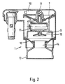
- the device 1 has an upper membrane 7 on, which is acted upon by a spring 8 with pressure is.
- the membrane 7 with the switching cone attached by excess pressure of the liquid reservoir 9 to the outside (upwards in FIG. 2), a microswitch 10 switched by the slope of the switching cone at the stroke, so that a heating cartridge 11 in the liquid reservoir 9 with electricity can be supplied.
- the bottom 12 of the liquid reservoir 9 is also membrane-like, the Membrane has two stable positions, namely once in Fig. 2 shown outward position and the e.g. in Fig. 5 shown inward position.
- a funnel 13 is attached on the membrane 12, a funnel 13 is attached.
- the membrane-shaped bottom 12 has a central opening 14. This opening 14 opposite stands an elastic plate-shaped element 15 which in undeformed state is shaped like a cone shell.
- the operation of the device is as follows.
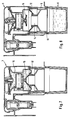
- the device 1 shown in FIG. 2 is turned over, so that it is upside down.
- Fig. 3rd shown position with liquid 16 with the help the funnel 13 filled.
- the Funnel 13 pressed down, causing the bottom membrane 12, such as this is shown in Fig. 4, from the bulging outwards Position in the inwardly curved position shown in Fig. 5 folded down.
- the plate-shaped element 15 deformed inwards and now seals the floor.
- the Device 1 is then turned over, still in funnel 13 Excess liquid 16 is poured away. If it is not water, but e.g. around Milk, so of course less when filling Liquid should be poured in so that no liquid must be thrown away.
- the device 1 is then inserted into the collecting container 6, as shown in Fig. 6, the connector 2nd is inserted into the socket 3 of a container 4, the has a trough 5 for receiving the collecting container 6. Of the Funnel 13 is partially in the collection container 6 introduced.
- the heating element 11 is heated, whereby the liquid 16 heats up.
- the floor membrane 12 is gradually pushed down, the plate-shaped elastic element 15 initially follows and the liquid reservoir 9 still holds closed.
- the Bottom membrane 12 or the annular opening 14 from the plate-shaped elastic element 15 solved that in its original Position returns. Due to the large opening cross-section the liquid can then go down into the collecting container 6 emanate very quickly and suddenly. It is then in Collection container 6 or previously housed in the hopper 13 Brewed material brewed.
- the collecting container 6 can also be removed from the trough 5 can be removed and the drink or soup can be enjoyed will.
- the plate-shaped elastic element also acts as a part a safety valve. If the funnel guide is defective or manipulation by the user, the elastic plate-shaped element 15 required to open the valve Do not carry out the stroke. In this case the internal pressure rise in the water tank and before the tank damage takes, the elastic plate-shaped element 15 slides Valve by deformation of the seat and is in the sleeve 14th pressed. The resulting leak and the reduction in pressure switch off the device.
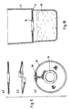
- the collecting container has 6 a stage 17 on which a sieve filter 18 is placed 9 shown in FIG.
- This screen filter 18 has a central opening 19 through which at Brewing the liquid can easily enter.
- the Sieve 20 provided in the edge area can on the one hand at Drinking solid ingredients are withheld. On the other hand can spill the drink in the moving vehicle be prevented.
Description
- Fig. 1
- eine Gesamtansicht des Prinzips der Vorrichtung, des Sammelbehälters und einer Halterung, teilweise im Schnitt;
- Fig. 2
- die Vorrichtung der Erfindung im Schnitt;
- Fig. 3 bis 8
- unterschiedliche Schritte bei der Benutzung der Vorrichtung der Erfindung;
- Fig. 9
- einen Siebfilter, der in den Sammelbehälter eingesetzt werden kann, in verschiedenen Darstellungen; und
- Fig. 10
- im Schnitt den Sammelbehälter mit dem Siebfilter der Fig. 9.
Claims (5)
- Vorrichtung zum Erhitzen einer trinkbaren Flüssigkeit (16) mit einem Flüssigkeitsvorratsbehälter (9) und einem darin angeordneten elektrischen Heizelement (11), wobei der Flüssigkeitsvorratsbehälter (9) ein Ventil (12,15) aufweist, das unten im Boden des Flüssigkeitsvorratsbehälters (9) angeordnet ist, dessen eine Dichtfläche der Rand einer Öffnung (14) des Bodens ist und das sich bei vorgegebenem Behälterinnendruck aufgrund Auswölbens des Bodens nach außen nicht selbsttätig umkehrbar öffnet, und wobei die Stromzuführung zum Heizelement (11) so ausgebildet ist, daß sie unterbrochen wird, wenn der Druck im Flüssigkeitsvorratsbehälter (9) im wesentlichen gleich dem Atmosphärendruck ist, welche Vorrichtung auf einen Sammelbehälter (6) für die Flüssigkeit (16) aufsetzbar ist, dadurch gekennzeichnet, daß die andere Dichtfläche des Ventils ein tellerförmiges Element (15) aus elastischem Material ist, das in seinem unbelasteten Zustand im wesentlichen kegelförmig mit zum Inneren des Flüssigkeitsvorratsbehälters (9) gerichteter Kegelspitze geformt ist und an dieser Spitze gehalten wird.
- Vorrichtung nach Anspruch 1, dadurch gekennzeichnet, daß der Boden (12) mit einem sich nach außen erweiternden Trichter (13) versehen ist.
- Vorrichtung nach Anspruch 1 oder 2, dadurch gekennzeichnet, daß sie einen Stecker (2) für die Zuleitung elektrischen Stroms aufweist, der einen oder mehrere Stifte enthält, die parallel zur in Gebrauchsstellung vertikalen Achse der Vorrichtung (1) ist.
- Vorrichtung nach einem der Ansprüche 1 bis 3 mit einem Sammelbehälter (6), dadurch gekennzeichnet, daß der Sammelbehälter (6) ein Siebfilter (18) mit einer mittigen Öffnung (19) aufweist.
- Behältnis zum Aufnehmen einer Vorrichtung nach einem der Ansprüche 1 bis 4 und eines Sammelbehälters, dadurch gekennzeichnet, daß es eine Steckdose (3) zum Einführen des Steckers (2) sowie eine Ausnehmung (5) zum Einsetzen des Sammelbehälters (6) aufweist.
Applications Claiming Priority (3)
| Application Number | Priority Date | Filing Date | Title |
|---|---|---|---|
| DE29501228U DE29501228U1 (de) | 1995-01-26 | 1995-01-26 | Vorrichtung zum Erhitzen einer trinkbaren Flüssigkeit |
| DE29501228U | 1995-01-26 | ||
| PCT/EP1995/005171 WO1996022719A1 (de) | 1995-01-26 | 1995-12-29 | Vorrichtung zum erhitzen einer trinkbaren flüssigkeit |
Publications (2)
| Publication Number | Publication Date |
|---|---|
| EP0802754A1 EP0802754A1 (de) | 1997-10-29 |
| EP0802754B1 true EP0802754B1 (de) | 1998-07-29 |
Family
ID=8003005
Family Applications (1)
| Application Number | Title | Priority Date | Filing Date |
|---|---|---|---|
| EP95943235A Expired - Lifetime EP0802754B1 (de) | 1995-01-26 | 1995-12-29 | Vorrichtung zum erhitzen einer trinkbaren flüssigkeit |
Country Status (11)
| Country | Link |
|---|---|
| US (1) | US6069996A (de) |
| EP (1) | EP0802754B1 (de) |
| AT (1) | ATE168865T1 (de) |
| AU (1) | AU698757B2 (de) |
| CA (1) | CA2207063A1 (de) |
| DE (2) | DE29501228U1 (de) |
| DK (1) | DK0802754T3 (de) |
| ES (1) | ES2121444T3 (de) |
| PL (1) | PL321513A1 (de) |
| RU (1) | RU2128461C1 (de) |
| WO (1) | WO1996022719A1 (de) |
Families Citing this family (13)
| Publication number | Priority date | Publication date | Assignee | Title |
|---|---|---|---|---|
| DE29801337U1 (de) * | 1998-01-28 | 1999-05-27 | Muench Gmbh | Vorrichtung zum Erhitzen von Trinkwasser |
| DE29802766U1 (de) * | 1998-02-18 | 1999-07-22 | Muench Gmbh | Vorrichtung zum Erhitzen von Trinkwasser |
| DE29803695U1 (de) * | 1998-03-04 | 1999-07-15 | Muench Gmbh | Vorrichtung zum Erhitzen von Trinkwasser |
| EP0974298A1 (de) | 1998-07-20 | 2000-01-26 | Eberhard Timm | Vorrichtung zum Erhitzen einer trinkbaren Flüssigkeit |
| KR100370373B1 (ko) * | 2000-02-29 | 2003-01-29 | 주식회사 피앤티기술 | 휴대용 순간 온수기 |
| EP1468635B1 (de) | 2003-04-17 | 2005-06-22 | Eberhard Timm | Vorrichtung zum Zubereiten heisser Getränke |
| ITFI20060263A1 (it) | 2006-10-27 | 2008-04-28 | Saeco Ipr Ltd | Dispositivo emulsionatore per la produzione di latte schiumato e simili e relativo metodo |
| JP5313230B2 (ja) * | 2007-04-16 | 2013-10-09 | コーニンクレッカ フィリップス エヌ ヴェ | 飲料を生成するための装置及びその装置の使用 |
| RU2462976C2 (ru) * | 2008-04-30 | 2012-10-10 | Ла Марцокко С.Р.Л. | Кофемашина для приготовления кофе эспрессо с устройством предварительного настаивания |
| CN104138213B (zh) * | 2014-06-23 | 2017-06-13 | 陈冬海 | 加热液体用的玻璃器具及其制造方法 |
| CN205649378U (zh) * | 2016-04-11 | 2016-10-19 | 深圳市欧新力奇商贸有限公司 | 咖啡机冲泡装置 |
| CN106490987A (zh) * | 2016-12-30 | 2017-03-15 | 宁波威斯克电器科技有限公司 | 一种即热式可调温和流速的热饮料机 |
| KR102071046B1 (ko) * | 2018-02-05 | 2020-01-28 | 주식회사 이노디자인 | 드립핑 용기 및 휴대용 커피 음용 용기 |
Family Cites Families (8)
| Publication number | Priority date | Publication date | Assignee | Title |
|---|---|---|---|---|
| US2856843A (en) * | 1957-08-02 | 1958-10-21 | Gen Electric | Liquid heating and metering construction |
| DE2121322A1 (de) * | 1971-04-30 | 1972-11-09 | Pönninghaus, Günter, 4971 Lohe | Vorrichtung zum Herstellen von Kaffee, Tee oder sonstigen Aufgußgetränken, zur Benutzung in einem Fahrzeug, in der Form, daß dieses Getränk auch während der Fahrt hergestellt werden kann |
| DE2643557A1 (de) * | 1976-09-28 | 1978-03-30 | Licentia Gmbh | Elektrische filterkaffeemaschine |
| DE3034220A1 (de) * | 1980-09-11 | 1982-04-22 | Basf Ag, 6700 Ludwigshafen | Verfahren und vorrichtung zur kontinuierlichen waschbehandlung von textilmaterialien |
| DE3814359C2 (de) * | 1988-04-28 | 1994-04-28 | Cornelius Dipl Ing Lungu | Magnetventil mit permanentmagnetischer Schließkraft |
| DE8900220U1 (de) * | 1989-01-11 | 1989-03-09 | Metz, Philip | |
| US5259295A (en) * | 1990-10-04 | 1993-11-09 | Eberhard Timm | Container for the preparation of hot drinks |
| DE9013838U1 (de) * | 1990-10-04 | 1992-02-06 | Timm, Eberhard, 2114 Appel, De |
-
1995
- 1995-01-26 DE DE29501228U patent/DE29501228U1/de not_active Expired - Lifetime
- 1995-12-29 WO PCT/EP1995/005171 patent/WO1996022719A1/de active IP Right Grant
- 1995-12-29 US US08/860,398 patent/US6069996A/en not_active Expired - Fee Related
- 1995-12-29 PL PL95321513A patent/PL321513A1/xx unknown
- 1995-12-29 EP EP95943235A patent/EP0802754B1/de not_active Expired - Lifetime
- 1995-12-29 DE DE59503027T patent/DE59503027D1/de not_active Expired - Fee Related
- 1995-12-29 DK DK95943235T patent/DK0802754T3/da active
- 1995-12-29 ES ES95943235T patent/ES2121444T3/es not_active Expired - Lifetime
- 1995-12-29 RU RU97114196A patent/RU2128461C1/ru active
- 1995-12-29 CA CA002207063A patent/CA2207063A1/en not_active Abandoned
- 1995-12-29 AT AT95943235T patent/ATE168865T1/de not_active IP Right Cessation
- 1995-12-29 AU AU44360/96A patent/AU698757B2/en not_active Ceased
Also Published As
| Publication number | Publication date |
|---|---|
| ATE168865T1 (de) | 1998-08-15 |
| ES2121444T3 (es) | 1998-11-16 |
| DK0802754T3 (da) | 1999-05-03 |
| EP0802754A1 (de) | 1997-10-29 |
| AU698757B2 (en) | 1998-11-05 |
| WO1996022719A1 (de) | 1996-08-01 |
| DE29501228U1 (de) | 1995-05-04 |
| US6069996A (en) | 2000-05-30 |
| AU4436096A (en) | 1996-08-14 |
| CA2207063A1 (en) | 1996-08-01 |
| RU2128461C1 (ru) | 1999-04-10 |
| PL321513A1 (en) | 1997-12-08 |
| DE59503027D1 (de) | 1998-09-03 |
Similar Documents
| Publication | Publication Date | Title |
|---|---|---|
| DE602004007883T2 (de) | Integrierte Kapsel zum Extrahieren eines Getränkes | |
| EP0802754B1 (de) | Vorrichtung zum erhitzen einer trinkbaren flüssigkeit | |
| DE602004007881T3 (de) | Integrierte Kapsel zur Zubereitung eines Getränkes aus einer Pulversubstanz | |
| DE602004007479T2 (de) | Integrierte Kapsel zum Extrahieren eines Getränkes | |
| DE602004007478T2 (de) | Anordnung zur Zubereitung eines Getränkes aus einer in einer Kartusche enthaltenen Pulversubstanz | |
| EP2572610B1 (de) | Vorrichtung zur Zubereitung eines Getränkes und Kapsel dazu | |
| EP2566784B1 (de) | Kapsel für ein extraktionsgut und getränke-zubereitungssystem | |
| DE60119754T2 (de) | Kaffeemaschine | |
| EP1710172B1 (de) | Vorrichtung und Wegwerfkapsel zur Erzeugung von flüssigen Produkten, insbesondere Getränken | |
| DE3138779C2 (de) | ||
| EP0699594A1 (de) | Zweikammerbehälter | |
| AT12556U1 (de) | Bausatz zur verbesserung der dichtungseigenschaften einer füllbaren kapsel | |
| DE602004007880T2 (de) | Integrierte Kapsel zur Zubereitung eines Getränkes aus einer Pulversubstanz | |
| EP2418987A2 (de) | Brühmodul | |
| EP1468635B1 (de) | Vorrichtung zum Zubereiten heisser Getränke | |
| EP0382001B1 (de) | Vorrichtung zum Zubereiten heisser Getränke | |
| DE202012104456U1 (de) | Zubereitungsvorrichtung für ein Getränk, insbesondere für Eistee | |
| DE2919523A1 (de) | Aufbrueheinrichtung insbesondere fuer kaffee | |
| DE102006002511A1 (de) | Verfahren zur Zubereitung eines Getränks, Zubereitungseinrichtung für Getränke und Substratbehälter für ein Getränkesubstrat | |
| EP1118298B1 (de) | Vorrichtung zum Zubereiten heisser Getränke | |
| DE1947146C3 (de) | Verschlossener Beutel | |
| DE20217411U1 (de) | Portionspackung und Vorrichtung zur Herstellung eines Aromagetränkes | |
| EP1140655A1 (de) | Brühbeutel für eine filterkaffeebrühvorrichtung | |
| EP2956385A1 (de) | Portionskapsel | |
| DE19839421A1 (de) | Automatisiertes zeitgesteuertes Sieb |
Legal Events
| Date | Code | Title | Description |
|---|---|---|---|
| PUAI | Public reference made under article 153(3) epc to a published international application that has entered the european phase |
Free format text: ORIGINAL CODE: 0009012 |
|
| GRAG | Despatch of communication of intention to grant |
Free format text: ORIGINAL CODE: EPIDOS AGRA |
|
| 17P | Request for examination filed |
Effective date: 19961115 |
|
| AK | Designated contracting states |
Kind code of ref document: A1 Designated state(s): AT BE CH DE DK ES FR GB IT LU NL SE |
|
| 17Q | First examination report despatched |
Effective date: 19971027 |
|
| GRAG | Despatch of communication of intention to grant |
Free format text: ORIGINAL CODE: EPIDOS AGRA |
|
| GRAH | Despatch of communication of intention to grant a patent |
Free format text: ORIGINAL CODE: EPIDOS IGRA |
|
| GRAH | Despatch of communication of intention to grant a patent |
Free format text: ORIGINAL CODE: EPIDOS IGRA |
|
| GRAA | (expected) grant |
Free format text: ORIGINAL CODE: 0009210 |
|
| AK | Designated contracting states |
Kind code of ref document: B1 Designated state(s): AT BE CH DE DK ES FR GB IT LU NL SE |
|
| REF | Corresponds to: |
Ref document number: 168865 Country of ref document: AT Date of ref document: 19980815 Kind code of ref document: T |
|
| REG | Reference to a national code |
Ref country code: CH Ref legal event code: EP |
|
| REF | Corresponds to: |
Ref document number: 59503027 Country of ref document: DE Date of ref document: 19980903 |
|
| REG | Reference to a national code |
Ref country code: CH Ref legal event code: NV Representative=s name: DR. REINHOLD C. SALGO PATENTANWALT |
|
| GBT | Gb: translation of ep patent filed (gb section 77(6)(a)/1977) |
Effective date: 19981006 |
|
| REG | Reference to a national code |
Ref country code: ES Ref legal event code: FG2A Ref document number: 2121444 Country of ref document: ES Kind code of ref document: T3 |
|
| PGFP | Annual fee paid to national office [announced via postgrant information from national office to epo] |
Ref country code: FR Payment date: 19981216 Year of fee payment: 4 |
|
| ET | Fr: translation filed | ||
| PGFP | Annual fee paid to national office [announced via postgrant information from national office to epo] |
Ref country code: ES Payment date: 19981221 Year of fee payment: 4 |
|
| PGFP | Annual fee paid to national office [announced via postgrant information from national office to epo] |
Ref country code: SE Payment date: 19981222 Year of fee payment: 4 Ref country code: BE Payment date: 19981222 Year of fee payment: 4 Ref country code: AT Payment date: 19981222 Year of fee payment: 4 |
|
| PGFP | Annual fee paid to national office [announced via postgrant information from national office to epo] |
Ref country code: LU Payment date: 19981223 Year of fee payment: 4 Ref country code: DK Payment date: 19981223 Year of fee payment: 4 |
|
| REG | Reference to a national code |
Ref country code: DK Ref legal event code: T3 |
|
| PLBE | No opposition filed within time limit |
Free format text: ORIGINAL CODE: 0009261 |
|
| STAA | Information on the status of an ep patent application or granted ep patent |
Free format text: STATUS: NO OPPOSITION FILED WITHIN TIME LIMIT |
|
| 26N | No opposition filed | ||
| PG25 | Lapsed in a contracting state [announced via postgrant information from national office to epo] |
Ref country code: LU Free format text: LAPSE BECAUSE OF NON-PAYMENT OF DUE FEES Effective date: 19991229 Ref country code: GB Free format text: LAPSE BECAUSE OF NON-PAYMENT OF DUE FEES Effective date: 19991229 Ref country code: DK Free format text: LAPSE BECAUSE OF NON-PAYMENT OF DUE FEES Effective date: 19991229 Ref country code: AT Free format text: LAPSE BECAUSE OF NON-PAYMENT OF DUE FEES Effective date: 19991229 |
|
| PG25 | Lapsed in a contracting state [announced via postgrant information from national office to epo] |
Ref country code: SE Free format text: LAPSE BECAUSE OF NON-PAYMENT OF DUE FEES Effective date: 19991230 |
|
| PG25 | Lapsed in a contracting state [announced via postgrant information from national office to epo] |
Ref country code: LI Free format text: LAPSE BECAUSE OF NON-PAYMENT OF DUE FEES Effective date: 19991231 Ref country code: CH Free format text: LAPSE BECAUSE OF NON-PAYMENT OF DUE FEES Effective date: 19991231 Ref country code: BE Free format text: LAPSE BECAUSE OF NON-PAYMENT OF DUE FEES Effective date: 19991231 |
|
| BERE | Be: lapsed |
Owner name: TIMM EBERHARD Effective date: 19991231 |
|
| PG25 | Lapsed in a contracting state [announced via postgrant information from national office to epo] |
Ref country code: NL Free format text: LAPSE BECAUSE OF NON-PAYMENT OF DUE FEES Effective date: 20000701 |
|
| EUG | Se: european patent has lapsed |
Ref document number: 95943235.2 |
|
| GBPC | Gb: european patent ceased through non-payment of renewal fee |
Effective date: 19991229 |
|
| PG25 | Lapsed in a contracting state [announced via postgrant information from national office to epo] |
Ref country code: FR Free format text: LAPSE BECAUSE OF NON-PAYMENT OF DUE FEES Effective date: 20000831 |
|
| NLV4 | Nl: lapsed or anulled due to non-payment of the annual fee |
Effective date: 20000701 |
|
| REG | Reference to a national code |
Ref country code: FR Ref legal event code: ST |
|
| PG25 | Lapsed in a contracting state [announced via postgrant information from national office to epo] |
Ref country code: ES Free format text: LAPSE BECAUSE OF NON-PAYMENT OF DUE FEES Effective date: 20001230 |
|
| PGFP | Annual fee paid to national office [announced via postgrant information from national office to epo] |
Ref country code: DE Payment date: 20010216 Year of fee payment: 6 |
|
| REG | Reference to a national code |
Ref country code: DK Ref legal event code: EBP |
|
| PG25 | Lapsed in a contracting state [announced via postgrant information from national office to epo] |
Ref country code: DE Free format text: LAPSE BECAUSE OF NON-PAYMENT OF DUE FEES Effective date: 20020702 |
|
| REG | Reference to a national code |
Ref country code: ES Ref legal event code: FD2A Effective date: 20010113 |
|
| PG25 | Lapsed in a contracting state [announced via postgrant information from national office to epo] |
Ref country code: IT Free format text: LAPSE BECAUSE OF NON-PAYMENT OF DUE FEES;WARNING: LAPSES OF ITALIAN PATENTS WITH EFFECTIVE DATE BEFORE 2007 MAY HAVE OCCURRED AT ANY TIME BEFORE 2007. THE CORRECT EFFECTIVE DATE MAY BE DIFFERENT FROM THE ONE RECORDED. Effective date: 20051229 |