EP0798574A2 - Optical system with a dielectric subwavelength structure having a high reflectivity and polarisation selectivity - Google Patents
Optical system with a dielectric subwavelength structure having a high reflectivity and polarisation selectivity Download PDFInfo
- Publication number
- EP0798574A2 EP0798574A2 EP97870045A EP97870045A EP0798574A2 EP 0798574 A2 EP0798574 A2 EP 0798574A2 EP 97870045 A EP97870045 A EP 97870045A EP 97870045 A EP97870045 A EP 97870045A EP 0798574 A2 EP0798574 A2 EP 0798574A2
- Authority
- EP
- European Patent Office
- Prior art keywords
- grating
- dielectric
- medium
- dielectric layer
- layer
- Prior art date
- Legal status (The legal status is an assumption and is not a legal conclusion. Google has not performed a legal analysis and makes no representation as to the accuracy of the status listed.)
- Granted
Links
Images
Classifications
-
- H—ELECTRICITY
- H01—ELECTRIC ELEMENTS
- H01S—DEVICES USING THE PROCESS OF LIGHT AMPLIFICATION BY STIMULATED EMISSION OF RADIATION [LASER] TO AMPLIFY OR GENERATE LIGHT; DEVICES USING STIMULATED EMISSION OF ELECTROMAGNETIC RADIATION IN WAVE RANGES OTHER THAN OPTICAL
- H01S5/00—Semiconductor lasers
- H01S5/10—Construction or shape of the optical resonator, e.g. extended or external cavity, coupled cavities, bent-guide, varying width, thickness or composition of the active region
- H01S5/18—Surface-emitting [SE] lasers, e.g. having both horizontal and vertical cavities
- H01S5/183—Surface-emitting [SE] lasers, e.g. having both horizontal and vertical cavities having only vertical cavities, e.g. vertical cavity surface-emitting lasers [VCSEL]
- H01S5/18355—Surface-emitting [SE] lasers, e.g. having both horizontal and vertical cavities having only vertical cavities, e.g. vertical cavity surface-emitting lasers [VCSEL] having a defined polarisation
-
- G—PHYSICS
- G02—OPTICS
- G02B—OPTICAL ELEMENTS, SYSTEMS OR APPARATUS
- G02B5/00—Optical elements other than lenses
- G02B5/18—Diffraction gratings
- G02B5/1809—Diffraction gratings with pitch less than or comparable to the wavelength
-
- G—PHYSICS
- G02—OPTICS
- G02B—OPTICAL ELEMENTS, SYSTEMS OR APPARATUS
- G02B5/00—Optical elements other than lenses
- G02B5/18—Diffraction gratings
- G02B5/1866—Transmission gratings characterised by their structure, e.g. step profile, contours of substrate or grooves, pitch variations, materials
-
- H—ELECTRICITY
- H01—ELECTRIC ELEMENTS
- H01S—DEVICES USING THE PROCESS OF LIGHT AMPLIFICATION BY STIMULATED EMISSION OF RADIATION [LASER] TO AMPLIFY OR GENERATE LIGHT; DEVICES USING STIMULATED EMISSION OF ELECTROMAGNETIC RADIATION IN WAVE RANGES OTHER THAN OPTICAL
- H01S5/00—Semiconductor lasers
- H01S5/10—Construction or shape of the optical resonator, e.g. extended or external cavity, coupled cavities, bent-guide, varying width, thickness or composition of the active region
- H01S5/18—Surface-emitting [SE] lasers, e.g. having both horizontal and vertical cavities
- H01S5/183—Surface-emitting [SE] lasers, e.g. having both horizontal and vertical cavities having only vertical cavities, e.g. vertical cavity surface-emitting lasers [VCSEL]
- H01S5/18308—Surface-emitting [SE] lasers, e.g. having both horizontal and vertical cavities having only vertical cavities, e.g. vertical cavity surface-emitting lasers [VCSEL] having a special structure for lateral current or light confinement
- H01S5/18319—Surface-emitting [SE] lasers, e.g. having both horizontal and vertical cavities having only vertical cavities, e.g. vertical cavity surface-emitting lasers [VCSEL] having a special structure for lateral current or light confinement comprising a periodical structure in lateral directions
-
- H—ELECTRICITY
- H01—ELECTRIC ELEMENTS
- H01S—DEVICES USING THE PROCESS OF LIGHT AMPLIFICATION BY STIMULATED EMISSION OF RADIATION [LASER] TO AMPLIFY OR GENERATE LIGHT; DEVICES USING STIMULATED EMISSION OF ELECTROMAGNETIC RADIATION IN WAVE RANGES OTHER THAN OPTICAL
- H01S5/00—Semiconductor lasers
- H01S5/10—Construction or shape of the optical resonator, e.g. extended or external cavity, coupled cavities, bent-guide, varying width, thickness or composition of the active region
- H01S5/18—Surface-emitting [SE] lasers, e.g. having both horizontal and vertical cavities
- H01S5/183—Surface-emitting [SE] lasers, e.g. having both horizontal and vertical cavities having only vertical cavities, e.g. vertical cavity surface-emitting lasers [VCSEL]
- H01S5/18386—Details of the emission surface for influencing the near- or far-field, e.g. a grating on the surface
Definitions
- the present invention relates to a system for transferring a beam of electromagnetic radiation having a vacuum wavelength, said system comprising a first and a second dielectric medium with a respective refractive indices.
- the period of the gratings is smaller than the wavelength in the substrate and superstrate and that this structure is to be illuminated from the low refractive index side.
- the operation relies on exciting a guided mode in a grating layer, propagating along the direction parallel to the layer direction.
- this waveguide mode is actually a leaky mode, due to the periodic nature of the waveguide.
- this excited mode couples for nearly 100% to zero order in reflection or transmission.
- US 5.255.278 relates to a semiconductor laser comprising a mirror having a dielectric layer with a grating structure etched in the dielectric layer whereon the metal layer is deposited. A high reflectivity is obtained by using the covering metal layer. However, this mirror is appropriate only for substrate-side emitting lasers.
- the present invention relates to a system for transferring a beam of electromagnetic radiation having a vacuum wavelength, said system comprising a first dielectric medium with a first refractive index wherein said beam can propagate, a second dielectric medium with a second refractive index and a dielectric layer inbetween said first and said second medium.
- the present invention aims at obtaining a very high reflectivity to the zero order reflective plane waves and a very low coupling to the zero order transmissive plane wave and also to the higher order reflective plane waves.
- said dielectric layer has a periodicity of the dielectric properties parallel to said layer, said periodicity having a period that is smaller than the wavelength of the electromagnetic radiation in said second dielectric medium, said dielectric properties and said periodicity of said dielectric layer further being chosen such that their parameter cooperatively establish that said beam when incident on said dielectric layer is reflected for substantially 100% into the specular zero-order reflection, wherein it is to be understood that the latter stands for more than 90%.
- said dielectric layer has a sufficiently large variation of said dielectric properties within one repetition of said period such that said beam when incident on said dielectric layer excites at least two propagating modes within said layer, preferably wherein further said beam is substantially orthogonal incident on said dielectric layer.
- said dielectric layer has a periodicity of the dielectric properties in a plurality of directions, said periodicity having a period for each of said directions that is smaller than the wavelength of the electromagnetic radiation in said second dielectric medium.
- said dielectric layer is a grating.
- Said grating can be a grated surface structure of the second dielectric medium, said dielectric layer being composed of the same material as said second medium.
- the present invention relates to an optical system comprising a highly reflective grating to order zero or a so-called Giant Reflectivity to order 0 (GIRO)-grating which is a periodically corrugated interface between a dielectric medium 1 with refractive index n 1 and another dielectric medium 2 with refractive index n 2 ( ⁇ n 1 ).
- GIRO Giant Reflectivity to order 0
- polarisation and angle of incidence from medium 1 Upon incidence of a plane wave of a particular wavelength, polarisation and angle of incidence from medium 1 exhibits a close to 100% reflectivity to the zero order reflective plane wave and close to 0% coupling to the zero order transmissive plane wave and to the higher order reflective plane waves, whereby the zero order reflectivity is much larger than the reflectivity of the equivalent plane interface between medium 1 and medium 2.
- refractive indices n 1 and n 2 , angle of incidence, polarisation, wavelength and grating parameters such as pitch or pitches, depth and shape.
- the pitch ⁇ is at least smaller than the wavelength ⁇ /n 2 in medium 2 (with ⁇ being the vacuum wavelength) so that only the zero order transmissive order can exist.
- the difference between n 1 and n 2 is sufficiently large such that within the grating region at least two propagative modes are excited by the incident plane wave.
- said grating has a one dimensional periodicity ⁇ , wherein particularly a TM-polarisation mode is set and/or wherein a TE-polarisation mode is set, whereby the grating parameters are different for optimal TM- or TE-mode.
- the device In the case of a one-dimensionally periodic grating, the device has been found to work better for TM-polarisation compared to TE-polarisation.
- the grating parameters for optimal TM or TE-operation are different, thereby allowing to realise a large polarisation selectivity for the zero order reflectivity, even for normal incidence.
- said grating has a substantially rectangular cross section. More particularly, said grating has a so-called filling factor which is comprised between 40 and 60%, preferably approximately 50%. More particularly still, the second medium referred to the propagating direction of said beam, is formed by air or vacuum with a second refractive index n 2 being approximate to unity.
- the grating parameters are chosen so as to be comprised within a minimum zero order transmission and maximum zero order reflection or a trade off between those two wherein said expressions are presented hereafter.
- the abovementioned giant reflective zero order grating is used as a mirror, more particularly in a vertical cavity surface emitting laser (VCSEL), thereby replacing the more traditional Bragg quarter-wavelength stack, offering major advantages for the performance and fabrication simplicity of such devices.
- VCSEL vertical cavity surface emitting laser
- a one dimensional grating Facing to the problem of dielectric mirrors with high reflectivity, there is provided a one dimensional grating, with a specific geometry preferably substantially rectangular, without introducing additional materials, thus reducing the problems of differential thermal expansion and mechanical stability, and with a highly polarisation selective reflectivity.
- the highly reflective configuration described above can be designed for TE-polarisation incidence, i.e. incident electric field vector parallel with the grating fringes, as well as for TM-polarisation incidence, i.e. incident magnetic field vector parallel with the grating fringes.
- the design parameters for structures offering high reflectivity for TE-polarisation will however differ from structures optimised for high reflectivity for TM-polarisation. Therefore, structures optimised for high reflectivity for one polarisation can show relatively low reflectivity for the other polarisation, thereby offering high polarisation selectivity.
- the approximation made for arriving at the design rules described above are better for TM-polarisation incidence, and consequently designs based on these design rules offer high reflectivity for the TM-polarisation rather than for the TE-polarisation.
- said refractive index n 1 , resp. n 2 can be a complex number.
- GIRO-grating One potentially very important application for the GIRO-grating is to use them as a mirror in a vertical cavity surface emitting laser (VCSEL), thereby replacing partly or wholly the normally used mirror being a Bragg quarter-wavelength stack. This can offer major advantages for the performance and fabrication simplicity of such devices.
- VCSEL vertical cavity surface emitting laser
- GIRO-gratings As top mirror.
- GIRO-gratings The working scheme of GIRO-gratings is set out, with geometry and notations shown in figure 3.
- a linearly polarised plane wave with free space wavelength ⁇ is incident on a grating with linear groves with period ⁇ , layer thickness d, and fill factor f, from a homogeneous medium with refractive index n 1 .
- the incident optical power can couple to the following waves: zero order in transmission (a), higher orders in transmission (b), zero order in reflection (c) and higher orders in reflection (d).
- a problem consists in how to cancel all unwanted diffraction orders (all except (c)), thereby forcing all optical power to couple to the specular reflection, i.e. beam (c).
- the grating parameters are chosen such that after reflection at interface 2, the backpropagating field interferes constructively with the primary reflection at interface 1, and the total reflected field exhibits a constant phase, thereby preventing coupling to uneven diffraction orders.
- the grating period is chosen such that only three propagation modes are supported in the grating regions, with respective field profiles ⁇ 0 (x), ⁇ 1 (x) and ⁇ 2 (x) and effective indices n e,0 , n e,1 and n e,3 . Due to the uneven symmetry of mode 1, no optical power is coupled from the incident beam to this mode.
- n 2,0 n 1 2 - ⁇ / ⁇ 2
- RCWA results are given in table 2 hereafter wherein the subscript "appr” refers to the start values and optimum values are indicated with the subscript "opt”.
- the fraction of the incident optical power coupled to the desired zero order in reflection is given for the optimum parameter set.
- Table 2 shows a comparison of GIRO-grating design based on expressions presented herein and optimisation based on RCWA.
- Parameters of the optimised GIRO-grating are: grating period 930 nm, grating depth 465 nm and grating fill factor 50%.
- Reflectivity for the TM and TE zero orders are shown in figure 4 with results obtained by RCWA modelling.
- the TM-reflectivity amounts to 99,9% while the TE-reflectivity is as low as 2,0%. This indicates that the use of GIRO-gratings also may offer a possibility to solve the VCSEL-problem of polarisation instability.
- GIRO-gratings designed for operation at a wavelength of 10,6 ⁇ m, which is the wavelength range of CO 2 -lasers, with reference to figure 5.
- GIRO structure for operation at a wavelength of 10,6 ⁇ m is set out hereafter.
- the component consists of a linear grating 50, with rectangular grooves 53, etched into a GaAs substrate 51.
- the geometry is designed such that the zero-order reflectivity for on-axis incidence is maximised for a TM-polarised plane wave whereby TM-polarisation means incident electrical field vector 54 perpendicular to the grating grooves 53. This plane wave is incident from the substrate side 51, and is consequently reflected back 55 into the substrate 51.
- Grating filling factor f is defined as the percentage of grating material in one grating period.
- a set-up as schematically shown in Fig. 6 was used.
- a CO 2 -laser beam 64 is incident upon a beam splitter 61.
- Part of the optical power is coupled directly to a detector 62 for calibration purposes, and the other part is coupled to another detector 63 after reflection on the sample 60.
- the backside of the samples are angle-polished, as shown in figure 7, e.g. with a typical polishing angle of 3,5°.
- This approach allow separate measurement of frontside and backside sample reflectivity, while avoiding interference through multiple reflections inside the GIRO-sample 70, which would severely complicate the measurement interpretation.
Landscapes
- Physics & Mathematics (AREA)
- General Physics & Mathematics (AREA)
- Optics & Photonics (AREA)
- Condensed Matter Physics & Semiconductors (AREA)
- Electromagnetism (AREA)
- Optical Elements Other Than Lenses (AREA)
- Optical Integrated Circuits (AREA)
- Diffracting Gratings Or Hologram Optical Elements (AREA)
Abstract
Description
- The present invention relates to a system for transferring a beam of electromagnetic radiation having a vacuum wavelength, said system comprising a first and a second dielectric medium with a respective refractive indices.
- In Stephen Y. Chou and Wenyong Deng, "Subwavelength silicon transmission gratings and applications in polarizers and waveplates", Appl. Phys. Lett., 67 (6), pp. 742-744, 7 August 1995, there is described a fabrication and an experimental evaluation of subwavelength gratings consisting of a patterned layer amorphous silicon on a planar silica substrate. Measurements on this structure show, for normal incidence, a very different behaviour between TE and TM operation, and for one particular parameter set, transmission for the TM-mode is very low. Detailed calculations on this structure, according to the "Rigourous Coupled Wave Analysis" method show that for this particular configuration, the specular TM reflection is as high as 91,6%.
- It is to be noted that the period of the gratings is smaller than the wavelength in the substrate and superstrate and that this structure is to be illuminated from the low refractive index side.
- In Henry L. Bertoni, Li-Hsiang S. Cheo, and Theodor Tamir, "Frequency-Selective Reflection and Transmission by a Periodic Dielectric Layer", IEEE Transactions on Antennas and Propagation, Vol. 37, No.1, pp. 78-86, January 1989, there is described a dielectric structure exhibiting a complex behaviour in terms of reflection/transmission characteristics as a function of frequency, offering close to 100% reflection for properly chosen parameters.
- The operation relies on exciting a guided mode in a grating layer, propagating along the direction parallel to the layer direction. However, this waveguide mode is actually a leaky mode, due to the periodic nature of the waveguide. For properly chosen parameters, this excited mode couples for nearly 100% to zero order in reflection or transmission.
- This implies that only structures with a high refractive index grating layer between a relatively low index substrate and superstrate are suitable. Furthermore, this principle only works for oblique incidence.
- US 5.255.278 relates to a semiconductor laser comprising a mirror having a dielectric layer with a grating structure etched in the dielectric layer whereon the metal layer is deposited. A high reflectivity is obtained by using the covering metal layer. However, this mirror is appropriate only for substrate-side emitting lasers.
- The above cited systems are thus known. The present invention relates to a system for transferring a beam of electromagnetic radiation having a vacuum wavelength, said system comprising a first dielectric medium with a first refractive index wherein said beam can propagate, a second dielectric medium with a second refractive index and a dielectric layer inbetween said first and said second medium. The present invention aims at obtaining a very high reflectivity to the zero order reflective plane waves and a very low coupling to the zero order transmissive plane wave and also to the higher order reflective plane waves. To solve this problem, there is proposed according to the invention a system which is remarkable in that said dielectric layer has a periodicity of the dielectric properties parallel to said layer, said periodicity having a period that is smaller than the wavelength of the electromagnetic radiation in said second dielectric medium, said dielectric properties and said periodicity of said dielectric layer further being chosen such that their parameter cooperatively establish that said beam when incident on said dielectric layer is reflected for substantially 100% into the specular zero-order reflection, wherein it is to be understood that the latter stands for more than 90%.
- According to an embodiment of the invention, said dielectric layer has a sufficiently large variation of said dielectric properties within one repetition of said period such that said beam when incident on said dielectric layer excites at least two propagating modes within said layer, preferably wherein further said beam is substantially orthogonal incident on said dielectric layer.
- According to a further embodiment of the invention, said dielectric layer has a periodicity of the dielectric properties in a plurality of directions, said periodicity having a period for each of said directions that is smaller than the wavelength of the electromagnetic radiation in said second dielectric medium.
- According to a specific embodiment of the present invention, said dielectric layer is a grating. Said grating can be a grated surface structure of the second dielectric medium, said dielectric layer being composed of the same material as said second medium.
- According to a more particular embodiment, the present invention relates to an optical system comprising a highly reflective grating to order zero or a so-called Giant Reflectivity to order 0 (GIRO)-grating which is a periodically corrugated interface between a
dielectric medium 1 with refractive index n1 and anotherdielectric medium 2 with refractive index n2 (<n1). - Upon incidence of a plane wave of a particular wavelength, polarisation and angle of incidence from
medium 1 exhibits a close to 100% reflectivity to the zero order reflective plane wave and close to 0% coupling to the zero order transmissive plane wave and to the higher order reflective plane waves, whereby the zero order reflectivity is much larger than the reflectivity of the equivalent plane interface betweenmedium 1 andmedium 2. This will only happen for particular combinations of refractive indices n1 and n2, angle of incidence, polarisation, wavelength and grating parameters such as pitch or pitches, depth and shape. One necessary condition is that the pitch Λ is at least smaller than the wavelength λ/n2 in medium 2 (with λ being the vacuum wavelength) so that only the zero order transmissive order can exist. Another necessary condition is that the difference between n1 and n2 is sufficiently large such that within the grating region at least two propagative modes are excited by the incident plane wave. - According to an advantageous embodiment of the present invention, said grating has a one dimensional periodicity Λ, wherein particularly a TM-polarisation mode is set and/or wherein a TE-polarisation mode is set, whereby the grating parameters are different for optimal TM- or TE-mode.
- In the case of a one-dimensionally periodic grating, the device has been found to work better for TM-polarisation compared to TE-polarisation. The grating parameters for optimal TM or TE-operation are different, thereby allowing to realise a large polarisation selectivity for the zero order reflectivity, even for normal incidence.
- According to a specific embodiment of the invention, said grating has a substantially rectangular cross section. More particularly, said grating has a so-called filling factor which is comprised between 40 and 60%, preferably approximately 50%. More particularly still, the second medium referred to the propagating direction of said beam, is formed by air or vacuum with a second refractive index n2 being approximate to unity.
- Herewith, according to a particularly advantageous embodiment of the invention, the grating parameters are chosen so as to be comprised within a minimum zero order transmission and maximum zero order reflection or a trade off between those two wherein said expressions are presented hereafter.
- According to another particularly advantageous embodiment of the invention, the abovementioned giant reflective zero order grating is used as a mirror, more particularly in a vertical cavity surface emitting laser (VCSEL), thereby replacing the more traditional Bragg quarter-wavelength stack, offering major advantages for the performance and fabrication simplicity of such devices.
- Facing to the problem of dielectric mirrors with high reflectivity, there is provided a one dimensional grating, with a specific geometry preferably substantially rectangular, without introducing additional materials, thus reducing the problems of differential thermal expansion and mechanical stability, and with a highly polarisation selective reflectivity.
- Specifically there is provided here according to the latter embodiment a grating with linear grooves from a homogeneous medium with reflective index n1 and wherein the selection of the grating period is such that coupling to higher orders in transmission is suppressed, wherein further the grating thickness is selected such that the two present propagating modes are in anti-phase after propagation through the grating, the backpropagating field interfering constructively with the primary reflection at
interface 1, and the total reflected field exhibiting a constant phase. - Further aspects and particularities are defined in the
other sub-claims 21 to 24 annexed hereto.
Further advantages will appear from the exemplary embodiments described hereinafter which are illustrated with the appended drawings, wherein, -
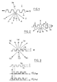
- Figure 1 is a cross sectional view of a first embodiment of a grating structure according to the invention;
- Figure 2 shows a view of a second embodiment of a grating structure according to the invention, similar to figure 1;
- Figure 3 shows a specific grating geometry and parameters according to the invention;
- Figure 4 shows a graph for a 0 order reflectivity of said specific grating designed for high reflectivity;
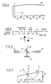
- Figure 5 shows a specific so-called GIRO-geometry chosen for fabrication;
- Figure 6 is a schematic drawing of the measurement set-up used in a specific application of the grating according to the invention; and
- Figure 7 shows an angle-polishing graph of the specific grating samples to avoid interference through multiple reflections.
- The physical mechanism behind grating structures, hereafter called GIRO-grating, standing for GIANT Reflectivity to order O is set out on the basis of a more specific case shown in figure 2 and described hereafter for n2 = 1 (air or vacuum) with normal incidence and a
grating 20 with a rectangular shape and a grating filling factor f=50%. - The highly reflective configuration described above can be designed for TE-polarisation incidence, i.e. incident electric field vector parallel with the grating fringes, as well as for TM-polarisation incidence, i.e. incident magnetic field vector parallel with the grating fringes. The design parameters for structures offering high reflectivity for TE-polarisation will however differ from structures optimised for high reflectivity for TM-polarisation. Therefore, structures optimised for high reflectivity for one polarisation can show relatively low reflectivity for the other polarisation, thereby offering high polarisation selectivity. The approximation made for arriving at the design rules described above are better for TM-polarisation incidence, and consequently designs based on these design rules offer high reflectivity for the TM-polarisation rather than for the TE-polarisation.
- For this specific case, approximate expressions for the required grating parameters have been derived. These approximate expressions were found to agree well with the numerical calculations. Therefore the approximate expression are valuable as a starting point for the optimisation of the grating parameters towards minimum zero order transmission or maximum zero order reflection or a trade-off between those two. The approximate expressions are given by:


- n2 = 1
- Λ = grating pitch
- no, eff= effective index of the first propagating wave in the grating region.
- d = grating depth
- f = grating filling factor and
- λ = vacuum wavelength.
- In the following table 1 we show some results for different cases. The filling factor f is chosen to be 50% in all cases. The optimum values dopt and Λopt listed in this table are optimised through numerical calculations to obtain maximal reflectivity while the approximate values dappr and Λappr are obtained by the expressions listed above.
Table 1 n1 dopt/λ Λopt/λ R0™ dappr/λ Λappr/ λ 2.5 0.443 0.85 0.917718 0.436 0.873 3 0.360 0.670 0.966024 0.3495 0.707 3.5 0.300 0.570 0.999128 0.2916 0.596 4 0.263 0.550 0.952357 0.25 0.516 - This table 1 clearly shows the high zero order reflectivity that can be obtained and shows that the approximate expression predict the optimum parameters quite accurately, typically within 5%. It also shows that the GIRO-effect works at its best for n1 around 3,5 (for f = 50%).
- It is to be noted that a non rectangular shaped grating is shown in figure 1.
- It is further also to be noted that said refractive index n1, resp. n2 can be a complex number.
- One potentially very important application for the GIRO-grating is to use them as a mirror in a vertical cavity surface emitting laser (VCSEL), thereby replacing partly or wholly the normally used mirror being a Bragg quarter-wavelength stack. This can offer major advantages for the performance and fabrication simplicity of such devices.
- In the sequel the invention is described for mirrors based on sub-wavelength gratings, with high reflectivity and polarisation selectivity, called GIRO-grating. The operation and design are explained and illustrated together with their application in VCSEL's. Mirrors based on these gratings would improve the thermal and electrical properties of these components and largely remove the polarisation noise.
- In the sequel, a novel solution is proposed to the problem of dielectric mirrors with high reflectivity. The approach adopted is based on the use of a rectangular, one-
dimensional grating 30. It is shown that these gratings can be designed such that they reflect more than 95% of the incident optical power in a wide variety of material systems. This solution could prove superior to the classical DBR-stack approach for the following reasons: - * In a number of material systems, e.g. InGaASP, refractive index contrasts are low, and the DBR-solution becomes impractical because of the excessive number of DBR-periods required.
- * The grating approach does not introduce additional materials, reducing the problems of differential thermal expansion and mechanical stability.
- * The reflectivity is highly polarisation selective, which is an important advantage in some applications.
- One application with large potential currently envisaged for these GIRO-gratings is incorporation in VCSEL's as top mirror. One of the major difficulties in the current status of VCSEL fabrication, especially for long wavelength components, concerns the realisation of high quality p-type VCSEL-mirrors, resulting from a difficult and fundamental trade-off between optical power absorption and mirror resistance. Current realisations, based on increasing doping levels at semiconductor hetero-interfaces in the mirrors, therefore exhibit high electrical resistance, leading to high VCSEL series resistance and thermal problems, and thereby to degraded VCSEL characteristics.
- Hereinafter it is focused on the design issues of the GIRO-
gratings 30 according to the present embodiment while the reflectivity characteristics of GIRO-grating designed for this application are given still further. - The working scheme of GIRO-gratings is set out, with geometry and notations shown in figure 3. A linearly polarised plane wave with free space wavelength λ is incident on a grating with linear groves with period Λ, layer thickness d, and fill factor f, from a homogeneous medium with refractive index n1. In general, due to diffraction in the grating layer, the incident optical power can couple to the following waves: zero order in transmission (a), higher orders in transmission (b), zero order in reflection (c) and higher orders in reflection (d). A problem consists in how to cancel all unwanted diffraction orders (all except (c)), thereby forcing all optical power to couple to the specular reflection, i.e. beam (c).
- First of all, coupling to higher orders in transmission (b) is suppressed by the choice of a grating period. The choice Λ < λ/n2 wherein n2 is the refractive index of the
lossless transmission medium 2, assures that all but the zero orders in transmission are evanescent, and therefore carry no optical power. Coupling to zero order in transmission is prevented, by assuring that the optical field has a zero average atinterface 2, by adjusting the grating thickness such that the two present propagating modes are in anti-phase at this interface. Similarly, the grating parameters are chosen such that after reflection atinterface 2, the backpropagating field interferes constructively with the primary reflection atinterface 1, and the total reflected field exhibits a constant phase, thereby preventing coupling to uneven diffraction orders. This mechanism and the compromise to be taken in the GIRO-design is further clarified hereafter. - For given material parameters n1 and n2, the grating period is chosen such that only three propagation modes are supported in the grating regions, with respective field profiles ψ0(x), ψ1(x) and ψ2(x) and effective indices ne,0, ne,1 and ne,3. Due to the uneven symmetry of
mode 1, no optical power is coupled from the incident beam to this mode. - In order to arrive at relatively simple analytical design rules, the following approximations are made:
- * Modal profiles for zero and second order modes are approximated as shown in figure 3.
- * Reflection at interfaces is treated as a local phenomenon, i.e. at each point a local reflection coefficient r and transmission coefficient t is used. These coefficients are given by the Fresnel coefficients for reflection and transmission at plane interfaces for plane waves incidence.
- Expressing that the fields ψ2 has a zero average, leads immediately to


- In the following discussion, we set m=0 and m=2.
- Given the fact that for proper operation of the GIRO-grating, the zero order mode should be concentrated in the grating material n1, and therefore strongly guided, with ne,0 >> n1 and the second order mode should be concentrated in the material with refractive index n2, following approximations can be found:

- With these values for the effective indices of the propagating modes, the system of equations is over specified, and is only solvable if

- Allowing a phase error ϕ between the modes arriving at
interface 2, and consequently a 2ϕ phase error atinterface 1, we arrive at the following set of design rules, applicable to any combinations of n1 and n2:
- In view of the approximations used to arrive at the design rules given in the previous section, designs based on this approach are evaluated in this section directed on a comparison with rigorous modelling. A rigorous diffraction model based on RCWA (Rigorous Coupled Wave Analysis) is used to predict the coupling of optical power to zero order in reflection for TM-polarisation, i.e. electrical fields perpendicular to grating grooves. Here a semiconductor-air grating was modelled (n2=1) with a filling factor of 50%. For a number of substrate materials, optimum values for d/λ and Λ/λ were derived using iteration through the RCWA based model, using the design rules as a starting configuration.
- RCWA results are given in table 2 hereafter wherein the subscript "appr" refers to the start values and optimum values are indicated with the subscript "opt". The fraction of the incident optical power coupled to the desired zero order in reflection is given for the optimum parameter set. Table 2 shows a comparison of GIRO-grating design based on expressions presented herein and optimisation based on RCWA.
- From table 2, one can conclude that the optimum parameter set for the GIRO-grating is predicted quite well by the design rules, and that indeed reflection values exceed 90%. For the particularly interesting case of n1=3,5 which is close to the refractive index in GaAs for the 1µm wavelength range but also to the refractive index of InGaAsP for long wavelength applications, this reflection even exceeds 99,5%.
Table 2 n 1 (d/λ) appr (Λ/λ) appr (d/λ) opt (Λ/λ) opt R™ 2.5 0.4360 0.873 0.443 0.850 0.9177 3.0 0.3495 0.707 0.360 0.670 0.9660 3.5 0.2916 0.596 0.300 0.570 0.9991 4.0 0.2500 0.516 0.263 0.550 0.9524 - An example is given hereafter. As already mentioned in the introductory part above, an important application of the GIRO-gratings is the use of these diffractive structures as VCSEL-top mirror. Especially for long wavelength VCSELs, due to the low refractive index contrast available in the InGaAsP material system, this approach seems quite attractive. Based on the design rules given in a previous section, a GIRO-grating has been designed for high reflectivity centred at λ= 1,55µm. The grating layer itself consists of a 50% grating etched into a quaternary layer (λg = 1,3µm, n = 3,49) and the substrate material is InP (n = 3,176). Parameters of the optimised GIRO-grating are: grating period 930 nm, grating depth 465 nm and
grating fill factor 50%. - Reflectivity for the TM and TE zero orders are shown in figure 4 with results obtained by RCWA modelling. The TM-reflectivity amounts to 99,9% while the TE-reflectivity is as low as 2,0%. This indicates that the use of GIRO-gratings also may offer a possibility to solve the VCSEL-problem of polarisation instability.
- Hereinafter, there is described the fabrication and experimental evaluation of GIRO-gratings, designed for operation at a wavelength of 10,6 µm, which is the wavelength range of CO2-lasers, with reference to figure 5.
- The results discussed here relate to the first experimental realisation of GIRO-gratings.
- The so-called GIRO structure for operation at a wavelength of 10,6 µm is set out hereafter. In view of the relatively easy fabrication geometry as depicted in Fig. 5 was adopted to realise GIRO-gratings for λ = 10,6 µm. The component consists of a
linear grating 50, withrectangular grooves 53, etched into a GaAs substrate 51. The geometry is designed such that the zero-order reflectivity for on-axis incidence is maximised for a TM-polarised plane wave whereby TM-polarisation means incidentelectrical field vector 54 perpendicular to thegrating grooves 53. This plane wave is incident from the substrate side 51, and is consequently reflected back 55 into the substrate 51. - Based on the design rules described in (REF) and taken into account the geometry depicted in Fig. 5, GIRO-gratings were optimised, resulting in the optimum parameter set given in Table 3. Grating filling factor f is defined as the percentage of grating material in one grating period.
Table 3 Parameter Value wavelength of operation (λ) 10,6 µm substrate material : GaAs refractive index = 3,27 at λ=10,6 µm grating period (Λ) 7µm grating filling factor (f) 3/7 grating depth (d) 3,5µm maximum TM-reflectivity 99,8% - In view of the technology used to realise these GIRO-gratings, some of these parameters were changed to simplify the production of these components and hence increase the component yield. Taking into account these technological limitations mainly due to the optical contact lithography used, we arrived at four grating designs with parameters given in Table 4, compatible with the fabrication method used. In said table 4, parameters of the realised GIRO-gratings are thus set out with the operation being 10,6µm and substrate material GaAs.
Table 4 PARAMETER GIRO 1 GIRO 2GIRO 3 GIRO 4 grating period (Λ) 6µm 6 µm 7µm 8µm grating filling factor f 2/6 3/6 3/7 3/8 grating depth (d) 3,5µm 3,5µm 3,5µm 3,5µm Maximum TM-reflectivity (theoretical) 99,4% 98,7% 99,8% 99,1% - Hereafter there is described more in detail a GIRO-grating fabrication process in a specific example:
- substrate material
The GIRO-gratings are realised in GaAs. In order to avoid substrate absorption, e.g. through free carrier absorption, undoped material is used. Prior to further processing, the substrates are cleaned to ensure reproductible and reliable component realisation. - Deposition of SiO2
A layer of 200 nm SiO2 is deposited, e.g. by plasma deposition. This layer serves as mask during the semiconductor etching process. The processing steps are summarised below. - Application of photoresist layer
- pattern definition in photoresist
Photoresist is UV-illuminated through a mask plate such as Chromium features on glass, using contact lithography. Developing this photoresist layer transfers the pattern of the mask into the photoresist layer. - pattern definition in the SiO2-layer
Since the photoresist layer can not withstand the semiconductor etching process, an intermediate mask level is used. The photoresist pattern is transferred into a SiO2-layer by plasma etching. - pattern definition in the GaAs substrate
Using the combined photoresist and SiO2 mask, the GaAs material is etched (the process used in Reactive Ion Etching with SiCl4). - stripping of residues (a.o. photoresist and SiO2)
By applying an oxygen plasma etch, unwanted etching residues are removed. - The experimental evaluation methodology is set out hereafter.
- For the experimental evaluation of the realised structures, a set-up as schematically shown in Fig. 6 was used. A CO2-laser beam 64 is incident upon a
beam splitter 61. Part of the optical power is coupled directly to adetector 62 for calibration purposes, and the other part is coupled to anotherdetector 63 after reflection on thesample 60. - In order to facilitate the measurements, the backside of the samples are angle-polished, as shown in figure 7, e.g. with a typical polishing angle of 3,5°. This approach allow separate measurement of frontside and backside sample reflectivity, while avoiding interference through multiple reflections inside the GIRO-
sample 70, which would severely complicate the measurement interpretation. Measuring the optical power in the frontside and backside primary reflected beams 71, resp. 72, in combination with monitoring the incident optical power, allows to derive the GIRO-grating reflectivity in absolute terms 73.
Claims (24)
- System for transferring a beam of electromagnetic radiation having a vacuum wavelength, said system comprising:a first dielectric medium (1) with a first refractive index n1 wherein said beam can propagate;a second dielectric medium (2) with a second refractive index n2 ; anda dielectric layer (10) inbetween said first and said second medium,characterised in that said layer has a periodicity of the dielectric properties parallel to said layer, said periodicity having a period that is smaller than the wavelength of the electromagnetic radiation in said second dielectric medium (2), said dielectric properties and said periodicity (Λ) of said dielectric layer (10) further being chosen such that their parameter cooperatively establish that said beam when incident on said dielectric layer (10) is reflected for essentially 100% into the specular zero-order reflection.
- System as recited in claim 1, characterised in that said dielectric layer has a sufficiently large variation of said dielectric properties within one repetition of said period such that said beam when incident on said dielectric layer excites at least two propagating modes within said layer.
- System as recited in claim 2, characterised in that said beam is substantially orthogonal incident on said dielectric layer.
- System as recited in claim 1, characterised in that said dielectric layer has a periodicity of the dielectric properties in a plurality of directions, said periodicity having a period for each of said directions that is smaller than the wavelength of the electromagnetic radiation in said second dielectric medium (2).
- System as recited in claim 1, characterised in that said dielectric layer (10, 20, ..., 70) is a grating.
- System according to the preceding claim, characterised in that said grating is a grated surface structure of the second dielectric medium (2), said dielectric layer being composed of the same material as said second medium (2).
- System according to one of the claims 5 or 6, characterised in that said grating (10,... ) has a one dimensional periodicity (Λ).
- System according to one of the claims 5 to 7, characterised in that a TM-polarisation mode of the incident wave is set.
- System according to one of the claims 5 to 7, characterised in that a TE-polarisation mode of the incident wave is set.
- System according to any of the claims 5 to 9, characterised in that said grating (20,30,50) has a substantially rectangular cross section.
- System according to any of the claims 5 to 10, characterised in that said grating has a grating filling factor (f) which is comprised between 40 and 60%, preferably approximately 50%.
- System according to any of the claims 5 to 11, characterised in that the second medium (2) referred to the propagating direction of said beam , is formed by air or vacuum with a second refractive index n2 approximately to unity.
- System according to any of the claims 5 to 12, characterised in that the arrangement thereof is such that the angle of incidence of the incident wave is substantially normal to the grating.
- System according to any of the claims 5 to 13, characterised in that the grating parameters are chosen so as to be comprised within a minimum zero order transmission and a maximum zero order reflection or a trade-off between those two and wherein they are generated by the following expressions


 n2 = 1Λ=grating pitchn0,eff = effective index of the first propagating wave in the grating region,d = grating depthf = grating filing factorλ = vacuum wavelength.
 - System according to the preceding claim, characterised in that the first refractive index n1 is chosen so as to be comprised within a range between 3 and 4, preferably approximately 3,5.
- System according to any one of the preceding claims, characterised in that said refractive index n1, resp. n2 is a complex number.
- System according to anyone of the preceding claims, characterised in that said dielectric layer is used as a mirror.
- System according to the preceding claim, characterised in that a giant reflective zero order grating (30) is used as a mirror in a vertical cavity surface emitting laser (VCSEL).
- System according to one of the claims 17 or 18, characterised in that there is provided a one dimensional grating (30) with a dielectric mirrors with high reflectivity, substantially rectangular, without introducing additional materials.
- System according to one of the claims 17 to 19, characterised in that said grating (30) is provided with substantially linear grooves (33) from a homogeneous medium with reflective index (n1) and wherein the selection of the grating period is such that coupling to higher orders in transmission is suppressed, wherein the grating thickness is selected such that the two present propagating modes are in anti-phase after propagation through the grating layer, the backpropagating field interfering constructively with the primary reflection at interface (1), and the total reflected field exhibiting a constant phase.
- System as recited in the preceding claim, characterised in that said dielectric layer is one of the mirrors in a laser cavity, said electromagnetic radiation being visible light or infra-red or ultra-violet light.
- System as recited in the preceding claim, characterised in that said laser is a vertical cavity surface emitting laser VCSEL laser.
- System as recited in any one the claims 1 to 16, characterised in that said first and second medium form together a dielectric system which is used for microwave applications, said electromagnetic radiation being in the range of microwave radiation.
- System as recited in the preceding claim, characterised in that said dielectric system is integrated in microwave antenna's.
Applications Claiming Priority (4)
| Application Number | Priority Date | Filing Date | Title |
|---|---|---|---|
| BE9600280 | 1996-03-29 | ||
| BE9600280A BE1010069A6 (en) | 1996-03-29 | 1996-03-29 | Optical system with high reflectivity grid |
| US1645496P | 1996-04-29 | 1996-04-29 | |
| US16454 | 1996-04-29 |
Publications (3)
| Publication Number | Publication Date |
|---|---|
| EP0798574A2 true EP0798574A2 (en) | 1997-10-01 |
| EP0798574A3 EP0798574A3 (en) | 1998-09-02 |
| EP0798574B1 EP0798574B1 (en) | 2008-05-14 |
Family
ID=3889642
Family Applications (1)
| Application Number | Title | Priority Date | Filing Date |
|---|---|---|---|
| EP97870045A Expired - Lifetime EP0798574B1 (en) | 1996-03-29 | 1997-04-01 | Optical system with a dielectric subwavelength structure having a high reflectivity and polarisation selectivity |
Country Status (4)
| Country | Link |
|---|---|
| US (1) | US6191890B1 (en) |
| EP (1) | EP0798574B1 (en) |
| BE (1) | BE1010069A6 (en) |
| DE (1) | DE69738679D1 (en) |
Cited By (10)
| Publication number | Priority date | Publication date | Assignee | Title |
|---|---|---|---|---|
| WO2001005008A1 (en) * | 1999-07-10 | 2001-01-18 | Qinetiq Limited | Control of polarisation of vertical cavity surface emitting lasers |
| WO2001009650A2 (en) * | 1999-08-02 | 2001-02-08 | Universite Jean Monnet | Optical polarizing device and laser polarisation device |
| WO2002025781A2 (en) * | 2000-09-21 | 2002-03-28 | Ut-Battelle, Llc | Micro-laser |
| US6680799B1 (en) | 1999-08-02 | 2004-01-20 | Universite Jean Monnet | Optical polarizing device and laser polarization device |
| EP1868015A1 (en) * | 1999-08-02 | 2007-12-19 | Universite Jean Monnet | Optical polarizing device and laser polarisation device |
| US7333522B2 (en) | 2003-11-18 | 2008-02-19 | Ulm-Photonics | Polarization control of vertical diode lasers by monolithically integrated surface grating |
| EP2141519A1 (en) | 2008-07-04 | 2010-01-06 | Université Jean-Monnet | Diffractive polarizing mirror device |
| EP2190082A3 (en) * | 2008-11-21 | 2011-04-20 | Vertilas GmbH | Surface emitting semi-conductor laser diode and method for manufacturing the same |
| FR2979436A1 (en) * | 2011-08-29 | 2013-03-01 | Commissariat Energie Atomique | REFLECTOR DEVICE FOR REAR FRONT OF OPTICAL DEVICES |
| US9306290B1 (en) * | 2007-05-31 | 2016-04-05 | Foersvarets Materielverk | Controller barrier layer against electromagnetic radiation |
Families Citing this family (55)
| Publication number | Priority date | Publication date | Assignee | Title |
|---|---|---|---|---|
| US7167615B1 (en) * | 1999-11-05 | 2007-01-23 | Board Of Regents, The University Of Texas System | Resonant waveguide-grating filters and sensors and methods for making and using same |
| US8111401B2 (en) * | 1999-11-05 | 2012-02-07 | Robert Magnusson | Guided-mode resonance sensors employing angular, spectral, modal, and polarization diversity for high-precision sensing in compact formats |
| US7065124B2 (en) * | 2000-11-28 | 2006-06-20 | Finlsar Corporation | Electron affinity engineered VCSELs |
| US6905900B1 (en) * | 2000-11-28 | 2005-06-14 | Finisar Corporation | Versatile method and system for single mode VCSELs |
| US6990135B2 (en) * | 2002-10-28 | 2006-01-24 | Finisar Corporation | Distributed bragg reflector for optoelectronic device |
| TWI227799B (en) * | 2000-12-29 | 2005-02-11 | Honeywell Int Inc | Resonant reflector for increased wavelength and polarization control |
| US6836501B2 (en) * | 2000-12-29 | 2004-12-28 | Finisar Corporation | Resonant reflector for increased wavelength and polarization control |
| WO2003025635A1 (en) * | 2001-09-19 | 2003-03-27 | Technion Research & Development Foundation Ltd. | Space-variant subwavelength dielectric grating and applications thereof |
| US6747799B2 (en) * | 2001-11-12 | 2004-06-08 | Pts Corporation | High-efficiency low-polarization-dependent-loss lamellar diffraction-grating profile and production process |
| US6876784B2 (en) * | 2002-05-30 | 2005-04-05 | Nanoopto Corporation | Optical polarization beam combiner/splitter |
| US20040047039A1 (en) * | 2002-06-17 | 2004-03-11 | Jian Wang | Wide angle optical device and method for making same |
| US7283571B2 (en) * | 2002-06-17 | 2007-10-16 | Jian Wang | Method and system for performing wavelength locking of an optical transmission source |
| JP4310080B2 (en) * | 2002-06-17 | 2009-08-05 | キヤノン株式会社 | Diffractive optical element and optical system and optical apparatus provided with the same |
| US7386205B2 (en) * | 2002-06-17 | 2008-06-10 | Jian Wang | Optical device and method for making same |
| EP1520203A4 (en) | 2002-06-18 | 2005-08-24 | Nanoopto Corp | Optical components exhibiting enhanced functionality and method of making same |
| JP2005534981A (en) | 2002-08-01 | 2005-11-17 | ナノオプト コーポレーション | Precision phase lag device and method of manufacturing the same |
| US7064899B2 (en) * | 2002-08-30 | 2006-06-20 | Digital Optics Corp. | Reduced loss diffractive structure |
| US6965626B2 (en) * | 2002-09-03 | 2005-11-15 | Finisar Corporation | Single mode VCSEL |
| US7190521B2 (en) * | 2002-09-13 | 2007-03-13 | Technion Research And Development Foundation Ltd. | Space-variant subwavelength dielectric grating and applications thereof |
| US6661830B1 (en) | 2002-10-07 | 2003-12-09 | Coherent, Inc. | Tunable optically-pumped semiconductor laser including a polarizing resonator mirror |
| US6920272B2 (en) * | 2002-10-09 | 2005-07-19 | Nanoopto Corporation | Monolithic tunable lasers and reflectors |
| US7013064B2 (en) * | 2002-10-09 | 2006-03-14 | Nanoopto Corporation | Freespace tunable optoelectronic device and method |
| US6813293B2 (en) * | 2002-11-21 | 2004-11-02 | Finisar Corporation | Long wavelength VCSEL with tunnel junction, and implant |
| US7139128B2 (en) * | 2003-01-06 | 2006-11-21 | Polychromix Corporation | Diffraction grating having high throughput efficiency |
| US7268946B2 (en) * | 2003-02-10 | 2007-09-11 | Jian Wang | Universal broadband polarizer, devices incorporating same, and method of making same |
| KR101162135B1 (en) * | 2003-03-13 | 2012-07-03 | 아사히 가라스 가부시키가이샤 | Diffraction element and optical device |
| US20040222363A1 (en) * | 2003-05-07 | 2004-11-11 | Honeywell International Inc. | Connectorized optical component misalignment detection system |
| US20040247250A1 (en) * | 2003-06-03 | 2004-12-09 | Honeywell International Inc. | Integrated sleeve pluggable package |
| US20040258355A1 (en) * | 2003-06-17 | 2004-12-23 | Jian Wang | Micro-structure induced birefringent waveguiding devices and methods of making same |
| US7277461B2 (en) * | 2003-06-27 | 2007-10-02 | Finisar Corporation | Dielectric VCSEL gain guide |
| US7075962B2 (en) * | 2003-06-27 | 2006-07-11 | Finisar Corporation | VCSEL having thermal management |
| US6961489B2 (en) * | 2003-06-30 | 2005-11-01 | Finisar Corporation | High speed optical system |
| US7149383B2 (en) * | 2003-06-30 | 2006-12-12 | Finisar Corporation | Optical system with reduced back reflection |
| US20060056762A1 (en) * | 2003-07-02 | 2006-03-16 | Honeywell International Inc. | Lens optical coupler |
| US7210857B2 (en) * | 2003-07-16 | 2007-05-01 | Finisar Corporation | Optical coupling system |
| US20050013542A1 (en) * | 2003-07-16 | 2005-01-20 | Honeywell International Inc. | Coupler having reduction of reflections to light source |
| US20050013539A1 (en) * | 2003-07-17 | 2005-01-20 | Honeywell International Inc. | Optical coupling system |
| US6887801B2 (en) * | 2003-07-18 | 2005-05-03 | Finisar Corporation | Edge bead control method and apparatus |
| US7031363B2 (en) * | 2003-10-29 | 2006-04-18 | Finisar Corporation | Long wavelength VCSEL device processing |
| US7829912B2 (en) * | 2006-07-31 | 2010-11-09 | Finisar Corporation | Efficient carrier injection in a semiconductor device |
| US7920612B2 (en) * | 2004-08-31 | 2011-04-05 | Finisar Corporation | Light emitting semiconductor device having an electrical confinement barrier near the active region |
| US7596165B2 (en) * | 2004-08-31 | 2009-09-29 | Finisar Corporation | Distributed Bragg Reflector for optoelectronic device |
| US7859753B2 (en) * | 2005-12-21 | 2010-12-28 | Chem Image Corporation | Optical birefringence filters with interleaved absorptive and zero degree reflective polarizers |
| US7992361B2 (en) * | 2006-04-13 | 2011-08-09 | Sabic Innovative Plastics Ip B.V. | Polymer panels and methods of making the same |
| US8590271B2 (en) * | 2006-04-13 | 2013-11-26 | Sabic Innovative Plastics Ip B.V. | Multi-wall structural components having enhanced radiatransmission capability |
| US20070242715A1 (en) * | 2006-04-18 | 2007-10-18 | Johan Gustavsson | Mode and polarization control in vcsels using sub-wavelength structure |
| US8031752B1 (en) | 2007-04-16 | 2011-10-04 | Finisar Corporation | VCSEL optimized for high speed data |
| DE102007033567A1 (en) | 2007-07-19 | 2009-04-09 | Trumpf Laser- Und Systemtechnik Gmbh | Phase shift device and laser resonator for generating radially or azimuthally polarized laser radiation |
| US8126694B2 (en) * | 2008-05-02 | 2012-02-28 | Nanometrics Incorporated | Modeling conductive patterns using an effective model |
| DE102008030374B4 (en) | 2008-06-26 | 2014-09-11 | Trumpf Laser- Und Systemtechnik Gmbh | Method of laser cutting and CO2 laser cutting machine |
| US9357240B2 (en) | 2009-01-21 | 2016-05-31 | The Nielsen Company (Us), Llc | Methods and apparatus for providing alternate media for video decoders |
| US8270814B2 (en) | 2009-01-21 | 2012-09-18 | The Nielsen Company (Us), Llc | Methods and apparatus for providing video with embedded media |
| FR2945159B1 (en) * | 2009-04-29 | 2016-04-01 | Horiba Jobin Yvon Sas | REFLECTIVE METAL DIFFRACTION NETWORK HAVING A HIGH FLOW OF FEMTOSECOND FLOW, SYSTEM COMPRISING SUCH A NETWORK AND METHOD FOR IMPROVING THE DAMAGE THRESHOLD OF A METAL DIFFRACTION NETWORK |
| US20110085232A1 (en) * | 2009-10-08 | 2011-04-14 | The Penn State Research Foundation | Multi-spectral filters, mirrors and anti-reflective coatings with subwavelength periodic features for optical devices |
| JP6811448B2 (en) * | 2016-09-14 | 2021-01-13 | 日本電気株式会社 | Grating coupler |
Citations (1)
| Publication number | Priority date | Publication date | Assignee | Title |
|---|---|---|---|---|
| US5255278A (en) * | 1991-07-10 | 1993-10-19 | Nec Corporation | Semiconductor laser with vertical resonator |
Family Cites Families (6)
| Publication number | Priority date | Publication date | Assignee | Title |
|---|---|---|---|---|
| JPS58174906A (en) * | 1982-04-07 | 1983-10-14 | Ricoh Co Ltd | Method for preventing surface reflection of optical element |
| EP0322714B1 (en) * | 1987-12-24 | 1996-09-11 | Kuraray Co., Ltd. | Polarizing optical element and device using the same |
| JPH02178604A (en) * | 1988-12-28 | 1990-07-11 | Kuraray Co Ltd | Cross diffraction grating and polarized wave rotation detecting device using same |
| JPH09500459A (en) * | 1994-05-02 | 1997-01-14 | フィリップス エレクトロニクス ネムローゼ フェンノートシャップ | Light transmitting optical element having anti-reflection diffraction grating |
| US5598300A (en) * | 1995-06-05 | 1997-01-28 | Board Of Regents, The University Of Texas System | Efficient bandpass reflection and transmission filters with low sidebands based on guided-mode resonance effects |
| US5726805A (en) * | 1996-06-25 | 1998-03-10 | Sandia Corporation | Optical filter including a sub-wavelength periodic structure and method of making |
-
1996
- 1996-03-29 BE BE9600280A patent/BE1010069A6/en not_active IP Right Cessation
-
1997
- 1997-03-31 US US08/829,348 patent/US6191890B1/en not_active Expired - Lifetime
- 1997-04-01 EP EP97870045A patent/EP0798574B1/en not_active Expired - Lifetime
- 1997-04-01 DE DE69738679T patent/DE69738679D1/en not_active Expired - Lifetime
Patent Citations (1)
| Publication number | Priority date | Publication date | Assignee | Title |
|---|---|---|---|---|
| US5255278A (en) * | 1991-07-10 | 1993-10-19 | Nec Corporation | Semiconductor laser with vertical resonator |
Non-Patent Citations (9)
| Title |
|---|
| BARKESHLI S ET AL: "ON THE ANALYSIS AND DESIGN OF THE FREQUENCY SELECTIVE SURFACE FOR THE N-STAR SATELLITE KU/S-SHAPED REFLECTOR" IEEE ANTENNAS AND PROPAGATION SOCIETY INTERNATIONAL SYMPOSIUM DIGEST, NEWPORT BEACH, JUNE 18 - 23, 1995 HELD IN CONJUNCTION WITH THE USNC/URSI NATIONAL RADIO SCIENCE MEETI, vol. VOL. 3, 18 June 1995, INSTITUTE OF ELECTRICAL AND ELECTRONICS ENGINEERS, pages 1656-1658, XP000588814 * |
| CHOU S Y ET AL: "SUBWAVELENGTH AMORPHOUS SILICON TRANSMISSION GRATINGS AND APPLICATIONS IN POLARIZERS AND WAVEPLATES" APPLIED PHYSICS LETTERS, vol. 67, no. 6, 7 August 1995, pages 742-744, XP000521184 * |
| COSTA J C W A ET AL: "ANALYSIS OF THE SELECTIVE BEHAVIOR OF MULTILAYER STRUCTURES WITH A DIELECTRIC GRATING" IEEE TRANSACTIONS ON ANTENNAS AND PROPAGATION, vol. 43, no. 5, 1 May 1995, pages 529-533, XP000505291 * |
| E.B.GRANN, M.G.MOHARAM, D.A.POMMET: "Artificial uniaxial and biaxial dielectrics with use of a two-dimensional subwavelegth binary gratings." J.OPT.SOC.AM.A, vol. 11, no. 10, October 1994, pages 2695-2703, XP002070085 * |
| H.L. BERTONI, L.S. CHEO, T.TAMIR: "Frequency selective Reflective and transmission by a Periodic dielectric layer." IEEE TRANSACTION ON ANTENNAS AND PROPAGATION, vol. 37, no. 1, 1 January 1989, pages 78-83, XP002070018 * |
| HAVA S ET AL: "SILICON GRATING-BASED MIRROR FOR 1.3- M POLARIZED BEAMS: MATLAB-AIDED DESIGN" APPLIED OPTICS, vol. 34, no. 6, 20 February 1995, pages 1053-1058, XP000490007 * |
| JARI TURUNEN ET AL: "BRAGG HOLOGRAMS WITH BINARY SYNTHETIC SURFACE-RELIEF PROFILE" OPTICS LETTERS, vol. 18, no. 12, 15 June 1993, pages 1022-1024, XP000345918 * |
| MAGNUSSON R ET AL: "NEW PRINCIPLE FOR OPTICAL FILTERS" APPLIED PHYSICS LETTERS, vol. 61, no. 9, 31 August 1992, pages 1022-1024, XP000294445 * |
| WANG S S; MAGNUSSON R: 'MULTILAYER WAVEGUIDE-GRATING FILTERS' APPLIED OPTICS, OSA, OPTICAL SOCIETY OF AMERICA 10 May 1995, WASHINGTON, DC, US, pages 2414 - 2420, XP000511437 * |
Cited By (16)
| Publication number | Priority date | Publication date | Assignee | Title |
|---|---|---|---|---|
| WO2001005008A1 (en) * | 1999-07-10 | 2001-01-18 | Qinetiq Limited | Control of polarisation of vertical cavity surface emitting lasers |
| US6785320B1 (en) | 1999-07-10 | 2004-08-31 | Qinetiq Limited | Control of polarisation of vertical cavity surface emitting lasers |
| WO2001009650A2 (en) * | 1999-08-02 | 2001-02-08 | Universite Jean Monnet | Optical polarizing device and laser polarisation device |
| WO2001009650A3 (en) * | 1999-08-02 | 2001-08-09 | Univ Jean Monnet | Optical polarizing device and laser polarisation device |
| US6680799B1 (en) | 1999-08-02 | 2004-01-20 | Universite Jean Monnet | Optical polarizing device and laser polarization device |
| EP1868015A1 (en) * | 1999-08-02 | 2007-12-19 | Universite Jean Monnet | Optical polarizing device and laser polarisation device |
| WO2002025781A2 (en) * | 2000-09-21 | 2002-03-28 | Ut-Battelle, Llc | Micro-laser |
| WO2002025781A3 (en) * | 2000-09-21 | 2003-12-24 | Ut Battelle Llc | Micro-laser |
| US7333522B2 (en) | 2003-11-18 | 2008-02-19 | Ulm-Photonics | Polarization control of vertical diode lasers by monolithically integrated surface grating |
| US9306290B1 (en) * | 2007-05-31 | 2016-04-05 | Foersvarets Materielverk | Controller barrier layer against electromagnetic radiation |
| EP2141519A1 (en) | 2008-07-04 | 2010-01-06 | Université Jean-Monnet | Diffractive polarizing mirror device |
| US8238025B2 (en) | 2008-07-04 | 2012-08-07 | Olivier Parriaux | Diffractive polarizing mirror device |
| EP2190082A3 (en) * | 2008-11-21 | 2011-04-20 | Vertilas GmbH | Surface emitting semi-conductor laser diode and method for manufacturing the same |
| US8331412B2 (en) | 2008-11-21 | 2012-12-11 | Vertilas Gmbh | Vertical-cavity surface-emitting semiconductor laser diode and method for the manufacture thereof |
| FR2979436A1 (en) * | 2011-08-29 | 2013-03-01 | Commissariat Energie Atomique | REFLECTOR DEVICE FOR REAR FRONT OF OPTICAL DEVICES |
| WO2013030482A1 (en) * | 2011-08-29 | 2013-03-07 | Commissariat A L'energie Atomique Et Aux Energies Alternatives | Reflector device for rear face of optical devices |
Also Published As
| Publication number | Publication date |
|---|---|
| EP0798574A3 (en) | 1998-09-02 |
| BE1010069A6 (en) | 1997-12-02 |
| EP0798574B1 (en) | 2008-05-14 |
| US6191890B1 (en) | 2001-02-20 |
| DE69738679D1 (en) | 2008-06-26 |
Similar Documents
| Publication | Publication Date | Title |
|---|---|---|
| EP0798574A2 (en) | Optical system with a dielectric subwavelength structure having a high reflectivity and polarisation selectivity | |
| Sharon et al. | Narrow spectral bandwidths with grating waveguide structures | |
| Palamaru et al. | Photonic crystal waveguides: Out-of-plane losses and adiabatic modal conversion | |
| Lalanne et al. | Bloch-wave engineering for high-Q, small-V microcavities | |
| EP2715417B1 (en) | Planar grating polarization transformer | |
| US6436613B1 (en) | Integrated hybrid optoelectronic devices | |
| Wagatsuma et al. | Mode conversion and optical filtering of obliquely incident waves in corrugated waveguide filters | |
| US6680799B1 (en) | Optical polarizing device and laser polarization device | |
| US8442374B2 (en) | Ultra-low loss hollow core waveguide using high-contrast gratings | |
| US6785320B1 (en) | Control of polarisation of vertical cavity surface emitting lasers | |
| WO2002025336A2 (en) | Transverse-longitudinal integrated resonator | |
| Dems | Monolithic high-contrast gratings: Why do they not scatter light? | |
| US7020373B2 (en) | Antireflective coating structure for photonic crystal and method for forming antireflective coating structure | |
| Zheng et al. | High reflectivity broadband infrared mirrors with all dielectric subwavelength gratings | |
| Schmid et al. | Subwavelength grating structures in planar waveguide facets for modified reflectivity | |
| Davanço et al. | Detailed characterization of slow and dispersive propagation near a mini-stop-band of an InP photonic crystal waveguide. | |
| Kawashima et al. | Photonic crystal polarization beam splitters and their applications: first industrialization of photonic crystal devices | |
| JP2004505309A (en) | Optical waveguide filter | |
| Berger et al. | Finite-element Maxwell’s equations modeling of etched air/dielectric Bragg mirrors | |
| Kleckner et al. | Design, fabrication, and characterization of deep-etched waveguide gratings | |
| EP1198726B1 (en) | Optical polarizing device and laser polarisation device | |
| Forouhar et al. | Performance and limitations of chirped grating lenses of Ti-indiffused LiNbO 3 planar waveguides | |
| JP7438283B2 (en) | Heterogeneously integrated photonic platform with nonlinear frequency conversion elements | |
| EP1868015B1 (en) | Optical polarizing device and laser polarisation device | |
| März et al. | 16 Planar high index-contrast photonic crystals for telecom applications |
Legal Events
| Date | Code | Title | Description |
|---|---|---|---|
| PUAI | Public reference made under article 153(3) epc to a published international application that has entered the european phase |
Free format text: ORIGINAL CODE: 0009012 |
|
| AK | Designated contracting states |
Kind code of ref document: A2 Designated state(s): BE DE FR GB IT NL SE |
|
| PUAL | Search report despatched |
Free format text: ORIGINAL CODE: 0009013 |
|
| AK | Designated contracting states |
Kind code of ref document: A3 Designated state(s): BE DE FR GB IT NL SE |
|
| 17P | Request for examination filed |
Effective date: 19990225 |
|
| 17Q | First examination report despatched |
Effective date: 20020923 |
|
| RIC1 | Information provided on ipc code assigned before grant |
Ipc: 7H 01S 3/085 A |
|
| GRAP | Despatch of communication of intention to grant a patent |
Free format text: ORIGINAL CODE: EPIDOSNIGR1 |
|
| RIC1 | Information provided on ipc code assigned before grant |
Ipc: H01S 5/183 20060101ALI20070516BHEP Ipc: G02B 5/18 20060101AFI20070516BHEP |
|
| GRAS | Grant fee paid |
Free format text: ORIGINAL CODE: EPIDOSNIGR3 |
|
| GRAA | (expected) grant |
Free format text: ORIGINAL CODE: 0009210 |
|
| AK | Designated contracting states |
Kind code of ref document: B1 Designated state(s): BE DE FR GB IT NL SE |
|
| REG | Reference to a national code |
Ref country code: GB Ref legal event code: FG4D |
|
| REF | Corresponds to: |
Ref document number: 69738679 Country of ref document: DE Date of ref document: 20080626 Kind code of ref document: P |
|
| NLV1 | Nl: lapsed or annulled due to failure to fulfill the requirements of art. 29p and 29m of the patents act | ||
| PG25 | Lapsed in a contracting state [announced via postgrant information from national office to epo] |
Ref country code: NL Free format text: LAPSE BECAUSE OF FAILURE TO SUBMIT A TRANSLATION OF THE DESCRIPTION OR TO PAY THE FEE WITHIN THE PRESCRIBED TIME-LIMIT Effective date: 20080514 |
|
| PG25 | Lapsed in a contracting state [announced via postgrant information from national office to epo] |
Ref country code: SE Free format text: LAPSE BECAUSE OF FAILURE TO SUBMIT A TRANSLATION OF THE DESCRIPTION OR TO PAY THE FEE WITHIN THE PRESCRIBED TIME-LIMIT Effective date: 20080814 |
|
| PG25 | Lapsed in a contracting state [announced via postgrant information from national office to epo] |
Ref country code: BE Free format text: LAPSE BECAUSE OF FAILURE TO SUBMIT A TRANSLATION OF THE DESCRIPTION OR TO PAY THE FEE WITHIN THE PRESCRIBED TIME-LIMIT Effective date: 20080514 |
|
| PLBE | No opposition filed within time limit |
Free format text: ORIGINAL CODE: 0009261 |
|
| STAA | Information on the status of an ep patent application or granted ep patent |
Free format text: STATUS: NO OPPOSITION FILED WITHIN TIME LIMIT |
|
| 26N | No opposition filed |
Effective date: 20090217 |
|
| PG25 | Lapsed in a contracting state [announced via postgrant information from national office to epo] |
Ref country code: IT Free format text: LAPSE BECAUSE OF FAILURE TO SUBMIT A TRANSLATION OF THE DESCRIPTION OR TO PAY THE FEE WITHIN THE PRESCRIBED TIME-LIMIT Effective date: 20080514 |
|
| PGFP | Annual fee paid to national office [announced via postgrant information from national office to epo] |
Ref country code: GB Payment date: 20140327 Year of fee payment: 18 |
|
| PGFP | Annual fee paid to national office [announced via postgrant information from national office to epo] |
Ref country code: DE Payment date: 20140321 Year of fee payment: 18 Ref country code: FR Payment date: 20140422 Year of fee payment: 18 |
|
| REG | Reference to a national code |
Ref country code: DE Ref legal event code: R119 Ref document number: 69738679 Country of ref document: DE |
|
| GBPC | Gb: european patent ceased through non-payment of renewal fee |
Effective date: 20150401 |
|
| PG25 | Lapsed in a contracting state [announced via postgrant information from national office to epo] |
Ref country code: DE Free format text: LAPSE BECAUSE OF NON-PAYMENT OF DUE FEES Effective date: 20151103 Ref country code: GB Free format text: LAPSE BECAUSE OF NON-PAYMENT OF DUE FEES Effective date: 20150401 |
|
| REG | Reference to a national code |
Ref country code: FR Ref legal event code: ST Effective date: 20151231 |
|
| PG25 | Lapsed in a contracting state [announced via postgrant information from national office to epo] |
Ref country code: FR Free format text: LAPSE BECAUSE OF NON-PAYMENT OF DUE FEES Effective date: 20150430 |