EP0721131B1 - Observer tracking autostereoscopic display and method of tracking an observer - Google Patents
Observer tracking autostereoscopic display and method of tracking an observer Download PDFInfo
- Publication number
- EP0721131B1 EP0721131B1 EP95309516A EP95309516A EP0721131B1 EP 0721131 B1 EP0721131 B1 EP 0721131B1 EP 95309516 A EP95309516 A EP 95309516A EP 95309516 A EP95309516 A EP 95309516A EP 0721131 B1 EP0721131 B1 EP 0721131B1
- Authority
- EP
- European Patent Office
- Prior art keywords
- observer
- display
- image
- display devices
- autostereoscopic
- Prior art date
- Legal status (The legal status is an assumption and is not a legal conclusion. Google has not performed a legal analysis and makes no representation as to the accuracy of the status listed.)
- Expired - Lifetime
Links
Images


Classifications
-
- G—PHYSICS
- G02—OPTICS
- G02B—OPTICAL ELEMENTS, SYSTEMS OR APPARATUS
- G02B27/00—Optical systems or apparatus not provided for by any of the groups G02B1/00 - G02B26/00, G02B30/00
- G02B27/0093—Optical systems or apparatus not provided for by any of the groups G02B1/00 - G02B26/00, G02B30/00 with means for monitoring data relating to the user, e.g. head-tracking, eye-tracking
-
- H—ELECTRICITY
- H04—ELECTRIC COMMUNICATION TECHNIQUE
- H04N—PICTORIAL COMMUNICATION, e.g. TELEVISION
- H04N13/00—Stereoscopic video systems; Multi-view video systems; Details thereof
- H04N13/30—Image reproducers
- H04N13/302—Image reproducers for viewing without the aid of special glasses, i.e. using autostereoscopic displays
- H04N13/305—Image reproducers for viewing without the aid of special glasses, i.e. using autostereoscopic displays using lenticular lenses, e.g. arrangements of cylindrical lenses
-
- H—ELECTRICITY
- H04—ELECTRIC COMMUNICATION TECHNIQUE
- H04N—PICTORIAL COMMUNICATION, e.g. TELEVISION
- H04N13/00—Stereoscopic video systems; Multi-view video systems; Details thereof
- H04N13/30—Image reproducers
- H04N13/302—Image reproducers for viewing without the aid of special glasses, i.e. using autostereoscopic displays
- H04N13/31—Image reproducers for viewing without the aid of special glasses, i.e. using autostereoscopic displays using parallax barriers
-
- H—ELECTRICITY
- H04—ELECTRIC COMMUNICATION TECHNIQUE
- H04N—PICTORIAL COMMUNICATION, e.g. TELEVISION
- H04N13/00—Stereoscopic video systems; Multi-view video systems; Details thereof
- H04N13/30—Image reproducers
- H04N13/302—Image reproducers for viewing without the aid of special glasses, i.e. using autostereoscopic displays
- H04N13/32—Image reproducers for viewing without the aid of special glasses, i.e. using autostereoscopic displays using arrays of controllable light sources; using moving apertures or moving light sources
-
- H—ELECTRICITY
- H04—ELECTRIC COMMUNICATION TECHNIQUE
- H04N—PICTORIAL COMMUNICATION, e.g. TELEVISION
- H04N13/00—Stereoscopic video systems; Multi-view video systems; Details thereof
- H04N13/30—Image reproducers
- H04N13/324—Colour aspects
-
- H—ELECTRICITY
- H04—ELECTRIC COMMUNICATION TECHNIQUE
- H04N—PICTORIAL COMMUNICATION, e.g. TELEVISION
- H04N13/00—Stereoscopic video systems; Multi-view video systems; Details thereof
- H04N13/30—Image reproducers
- H04N13/346—Image reproducers using prisms or semi-transparent mirrors
-
- H—ELECTRICITY
- H04—ELECTRIC COMMUNICATION TECHNIQUE
- H04N—PICTORIAL COMMUNICATION, e.g. TELEVISION
- H04N13/00—Stereoscopic video systems; Multi-view video systems; Details thereof
- H04N13/30—Image reproducers
- H04N13/349—Multi-view displays for displaying three or more geometrical viewpoints without viewer tracking
-
- H—ELECTRICITY
- H04—ELECTRIC COMMUNICATION TECHNIQUE
- H04N—PICTORIAL COMMUNICATION, e.g. TELEVISION
- H04N13/00—Stereoscopic video systems; Multi-view video systems; Details thereof
- H04N13/30—Image reproducers
- H04N13/366—Image reproducers using viewer tracking
- H04N13/368—Image reproducers using viewer tracking for two or more viewers
-
- H—ELECTRICITY
- H04—ELECTRIC COMMUNICATION TECHNIQUE
- H04N—PICTORIAL COMMUNICATION, e.g. TELEVISION
- H04N13/00—Stereoscopic video systems; Multi-view video systems; Details thereof
- H04N13/30—Image reproducers
- H04N13/366—Image reproducers using viewer tracking
- H04N13/373—Image reproducers using viewer tracking for tracking forward-backward translational head movements, i.e. longitudinal movements
-
- H—ELECTRICITY
- H04—ELECTRIC COMMUNICATION TECHNIQUE
- H04N—PICTORIAL COMMUNICATION, e.g. TELEVISION
- H04N13/00—Stereoscopic video systems; Multi-view video systems; Details thereof
- H04N13/30—Image reproducers
- H04N13/366—Image reproducers using viewer tracking
- H04N13/376—Image reproducers using viewer tracking for tracking left-right translational head movements, i.e. lateral movements
-
- H—ELECTRICITY
- H04—ELECTRIC COMMUNICATION TECHNIQUE
- H04N—PICTORIAL COMMUNICATION, e.g. TELEVISION
- H04N13/00—Stereoscopic video systems; Multi-view video systems; Details thereof
- H04N13/10—Processing, recording or transmission of stereoscopic or multi-view image signals
- H04N13/106—Processing image signals
- H04N13/111—Transformation of image signals corresponding to virtual viewpoints, e.g. spatial image interpolation
- H04N13/117—Transformation of image signals corresponding to virtual viewpoints, e.g. spatial image interpolation the virtual viewpoint locations being selected by the viewers or determined by viewer tracking
-
- H—ELECTRICITY
- H04—ELECTRIC COMMUNICATION TECHNIQUE
- H04N—PICTORIAL COMMUNICATION, e.g. TELEVISION
- H04N13/00—Stereoscopic video systems; Multi-view video systems; Details thereof
- H04N13/10—Processing, recording or transmission of stereoscopic or multi-view image signals
- H04N13/106—Processing image signals
- H04N13/156—Mixing image signals
-
- H—ELECTRICITY
- H04—ELECTRIC COMMUNICATION TECHNIQUE
- H04N—PICTORIAL COMMUNICATION, e.g. TELEVISION
- H04N13/00—Stereoscopic video systems; Multi-view video systems; Details thereof
- H04N13/10—Processing, recording or transmission of stereoscopic or multi-view image signals
- H04N13/106—Processing image signals
- H04N13/158—Switching image signals
-
- H—ELECTRICITY
- H04—ELECTRIC COMMUNICATION TECHNIQUE
- H04N—PICTORIAL COMMUNICATION, e.g. TELEVISION
- H04N13/00—Stereoscopic video systems; Multi-view video systems; Details thereof
- H04N13/10—Processing, recording or transmission of stereoscopic or multi-view image signals
- H04N13/189—Recording image signals; Reproducing recorded image signals
-
- H—ELECTRICITY
- H04—ELECTRIC COMMUNICATION TECHNIQUE
- H04N—PICTORIAL COMMUNICATION, e.g. TELEVISION
- H04N13/00—Stereoscopic video systems; Multi-view video systems; Details thereof
- H04N13/20—Image signal generators
- H04N13/286—Image signal generators having separate monoscopic and stereoscopic modes
-
- H—ELECTRICITY
- H04—ELECTRIC COMMUNICATION TECHNIQUE
- H04N—PICTORIAL COMMUNICATION, e.g. TELEVISION
- H04N13/00—Stereoscopic video systems; Multi-view video systems; Details thereof
- H04N13/30—Image reproducers
- H04N13/327—Calibration thereof
-
- H—ELECTRICITY
- H04—ELECTRIC COMMUNICATION TECHNIQUE
- H04N—PICTORIAL COMMUNICATION, e.g. TELEVISION
- H04N13/00—Stereoscopic video systems; Multi-view video systems; Details thereof
- H04N13/30—Image reproducers
- H04N13/356—Image reproducers having separate monoscopic and stereoscopic modes
- H04N13/359—Switching between monoscopic and stereoscopic modes
-
- H—ELECTRICITY
- H04—ELECTRIC COMMUNICATION TECHNIQUE
- H04N—PICTORIAL COMMUNICATION, e.g. TELEVISION
- H04N13/00—Stereoscopic video systems; Multi-view video systems; Details thereof
- H04N13/30—Image reproducers
- H04N13/398—Synchronisation thereof; Control thereof
Definitions
- the present invention relates to an observer tracking autostereoscopic display and to a method of tracking an observer.
- Methods of producing autostereoscopic images rely on presenting different views to the left and right eyes of an observer. This can be achieved by dividing the views for the left and right eyes into a series of interleaved vertical stripes. A lenticular screen is then placed adjacent the composite image such that each lenticule covers one view stripe of the left eye image and one view stripe of the right eye image.
- Electrically controlled displays may also split the left and right eye images into vertical stripes and replay the images along different directions using a lenticular screen.
- two screens may display the images for the left and right eyes, respectively, and the images therefrom can be combined by a beamcombiner.
- a single spatial light modulator can also be driven in a time multiplexed manner to reproduce the left and right eye images, the position of a source of illumination being varied in a time multiplexed manner so as to project the different images in different directions.
- the displays require the viewer to be positioned in a defined viewing region to observe the 3D effect.
- the display is driven so as to provide interlaced left and right images for projection to the left and right eyes of an observer. Movement of the observer makes it possible for the observer's left eye to be in a position where it receives the image intended for the observer's right eye and vice versa.
- a position detector monitors the position of the observer's head and is arranged to swap the left and right images over in response to movement of the observer such that the correct image is presented to the correct eye.
- Such a system will allow limited freedom of movement of an observer laterally with respect to the display.
- EP-A-0 354 851 discloses both a "two window” and a "four window” display.
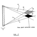
- the constituent parts of the autostereoscopic image in a two window display converge at viewpoint corrected zones.
- Image data (i.e. part of a view) for a first two dimensional (2D) image originating from a first end of the display 5 is constrained to lie in a zone 6, whereas image data for the same 2D image originating from an opposite side of the display is constrained within a zone 8.
- the zones 6 and 8 overlap to provide a first viewpoint corrected zone 12 at which the whole of the first 2D image can be seen.
- image data for a second 2D image is constrained to lie in zones 7 and 10 and these zones overlap to provide a second viewpoint corrected zone 14.
- the observer can perceive an autostereoscopic image when one of the observer's eyes is in the first viewpoint corrected zone 12 and the other of the observer's eyes is in the second viewpoint corrected zone 14. If the observer's eyes are not within the viewpoint corrected zones, the observer does not see a 3D image over the whole of the display.
- the optimum position for viewing the display is in a plane passing through the widest part of each viewpoint corrected zone. It is convenient to regard this plane within a single viewpoint corrected zone as defining a "window".
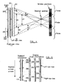
- FIG. 2 schematically illustrates, in plan view, the views seen by an observer who has moved from "windows" formed within the viewpoint corrected zones to a position nearer the display.
- each 2D image is presented along different directions.
- the parts of each 2D image are projected in different directions with respect to position along the display such that the images converge at the viewpoint corrected zones.
- the windows within the viewpoint corrected zones form an alternating pattern showing left views and right views labelled "L" and "R", respectively, in Figure 2. Movement of the observer 16 to the position shown in Figure 2 results in each of the observer's eyes seeing views not intended for it. The views can be calculated by tracing the ray paths back from the boundaries between adjacent windows via each of the observer's eyes to the display 2.
- Solid ray path lines indicate the ray paths for the right eye
- broken ray path lines indicate the ray paths for the left eye.
- the composition of the image seen by each of the eyes is schematically illustrated by the bars 17 and 18 for the right eye "view” and left eye “view”, respectively.
- the dark regions of the bars indicate those parts of the display from which a left view is seen whereas the light regions of the bars indicate those parts of the display from which a right view is seen.
- the left eye now observes a mixture of both left and right views.
- the right eye also observes a mixture of left and right views. If both eyes observe the same view (i.e. left or right) from a given portion of the display, then that portion is seen in 2D only.
- regions of the display such as region 19, result in the left eye receiving a right view and the right eye receiving a left view. This gives rise to a false perception of a 3D image - known as a pseudoscopic image.
- a 500 line lenticular display having a width of 250 mm implies that the size of each lenticule will be 0.5 mm.
- Sixty interocular views would imply a maximum pixel size of 8 micrometers. Such a fine pixel pitch is not presently available over such a large distance.
- Providing such a number of views by means of a beam combiner-type display would require sixty spatial light modulators.
- Embodying such a display as a temporally multiplexed display would require a frame refresh rate of the order of 3 kHz.
- an observer tracking autostereoscopic display comprising at least three image display devices arranged to direct respective images along respective different directions, an observer tracker for determining the position of an observer, and an image controller responsive to the observer tracker for dividing the image displayed by each of the image display devices such that each region of each of the image display devices which emits light towards a left eye of the observer displays left eye view data and each region of each of the image display devices which emits light towards a right eye of the observer displays right eye view data.
- the display has a nominal viewing position or distance at which view slicing is not required to produce a three dimensional image.
- the display has viewpoint correction to the nominal viewing position or distance.
- the at least three different directions are ranges of directions and the ranges are contiguous.
- the image display device may comprise a single spatial light modulator (SLM) or other image display (for example an emissive display such as a cathode ray tube) adjacent a lenticular screen.
- SLM spatial light modulator
- the display devices are spatially multiplexed with a single SLM.
- the display devices may comprise a plurality of spatial light modulators cooperating with respective arrays of light sources in a beam combiner-type display or a single spatial light modulator operated in a time multiplexed manner in conjunction with a time multiplexed light source.
- the display has an output comprising a plurality of lobes, each lobe having at least three image regions. Such an arrangement allows extended lateral movement with respect to the display.
- a display in which a single image display device is controlled so as to produce a display output comprising three or more image regions and in which the position and size of left eye and right eye image data within each of the image regions are varied in response to movement of an observer such that the observer's left eye receives a left view and observer's right eye receives a right view.
- the or each light source may comprise an array of light emitting elements.
- the light emitting elements may be arranged into at least three groups. Each group may have the same inter-element separation and the groups may be interspersed with one another such the elements of each group are arranged in a repeating series.
- a spatial light modulator is illuminated by a segmented back light via a lens array.
- a spatial light modulator is positioned between first and second lenticular screens.
- the spatial light modulator is preferably adjacent the first lenticular screen and the pitch of the first lenticular screen is substantially equal to the pitch of the spatial light modulator.
- the pitch of the second lenticular screen is substantially an integer multiple of the pitch of the first lenticular screen.
- a diffuser may be located intermediate the first and second lenticular screens.
- the first lenticular screen may be illuminated by a multi-element light source having individually controllable elements.
- the diffuser may be positioned such that an image of the light source, modulated by the image data presented to the spatial light modulator, is formed on the diffuser.
- the diffuser is located at an object plane of the second lenticular array.
- the left eye and right eye view data may be sliced and combined by dedicated image processing equipment to form a composite image for presentation by each display device.
- the slicing and combining of the view data may be performed under software control.
- the proportions and positions of the view data used to form each composite image may be stored within a look-up table so as to allow rapid response to movement of an observer. Interpolation of data in the look-up table may be used to enhance the performance of the system.
- an observer tracking autostereoscopic display constituting an embodiment of the present invention is relatively insensitive to small errors in determining the observer's position compared with the very accurate position determination required by some prior art systems.
- a method of tracking an observer with an autostereoscopic display of the type comprising at least three image display devices which direct respective images along respective different directions position of at least one observer, and dividing the image displayed by each of the image display devices such that each region of each of the image display devices which emits light towards a left eye of the observer displays left eye view data and each region of each of the image display devices which emits light towards a right eye of the observer displays right eye view data.
- an autostereoscopic display emits (in plan view) cones of light along predetermined directions. Each cone of light represents part of a view from a given viewing position. Cones relating to the same view but emanating from different parts of the display can be arranged to converge at a viewpoint corrected zone by, for example, making the pitch of a lenticular screen within the display slightly less than the pitch of pixel groups within the display.
- the distance between the display 5 and the widest parts of the viewpoint corrected zones 12 and 14 corresponds to a design viewing distance for the display.
- the positions of the viewpoint corrected zones for the display of Figure 1 are fixed in space with respect to the display and hence such a display has a limited viewing area where the three dimensional effect can be perceived. Lateral or longitudinal movement of an observer will result in loss of the stereoscopic image if either of the observer's eyes moves outside a viewpoint corrected zone or if both eyes move into the same viewpoint corrected zone.
- Figure 3 schematically illustrates in plan view the generation of three views imaged into three lobes using a lenticular array 22 and a spatial light modulator 23.
- the spatial light modulator 23 is arranged to simultaneously display three images in a spatially multiplexed fashion - and hence acts as three different displays.
- the first display is composed of the pixels A
- the second display is composed of the pixels B
- the third display is composed of the pixels C.
- the displays are interleaved so as to form a repeating pixel pattern ABCABC etc.
- the lenticular array 22 comprises a plurality of lenticules whose individual widths are substantially the same as the spatial extent of the three pixels ABC.
- each lenticule is substantially aligned with its respective B pixel (this condition changes slightly for viewpoint corrected displays where the pitch of the lenticules is slightly less that the pattern repeat pitch ABC - but those lenticules towards the centre of the display are substantially aligned with the respective B pixels).
- the images from the pixels are imaged through the lenticules - as shown - to provide three lobes, labelled -1, 0 and +1, each of which comprises three images A', B' and C'.
- viewpoint correction results in the separate images combining within respective windows, labelled 1, 2 and 3 in Figure 4.
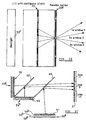
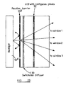
- FIG 4 schematically illustrates an autostereoscopic display comprising a lenticular screen 30 adjacent an image display device 32, such as a liquid crystal device spatial light modulator (arranged like elements 22 and 23 of Figure 3).
- image data is presented to the display device 32 so as to generate a number of output cones, each of which corresponds to a different view. Cones corresponding to the same view converge at a designed position so as to give viewpoint correction within viewpoint corrected zones at which the observer can observe the autostereoscopic effect.
- Each viewpoint corrected zone defines a "window” therein. Each "window" occurs at a predetermined distance from the display device. Movement of the observer towards or away from the display device results in each eye of the observer receiving views that were not intended for that eye.
- the display illustrated is arranged to produce an output having three lobes, labelled -1, 0 and 1, which each comprise three windows.
- Figure 4 also schematically shows the ray paths from the autostereoscopic display to an observer who is located nearer the display than the design position i.e. between the display and the "windows".
- the images seen by the observer can be calculated by tracing back the rays from the window boundaries (i.e. boundaries between adjacent viewpoint corrected zones) through each of the observer's eyes to the display.
- the right eye view will see the image in window 2 of lobe 0 at the right of the display, the image in window 1 of lobe 0 in the middle of the display and the image in window 3 of lobe -1 at the left of the display.
- the observer's left eye will see the image in window 1 of lobe 1 at the right hand end of the display, the image in window 3 of lobe 0 in the middle of the display and the image in window 2 of lobe 0 at the left of the display.
- Each eye of the observer only sees images from distinct non-contiguous regions of each one of the displays when at the position shown in Figure 4. This can be demonstrated by tracing the ray paths back from the boundaries of neighbouring windows through the observer's eyes to the display.
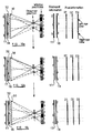
- the first display D1 i.e. the A pixels of Figure 3
- this display generates the images projected to windows 1.
- the left eye only sees light propagating along the cone L1 from the first display, whereas the right eye only sees light propagating along the cone R1 from the first display. Consequently there are regions 200 and 202 of the first display that are not visible to either eye.
- the region 204 ( Figure 5) of the first display D1 visible to the left eye is controlled to display a left eye view (illustrated by black shading)
- the region 206 visible to the right eye is controlled to show a right eye view (illustrated by no shading)
- the first display is controlled to switch between left and right views at the centre of region 200.
- the region 202 is controlled so as to display the right eye view in a portion thereof adjacent the region 206.
- the second display D2 projects an image into the windows 2.
- the right eye only sees light from the second display that propagates within the cone R2 corresponding to region 210 at the second display ( Figure 5).
- the left eye only sees light from the display propagating within the cone L2 corresponding to light emitted from region 212 of the second display.
- a central portion 214 of the second display is not visible to either eye.
- the region 210 is controlled to display a right eye view
- the region 212 is controlled to display a left eye view
- the region 214 is controlled such that the image displayed therein swaps between the left eye and right eye views at approximately the centre of that region, as shown in Figure 5.
- the third display D3 projects an image into the windows 3.
- the left eye only sees light from the third display that propagates within the cone L3 corresponding to light from region 220 of the third display.
- the right eye only sees light propagating within the cone R3 corresponding to light from region 222 of the third display.
- Regions 224 and 226 of the third display are not visible to either eye.
- the third display is controlled such that a left eye view is displayed in regions 220 and 226, a right eye view is displayed in region 222, and region 224 has a transition between left and right views at the centre thereof.
- the left eye only sees left views and the right eye only sees right views.
- the display is not affected by small errors in determining the observer's position and is less likely to be affected by aberrations in the optical system.
- Figure 6 schematically illustrates the ray paths to an observer's eyes when the observer is located further away from the display device than the viewpoint corrected zones. As before, each of the observer's eyes receives views from more than one viewing window.
- Figure 7 which is similar to Figure 5, schematically illustrates the mixture of view data to be presented to each display device in order to recreate the autostereoscopic effect.
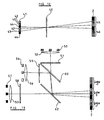
- Figure 8 schematically illustrates the ray paths at the closest viewing position for a three view system in which each lobe at the window position has a lateral extent of twice the interocular distance e.
- the closest position occurs when the angle subtended by the observer's eyes to the display is equal to the angle subtended by two windows.
- the maximum displacement a from the windows towards the display at which an autostereoscopic effect is still observed is given by:
- Figure 9 schematically illustrates the furthest viewing position for a three view system.
- the furthest viewing position is defined when the angle subtended from the display device to the observer's eyes is equal to the angle subtended by one window.
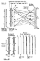
- Figures 10a to 10c are similar to Figures 4 and 5 in that they trace the ray paths back from the window positions through the positions of the observer's eyes to the display device for three positions of an observer which are laterally different but longitudinally the same.
- the figures also display the view information which must be supplied to the or each display device in order to maintain the autostereoscopic effect for the observer at each of his positions.
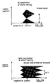
- Figures 11a and 11b compare the spatial extent of the viewing regions at which the autostereoscopic effect can be observed.
- the position Z represents the nominal window position of a display not incorporating an embodiment of the present invention.
- Figure 11a indicates the viewing position for a multilobe display not having observer tracking.
- Figure 11b shows the observer positions for a multilobe display incorporating both longitudinal and lateral observer tracking.
- the ordinate represents the axis of display symmetry (i.e. mid-line of the display) and the shaded regions represent the area in which the autostereoscopic effect can be perceived.
- the minimum viewing distance is 750 mm and the maximum viewing distance is 1,500 mm.
- the display has a total longitudinal freedom of 750 mm.
- An equivalent four view system having tracking allows a minimum viewing distance of 670 mm and a maximum viewing distance of 2,000 mm.
- the interocular distance of an observer is assumed to be 65 mm.
- Embodiments of the present invention make it possible to produce a large field for autostereoscopic viewing.
- the image content displayed to the observer may also be made to vary with respect to observer position so as to give a "look around" facility.
- Methods of tracking the observer's position may include magnetic, infra-red, ultrasonic and video tracking. Tracking systems are known per se and need not be described here in detail.
- Such a display may also compensate for changes in the interocular distance between observers, such as between adults and young children.
- FIG. 12 schematically illustrates an embodiment of the present invention.
- the display comprises a spatial light modulator 40, an illumination source 41 comprising six light emitting elements arranged in pairs 42, 43, and 44, and an imaging element such as a lens or parallax screen (not shown) for forming viewing windows corresponding to the light emitting elements.
- Each pair of light emitting elements has the same inter-element distance as each other pair and the elements are arranged in a common plane.
- the pairs of light emitting elements are illuminated in sequence.
- Video information is supplied to the spatial light modulator in a time multiplexed manner in sequence with the successive illumination of each pair of illuminators.
- Such a display provides two lobes 45 and 46 each having three windows at a nominal viewing position Z.
- FIG. 13 illustrates a further embodiment of the invention.
- a first light source 50 comprises three regularly spaced illuminators and is arranged to illuminate a first spatial light modulator 51 via a lens 52.
- a second light source 54 comprises three regularly spaced illuminators and is arranged to illuminate a second spatial light modulator 55 via a lens 56.
- a third light source 57 comprises three regularly spaced illuminators and is arranged to illuminate a third spatial light modulator 58 via a lens 59.
- Each lens 52, 56 and 59 forms an image of it's respective light source at a nominal viewing position Z.
- a first beam combiner 60 combines the images of the first and second light sources 50 and 54, respectively, following modulation by their respective spatial light modulators.
- This combined image is further combined at a second beam combiner 62 with the image of the third light source 57 following modulation by the third spatial light modulator 58.
- the images are arranged to be laterally offset with respect to one another so as to provide an output of three lobes (labelled -1, 0 and +1) each comprising three windows.
- the windows form a substantially contiguous output at the nominal viewing position Z.
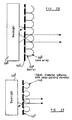
- a back light 70 comprises three groups of light emitting elements. Elements belonging to the first group are labelled 71, elements belonging to the second group are labelled 72 and elements belonging to the third group are labelled 73.
- the light emitting elements are arranged in a repeating sequence of an element from the first group, an element from the second group and an element from the third group.
- Light from the light emitting elements is collected by an array of lenses 75 and is directed towards a nominal observer viewing position Z via a spatial light modulator 76.
- Each group of light emitting elements is illuminated in turn and the spatial light modulator is driven in a time multiplexed manner so as to present a different view to each one of the viewing windows.
- FIG. 15 schematically illustrates a further embodiment of the present invention.
- a spatial light modulator 80 is sandwiched between first and second lenticular arrays 82 and 84.
- the first array 82 is adjacent the spatial light modulator 80 and has a pitch substantially equal to that of the spatial light modulator.
- the second lenticular array 84 has a pitch substantially twice that of the first lenticular array.
- a diffuser 86 is positioned intermediate the spatial light modulator 80 and the second lenticular screen 84.
- First and second light sources 88 and 90 are arranged to illuminate the first lenticular array 82 via a lens 92.
- the diffuser 86 is positioned such that an image of the light sources 88 and 90 is formed thereon following modulation by the spatial light modulator 80.
- the diffuser 86 also lies in an object plane of the second lenticular screen 84.
- the second lenticular screen 84 re-images the diffuser 86 at the nominal viewing position Z.
- the light sources 88 and 90 and the spatial light modulator 80 are driven in a time multiplexed manner.
- a first modulating element 94 of the spatial light modulator 80 forms a modulated image at a position 95 on the diffuser 86 whereas a second element 96 of the spatial light modulator forms an image at a position 97 on the diffuser 86.
- These positions are re-imaged as elements of window views 1 and 4 of each lobe.
- the same modulating elements 94 and 96 form images at positions 98 and 99 respectively on the diffuser 86.
- These images form elements of windows 2 and 3 in each lobe.
- Such an embodiment combines both spatial and temporal multiplexing to provide a multi-lobe four view display.
- Figure 16 schematically illustrates a video multiplexing system for the production of the sliced video images. Although three or four windows are provided, only left and right eye view information is required. Left eye view information is provided via a buffer 100 to left view inputs of first, second and third video switches 102, 104 and 106. Similarly right eye view information is provided via a buffer 108 to right eye inputs of the first, second and third video switches. Each video switcher is responsible for generating the video view to be provided to one of the display devices for generation of a view within one of the windows. Each video switcher may control a respective display device or may be arranged to drive a single display in a multiplexed fashion, for example as shown in Figure 12.
- Each video switcher receives two control inputs from a controller 110 which selects whether the left view or right view should be displayed over a given part of the video output.
- the controller 110 is responsive to a tracking system 112 which determines the position of an observer. From a knowledge of the observer's position and the parameters of the display, the controller selects appropriate views and instructs the video switches to display the relevant parts of the left and right views.
- the controller essentially performs the view analysis illustrated in Figures 4, 6, 8, 9 and 10a to 10c.
- the controller may comprise a look up table which contains data as to which of the left and right views should be selected by each video controller for a given observer position.
- the controller 110 may perform a simple interpolation to improve the degree of control or reduce the number of data points required in the look up table.
- the positions at which the view information is switched can be measured by placing the observer's eyes so that pre-defined slices of images can be seen across the display. For example, referring to Figure 4, display D1 is made red and display D2 is made blue. The observer moves until a red image is seen on the left hand side of the display and a blue image is seen on the right hand side with the right eye. The slice edges are then aligned to reference markers on the edge of the display by movement of the observer's right eye laterally and longitudinally. For this condition to be met, the observer's right eye must be at the above defined position in space, i.e. when the red image is seen on the left hand side of the display and the blue image is seen on the right hand side of the display.
- a set of calibration points can be derived which are used to define the switch positions in the display.
- the maximum extent of the viewing range can be determined so that the backlight is switched off when the observer falls outside an acceptable zone. In this way, it is possible to compensate for aberrations of the optical system.
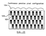
- each lenticule 124 has a pitch substantially equal to that of three columns of pixels.
- the displays are controlled such that they each display a complete left or right view.
- the display shown in Figure 18 is a three view multilobe display such as described with reference to Figures 3, 12, 13 or 14.
- the observer's right eye sees the image in window 1 whereas the observer's left eye sees the images in windows 2 and 3.
- the first display which is viewable in window 1 shows right view data
- the second and third displays which are viewable from windows 2 and 3, respectively, show left view data.
- the second window 2 becomes unobserved and the image displayed therein can be updated to show right view data. Similar analysis for movement between the other positions shows that the image in a window need only be switched between left and right views when the observer is unable to view that window.
- Figure 19 shows a display of the type shown in Figure 4 for tracking two observers.
- the display of Figure 19 differs from that shown in Figure 4 in that the LCD SLM 32 is arranged to provide seven views per lobe imaged at the window positions as shown.
- the SLM 32 thus operates as seven display devices D1 to D7
- the ray paths for the two observers are shown and the views (labelled 1 to 7) which are visible to the right and left eyes of observers "1" and "2" across the display are illustrated by the vertical bars at the left in Figure 19.
- Spatially multiplexed displays which use three or four rather than two windows suffer from reduced resolution. This can be compensated for by spatially multiplexing a fast SLM device, for example a Pi Cell, to generate time multiplexed colour images in each of the views.
- the backlight is then switched between red, green and blue in synchronism with the SLM image.
- a backlight comprising three fluorescent tubes, the fluorescent tubes having a red phosphor, a green phosphor and a blue phosphor, respectively.
- Figure 20 corresponds to Figure 5 and illustrates the pixel information which each of the seven views provides across the SLM 32.
- Each of the views is split between left and right eye views as shown so that the left eyes L1 and L2 and the right eyes R1 and R2 of the observers see only left and right eye views, respectively, across the whole display, thus presenting correct autostereoscopic 3D images to both observers.
- Autostereoscopic displays such as those shown in Figures 12 to 15, may be arranged to track more than one observer.
- the tracking system is required to track each observer independently and the display must be arranged to provide at least three views per observer to permit view slicing so that each observer sees a correct 3D image within an extended viewing region.
- the display shown in Figure 21 differs from that shown in Figure 13 in that the light sources 50, 54, and 57 and the lenses 52, 56, and 59 are replaced by compact illuminators 50a, 54a, and 57a.
- the compact illuminator 50a comprises a lenticular screen 50b behind which is disposed a parallax barrier 50c.
- the parallax barrier 50c comprises a plurality of slits, each of which is aligned with a lenticule of the lenticular screen 50b.
- a Lambertian backlight 50d is disposed behind the parallax barrier 50c.
- the compact illuminators 54a and 57a are identical to the compact illuminator 50a.
- Each lenticule of the lenticular screen 50b images the aligned slit of the parallax barrier 50c to the window of the zero lobe.
- the adjacent lenticules image the same slit to the same windows in the -1 and +1 lobes of the viewing windows. Accordingly, the display shown in Figure 21 operates in the same way as that shown in Figure 13 but can be made more compact.
- Figure 22 shows part of a display which differs from that shown in Figure 4 in that the lenticular screen 30 is replaced by a parallax barrier 30a.
- the barrier 30a comprises a plurality of slits aligned with the pixels of the liquid crystal display 32 as shown in Figure 22.
- a Lambertian backlight 50d is provided behind the liquid crystal display, whose pixels are contiguous with each other.
- each slit directs light along light cones to the first, second, and third windows of the zero lobe from the associated pixels. Further, the slits form +1 and -1 lobe windows such that the windows in each lobe are contiguous with each other and the lobes are contiguous with each other.
- parallax barriers do not suffer from the optical aberrations of lenticular screens.
- the quality of the windows particularly in terms of the width of the boundary of each window, produced at the plane of an observer is controlled by the width of the slits. If the slits are made narrower, the geometric spreading of each window edge is reduced. However, the amount of diffraction occurring at the slit increases with decreasing width of each slit so that it is necessary to choose the width of the slits as a compromise between diffraction and geometric degradation effects.
- Figure 23 illustrates part of a display which differs from that shown in Figure 22 in that the front parallax barrier 30a is replaced by a rear parallax barrier 30b disposed between the liquid crystal display 32 and the backlight 50d.
- a switchable diffuser 130 is provided between the barrier 30b and the display 32.
- the surface of the barrier 30b facing the backlight 50d is made reflective so that light which does not pass through the slits of the barrier 30b is reflected back to the backlight 50d for reuse. This improves the brightness of the displayed image.
- the display may be used for two dimensional (2D) operation by switching the switchable diffuser 130 so as to diffuse light from the slits of the barrier 30b.
- the liquid crystal display 32 is then illuminated by a Lambertian source and 2D images are visible throughout a wide viewing range.
- the rear parallax barrier 30b may be made as an array of transparent slits in an opaque mask.
- the barrier may be made by imaging a defined size light source through a lenticular screen on to a diffuser.
- Figure 24 illustrates diagrammatically an alternative technique for producing three or more contiguous windows by means of a hologram 131 comprising a plurality of holographic elements 132 associated with respective pixels of the spatial light modulator of the display and tuned for the appropriate colour filters of the pixels.
- holographic elements 132 are equivalent in operation to a lenticular screen or parallax barrier and, when appropriately illuminated for instance by a collimated white light reconstructing beam 133, each holographic element 132 produces a defined window for the associated colour.
- Each holographic element may be recorded so as to define several lobes as shown in Figure 24.
- the holographic elements 132 are arranged in groups so that the light from each group of pixels is imaged to one of the three or more groups of windows as shown in Figure 25.
- the intensity of the light is controlled by the pixel switching properties and the directionality by the hologram 131.
- the hologram 131 may be disposed inside a spatial light modulator 135 together with a liquid crystal layer 136 and a colour filter 137.
- the hologram is disposed substantially at the plane of the liquid crystal device forming the SLM135, for instance by controlling the pattern of a black mask inside the pixel aperture.
- the hologram at each pixel can be tuned so as to direct light for the particular colour associated with the colour filter for that pixel to the appropriate window. This is indicated in Figure 26 by abbreviations such that "W” refers to a window and "R", “G”, and “B” refer to red, green, and blue light, respectively.
- W refers to a window
- R red, green, and blue light
- a light source for the display may contain three narrow spectral peaks which may be obtained by the appropriate choice of phosphors used in fluorescent tubes which, in combination with the colour filter and pixels, results in relatively small spectral spreading of the light from the holographic elements.
- Figure 27 shows an alternative arrangement in which the hologram 131 is disposed on the outer surface of the SLM 135.
- this arrangement by using collimated illumination, it is possible to make use of holograms formed in a photopolymer or dichromated gelatine or in the form of etched surface relief or embossed holograms.
- gratings may be created in the SLM.
- the holograms 131 may be computer generated or may be recorded by interfering light from an illuminated window with a reference beam. For instance, a mask may be used to expose a recording plate at the first window of each lobe through a red colour filter together with a red reference beam. This may then be repeated for green and blue light. The process then may be repeated for each window and each corresponding holographic element.
- Figure 28 illustrates a compact collimated white backlight which may be used for illuminating the holograms 131.
- the backlight shown in Figure 28 differs from that shown in Figure 21 in that barriers 50e are arranged between elements of the lens array 50b and the lens array 50b is arranged to produce collimated light.
- the rear surface of the barrier 50c is made reflective so as to return unused light to the backlight illuminator 50d for reuse.
- Figure 29 shows a collimated backlight which differs from that shown in Figure 28 in that the lens array 50b and the barrier 50e are replaced by small glass spheres 140 having a large packing density.
- Figure 30 shows the boundaries between different view information for the left and right eye images, these boundaries being curved instead of being vertical lines.
- the display may be configured so that different parts have different image information so that the information displayed across the display is appropriate for maintaining an autostereoscopic image at the observer.
- Such a display is more robust and offers quicker response compared to a display incorporating moving parts.
- Such a display is also relatively insensitive to errors in the tracking of the observer.
- a non-mechanical, electronic, lateral and longitudinal tracking method and a mechanical tracking method for example, translating a parallax element, for example a parallax barrier or a lenticular screen with respect to an SLM or rotating a sandwich comprising at least a parallax element and an SLM in a flat panel type display
- a mechanical tracking method for example, translating a parallax element, for example a parallax barrier or a lenticular screen with respect to an SLM or rotating a sandwich comprising at least a parallax element and an SLM in a flat panel type display
- a relatively slow mechanical system can either translate the parallax barrier or lenticular screen with respect to the SLM, or rotate the sandwich.
- the non-mechanical tracking method working in conjunction with the mechanical tracking method allows the observer to maintain an autostereoscopic image throughout with extended longitudinal viewing freedom which is not possible if only the mechanical method is used.
Description
- The present invention relates to an observer tracking autostereoscopic display and to a method of tracking an observer.
- It is desirable to provide an autostereoscopic display in which the three dimensional effect is perceived for a wide range of observer positions.
- Methods of producing autostereoscopic images rely on presenting different views to the left and right eyes of an observer. This can be achieved by dividing the views for the left and right eyes into a series of interleaved vertical stripes. A lenticular screen is then placed adjacent the composite image such that each lenticule covers one view stripe of the left eye image and one view stripe of the right eye image.
- Electrically controlled displays may also split the left and right eye images into vertical stripes and replay the images along different directions using a lenticular screen. In another arrangement, two screens may display the images for the left and right eyes, respectively, and the images therefrom can be combined by a beamcombiner. Such a display is disclosed in EP-A-0602934. A single spatial light modulator can also be driven in a time multiplexed manner to reproduce the left and right eye images, the position of a source of illumination being varied in a time multiplexed manner so as to project the different images in different directions. The displays require the viewer to be positioned in a defined viewing region to observe the 3D effect.
- K. Akiyama and N. Tetsutani, "3-Dimensional Visual Communication", ITEC'91: 1991 ITE Annual Convention, disclose an observer tracking autostereoscopic display in which a liquid crystal display (LCD) is positioned in close proximity to a lenticular sheet such that each lenticule is in front of two columns of pixels of the LCD. Such an arrangement angularly multiplexes the light emitted from the columns of pixels in the display. The display is driven so as to provide interlaced left and right images for projection to the left and right eyes of an observer. Movement of the observer makes it possible for the observer's left eye to be in a position where it receives the image intended for the observer's right eye and vice versa. A position detector monitors the position of the observer's head and is arranged to swap the left and right images over in response to movement of the observer such that the correct image is presented to the correct eye.
- Such a system will allow limited freedom of movement of an observer laterally with respect to the display.
- EP-A-0 354 851 discloses both a "two window" and a "four window" display. As shown in Figure 1 of the accompanying drawings, the constituent parts of the autostereoscopic image in a two window display converge at viewpoint corrected zones. Image data (i.e. part of a view) for a first two dimensional (2D) image originating from a first end of the
display 5 is constrained to lie in azone 6, whereas image data for the same 2D image originating from an opposite side of the display is constrained within a zone 8. Thezones 6 and 8 overlap to provide a first viewpoint correctedzone 12 at which the whole of the first 2D image can be seen. Similarly, image data for a second 2D image is constrained to lie inzones zone 14. The observer can perceive an autostereoscopic image when one of the observer's eyes is in the first viewpoint correctedzone 12 and the other of the observer's eyes is in the second viewpoint correctedzone 14. If the observer's eyes are not within the viewpoint corrected zones, the observer does not see a 3D image over the whole of the display. The optimum position for viewing the display is in a plane passing through the widest part of each viewpoint corrected zone. It is convenient to regard this plane within a single viewpoint corrected zone as defining a "window". - Such a two view display provides only very limited freedom of movement for an observer. Figure 2 schematically illustrates, in plan view, the views seen by an observer who has moved from "windows" formed within the viewpoint corrected zones to a position nearer the display.
- As noted hereinabove, parts of each 2D image are presented along different directions. In a viewpoint corrected display, the parts of each 2D image are projected in different directions with respect to position along the display such that the images converge at the viewpoint corrected zones. In a two view multilobe system, the windows within the viewpoint corrected zones form an alternating pattern showing left views and right views labelled "L" and "R", respectively, in Figure 2. Movement of the
observer 16 to the position shown in Figure 2 results in each of the observer's eyes seeing views not intended for it. The views can be calculated by tracing the ray paths back from the boundaries between adjacent windows via each of the observer's eyes to thedisplay 2. Solid ray path lines indicate the ray paths for the right eye, whereas broken ray path lines indicate the ray paths for the left eye. The composition of the image seen by each of the eyes is schematically illustrated by thebars region 19, result in the left eye receiving a right view and the right eye receiving a left view. This gives rise to a false perception of a 3D image - known as a pseudoscopic image. - As is clearly demonstrated, the autostereoscopic effect across the entirety of the display has been lost.
- It is further desirable to provide a "look around" display in which the view presented to the observer is a function of the observer's position. It has been estimated that sixty views per interocular separation may be required in order to achieve an artifact free representation of a 3D image. A 500 line lenticular display having a width of 250 mm implies that the size of each lenticule will be 0.5 mm. Sixty interocular views would imply a maximum pixel size of 8 micrometers. Such a fine pixel pitch is not presently available over such a large distance. Providing such a number of views by means of a beam combiner-type display would require sixty spatial light modulators. Embodying such a display as a temporally multiplexed display would require a frame refresh rate of the order of 3 kHz.
- The number of views required to provide a "look around" 3D image can be greatly reduced by using an observer tracking display, since only the views directed towards the observer's eyes need be displayed. Arrangements in which the positions of the "windows" are movable so as to move with movement of an observer are disclosed in
EP 0 576 106 andEP 0 656 555. - According to a first aspect of the present invention, there is provided an observer tracking autostereoscopic display, comprising at least three image display devices arranged to direct respective images along respective different directions, an observer tracker for determining the position of an observer, and an image controller responsive to the observer tracker for dividing the image displayed by each of the image display devices such that each region of each of the image display devices which emits light towards a left eye of the observer displays left eye view data and each region of each of the image display devices which emits light towards a right eye of the observer displays right eye view data.
- It is thus possible to provide an autostereoscopic display in which the observer is not constrained within a relatively small autostereoscopic viewing zone at a fixed distance from the display, but in which the observer is free to move within a greatly increased viewing zone. "View slicing" of the left and right views such that a portion of each is displayed by each display device enables the observer to move longitudinally with respect to the display.
- Preferably the display has a nominal viewing position or distance at which view slicing is not required to produce a three dimensional image. Advantageously the display has viewpoint correction to the nominal viewing position or distance.
- Preferably the at least three different directions are ranges of directions and the ranges are contiguous.
- The image display device may comprise a single spatial light modulator (SLM) or other image display (for example an emissive display such as a cathode ray tube) adjacent a lenticular screen. Thus the display devices are spatially multiplexed with a single SLM. Alternatively, the display devices may comprise a plurality of spatial light modulators cooperating with respective arrays of light sources in a beam combiner-type display or a single spatial light modulator operated in a time multiplexed manner in conjunction with a time multiplexed light source.
- Preferably the display has an output comprising a plurality of lobes, each lobe having at least three image regions. Such an arrangement allows extended lateral movement with respect to the display.
- It is thus possible to provide a display in which a single image display device is controlled so as to produce a display output comprising three or more image regions and in which the position and size of left eye and right eye image data within each of the image regions are varied in response to movement of an observer such that the observer's left eye receives a left view and observer's right eye receives a right view.
- The or each light source may comprise an array of light emitting elements. The light emitting elements may be arranged into at least three groups. Each group may have the same inter-element separation and the groups may be interspersed with one another such the elements of each group are arranged in a repeating series.
- In an embodiment of the present invention, a spatial light modulator is illuminated by a segmented back light via a lens array.
- In a further embodiment of the present invention a spatial light modulator is positioned between first and second lenticular screens. The spatial light modulator is preferably adjacent the first lenticular screen and the pitch of the first lenticular screen is substantially equal to the pitch of the spatial light modulator. Advantageously the pitch of the second lenticular screen is substantially an integer multiple of the pitch of the first lenticular screen. A diffuser may be located intermediate the first and second lenticular screens. The first lenticular screen may be illuminated by a multi-element light source having individually controllable elements. The diffuser may be positioned such that an image of the light source, modulated by the image data presented to the spatial light modulator, is formed on the diffuser. Preferably the diffuser is located at an object plane of the second lenticular array.
- The left eye and right eye view data may be sliced and combined by dedicated image processing equipment to form a composite image for presentation by each display device. Alternatively the slicing and combining of the view data may be performed under software control. The proportions and positions of the view data used to form each composite image may be stored within a look-up table so as to allow rapid response to movement of an observer. Interpolation of data in the look-up table may be used to enhance the performance of the system.
- Furthermore, an observer tracking autostereoscopic display constituting an embodiment of the present invention is relatively insensitive to small errors in determining the observer's position compared with the very accurate position determination required by some prior art systems.
- According to a second aspect of the present invention there is provided a method of tracking an observer with an autostereoscopic display of the type comprising at least three image display devices which direct respective images along respective different directions position of at least one observer, and dividing the image displayed by each of the image display devices such that each region of each of the image display devices which emits light towards a left eye of the observer displays left eye view data and each region of each of the image display devices which emits light towards a right eye of the observer displays right eye view data.
- The present invention will further be described, by way of example, with reference to the accompanying drawings, in which:-
- Figure 1 is a diagram schematically illustrating the positions of viewpoint corrected zones for a two window display;
- Figure 2 schematically shows the limited freedom of movement for an observer viewing a two view multilobe autostereoscopic display;
- Figure 3 schematically shows the generation of a three view, three lobe display by a single spatial light modulator and a lenticular array;
- Figure 4 is a schematic illustration showing the ray paths to an observer's eyes when the observer is positioned between a three window, multilobe autostereoscopic display and the design window positions for that display;
- Figure 5 is a schematic illustration of the image data which must be presented to the or each display device in order to maintain the autostereoscopic effect for the observer at the position shown in Figure 4;
- Figure 6 is a schematic illustration showing the ray paths from the autostereoscopic display to the eyes of an observer who is located beyond the design position of the viewing windows;
- Figure 7 is a schematic diagram showing the image data which must be presented to the or each image display device in order to maintain an autostereoscopic effect for the observer shown at the position in Figure 6;
- Figure 8 is a diagram showing the ray paths from the display to an observer at the closest viewing position at which the autostereoscopic effect is visible;
- Figure 9 is a schematic diagram showing the ray paths from the autostereoscopic display to an observer at the furthest viewing position at which the autostereoscopic effect is visible;
- Figures 10a, 10b and 10c are schematic illustrations of the ray paths and 2D image data required to achieve an autostereoscopic effect at the observer positioned closer to the display than the design window distance and moving laterally;
- Figures 11a and 11b schematically illustrate the range of positions with respect to the display in which an observer will perceive the autostereoscopic effect;
- Figure 12 is a schematic illustration of a time multiplexed display constituting an embodiment of the present invention;
- Figure 13 is a schematic illustration of a three view beam combiner display constituting an embodiment of the present invention;
- Figure 14 is a schematic diagram of a time multiplexed display with compact illumination constituting an embodiment of the present invention;
- Figure 15 is a schematic diagram illustrating a four view display constituting a further embodiment of the present invention;
- Figure 16 schematically illustrates a multiplexing system for the production of sliced video images;
- Figure 17 schematically illustrates a pixel arrangement within an LCD screen for allowing the formation of contiguous image zones in lenticular displays;
- Figure 18 schematically illustrates the operation of an embodiment of the present invention for an observer at the nominal viewing distance;
- Figure 19 is a schematic illustration showing the ray paths to two observers' eyes when the observers are positioned between a seven window multilobe autostereoscopic display and the design window positions for that display;
- Figure 20 is a schematic illustration of the image data which must be presented to the or each display device in order to maintain the autostereoscopic effect for the observers at the positions shown in Figure 19.
- Figure 21 is a schematic illustration of another three view beam combiner display constituting an embodiment of the invention;
- Figure 22 is a schematic sectional view of part of a display using a front parallax barrier;
- Figure 23 is a schematic sectional view of part of a display using a rear parallax barrier;
- Figures 24 and 25 illustrate diagrammatically the use of holograms to form viewing windows;
- Figure 26 is a schematic sectional view of part of a display using an internal hologram;
- Figure 27 is a schematic sectional view of part of a display using an external hologram;
- Figures 28 and 29 are schematic sectional views of compact backlight for illuminating holograms; and
- Figure 30 illustrates the use of curves view slice edges for compensating for aberrations.
-
- As shown in Figure 1, an autostereoscopic display emits (in plan view) cones of light along predetermined directions. Each cone of light represents part of a view from a given viewing position. Cones relating to the same view but emanating from different parts of the display can be arranged to converge at a viewpoint corrected zone by, for example, making the pitch of a lenticular screen within the display slightly less than the pitch of pixel groups within the display. The distance between the
display 5 and the widest parts of the viewpoint correctedzones - Figure 3 schematically illustrates in plan view the generation of three views imaged into three lobes using a
lenticular array 22 and a spatiallight modulator 23. The spatiallight modulator 23 is arranged to simultaneously display three images in a spatially multiplexed fashion - and hence acts as three different displays. The first display is composed of the pixels A, the second display is composed of the pixels B, and the third display is composed of the pixels C. The displays are interleaved so as to form a repeating pixel pattern ABCABC etc. Thelenticular array 22 comprises a plurality of lenticules whose individual widths are substantially the same as the spatial extent of the three pixels ABC. Furthermore the centre of each lenticule is substantially aligned with its respective B pixel (this condition changes slightly for viewpoint corrected displays where the pitch of the lenticules is slightly less that the pattern repeat pitch ABC - but those lenticules towards the centre of the display are substantially aligned with the respective B pixels). The images from the pixels are imaged through the lenticules - as shown - to provide three lobes, labelled -1, 0 and +1, each of which comprises three images A', B' and C'. As described hereinabove with reference to Figure 1, viewpoint correction results in the separate images combining within respective windows, labelled 1, 2 and 3 in Figure 4. - Figure 4 schematically illustrates an autostereoscopic display comprising a
lenticular screen 30 adjacent animage display device 32, such as a liquid crystal device spatial light modulator (arranged likeelements display device 32 so as to generate a number of output cones, each of which corresponds to a different view. Cones corresponding to the same view converge at a designed position so as to give viewpoint correction within viewpoint corrected zones at which the observer can observe the autostereoscopic effect. Each viewpoint corrected zone defines a "window" therein. Each "window" occurs at a predetermined distance from the display device. Movement of the observer towards or away from the display device results in each eye of the observer receiving views that were not intended for that eye. The display illustrated is arranged to produce an output having three lobes, labelled
-1, 0 and 1, which each comprise three windows. - Figure 4 also schematically shows the ray paths from the autostereoscopic display to an observer who is located nearer the display than the design position i.e. between the display and the "windows". The images seen by the observer can be calculated by tracing back the rays from the window boundaries (i.e. boundaries between adjacent viewpoint corrected zones) through each of the observer's eyes to the display. As shown, the right eye view will see the image in
window 2 oflobe 0 at the right of the display, the image inwindow 1 oflobe 0 in the middle of the display and the image inwindow 3 of lobe -1 at the left of the display. The observer's left eye will see the image inwindow 1 oflobe 1 at the right hand end of the display, the image inwindow 3 oflobe 0 in the middle of the display and the image inwindow 2 oflobe 0 at the left of the display. - From consideration of the optical paths shown in Figure 4, it is apparent that it is possible to present parts of two or more views to each display so as to compensate for movement of the observer out of the plane of the windows.
- The observer does not see a view of the entirety of each one of the displays, i.e. pixel groups A, B and C of Figure 3, when he moves away from the nominal viewing distance.
- Each eye of the observer only sees images from distinct non-contiguous regions of each one of the displays when at the position shown in Figure 4. This can be demonstrated by tracing the ray paths back from the boundaries of neighbouring windows through the observer's eyes to the display.
- Considering the first display D1 (i.e. the A pixels of Figure 3), this display generates the images projected to
windows 1. The left eye only sees light propagating along the cone L1 from the first display, whereas the right eye only sees light propagating along the cone R1 from the first display. Consequently there areregions region 200. Theregion 202 is controlled so as to display the right eye view in a portion thereof adjacent the region 206. - Similarly the second display D2 (i.e. the B pixels) projects an image into the
windows 2. The right eye only sees light from the second display that propagates within the cone R2 corresponding toregion 210 at the second display (Figure 5). The left eye only sees light from the display propagating within the cone L2 corresponding to light emitted fromregion 212 of the second display. Acentral portion 214 of the second display is not visible to either eye. Theregion 210 is controlled to display a right eye view, theregion 212 is controlled to display a left eye view and theregion 214 is controlled such that the image displayed therein swaps between the left eye and right eye views at approximately the centre of that region, as shown in Figure 5. - The third display D3 (i.e. the C pixels) projects an image into the
windows 3. The left eye only sees light from the third display that propagates within the cone L3 corresponding to light fromregion 220 of the third display. The right eye only sees light propagating within the cone R3 corresponding to light fromregion 222 of the third display.Regions 224 and 226 of the third display are not visible to either eye. The third display is controlled such that a left eye view is displayed inregions 220 and 226, a right eye view is displayed inregion 222, andregion 224 has a transition between left and right views at the centre thereof. - Thus, the left eye only sees left views and the right eye only sees right views.
- Furthermore by controlling the
regions - A similar analysis can be performed for other positions of the observer and for other display types, such as those shown in Figures 12 to 15.
- Figure 6 schematically illustrates the ray paths to an observer's eyes when the observer is located further away from the display device than the viewpoint corrected zones. As before, each of the observer's eyes receives views from more than one viewing window.
- Figure 7, which is similar to Figure 5, schematically illustrates the mixture of view data to be presented to each display device in order to recreate the autostereoscopic effect.
- Figure 8 schematically illustrates the ray paths at the closest viewing position for a three view system in which each lobe at the window position has a lateral extent of twice the interocular distance e. As shown, the closest position occurs when the angle subtended by the observer's eyes to the display is equal to the angle subtended by two windows. In general, for a display having N windows at a distance z from the display, the maximum displacement a from the windows towards the display at which an autostereoscopic effect is still observed is given by:

- Figure 9 schematically illustrates the furthest viewing position for a three view system. The furthest viewing position is defined when the angle subtended from the display device to the observer's eyes is equal to the angle subtended by one window. In general, for an N window display, the maximum distance b beyond the window positions is given by:
- Lateral movement of the observer away from the axis of the display results in a small change in the maximum and minimum viewing distances due to the finite size of the display and aberrations within the optical components.
- It is thus possible to longitudinally extend the range of viewing positions at which the autostereoscopic effect can be observed by updating the information displayed by each display device in accordance with the position of the observer.
- Lateral and longitudinal tracking may be performed simultaneously by the same display, as schematically illustrated in Figures 10a to 10c. Figures 10a to 10c are similar to Figures 4 and 5 in that they trace the ray paths back from the window positions through the positions of the observer's eyes to the display device for three positions of an observer which are laterally different but longitudinally the same. The figures also display the view information which must be supplied to the or each display device in order to maintain the autostereoscopic effect for the observer at each of his positions.
- Figures 11a and 11b compare the spatial extent of the viewing regions at which the autostereoscopic effect can be observed. In each figure the position Z represents the nominal window position of a display not incorporating an embodiment of the present invention. Figure 11a indicates the viewing position for a multilobe display not having observer tracking. Figure 11b shows the observer positions for a multilobe display incorporating both longitudinal and lateral observer tracking. In each case, the ordinate represents the axis of display symmetry (i.e. mid-line of the display) and the shaded regions represent the area in which the autostereoscopic effect can be perceived.
- For a three view display having a display size of 200 mm with a nominal observer distance of 1,000 mm, the minimum viewing distance is 750 mm and the maximum viewing distance is 1,500 mm. Thus the display has a total longitudinal freedom of 750 mm.
- An equivalent four view system having tracking allows a minimum viewing distance of 670 mm and a maximum viewing distance of 2,000 mm. In each of the above examples, the interocular distance of an observer is assumed to be 65 mm.
- The use of more views enables a larger longitudinal observer movement to be accommodated and also a wider range of interocular separations. Increased viewer freedom is generally obtained at the expense of lower display resolution and/or greater complexity.
- Embodiments of the present invention make it possible to produce a large field for autostereoscopic viewing. The image content displayed to the observer may also be made to vary with respect to observer position so as to give a "look around" facility.
- Methods of tracking the observer's position may include magnetic, infra-red, ultrasonic and video tracking. Tracking systems are known per se and need not be described here in detail.
- Such a display may also compensate for changes in the interocular distance between observers, such as between adults and young children.
- Figure 12 schematically illustrates an embodiment of the present invention. The display comprises a spatial
light modulator 40, an illumination source 41 comprising six light emitting elements arranged inpairs lobes 45 and 46 each having three windows at a nominal viewing position Z. - Figure 13 illustrates a further embodiment of the invention. A
first light source 50 comprises three regularly spaced illuminators and is arranged to illuminate a first spatiallight modulator 51 via alens 52. Similarly, a secondlight source 54 comprises three regularly spaced illuminators and is arranged to illuminate a second spatiallight modulator 55 via alens 56. Similarly, a thirdlight source 57 comprises three regularly spaced illuminators and is arranged to illuminate a third spatiallight modulator 58 via alens 59. Eachlens first beam combiner 60 combines the images of the first and secondlight sources second beam combiner 62 with the image of the thirdlight source 57 following modulation by the third spatiallight modulator 58. The images are arranged to be laterally offset with respect to one another so as to provide an output of three lobes (labelled -1, 0 and +1) each comprising three windows. The windows form a substantially contiguous output at the nominal viewing position Z. - Figure 14 schematically illustrates a further embodiment of the present invention. A
back light 70 comprises three groups of light emitting elements. Elements belonging to the first group are labelled 71, elements belonging to the second group are labelled 72 and elements belonging to the third group are labelled 73. The light emitting elements are arranged in a repeating sequence of an element from the first group, an element from the second group and an element from the third group. Light from the light emitting elements is collected by an array oflenses 75 and is directed towards a nominal observer viewing position Z via a spatiallight modulator 76. Each group of light emitting elements is illuminated in turn and the spatial light modulator is driven in a time multiplexed manner so as to present a different view to each one of the viewing windows. - Figure 15 schematically illustrates a further embodiment of the present invention. A spatial
light modulator 80 is sandwiched between first and secondlenticular arrays first array 82 is adjacent the spatiallight modulator 80 and has a pitch substantially equal to that of the spatial light modulator. The secondlenticular array 84 has a pitch substantially twice that of the first lenticular array. Adiffuser 86 is positioned intermediate the spatiallight modulator 80 and the secondlenticular screen 84. First and secondlight sources lenticular array 82 via alens 92. Thediffuser 86 is positioned such that an image of thelight sources light modulator 80. Thediffuser 86 also lies in an object plane of the secondlenticular screen 84. The secondlenticular screen 84 re-images thediffuser 86 at the nominal viewing position Z. - The
light sources light modulator 80 are driven in a time multiplexed manner. When thefirst light source 88 is illuminated, afirst modulating element 94 of the spatiallight modulator 80 forms a modulated image at aposition 95 on thediffuser 86 whereas asecond element 96 of the spatial light modulator forms an image at aposition 97 on thediffuser 86. These positions are re-imaged as elements ofwindow views first illuminator 88 is extinguished and thesecond illuminator 90 is illuminated, thesame modulating elements positions diffuser 86. These images form elements ofwindows - Figure 16 schematically illustrates a video multiplexing system for the production of the sliced video images. Although three or four windows are provided, only left and right eye view information is required. Left eye view information is provided via a
buffer 100 to left view inputs of first, second and third video switches 102, 104 and 106. Similarly right eye view information is provided via abuffer 108 to right eye inputs of the first, second and third video switches. Each video switcher is responsible for generating the video view to be provided to one of the display devices for generation of a view within one of the windows. Each video switcher may control a respective display device or may be arranged to drive a single display in a multiplexed fashion, for example as shown in Figure 12. Each video switcher receives two control inputs from a controller 110 which selects whether the left view or right view should be displayed over a given part of the video output. The controller 110 is responsive to atracking system 112 which determines the position of an observer. From a knowledge of the observer's position and the parameters of the display, the controller selects appropriate views and instructs the video switches to display the relevant parts of the left and right views. - The controller essentially performs the view analysis illustrated in Figures 4, 6, 8, 9 and 10a to 10c. The controller may comprise a look up table which contains data as to which of the left and right views should be selected by each video controller for a given observer position. The controller 110 may perform a simple interpolation to improve the degree of control or reduce the number of data points required in the look up table.
- The positions at which the view information is switched can be measured by placing the observer's eyes so that pre-defined slices of images can be seen across the display. For example, referring to Figure 4, display D1 is made red and display D2 is made blue.
The observer moves until a red image is seen on the left hand side of the display and a blue image is seen on the right hand side with the right eye. The slice edges are then aligned to reference markers on the edge of the display by movement of the observer's right eye laterally and longitudinally. For this condition to be met, the observer's right eye must be at the above defined position in space, i.e. when the red image is seen on the left hand side of the display and the blue image is seen on the right hand side of the display. In this way, a set of calibration points can be derived which are used to define the switch positions in the display. In particular, the maximum extent of the viewing range can be determined so that the backlight is switched off when the observer falls outside an acceptable zone. In this way, it is possible to compensate for aberrations of the optical system. - For a display using a lenticular screen with a thin film transistor twisted nematic liquid crystal display, such as the display illustrated in Figure 3, it is desirable that masked areas between individual pixels of the spatial light modulator should not be imaged as black bands. This problem can be overcome by using a pixel configuration of the type shown in Figure 17. The arrangement of pixels as shown in Figure 17 enables lateral gaps between the
pixel group 120 and thepixel group 122 to be eliminated while still providing space for control lines within the display. - For a three window display, each lenticule 124 has a pitch substantially equal to that of three columns of pixels.
- When the observer is positioned in the plane of the windows, as shown in Figure 18, the displays are controlled such that they each display a complete left or right view. The display shown in Figure 18 is a three view multilobe display such as described with reference to Figures 3, 12, 13 or 14. When the observer is at position A in Figure 18, the observer's right eye sees the image in
window 1 whereas the observer's left eye sees the images inwindows window 1 shows right view data whereas the second and third displays which are viewable fromwindows second window 2 becomes unobserved and the image displayed therein can be updated to show right view data. Similar analysis for movement between the other positions shows that the image in a window need only be switched between left and right views when the observer is unable to view that window. - It is possible to provide autostereoscopic displays which are capable of tracking more than one observer. For instance, Figure 19 shows a display of the type shown in Figure 4 for tracking two observers. The display of Figure 19 differs from that shown in Figure 4 in that the
LCD SLM 32 is arranged to provide seven views per lobe imaged at the window positions as shown. TheSLM 32 thus operates as seven display devices D1 to D7 The ray paths for the two observers are shown and the views (labelled 1 to 7) which are visible to the right and left eyes of observers "1" and "2" across the display are illustrated by the vertical bars at the left in Figure 19. - Spatially multiplexed displays which use three or four rather than two windows suffer from reduced resolution. This can be compensated for by spatially multiplexing a fast SLM device, for example a Pi Cell, to generate time multiplexed colour images in each of the views. The backlight is then switched between red, green and blue in synchronism with the SLM image. For a flat display, this may be achieved by using a backlight comprising three fluorescent tubes, the fluorescent tubes having a red phosphor, a green phosphor and a blue phosphor, respectively.
- In this way, the benefits of increased viewer freedom obtained by electronic tracking methods may be maintained with an extended viewing freedom generated by view slicing together with a display resolution which is similar to a conventional 2D display.
- Figure 20 corresponds to Figure 5 and illustrates the pixel information which each of the seven views provides across the
SLM 32. Each of the views is split between left and right eye views as shown so that the left eyes L1 and L2 and the right eyes R1 and R2 of the observers see only left and right eye views, respectively, across the whole display, thus presenting correct autostereoscopic 3D images to both observers. - Other types of autostereoscopic displays, such as those shown in Figures 12 to 15, may be arranged to track more than one observer. The tracking system is required to track each observer independently and the display must be arranged to provide at least three views per observer to permit view slicing so that each observer sees a correct 3D image within an extended viewing region.
- The above discussions have assumed have the optical elements were perfect. Aberrations within optical elements can distort the size and position of the windows. However, these effects can be compensated for from knowledge of the actual properties of the optical system - either by calculation or from mapping the window positions.
- The display shown in Figure 21 differs from that shown in Figure 13 in that the
light sources lenses lenticular screen 50b behind which is disposed a parallax barrier 50c. The parallax barrier 50c comprises a plurality of slits, each of which is aligned with a lenticule of thelenticular screen 50b. ALambertian backlight 50d is disposed behind the parallax barrier 50c. The compact illuminators 54a and 57a are identical to the compact illuminator 50a. - Each lenticule of the
lenticular screen 50b images the aligned slit of the parallax barrier 50c to the window of the zero lobe. In addition, the adjacent lenticules image the same slit to the same windows in the -1 and +1 lobes of the viewing windows. Accordingly, the display shown in Figure 21 operates in the same way as that shown in Figure 13 but can be made more compact. - Figure 22 shows part of a display which differs from that shown in Figure 4 in that the
lenticular screen 30 is replaced by a parallax barrier 30a. The barrier 30a comprises a plurality of slits aligned with the pixels of theliquid crystal display 32 as shown in Figure 22. ALambertian backlight 50d is provided behind the liquid crystal display, whose pixels are contiguous with each other. - As shown in Figure 22, each slit directs light along light cones to the first, second, and third windows of the zero lobe from the associated pixels. Further, the slits form +1 and -1 lobe windows such that the windows in each lobe are contiguous with each other and the lobes are contiguous with each other.
- Although displays of the type shown in Figure 22 having a "front" parallax barrier 30a produce a darker image, for a given level of illumination, compared with displays using lenticular screens, parallax barriers do not suffer from the optical aberrations of lenticular screens. In a front parallax barrier display, the quality of the windows, particularly in terms of the width of the boundary of each window, produced at the plane of an observer is controlled by the width of the slits. If the slits are made narrower, the geometric spreading of each window edge is reduced. However, the amount of diffraction occurring at the slit increases with decreasing width of each slit so that it is necessary to choose the width of the slits as a compromise between diffraction and geometric degradation effects.
- Figure 23 illustrates part of a display which differs from that shown in Figure 22 in that the front parallax barrier 30a is replaced by a rear parallax barrier 30b disposed between the
liquid crystal display 32 and thebacklight 50d. Aswitchable diffuser 130 is provided between the barrier 30b and thedisplay 32. The surface of the barrier 30b facing thebacklight 50d is made reflective so that light which does not pass through the slits of the barrier 30b is reflected back to thebacklight 50d for reuse. This improves the brightness of the displayed image. - The use of a rear parallax barrier 30b results in the geometric spreading of each window edge being controlled by the width of the slits of the parallax barrier whereas the diffraction spreading of the edges is controlled by the width of the pixels of the
display 32. It is therefore possible to improve the quality of the window imaging compared with the display shown in Figure 22 using the front parallax barrier. - The display may be used for two dimensional (2D) operation by switching the
switchable diffuser 130 so as to diffuse light from the slits of the barrier 30b. Theliquid crystal display 32 is then illuminated by a Lambertian source and 2D images are visible throughout a wide viewing range. - The rear parallax barrier 30b may be made as an array of transparent slits in an opaque mask. Alternatively, the barrier may be made by imaging a defined size light source through a lenticular screen on to a diffuser.
- Figure 24 illustrates diagrammatically an alternative technique for producing three or more contiguous windows by means of a
hologram 131 comprising a plurality ofholographic elements 132 associated with respective pixels of the spatial light modulator of the display and tuned for the appropriate colour filters of the pixels. Suchholographic elements 132 are equivalent in operation to a lenticular screen or parallax barrier and, when appropriately illuminated for instance by a collimated whitelight reconstructing beam 133, eachholographic element 132 produces a defined window for the associated colour. Each holographic element may be recorded so as to define several lobes as shown in Figure 24. Theholographic elements 132 are arranged in groups so that the light from each group of pixels is imaged to one of the three or more groups of windows as shown in Figure 25. The intensity of the light is controlled by the pixel switching properties and the directionality by thehologram 131. An advantage of using holograms is that they are capable of providing significant improvements to the off-axis behaviour of the display because off-axis aberrations can be substantially cancelled when recording the holograms. - As shown in Figure 26, the
hologram 131 may be disposed inside a spatiallight modulator 135 together with aliquid crystal layer 136 and acolour filter 137. Thus, the hologram is disposed substantially at the plane of the liquid crystal device forming the SLM135, for instance by controlling the pattern of a black mask inside the pixel aperture. The hologram at each pixel can be tuned so as to direct light for the particular colour associated with the colour filter for that pixel to the appropriate window. This is indicated in Figure 26 by abbreviations such that "W" refers to a window and "R", "G", and "B" refer to red, green, and blue light, respectively. Thus, the while light performance of the display may be improved. For instance, a light source for the display may contain three narrow spectral peaks which may be obtained by the appropriate choice of phosphors used in fluorescent tubes which, in combination with the colour filter and pixels, results in relatively small spectral spreading of the light from the holographic elements. - Figure 27 shows an alternative arrangement in which the
hologram 131 is disposed on the outer surface of theSLM 135. In this arrangement, by using collimated illumination, it is possible to make use of holograms formed in a photopolymer or dichromated gelatine or in the form of etched surface relief or embossed holograms. Alternatively, by controlling the structure of electrodes within each pixel of the SLM135, gratings may be created in the SLM. - The
holograms 131 may be computer generated or may be recorded by interfering light from an illuminated window with a reference beam. For instance, a mask may be used to expose a recording plate at the first window of each lobe through a red colour filter together with a red reference beam. This may then be repeated for green and blue light. The process then may be repeated for each window and each corresponding holographic element. - Figure 28 illustrates a compact collimated white backlight which may be used for illuminating the
holograms 131. The backlight shown in Figure 28 differs from that shown in Figure 21 in that barriers 50e are arranged between elements of thelens array 50b and thelens array 50b is arranged to produce collimated light. The rear surface of the barrier 50c is made reflective so as to return unused light to thebacklight illuminator 50d for reuse. - Figure 29 shows a collimated backlight which differs from that shown in Figure 28 in that the
lens array 50b and the barrier 50e are replaced bysmall glass spheres 140 having a large packing density. As another alternative, it is possible to produce collimated light by means of an edge lit hologram. - In practical displays, aberrations and thickness variations and distortions of the optical components may result in curved fringes for off-axis positions rather than straight fringes. This is illustrated in Figure 30, which shows the boundaries between different view information for the left and right eye images, these boundaries being curved instead of being vertical lines. In order to compensate for this, the display may be configured so that different parts have different image information so that the information displayed across the display is appropriate for maintaining an autostereoscopic image at the observer.
- It is thus possible to provide an observer tracking autostereoscopic display having no moving parts. Such a display is more robust and offers quicker response compared to a display incorporating moving parts. Such a display is also relatively insensitive to errors in the tracking of the observer.
- The functions of a non-mechanical, electronic, lateral and longitudinal tracking method and a mechanical tracking method (for example, translating a parallax element, for example a parallax barrier or a lenticular screen with respect to an SLM or rotating a sandwich comprising at least a parallax element and an SLM in a flat panel type display) can be combined. It is thus possible to obtain good aberrational performance from the mechanical tracking method (the images of an observer's eye through the parallax barrier at the plane of the SLM are kept at or near the centre of the SLM pixels) as well as speed and extended viewing freedom from the non-mechanical tracking method. In this way, as an observer moves to a new position, a relatively slow mechanical system can either translate the parallax barrier or lenticular screen with respect to the SLM, or rotate the sandwich. Further, the non-mechanical tracking method working in conjunction with the mechanical tracking method allows the observer to maintain an autostereoscopic image throughout with extended longitudinal viewing freedom which is not possible if only the mechanical method is used.
Claims (15)
- An observer tracking autostereoscopic display comprising
at least three image display devices (30, 32, 40, 41, 50-52, 54-50, 62, 70, 75, 76, 80, 82, 84, 86, 88, 90, 92, 131, 135) arranged to direct respective images along respective different directions, and an observer tracker (112) for determining the position of an observer, characterised by an image controller (100, 102, 104, 106, 108, 110) responsive to the observer tracker (112) for dividing the image displayed by each of the image display devices (30, 32, 40, 41, 50-52, 54-60, 62, 70, 75, 76, 80, 82, 84, 86, 88, 90, 92, 131, 135) such that each region of each of the image display devices (30, 32, 40, 41, 50-52, 54-60, 62, 70, 75, 76, 80, 82, 84, 86, 88, 90, 92, 131, 135) which emits light towards a left eye of the observer displays left eye view data and each region of each of the image display devices (30, 32, 40, 41, 50-52, 54-60, 62, 70, 75, 76, 80, 82, 84, 86, 88, 90, 92, 131, 135) which emits light towards a right eye of the observer displays right eye view data. - An autostereoscopic display as claimed in Claim 1, characterised in that the observer tracker (112) is arranged to determine the positions of a plurality of observers, there are provided at least three image display devices (30, 32, 40, 41, 50-52, 54-60, 62, 70, 75, 80, 84, 86, 88, 90, 92, 131, 135) per observer, and the image controller (100, 102, 104, 106, 108, 110) is arranged to divide the image displayed by each of the image display devices (30, 32, 40, 41, 50-52, 54-60, 62, 70, 75, 76, 80, 82, 84, 86, 88, 90, 92, 131, 135) such that each region of each of the image display devices (30, 32, 40, 41, 50-52, 54-60, 62, 70, 75, 76, 80, 82, 84, 86, 88, 90, 92, 131, 135) which emits light towards the left eye of any of the observers displays left eye view data and each region of each of the image display devices (30, 32, 40, 41, 50-52, 54-60, 62, 70, 75, 76, 80, 82, 84, 86, 88, 90, 92, 131, 135) which emits light towards the right eye of any of the observers displays right eye view data.
- An autostereoscopic display as claimed in Claim 1 or 2, characterised in that each of the display devices (30, 32, 40, 41, 50-52, 54-60, 62, 70, 75, 76, 80, 82, 84, 86, 88, 90, 92, 131, 135) is arranged to direct the respective image in a plurality of lobes.
- An autostereoscopic display as claimed in Claim 3, characterised in that any one of the lobes of the display devices (30, 32, 41, 50-52, 54-60, 62, 70, 75, 76, 80, 82, 84, 86, 88, 90, 92, 131, 135) are interlaced with each other.
- An autostereoscopic display as claimed in Claim 4, characterised in that the lobes are substantially contiguous.
- An autostereoscopic display as claimed in any one of the preceding claims, characterised in that the image display devices are spatially multiplexed within a single display device (30, 32, 80, 82, 84, 86, 88, 90, 92, 131, 135).
- An autostereoscopic display as claimed in Claim 6, characterised in that the single display device comprises a lenticular screen (30) and a spatial light modulator (32) comprising repeating regions of N columns, where N is the number of the image display devices and is equal to or greater than three, each region of N columns being adjacent a respective lenticule of the lenticular screen (30).
- An autostereoscopic display as claimed in any one of Claims 1 to 5, characterised in that the image display devices comprise respective spatial light modulators (51, 55, 58) illuminated by respective light sources (50, 54, 57) having at least two spaced light emitting regions, at least one beam combiner (60, 62) for combining light from the spatial light modulators (51, 55, 58).
- An autostereoscopic display as claimed in any one of Claims 1 to 5, characterised in that the image display devices are temporally multiplexed by a single spatial light modulator (40, 76) cooperating with at least three individually controllable light sources (41, 70) operated in a sequence.
- An autostereoscopic display as claimed in Claim 9, characterised in that each of the light sources comprises at least two light emitting regions.
- An autostereoscopic display as claimed in Claim 9 or 10 characterised by a lenticular array (75) for directing light from the light sources (70) in different directions.
- An autostereoscopic display as claimed in Claim 6, characterised in that the spatial light modulator (80) illuminated by at least two individually controllable light sources (88, 90) arranged to operate in a time multiplexed manner and the spatial light modulator (80) is arranged to operate in a time multiplexed manner.
- An autostereoscopic display as claimed in Claim 12, characterised in that the spatial light modulator (80) is disposed between first and second lenticular arrays (82, 84), the first lenticular array (82) having a pitch substantially equal to a pixel pitch of the spatial light modulator (80) and the second lenticular array (84) having a pitch substantially equal to an integer multiple of the pitch of the first lenticular array (82).
- An autostereoscopic display as claimed in Claim 13, characterised in that the pitch of the second array (84) is substantially equal to twice the pitch of the first array (82).
- A method of tracking an observer with an autostereoscopic display of the type comprising at least three image display devices (30, 32, 40, 41, 50-52, 54-60, 62, 70, 75, 76, 80, 82, 84, 86, 88, 90, 92, 131, 135) which direct respective images along respective different directions, comprising tracking the position of at least one observer and dividing the image displayed by each of the image display devices (30, 32, 40, 41, 50-52, 54-60, 62, 70, 75, 76, 80, 82, 84, 86, 88, 90, 92, 131, 135) such that each region of each of the image display devices (30, 32, 40, 41, 50-52, 54-60, 62, 70, 75, 76, 80, 82, 84, 86, 88, 90, 92, 131, 135) which emits light towards a left eye of the or each observer displays left eye view data and each region of each of the image display devices (30, 32, 40, 41, 50-52, 54-60, 62, 70, 75, 76, 80, 82, 84, 86, 88, 90, 92, 131, 135) which emitS light towards a right eye of the or each observer displays right eye view data.
Applications Claiming Priority (2)
| Application Number | Priority Date | Filing Date | Title |
|---|---|---|---|
| GB9426334 | 1994-12-29 | ||
| GB9426334A GB2296617A (en) | 1994-12-29 | 1994-12-29 | Observer tracking autosteroscopic display |
Publications (3)
| Publication Number | Publication Date |
|---|---|
| EP0721131A2 EP0721131A2 (en) | 1996-07-10 |
| EP0721131A3 EP0721131A3 (en) | 1996-07-17 |
| EP0721131B1 true EP0721131B1 (en) | 2003-04-02 |
Family
ID=10766671
Family Applications (1)
| Application Number | Title | Priority Date | Filing Date |
|---|---|---|---|
| EP95309516A Expired - Lifetime EP0721131B1 (en) | 1994-12-29 | 1995-12-29 | Observer tracking autostereoscopic display and method of tracking an observer |
Country Status (5)
| Country | Link |
|---|---|
| US (1) | US5959664A (en) |
| EP (1) | EP0721131B1 (en) |
| JP (1) | JPH08237691A (en) |
| DE (1) | DE69530170T2 (en) |
| GB (1) | GB2296617A (en) |
Cited By (2)
| Publication number | Priority date | Publication date | Assignee | Title |
|---|---|---|---|---|
| US8284234B2 (en) | 2009-03-20 | 2012-10-09 | Absolute Imaging LLC | Endoscopic imaging using reflection holographic optical element for autostereoscopic 3-D viewing |
| RU2524834C2 (en) * | 2009-10-14 | 2014-08-10 | Нокиа Корпорейшн | Autostereoscopic rendering and display apparatus |
Families Citing this family (161)
| Publication number | Priority date | Publication date | Assignee | Title |
|---|---|---|---|---|
| US6377230B1 (en) | 1995-10-05 | 2002-04-23 | Semiconductor Energy Laboratory Co., Ltd. | Three dimensional display unit and display method |
| GB2306826A (en) * | 1995-10-18 | 1997-05-07 | Sharp Kk | Display, method of calibrating an observer tracking display and observer tracking autostereoscopic 3D display |
| GB9611939D0 (en) * | 1996-06-07 | 1996-08-07 | Philips Electronics Nv | Stereoscopic image display driver apparatus |
| GB2320156A (en) | 1996-12-07 | 1998-06-10 | Sharp Kk | Directional display and method of making a mask for a directional display |
| JP3452472B2 (en) | 1996-09-12 | 2003-09-29 | シャープ株式会社 | Parallax barriers and displays |
| GB2317291A (en) | 1996-09-12 | 1998-03-18 | Sharp Kk | Observer tracking directional display |
| GB2317771A (en) * | 1996-09-27 | 1998-04-01 | Sharp Kk | Observer tracking directional display |
| GB2317710A (en) * | 1996-09-27 | 1998-04-01 | Sharp Kk | Spatial light modulator and directional display |
| GB2317734A (en) * | 1996-09-30 | 1998-04-01 | Sharp Kk | Spatial light modulator and directional display |
| DE19640936C2 (en) * | 1996-10-04 | 1999-06-10 | Siegbert Prof Dr Ing Hentschke | Position adaptive autostereoscopic monitor (PAM) |
| ATE223071T1 (en) * | 1996-12-18 | 2002-09-15 | Dresden 3D Gmbh | METHOD AND ARRANGEMENT FOR THE THREE-DIMENSIONAL REPRESENTATION OF INFORMATION |
| JP3441911B2 (en) * | 1997-02-20 | 2003-09-02 | キヤノン株式会社 | Information processing apparatus and method |
| EP0881844B1 (en) * | 1997-05-27 | 2002-07-24 | Sanyo Electric Co. Ltd | Head tracking stereoscopic display |
| US6624863B1 (en) | 1997-06-28 | 2003-09-23 | Sharp Kabushiki Kaisha | Method of making a patterned retarder, patterned retarder and illumination source |
| GB9713658D0 (en) * | 1997-06-28 | 1997-09-03 | Travis Adrian R L | View-sequential holographic display |
| US6055103A (en) * | 1997-06-28 | 2000-04-25 | Sharp Kabushiki Kaisha | Passive polarisation modulating optical element and method of making such an element |
| DE19736158A1 (en) * | 1997-08-20 | 1999-02-25 | Helmut Wuerz | Spatially reproducible image generation method |
| JP3388150B2 (en) * | 1997-08-29 | 2003-03-17 | シャープ株式会社 | 3D image display device |
| US6850210B1 (en) * | 1998-11-12 | 2005-02-01 | Stereographics Corporation | Parallax panoramagram having improved depth and sharpness |
| WO2001044858A2 (en) * | 1999-12-16 | 2001-06-21 | Reveo, Inc. | Three-dimensional volumetric display |
| GB2363273A (en) | 2000-06-09 | 2001-12-12 | Secr Defence | Computation time reduction for three dimensional displays |
| US20080024598A1 (en) * | 2000-07-21 | 2008-01-31 | New York University | Autostereoscopic display |
| AU2001277939A1 (en) * | 2000-07-21 | 2002-02-05 | New York University | Autostereoscopic display |
| AU2002361857A1 (en) * | 2001-12-19 | 2003-07-09 | Actuality Systems, Inc. | A radiation conditioning system |
| GB2387664B (en) * | 2002-04-17 | 2005-08-24 | Philip Anthony Surman | Autostereoscopic display |
| JP3923434B2 (en) * | 2003-01-28 | 2007-05-30 | 株式会社ソフィア | Image display device |
| GB2398130A (en) | 2003-02-05 | 2004-08-11 | Ocuity Ltd | Switchable active lens for display apparatus |
| GB2403815A (en) | 2003-07-10 | 2005-01-12 | Ocuity Ltd | Birefringent lens array structure |
| WO2005091050A1 (en) | 2004-03-12 | 2005-09-29 | Koninklijke Philips Electronics N.V. | Multiview display device |
| US20060023065A1 (en) * | 2004-07-31 | 2006-02-02 | Alden Ray M | Multiple program and 3D display with high resolution display and recording applications |
| GB0500420D0 (en) | 2005-01-10 | 2005-02-16 | Ocuity Ltd | Display apparatus |
| JP5015950B2 (en) * | 2005-12-22 | 2012-09-05 | シーリアル テクノロジーズ ソシエテ アノニム | A method to compensate for non-uniform luminance perception in holographically reconstructed scenes |
| KR101249988B1 (en) * | 2006-01-27 | 2013-04-01 | 삼성전자주식회사 | Apparatus and method for displaying image according to the position of user |
| JP4798358B2 (en) * | 2006-03-14 | 2011-10-19 | セイコーエプソン株式会社 | Image processing system, display device, and image processing method |
| TW200739129A (en) * | 2006-03-30 | 2007-10-16 | Sanyo Electric Co | Optical filter and image displaying device using the same |
| CN101473262A (en) * | 2006-06-16 | 2009-07-01 | 皇家飞利浦电子股份有限公司 | Multi-view display devices |
| DE102006031799B3 (en) * | 2006-07-06 | 2008-01-31 | Fraunhofer-Gesellschaft zur Förderung der angewandten Forschung e.V. | Method for autostereoscopic display of image information with adaptation to changes in the head position of the viewer |
| US8077195B2 (en) * | 2006-07-24 | 2011-12-13 | Seefront Gmbh | Autostereoscopic system |
| KR101259011B1 (en) * | 2006-09-15 | 2013-04-29 | 삼성전자주식회사 | Multiview autosterescopic display apparatus with lnterlaced image |
| TWI387316B (en) * | 2008-11-18 | 2013-02-21 | Ind Tech Res Inst | Stereoscopic image displaying apparatus and stereoscopic image displaying method |
| EP2436189A2 (en) * | 2009-05-28 | 2012-04-04 | Koninklijke Philips Electronics N.V. | Autostereoscopic display device |
| US20100310886A1 (en) * | 2009-06-05 | 2010-12-09 | Astoria Industries Of Iowa, Inc. | apparatus and process for manufacturing a vacuum molded fiberglass service body |
| US7978407B1 (en) | 2009-06-27 | 2011-07-12 | Holovisions LLC | Holovision (TM) 3D imaging with rotating light-emitting members |
| JP5500645B2 (en) * | 2010-06-25 | 2014-05-21 | Kddi株式会社 | Video adjustment device, television receiver, and program |
| KR101911835B1 (en) | 2010-11-19 | 2019-01-04 | 리얼디 스파크, 엘엘씨 | Directional flat illuminators |
| US20140041205A1 (en) | 2010-11-19 | 2014-02-13 | Reald Inc. | Method of manufacturing directional backlight apparatus and directional structured optical film |
| US8651726B2 (en) | 2010-11-19 | 2014-02-18 | Reald Inc. | Efficient polarized directional backlight |
| US9250448B2 (en) | 2010-11-19 | 2016-02-02 | Reald Inc. | Segmented directional backlight and related methods of backlight illumination |
| WO2012069072A1 (en) * | 2010-11-24 | 2012-05-31 | Fraunhofer-Gesellschaft zur Förderung der angewandten Forschung e.V. | Autostereoscopic display and method for displaying stereoscopic images |
| US9167234B2 (en) | 2011-02-14 | 2015-10-20 | Semiconductor Energy Laboratory Co., Ltd. | Display device |
| US9443455B2 (en) | 2011-02-25 | 2016-09-13 | Semiconductor Energy Laboratory Co., Ltd. | Display device having a plurality of pixels |
| US9558687B2 (en) | 2011-03-11 | 2017-01-31 | Semiconductor Energy Laboratory Co., Ltd. | Display device and method for driving the same |
| EP2689586A1 (en) * | 2011-03-23 | 2014-01-29 | Sony Ericsson Mobile Communications AB | Adjusting an optical guide of a three-dimensional display to reduce pseudo-stereoscopic effect |
| US9024927B2 (en) | 2011-06-15 | 2015-05-05 | Semiconductor Energy Laboratory Co., Ltd. | Display device and method for driving the same |
| JP5643160B2 (en) | 2011-07-01 | 2014-12-17 | 株式会社ジャパンディスプレイ | Display device |
| KR20130010834A (en) | 2011-07-19 | 2013-01-29 | 가부시키가이샤 한도오따이 에네루기 켄큐쇼 | Display device |
| US9237337B2 (en) | 2011-08-24 | 2016-01-12 | Reald Inc. | Autostereoscopic display with a passive cycloidal diffractive waveplate |
| KR101887058B1 (en) * | 2011-11-11 | 2018-08-09 | 엘지전자 주식회사 | A process for processing a three-dimensional image and a method for controlling electric power of the same |
| KR101890622B1 (en) * | 2011-11-22 | 2018-08-22 | 엘지전자 주식회사 | An apparatus for processing a three-dimensional image and calibration method of the same |
| US9223138B2 (en) | 2011-12-23 | 2015-12-29 | Microsoft Technology Licensing, Llc | Pixel opacity for augmented reality |
| KR101316795B1 (en) * | 2012-02-02 | 2013-10-11 | 한국과학기술연구원 | 3d autostereoscopic display apparatus |
| US9297996B2 (en) | 2012-02-15 | 2016-03-29 | Microsoft Technology Licensing, Llc | Laser illumination scanning |
| US9726887B2 (en) | 2012-02-15 | 2017-08-08 | Microsoft Technology Licensing, Llc | Imaging structure color conversion |
| US9779643B2 (en) | 2012-02-15 | 2017-10-03 | Microsoft Technology Licensing, Llc | Imaging structure emitter configurations |
| US9368546B2 (en) | 2012-02-15 | 2016-06-14 | Microsoft Technology Licensing, Llc | Imaging structure with embedded light sources |
| US9578318B2 (en) | 2012-03-14 | 2017-02-21 | Microsoft Technology Licensing, Llc | Imaging structure emitter calibration |
| JP5924046B2 (en) * | 2012-03-15 | 2016-05-25 | ソニー株式会社 | Display device and method, information processing device and method, and program |
| US11068049B2 (en) | 2012-03-23 | 2021-07-20 | Microsoft Technology Licensing, Llc | Light guide display and field of view |
| RU2014143033A (en) * | 2012-03-27 | 2016-05-20 | Конинклейке Филипс Н.В. | 3D DISPLAY FOR MANY VIEWERS |
| US10191515B2 (en) | 2012-03-28 | 2019-01-29 | Microsoft Technology Licensing, Llc | Mobile device light guide display |
| US9558590B2 (en) | 2012-03-28 | 2017-01-31 | Microsoft Technology Licensing, Llc | Augmented reality light guide display |
| US9717981B2 (en) | 2012-04-05 | 2017-08-01 | Microsoft Technology Licensing, Llc | Augmented reality and physical games |
| MX2014012616A (en) * | 2012-04-24 | 2015-01-15 | Koninkl Philips Nv | Auto-stereoscopic display device and drive method. |
| CN104380185B (en) | 2012-05-18 | 2017-07-28 | 瑞尔D斯帕克有限责任公司 | Directional backlight |
| US9235057B2 (en) | 2012-05-18 | 2016-01-12 | Reald Inc. | Polarization recovery in a directional display device |
| US9678267B2 (en) | 2012-05-18 | 2017-06-13 | Reald Spark, Llc | Wide angle imaging directional backlights |
| US10062357B2 (en) | 2012-05-18 | 2018-08-28 | Reald Spark, Llc | Controlling light sources of a directional backlight |
| EP4235270A3 (en) | 2012-05-18 | 2023-11-08 | RealD Spark, LLC | Directionally illuminated waveguide arrangement |
| US9188731B2 (en) | 2012-05-18 | 2015-11-17 | Reald Inc. | Directional backlight |
| US9350980B2 (en) | 2012-05-18 | 2016-05-24 | Reald Inc. | Crosstalk suppression in a directional backlight |
| EP2850481B1 (en) | 2012-05-18 | 2018-01-03 | RealD Spark, LLC | Control system for a directional light source |
| US10502876B2 (en) | 2012-05-22 | 2019-12-10 | Microsoft Technology Licensing, Llc | Waveguide optics focus elements |
| US8989535B2 (en) | 2012-06-04 | 2015-03-24 | Microsoft Technology Licensing, Llc | Multiple waveguide imaging structure |
| TWI504933B (en) * | 2012-06-13 | 2015-10-21 | Innolux Corp | 2d/3d switchable display device and method for manufacturing the same |
| EP2875638A4 (en) * | 2012-07-23 | 2016-03-30 | Reald Inc | Observer tracking autostereoscopic display |
| CN104854864B (en) * | 2012-10-02 | 2017-11-17 | 瑞尔D斯帕克有限责任公司 | Time multiplexing display with lateral operation pattern and longitudinal operator scheme |
| US10192358B2 (en) | 2012-12-20 | 2019-01-29 | Microsoft Technology Licensing, Llc | Auto-stereoscopic augmented reality display |
| CN105008983B (en) | 2012-12-21 | 2018-08-07 | 瑞尔D斯帕克有限责任公司 | Super lens component for directional display |
| KR20200123175A (en) | 2013-02-22 | 2020-10-28 | 리얼디 스파크, 엘엘씨 | Directional backlight |
| JP2016529764A (en) | 2013-06-17 | 2016-09-23 | リアルディー インコーポレイテッド | Control of light source of directional backlight |
| EP3058562A4 (en) | 2013-10-14 | 2017-07-26 | RealD Spark, LLC | Control of directional display |
| WO2015057588A1 (en) | 2013-10-14 | 2015-04-23 | Reald Inc. | Light input for directional backlight |
| EP3069074A4 (en) | 2013-11-15 | 2017-08-02 | RealD Spark, LLC | Directional backlights with light emitting element packages |
| EP3161550A4 (en) | 2014-06-26 | 2018-04-18 | RealD Spark, LLC | Directional privacy display |
| US9304235B2 (en) | 2014-07-30 | 2016-04-05 | Microsoft Technology Licensing, Llc | Microfabrication |
| US10254942B2 (en) | 2014-07-31 | 2019-04-09 | Microsoft Technology Licensing, Llc | Adaptive sizing and positioning of application windows |
| US10592080B2 (en) | 2014-07-31 | 2020-03-17 | Microsoft Technology Licensing, Llc | Assisted presentation of application windows |
| US10678412B2 (en) | 2014-07-31 | 2020-06-09 | Microsoft Technology Licensing, Llc | Dynamic joint dividers for application windows |
| US10529059B2 (en) * | 2014-08-11 | 2020-01-07 | The Regents Of The University Of California | Vision correcting display with aberration compensation using inverse blurring and a light field display |
| CN107003563B (en) | 2014-10-08 | 2021-01-12 | 瑞尔D斯帕克有限责任公司 | Directional backlight |
| WO2016105541A1 (en) | 2014-12-24 | 2016-06-30 | Reald Inc. | Adjustment of perceived roundness in stereoscopic image of a head |
| US10317677B2 (en) | 2015-02-09 | 2019-06-11 | Microsoft Technology Licensing, Llc | Display system |
| US9429692B1 (en) | 2015-02-09 | 2016-08-30 | Microsoft Technology Licensing, Llc | Optical components |
| US11086216B2 (en) | 2015-02-09 | 2021-08-10 | Microsoft Technology Licensing, Llc | Generating electronic components |
| US9423360B1 (en) | 2015-02-09 | 2016-08-23 | Microsoft Technology Licensing, Llc | Optical components |
| US10018844B2 (en) | 2015-02-09 | 2018-07-10 | Microsoft Technology Licensing, Llc | Wearable image display system |
| US9535253B2 (en) | 2015-02-09 | 2017-01-03 | Microsoft Technology Licensing, Llc | Display system |
| US9372347B1 (en) | 2015-02-09 | 2016-06-21 | Microsoft Technology Licensing, Llc | Display system |
| US9513480B2 (en) | 2015-02-09 | 2016-12-06 | Microsoft Technology Licensing, Llc | Waveguide |
| US9827209B2 (en) | 2015-02-09 | 2017-11-28 | Microsoft Technology Licensing, Llc | Display system |
| EP3056938B1 (en) * | 2015-02-10 | 2017-12-20 | Juan Dominguez-Montes | Stereoscopic reproduction system using transparency |
| RU2596062C1 (en) | 2015-03-20 | 2016-08-27 | Автономная Некоммерческая Образовательная Организация Высшего Профессионального Образования "Сколковский Институт Науки И Технологий" | Method for correction of eye image using machine learning and method of machine learning |
| EP3283911B1 (en) | 2015-04-13 | 2021-12-08 | RealD Spark, LLC | Wide angle imaging directional backlights |
| WO2016191598A1 (en) | 2015-05-27 | 2016-12-01 | Reald Inc. | Wide angle imaging directional backlights |
| KR102415502B1 (en) | 2015-08-07 | 2022-07-01 | 삼성전자주식회사 | Method and apparatus of light filed rendering for plurality of user |
| CA2901477C (en) | 2015-08-25 | 2023-07-18 | Evolution Optiks Limited | Vision correction system, method and graphical user interface for implementation on electronic devices having a graphical display |
| WO2017074951A1 (en) | 2015-10-26 | 2017-05-04 | Reald Inc. | Intelligent privacy system, apparatus, and method thereof |
| US10459321B2 (en) | 2015-11-10 | 2019-10-29 | Reald Inc. | Distortion matching polarization conversion systems and methods thereof |
| EP4293417A3 (en) | 2015-11-13 | 2024-01-24 | RealD Spark, LLC | Surface features for imaging directional backlights |
| CN108463667B (en) | 2015-11-13 | 2020-12-01 | 瑞尔D斯帕克有限责任公司 | Wide-angle imaging directional backlight |
| EP3400706B1 (en) | 2016-01-05 | 2022-04-13 | RealD Spark, LLC | Gaze correction of multi-view images |
| US11079619B2 (en) | 2016-05-19 | 2021-08-03 | Reald Spark, Llc | Wide angle imaging directional backlights |
| WO2017205183A1 (en) | 2016-05-23 | 2017-11-30 | Reald Spark, Llc | Wide angle imaging directional backlights |
| CN108020977A (en) | 2016-10-28 | 2018-05-11 | 京东方科技集团股份有限公司 | Display device and its display methods |
| EP3566094B1 (en) | 2017-01-04 | 2023-12-06 | RealD Spark, LLC | Optical stack for imaging directional backlights |
| WO2018187154A1 (en) | 2017-04-03 | 2018-10-11 | Reald Spark, Llc | Segmented imaging directional backlights |
| US10126575B1 (en) | 2017-05-08 | 2018-11-13 | Reald Spark, Llc | Optical stack for privacy display |
| US10303030B2 (en) | 2017-05-08 | 2019-05-28 | Reald Spark, Llc | Reflective optical stack for privacy display |
| CN116841075A (en) | 2017-05-08 | 2023-10-03 | 瑞尔D斯帕克有限责任公司 | Optical stack for directional display |
| WO2019032604A1 (en) | 2017-08-08 | 2019-02-14 | Reald Spark, Llc | Adjusting a digital representation of a head region |
| TW201921060A (en) | 2017-09-15 | 2019-06-01 | 美商瑞爾D斯帕克有限責任公司 | Optical stack for switchable directional display |
| EP3704531B1 (en) | 2017-11-02 | 2023-12-06 | InterDigital Madison Patent Holdings, SAS | Method and system for aperture expansion in light field displays |
| US11109014B2 (en) | 2017-11-06 | 2021-08-31 | Reald Spark, Llc | Privacy display apparatus |
| US10976578B2 (en) | 2018-01-25 | 2021-04-13 | Reald Spark, Llc | Reflective optical stack for privacy display |
| US10802356B2 (en) | 2018-01-25 | 2020-10-13 | Reald Spark, Llc | Touch screen for privacy display |
| US11012682B2 (en) | 2018-03-02 | 2021-05-18 | Texas Instruments Incorporated | Linearly actuated display |
| US11693239B2 (en) | 2018-03-09 | 2023-07-04 | Evolution Optiks Limited | Vision correction system and method, light field display and light field shaping layer and alignment therefor |
| US11353699B2 (en) | 2018-03-09 | 2022-06-07 | Evolution Optiks Limited | Vision correction system and method, light field display and light field shaping layer and alignment therefor |
| CA3021636A1 (en) | 2018-10-22 | 2020-04-22 | Evolution Optiks Limited | Light field display, adjusted pixel rendering method therefor, and vision correction system and method using same |
| US20210302756A1 (en) * | 2018-08-29 | 2021-09-30 | Pcms Holdings, Inc. | Optical method and system for light field displays based on mosaic periodic layer |
| US11327563B2 (en) | 2018-10-22 | 2022-05-10 | Evolution Optiks Limited | Light field vision-based testing device, adjusted pixel rendering method therefor, and online vision-based testing management system and method using same |
| US10636116B1 (en) | 2018-10-22 | 2020-04-28 | Evolution Optiks Limited | Light field display, adjusted pixel rendering method therefor, and vision correction system and method using same |
| US11966507B2 (en) | 2018-10-22 | 2024-04-23 | Evolution Optiks Limited | Light field vision testing device, adjusted pixel rendering method therefor, and vision testing system and method using same |
| US10761604B2 (en) | 2018-10-22 | 2020-09-01 | Evolution Optiks Limited | Light field vision testing device, adjusted pixel rendering method therefor, and vision testing system and method using same |
| US10860099B2 (en) | 2018-10-22 | 2020-12-08 | Evolution Optiks Limited | Light field display, adjusted pixel rendering method therefor, and adjusted vision perception system and method using same addressing astigmatism or similar conditions |
| US11500460B2 (en) | 2018-10-22 | 2022-11-15 | Evolution Optiks Limited | Light field device, optical aberration compensation or simulation rendering |
| US10936064B2 (en) | 2018-10-22 | 2021-03-02 | Evolution Optiks Limited | Light field display, adjusted pixel rendering method therefor, and adjusted vision perception system and method using same addressing astigmatism or similar conditions |
| US11500461B2 (en) | 2019-11-01 | 2022-11-15 | Evolution Optiks Limited | Light field vision-based testing device, system and method |
| US11789531B2 (en) | 2019-01-28 | 2023-10-17 | Evolution Optiks Limited | Light field vision-based testing device, system and method |
| WO2020219446A1 (en) | 2019-04-23 | 2020-10-29 | Evolution Optiks Limited | Digital display device comprising a complementary light field display or display portion, and vision correction system and method using same |
| US11902498B2 (en) | 2019-08-26 | 2024-02-13 | Evolution Optiks Limited | Binocular light field display, adjusted pixel rendering method therefor, and vision correction system and method using same |
| US11487361B1 (en) | 2019-11-01 | 2022-11-01 | Evolution Optiks Limited | Light field device and vision testing system using same |
| US11823598B2 (en) | 2019-11-01 | 2023-11-21 | Evolution Optiks Limited | Light field device, variable perception pixel rendering method therefor, and variable perception system and method using same |
| KR20220163353A (en) * | 2019-12-19 | 2022-12-09 | 아이3디 인크. | Method and display system for showing stereoscopic images |
| CN113495366B (en) * | 2020-04-03 | 2022-05-17 | 驻景(广州)科技有限公司 | Three-dimensional display method based on sub-pixel emergent light space superposition |
| US11936844B1 (en) | 2020-08-11 | 2024-03-19 | Apple Inc. | Pre-processing in a display pipeline |
| US11821602B2 (en) | 2020-09-16 | 2023-11-21 | Reald Spark, Llc | Vehicle external illumination device |
| WO2022085676A1 (en) * | 2020-10-19 | 2022-04-28 | 国立大学法人筑波大学 | Image display device and image display method |
| WO2023021732A1 (en) * | 2021-08-20 | 2023-02-23 | ソニーグループ株式会社 | Display apparatus and display method |
| WO2024030274A1 (en) | 2022-08-02 | 2024-02-08 | Reald Spark, Llc | Pupil tracking near-eye display |
| CN115379196A (en) * | 2022-08-17 | 2022-11-22 | 联想(北京)有限公司 | Projection method and electronic equipment |
Family Cites Families (14)
| Publication number | Priority date | Publication date | Assignee | Title |
|---|---|---|---|---|
| US4190856A (en) * | 1977-11-21 | 1980-02-26 | Ricks Dennis E | Three dimensional television system |
| US4872750A (en) * | 1982-07-14 | 1989-10-10 | Nec Home Electronics Ltd. | Image projection apparatus |
| US4472737A (en) * | 1982-08-31 | 1984-09-18 | Tokyo Shibaura Denki Kabushiki Kaisha | Stereographic tomogram observing apparatus |
| US4649425A (en) * | 1983-07-25 | 1987-03-10 | Pund Marvin L | Stereoscopic display |
| JPS62293381A (en) * | 1986-06-11 | 1987-12-19 | Toshiba Corp | Stereoscopic picture display device |
| GB8623490D0 (en) * | 1986-09-30 | 1986-11-05 | Bass M L | Display means for stereoscopic images |
| US4987487A (en) * | 1988-08-12 | 1991-01-22 | Nippon Telegraph And Telephone Corporation | Method of stereoscopic images display which compensates electronically for viewer head movement |
| DE3921061A1 (en) * | 1989-06-23 | 1991-01-03 | Hertz Inst Heinrich | DISPLAY DEVICE FOR THREE-DIMENSIONAL PERCEPTION OF IMAGES |
| US5311220A (en) * | 1992-06-10 | 1994-05-10 | Dimension Technologies, Inc. | Autostereoscopic display |
| US5349379A (en) * | 1992-09-09 | 1994-09-20 | Dimension Technologies Inc. | Autostereoscopic display illumination system allowing viewing zones to follow the observer's head |
| CA2143617C (en) * | 1992-09-09 | 2004-02-17 | Jesse B. Eichenlaub | Stroboscopic illumination system for video displays |
| EP0764869B1 (en) * | 1992-12-17 | 2001-11-07 | Sharp Kabushiki Kaisha | Autostereoscopic display apparatus |
| US5493427A (en) * | 1993-05-25 | 1996-02-20 | Sharp Kabushiki Kaisha | Three-dimensional display unit with a variable lens |
| EP0656555B1 (en) * | 1993-12-01 | 2003-03-19 | Sharp Kabushiki Kaisha | Display for 3D images |
-
1994
- 1994-12-29 GB GB9426334A patent/GB2296617A/en not_active Withdrawn
-
1995
- 1995-12-27 JP JP7341825A patent/JPH08237691A/en active Pending
- 1995-12-27 US US08/579,666 patent/US5959664A/en not_active Expired - Lifetime
- 1995-12-29 DE DE69530170T patent/DE69530170T2/en not_active Expired - Lifetime
- 1995-12-29 EP EP95309516A patent/EP0721131B1/en not_active Expired - Lifetime
Cited By (2)
| Publication number | Priority date | Publication date | Assignee | Title |
|---|---|---|---|---|
| US8284234B2 (en) | 2009-03-20 | 2012-10-09 | Absolute Imaging LLC | Endoscopic imaging using reflection holographic optical element for autostereoscopic 3-D viewing |
| RU2524834C2 (en) * | 2009-10-14 | 2014-08-10 | Нокиа Корпорейшн | Autostereoscopic rendering and display apparatus |
Also Published As
| Publication number | Publication date |
|---|---|
| DE69530170T2 (en) | 2004-01-08 |
| US5959664A (en) | 1999-09-28 |
| GB2296617A (en) | 1996-07-03 |
| JPH08237691A (en) | 1996-09-13 |
| DE69530170D1 (en) | 2003-05-08 |
| EP0721131A2 (en) | 1996-07-10 |
| EP0721131A3 (en) | 1996-07-17 |
| GB9426334D0 (en) | 1995-03-01 |
Similar Documents
| Publication | Publication Date | Title |
|---|---|---|
| EP0721131B1 (en) | Observer tracking autostereoscopic display and method of tracking an observer | |
| US5808792A (en) | Autostereoscopic display and method of controlling an autostereoscopic display | |
| EP0786912B1 (en) | Autostereoscopic display | |
| JP4253345B2 (en) | Autostereoscopic display device | |
| US6055013A (en) | Autostereoscopic display | |
| JP3192298B2 (en) | display | |
| JP4272816B2 (en) | Method and apparatus for autostereoscopic images | |
| KR100395858B1 (en) | Directional display | |
| EP1067805A2 (en) | Stereoscopic display | |
| GB2317291A (en) | Observer tracking directional display | |
| GB2393344A (en) | Autostereoscopic display | |
| JP5367046B2 (en) | Autostereoscopic display device | |
| JPH09211387A (en) | Stereoscopic image display device |
Legal Events
| Date | Code | Title | Description |
|---|---|---|---|
| PUAI | Public reference made under article 153(3) epc to a published international application that has entered the european phase |
Free format text: ORIGINAL CODE: 0009012 |
|
| PUAL | Search report despatched |
Free format text: ORIGINAL CODE: 0009013 |
|
| AK | Designated contracting states |
Kind code of ref document: A2 Designated state(s): DE FR GB |
|
| AK | Designated contracting states |
Kind code of ref document: A3 Designated state(s): DE FR GB |
|
| 17P | Request for examination filed |
Effective date: 19961022 |
|
| 17Q | First examination report despatched |
Effective date: 20000811 |
|
| GRAH | Despatch of communication of intention to grant a patent |
Free format text: ORIGINAL CODE: EPIDOS IGRA |
|
| GRAH | Despatch of communication of intention to grant a patent |
Free format text: ORIGINAL CODE: EPIDOS IGRA |
|
| GRAA | (expected) grant |
Free format text: ORIGINAL CODE: 0009210 |
|
| AK | Designated contracting states |
Designated state(s): DE FR GB |
|
| REG | Reference to a national code |
Ref country code: GB Ref legal event code: FG4D |
|
| REF | Corresponds to: |
Ref document number: 69530170 Country of ref document: DE Date of ref document: 20030508 Kind code of ref document: P |
|
| ET | Fr: translation filed | ||
| PLBE | No opposition filed within time limit |
Free format text: ORIGINAL CODE: 0009261 |
|
| STAA | Information on the status of an ep patent application or granted ep patent |
Free format text: STATUS: NO OPPOSITION FILED WITHIN TIME LIMIT |
|
| 26N | No opposition filed |
Effective date: 20040105 |
|
| PGFP | Annual fee paid to national office [announced via postgrant information from national office to epo] |
Ref country code: GB Payment date: 20131227 Year of fee payment: 19 Ref country code: DE Payment date: 20131224 Year of fee payment: 19 |
|
| PGFP | Annual fee paid to national office [announced via postgrant information from national office to epo] |
Ref country code: FR Payment date: 20131209 Year of fee payment: 19 |
|
| REG | Reference to a national code |
Ref country code: DE Ref legal event code: R119 Ref document number: 69530170 Country of ref document: DE |
|
| GBPC | Gb: european patent ceased through non-payment of renewal fee |
Effective date: 20141229 |
|
| REG | Reference to a national code |
Ref country code: FR Ref legal event code: ST Effective date: 20150831 |
|
| PG25 | Lapsed in a contracting state [announced via postgrant information from national office to epo] |
Ref country code: DE Free format text: LAPSE BECAUSE OF NON-PAYMENT OF DUE FEES Effective date: 20150701 Ref country code: GB Free format text: LAPSE BECAUSE OF NON-PAYMENT OF DUE FEES Effective date: 20141229 |
|
| PG25 | Lapsed in a contracting state [announced via postgrant information from national office to epo] |
Ref country code: FR Free format text: LAPSE BECAUSE OF NON-PAYMENT OF DUE FEES Effective date: 20141231 |