KR20130010834A - Display device - Google Patents
Display device Download PDFInfo
- Publication number
- KR20130010834A KR20130010834A KR1020120073035A KR20120073035A KR20130010834A KR 20130010834 A KR20130010834 A KR 20130010834A KR 1020120073035 A KR1020120073035 A KR 1020120073035A KR 20120073035 A KR20120073035 A KR 20120073035A KR 20130010834 A KR20130010834 A KR 20130010834A
- Authority
- KR
- South Korea
- Prior art keywords
- display
- pixels
- area
- pixel
- shutter panel
- Prior art date
Links
Images


Classifications
-
- H—ELECTRICITY
- H04—ELECTRIC COMMUNICATION TECHNIQUE
- H04N—PICTORIAL COMMUNICATION, e.g. TELEVISION
- H04N13/00—Stereoscopic video systems; Multi-view video systems; Details thereof
- H04N13/30—Image reproducers
- H04N13/366—Image reproducers using viewer tracking
- H04N13/376—Image reproducers using viewer tracking for tracking left-right translational head movements, i.e. lateral movements
-
- G—PHYSICS
- G02—OPTICS
- G02B—OPTICAL ELEMENTS, SYSTEMS OR APPARATUS
- G02B30/00—Optical systems or apparatus for producing three-dimensional [3D] effects, e.g. stereoscopic images
-
- G—PHYSICS
- G02—OPTICS
- G02F—OPTICAL DEVICES OR ARRANGEMENTS FOR THE CONTROL OF LIGHT BY MODIFICATION OF THE OPTICAL PROPERTIES OF THE MEDIA OF THE ELEMENTS INVOLVED THEREIN; NON-LINEAR OPTICS; FREQUENCY-CHANGING OF LIGHT; OPTICAL LOGIC ELEMENTS; OPTICAL ANALOGUE/DIGITAL CONVERTERS
- G02F1/00—Devices or arrangements for the control of the intensity, colour, phase, polarisation or direction of light arriving from an independent light source, e.g. switching, gating or modulating; Non-linear optics
- G02F1/01—Devices or arrangements for the control of the intensity, colour, phase, polarisation or direction of light arriving from an independent light source, e.g. switching, gating or modulating; Non-linear optics for the control of the intensity, phase, polarisation or colour
- G02F1/13—Devices or arrangements for the control of the intensity, colour, phase, polarisation or direction of light arriving from an independent light source, e.g. switching, gating or modulating; Non-linear optics for the control of the intensity, phase, polarisation or colour based on liquid crystals, e.g. single liquid crystal display cells
-
- H—ELECTRICITY
- H04—ELECTRIC COMMUNICATION TECHNIQUE
- H04N—PICTORIAL COMMUNICATION, e.g. TELEVISION
- H04N13/00—Stereoscopic video systems; Multi-view video systems; Details thereof
- H04N13/30—Image reproducers
- H04N13/302—Image reproducers for viewing without the aid of special glasses, i.e. using autostereoscopic displays
- H04N13/31—Image reproducers for viewing without the aid of special glasses, i.e. using autostereoscopic displays using parallax barriers
- H04N13/315—Image reproducers for viewing without the aid of special glasses, i.e. using autostereoscopic displays using parallax barriers the parallax barriers being time-variant
-
- H—ELECTRICITY
- H04—ELECTRIC COMMUNICATION TECHNIQUE
- H04N—PICTORIAL COMMUNICATION, e.g. TELEVISION
- H04N13/00—Stereoscopic video systems; Multi-view video systems; Details thereof
- H04N13/30—Image reproducers
- H04N13/324—Colour aspects
-
- H—ELECTRICITY
- H04—ELECTRIC COMMUNICATION TECHNIQUE
- H04N—PICTORIAL COMMUNICATION, e.g. TELEVISION
- H04N13/00—Stereoscopic video systems; Multi-view video systems; Details thereof
- H04N13/30—Image reproducers
- H04N13/356—Image reproducers having separate monoscopic and stereoscopic modes
-
- H—ELECTRICITY
- H04—ELECTRIC COMMUNICATION TECHNIQUE
- H04N—PICTORIAL COMMUNICATION, e.g. TELEVISION
- H04N13/00—Stereoscopic video systems; Multi-view video systems; Details thereof
- H04N13/30—Image reproducers
- H04N13/366—Image reproducers using viewer tracking
- H04N13/373—Image reproducers using viewer tracking for tracking forward-backward translational head movements, i.e. longitudinal movements
Landscapes
- Engineering & Computer Science (AREA)
- Multimedia (AREA)
- Signal Processing (AREA)
- Physics & Mathematics (AREA)
- General Physics & Mathematics (AREA)
- Optics & Photonics (AREA)
- Nonlinear Science (AREA)
- Chemical & Material Sciences (AREA)
- Crystallography & Structural Chemistry (AREA)
- Testing, Inspecting, Measuring Of Stereoscopic Televisions And Televisions (AREA)
- Control Of Indicators Other Than Cathode Ray Tubes (AREA)
Abstract
Description
본 발명은, 표시 장치에 관한 것이다. 특히, 3차원 표시를 행할 수 있는 표시 장치에 관한 것이다.
The present invention relates to a display device. In particular, it is related with the display apparatus which can perform three-dimensional display.
텔레비전 수상기 등의 대형 표시 장치에서 휴대 전화 등의 소형 표시 장치에 이르기까지 표시 장치의 보급이 진행되고 있다. 상기 표시 장치는 복수의 화소가 매트릭스 형상으로 배치된 표시부를 갖는다. 그리고, 상기 화소마다 원하는 색을 표시함으로써 표시부에 화상을 형성한다. 근년에 들어, 3차원 표시가 가능한 표시 장치가 개발되고 있다.The spread of display apparatuses is progressing from large display apparatuses, such as a television receiver, to small display apparatuses, such as a mobile telephone. The display device has a display unit in which a plurality of pixels are arranged in a matrix. And an image is formed in a display part by displaying a desired color for every said pixel. In recent years, display devices capable of three-dimensional display have been developed.
3차원 표시를 행하는 표시 방식으로서는, 표시부에서 왼쪽 눈용 표시를 행하는 기간과 오른쪽 눈용 표시를 행하는 기간으로 분리함과 함께, 왼쪽 눈에는 왼쪽 눈용 표시만이 시인되고 오른쪽 눈에는 오른쪽 눈용 표시만이 시인되도록 이용자가 안경을 이용하는 방식(이하, 안경 방식이라고도 함)과, 표시부에서 왼쪽 눈용 표시를 행하는 화소와 오른쪽 눈용 표시를 행하는 화소로 분리함과 함께, 왼쪽 눈에는 왼쪽 눈용 표시만이 시인되고 오른쪽 눈에는 오른쪽 눈용 표시만이 시인되는 구성(시차 배리어(parallax barrier) 등)을 제공하는 방식(이하, 무안경 방식이라고도 함)이 있다.As a display system for displaying a three-dimensional display, the display unit is divided into a period for displaying the left eye and a period for displaying the right eye, and only the left eye is recognized by the left eye and only the right eye is recognized by the right eye. The user uses eyeglasses (hereinafter also referred to as eyeglasses), and the display unit separates the pixel for displaying the left eye and the pixel for displaying the right eye, and only the left eye is visible for the left eye and the right eye. There is a method (hereinafter also referred to as auto glasses) that provides a configuration (such as a parallax barrier) in which only the right eye display is visually recognized.
무안경 방식에 의하여 3차원 표시를 행하는 경우, 안경을 별도로 준비할 필요가 없어 편리성이 뛰어나다. 다만, 무안경 방식에 의하여 3차원 표시를 행하는 표시 장치에서 2차원 표시를 행하는 경우, 무안경 방식 특유의 구성(시차 배리어(parallax barrier) 등)의 존재에 기인하여 해상도가 저하된다.When performing three-dimensional display by the autostereoscopic method, it is not necessary to prepare glasses separately, and it is excellent in convenience. However, when two-dimensional display is performed in a display device that performs three-dimensional display by the autostereoscopic method, the resolution decreases due to the existence of a configuration unique to the autonomous system (parallax barrier, etc.).
특허 문헌 1에는, 무안경 방식에 의하여 3차원 표시를 행하는 표시 장치에 있어서 2차원 표시를 행하는 경우에, 해상도가 저하되는 것을 방지할 수 있는 표시 장치가 기재되어 있다. 구체적으로는, 특허 문헌 1에 기재된 표시 장치는, 인가되는 전압에 의하여 배향 상태가 제어되는 액정을 사용하여 시차 배리어를 형성한다. 이로써, 상기 표시 장치에 있어서는 시차 배리어가 형성될지 여부를 선택할 수 있다. 즉, 상기 표시 장치에 있어서는, 시차 배리어가 형성된 상태에서 3차원 표시를 행하고 시차 배리어가 형성되지 않는 상태에서 2차원 표시를 행할 수 있다.
시차 배리어를 사용하여 3차원 표시를 행하는 경우에는 크로스토크의 문제가 현재화(顯在化)되기 쉽다. 여기서 크로스토크란, 왼쪽 눈용 표시를 행하는 화소가 오른쪽 눈에 시인되거나 오른쪽 눈용 표시를 행하는 화소가 왼쪽 눈에 시인되는 것을 가리킨다.When three-dimensional display is performed using a parallax barrier, the problem of crosstalk is likely to be present. Here, crosstalk means that the pixel for displaying the left eye is visually recognized by the right eye or the pixel for displaying the right eye is visually recognized by the left eye.
상술한 점을 감안하여, 본 발명의 일 형태는 3차원 표시를 행하는 표시 장치에서의 크로스토크의 발생을 억제하는 것을 과제 중 하나로 한다.
In view of the above, one aspect of the present invention is to reduce the occurrence of crosstalk in a display device that performs three-dimensional display.
본 발명의 일 형태의 표시 장치는, 시인자(視認者)의 위치 정보를 검출하는 수단을 갖는다. 그리고, 상기 위치 정보에 의거하여 시차 배리어를 형성한다.The display device of one embodiment of the present invention has a means for detecting the positional information of the viewer. And a parallax barrier is formed based on the said positional information.
구체적으로는, 본 발명의 일 형태는, 매트릭스 형상으로 배치된 복수의 화소를 사용하여 표시를 행하는 표시 패널과, 스트라이프 형상으로 배치된 복수의 투광성을 갖는 전극 각각에 입력되는 신호에 따라 액정에 인가되는 전압을 제어함으로써 시차 배리어를 형성하는 셔터 패널과, 시인자의 위치 정보를 검출하는 위치 정보 검출 수단을 갖고, 셔터 패널은 표시 패널의 표시면 측에 배치되고, 투광성을 갖는 전극은 매트릭스 형상으로 배치된 복수의 화소의 열 방향과 평행 또는 대략 평행으로 배치되고, 투광성을 갖는 전극의 폭은 매트릭스 형상으로 배치된 복수의 화소의 행 방향에서의 화소의 길이보다 짧고, 매트릭스 형상으로 배치된 복수의 화소에 포함된 왼쪽 눈용 표시 열에 배치된 복수의 화소가 왼쪽 눈용 표시를 행하고, 매트릭스 형상으로 배치된 복수의 화소에 포함된 왼쪽 눈용 표시 열과 상이한 오른쪽 눈용 표시 열에 배치된 복수의 화소가 오른쪽 눈용 표시를 행할 때, 위치 정보에 의거하여 복수의 투광성을 갖는 전극 각각에 입력되는 신호가 정해지는 표시 장치이다.
Specifically, one embodiment of the present invention is applied to a liquid crystal according to a signal input to each of a display panel which displays using a plurality of pixels arranged in a matrix shape and a plurality of transmissive electrodes arranged in a stripe shape. A shutter panel for forming a parallax barrier by controlling the voltage to be used, and position information detecting means for detecting the positional information of the viewer, the shutter panel being disposed on the display surface side of the display panel, and the electrodes having translucency arranged in a matrix shape A plurality of pixels arranged in parallel or substantially parallel to the column direction of the plurality of pixels, the width of the electrode having light transmissivity is shorter than the length of the pixels in the row direction of the plurality of pixels arranged in the matrix form, and the plurality of pixels arranged in the matrix form A plurality of pixels arranged in the left eye display column included in the display for the left eye and in a matrix form When a plurality of pixels arranged in the right eye display column that is different from the left eye display column included in the plurality of pixels to be displayed performs the right eye display, a display device in which a signal input to each of the plurality of transmissive electrodes is determined based on the positional information. to be.
본 발명의 일 형태의 표시 장치는, 시인자의 위치 정보에 의거하여 시차 배리어를 형성할 수 있다. 따라서, 크로스토크의 발생을 억제할 수 있다.
The display device of one embodiment of the present invention can form a parallax barrier based on position information of a viewer. Therefore, occurrence of crosstalk can be suppressed.
도 1(A)는 표시 장치의 구성예를 도시한 도면이고, 도 1(B)는 셔터 패널의 구성예를 도시한 평면도이고, 도 1(C)는 셔터 패널의 구성예를 도시한 단면도.
도 2(A)는 표시 장치의 구동 방법예를 도시한 도면이고, 도 2(B)는 셔터 패널의 구동 방법예를 도시한 도면.
도 3(A)는 표시 장치의 구동 방법예를 도시한 도면이고, 도 3(B)는 셔터 패널의 구동 방법예를 도시한 도면.
도 4(A)는 표시 장치의 구동 방법예를 도시한 도면이고, 도 4(B)는 셔터 패널의 구동 방법예를 도시한 도면.
도 5(A)는 표시 장치의 구동 방법예를 도시한 도면이고, 도 5(B)는 셔터 패널의 구동 방법예를 도시한 도면.
도 6(A)는 표시 장치의 구동 방법예를 도시한 도면이고, 도 6(B)는 셔터 패널의 구동 방법예를 도시한 도면.
도 7(A) 및 도 7(B)는 화소의 구체적인 예를 도시한 도면.
도 8은 셔터 패널의 구체적인 예를 도시한 도면.
도 9(A)는 셔터 패널의 구체적인 예를 도시한 도면이고, 도 9(B)는 셔터 패널의 동작예를 도시한 도면.
도 10은 위치 정보 검출 수단의 구체적인 예를 도시한 도면.
도 11은 위치 정보 검출 수단에 의하여 시인자의 위치 정보를 검출하는 일례를 도시한 도면.
도 12(A) 및 도 12(B)는 전자 기기의 구체적인 예를 도시한 도면.Fig. 1A is a view showing a configuration example of a display device, Fig. 1B is a plan view showing a configuration example of a shutter panel, and Fig. 1C is a sectional view showing a configuration example of a shutter panel.
Fig. 2A is a diagram showing an example of a method of driving a display device, and Fig. 2B is a diagram showing an example of a method of driving a shutter panel.
Fig. 3A is a diagram showing an example of a driving method of a display device, and Fig. 3B is a diagram showing an example of a driving method of a shutter panel.
4A is a diagram showing an example of a method of driving a display device, and FIG. 4B is a diagram showing an example of a method of driving a shutter panel.
5A is a diagram showing an example of a method of driving a display device, and FIG. 5B is a diagram showing an example of a method of driving a shutter panel.
Fig. 6A is a diagram showing an example of a driving method of a display device, and Fig. 6B is a diagram showing an example of a driving method of a shutter panel.
7 (A) and 7 (B) show concrete examples of the pixels.
8 shows a specific example of a shutter panel;
Fig. 9A is a diagram showing a specific example of the shutter panel, and Fig. 9B is a diagram showing an operation example of the shutter panel.
10 is a diagram showing a concrete example of the positional information detecting means.
11 is a diagram showing an example of detecting position information of a viewer by position information detecting means.
12A and 12B show specific examples of electronic devices.
이하에서는, 본 발명의 일 형태에 대하여 자세히 설명한다. 다만, 본 발명은 이하의 설명에 한정되지 않고, 본 발명의 취지 및 그 범위에서 벗어남이 없이 그 형태를 다양하게 변경할 수 있다. 따라서, 본 발명은 이하에 기재되는 기재 내용에 한정하여 해석되는 것은 아니다.EMBODIMENT OF THE INVENTION Below, one form of this invention is demonstrated in detail. However, the present invention is not limited to the following description, and its form can be variously changed without departing from the spirit and scope of the present invention. Therefore, this invention is not interpreted limited to the description content described below.
<표시 장치의 구성예><Configuration example of the display device>
도 1(A)는 본 발명의 일 형태의 표시 장치의 구성예를 도시한 도면이다. 도 1(A)에서 도시한 표시 장치는, 표시를 행하는 표시 패널(10)과, 시차 배리어를 형성하는 셔터 패널(20)과, 시인자의 위치 정보를 검출하는 위치 정보 검출 수단(30)을 갖는다. 또한, 표시 패널(10)은 매트릭스 형상으로 배치된 복수의 화소(100)를 사용하여 표시를 행한다. 또한, 셔터 패널(20)은 표시 패널(10)의 표시면 측에 중첩되어 배치된다. 또한, 투광성을 갖는 전극(200)은, 매트릭스 형상으로 배치된 복수의 화소(100)의 열 방향과 평행 또는 대략 평행으로 배치된다. 또한, 투광성을 갖는 전극(200)의 폭은, 매트릭스 형상으로 배치된 복수의 화소(100) 폭(행 방향에서의 화소(100)의 길이)보다 짧다.1A is a diagram illustrating a configuration example of a display device of one embodiment of the present invention. The display device shown in FIG. 1A has a
또한, 도 1(A)에서 도시한 표시 패널(10)로서는 각 화소(100)에서 액정에 인가되는 전압을 제어함으로써 원하는 색을 표시하는 표시 패널(소위 액정 패널) 또는 각 화소(100)에서 유기 일렉트로루미네선스(유기 EL라고도 함)를 이용하여 원하는 색을 표시하는 표시 패널(소위 유기 EL 패널) 등을 적용할 수 있다. 또한, 도 1(A)에서 도시한 위치 정보 검출 수단(30)으로서는 초음파를 검출 매체로서 이용한 검출 수단(소위 초음파 센서) 또는 적외선을 검출 매체로서 이용한 검출 수단(소위 적외선 센서) 등을 적용할 수 있다.In addition, as the
도 1(B) 및 도 1(C)는 도 1(A)에서 도시한 표시 장치가 갖는 셔터 패널(20)의 구성예를 도시한 도면이다. 구체적으로는, 도 1(B)는 도 1(A)에서 도시한 A1-A2선에서의 단면을 포함한 영역에서의 셔터 패널(20)의 구성예를 도시한 평면도이며, 도 1(C)는 도 1(A)에서 도시한 A1-A2선에서의 셔터 패널(20)의 구성예를 도시한 단면도이다. 도 1(B) 및 도 1(C)에서 도시한 셔터 패널(20)은 대향 배치된 기판(205) 및 기판(206)과, 기판(206)에 대향한 기판(205)의 일면 위에 배치된 복수의 투광성을 갖는 전극(200)과, 기판(205)에 대향한 기판(206)의 일면 위에 배치된 전극(204)과, 복수의 투광성을 갖는 전극(200)과 전극(204) 사이에 배치된 액정(202)을 갖는다. 또한, 기판(205), 기판(206) 및 전극(204)은 투광성을 갖는다.1B and 1C are diagrams showing an example of the configuration of the
도 1(A) 내지 도 1(C)에서 도시한 셔터 패널(20)은, 복수의 투광성을 갖는 전극(200)에 입력되는 신호에 따라 액정(202)에 인가되는 전압을 제어함으로써 시차 배리어를 형성한다. 구체적으로는, 복수의 투광성을 갖는 전극(200) 각각과, 전극(204) 사이에 존재하는 액정의 배향을 복수의 투광성을 갖는 전극(200) 각각에 입력되는 신호에 따라 제어한다.The
또한, 셔터 패널(20)은, 액정에 인가되는 전압이 낮을수록 투광률이 높아지는 패널(노멀리 화이트 패널이라고도 함)인 것으로 한다. 또한, 상기 신호로서는 투광성을 갖는 전극(200)이 배치된 영역과 동일 또는 대략 동일한 영역을 차광 상태로 하기 위한 신호(차광 신호) 및 상기 영역을 투광 상태로 하기 위한 신호(투광 신호)가 있는 것으로 한다. 또한, 복수의 투광성을 갖는 전극(200) 각각에 입력되는 신호는 독립적으로 제어할 수 있는 것으로 한다.In addition, the
도 1(A) 내지 도 1(C)에서 도시한 표시 장치에서는, 복수의 화소(100) 모두에서 양쪽 눈용 표시를 행함과 함께 복수의 투광성을 갖는 전극(200) 모두에 투광 신호를 입력함으로써 2차원 표시를 행할 수 있고, 복수의 화소(100)의 일부에서 왼쪽 눈용 표시를 행하고 나머지 부분에서 오른쪽 눈용 표시를 행함과 함께 복수의 투광성을 갖는 전극(200)의 일부에 투광 신호를 입력하고 나머지 부분에 차광 신호를 입력함으로써 3차원 표시를 행할 수 있다.In the display device shown in Figs. 1A to 1C, both eyes are displayed in all of the plurality of
<표시 장치의 구동 방법예 1(시점(視点)이 기준 위치에 있는 경우)><Example 1 of the driving method of a display apparatus (when a viewpoint is in a reference position)>
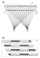
도 2(A) 및 도 2(B)는, 도 1(A) 내지 도 1(C)에서 도시한 표시 장치의 구동 방법예를 도시한 모식도이다. 구체적으로는, 도 2(A)는 도 1(A) 내지 도 1(C)에서 도시한 표시 장치에서 매트릭스 형상으로 배치된 복수의 화소(100)의 행 방향을 따른 단면을 도시한 모식도이고, 도 2(B)는 도 2(A)에서 도시한 셔터 패널(20)을 확대한 도면이다. 또한, 도 2(A) 및 도 2(B)는 위치 정보 검출 수단(30)에 의하여 검출된 위치 정보에 의거하여 시인자가 기준 위치에 존재한다고 표시 장치가 인정한 경우의 구동 방법예를 도시한 도면이다.2A and 2B are schematic diagrams showing an example of a method of driving the display device shown in Figs. 1A to 1C. Specifically, FIG. 2A is a schematic diagram showing a cross section along the row direction of a plurality of
또한, 도 2(A)의 표시 패널(10) 내에 부기된 L1 내지 L6 각각은 왼쪽 눈용 표시를 행하는 화소(100)를 나타내고, R1 내지 R6 각각은 오른쪽 눈용 표시를 행하는 화소(100)를 나타낸다. 또한, 도 2(A) 및 도 2(B)에서 도시한 셔터 패널(20) 내에 부기된 LA 내지 LZ 각각은 시인자 측에서 봐서 셔터 패널(20)의 왼쪽에 존재하는 투광 상태 또는 차광 상태의 선택이 가능한 영역을 나타내고, RA 내지 RZ 각각은 시인자 측에서 봐서 셔터 패널(20)의 오른쪽에 존재하는 투광 상태 또는 차광 상태의 선택이 가능한 영역을 나타낸다(도 2(A)에서는 LA 및 RZ 이외의 부호는 부기하지 않았음). 또한, 영역 LA 내지 영역 RZ의 각각에서 영역 내가 공백인 영역은 투광 상태인 것(상기 영역에 존재하는 투광성을 갖는 전극(200)에 투광 신호가 입력되는 것)을 나타내고, 영역 내에 사선이 부기된 영역은 차광 상태인 것(상기 영역에 존재하는 투광성을 갖는 전극(200)에 차광 신호가 입력되는 것)을 나타낸다. 또한, 도 2(A)에서는 시인자의 왼쪽 눈(41) 및 오른쪽 눈(42)도 부기하였다.In addition, each of L1 to L6 added in the
도 2(A) 및 도 2(B)에서 도시한 구동 방법예에 있어서는, 시인자 측에서 봐서 표시 패널(10)의 왼쪽 단(端)에 배치된 열로부터 기산하여 홀수 열에 배치된 복수의 화소(화소(L1) 내지 화소(L6))에서 왼쪽 눈용 표시를 행하고, 짝수 열에 배치된 복수의 화소(화소(R1) 내지 화소(R6))에서 오른쪽 눈용 표시를 행한다. 또한, 도 2(A) 및 도 2(B)에서 도시한 구동 방법예에 있어서는, 셔터 패널(20)에서의 영역(LA) 내지 영역(LD), 영역(LI) 내지 영역(LL), 영역(LQ) 내지 영역(LT), 영역(LY) 내지 영역(RB), 영역(RG) 내지 영역(RJ), 영역(RO) 내지 영역(RR), 영역(RW) 내지 영역(RZ)이 투광 상태이고, 영역(LE) 내지 영역(LH), 영역(LM) 내지 영역(LP), 영역(LU) 내지 영역(LX), 영역(RC) 내지 영역(RF), 영역(RK) 내지 영역(RN), 영역(RS) 내지 영역(RV)이 차광 상태이다. 이로써, 왼쪽 눈용 표시를 행하는 화소가 오른쪽 눈(42)에 시인되는 것을 방지하고 오른쪽 눈용 표시를 행하는 화소가 왼쪽 눈(41)에 시인되는 것을 방지할 수 있다.In the driving method examples shown in Figs. 2A and 2B, a plurality of pixels arranged in odd columns calculated from a column arranged at the left end of the
구체적으로는, 영역(LE) 내지 영역(LH)이 차광 상태가 됨으로써, 화소(R1)가 왼쪽 눈(41)에 시인되는 것을 방지하고 화소(L1)가 오른쪽 눈(42)에 시인되는 것을 방지할 수 있다. 또한, 영역(LM) 내지 영역(LP)이 차광 상태가 됨으로써, 화소(R2)가 왼쪽 눈(41)에 시인되는 것을 방지하고 화소(L2)가 오른쪽 눈(42)에 시인되는 것을 방지할 수 있다. 또한, 영역(LU) 내지 영역(LX)이 차광 상태가 됨으로써, 화소(R3)가 왼쪽 눈(41)에 시인되는 것을 방지하고 화소(L3)가 오른쪽 눈(42)에 시인되는 것을 방지할 수 있다. 또한, 영역(RC) 내지 영역(RF)이 차광 상태가 됨으로써, 화소(R4)가 왼쪽 눈(41)에 시인되는 것을 방지하고 화소(L4)가 오른쪽 눈(42)에 시인되는 것을 방지할 수 있다. 또한, 영역(RK) 내지 영역(RN)이 차광 상태가 됨으로써, 화소(R5)가 왼쪽 눈(41)에 시인되는 것을 방지하고 화소(L5)가 오른쪽 눈(42)에 시인되는 것을 방지할 수 있다. 또한, 영역(RS) 내지 영역(RV)이 차광 상태가 됨으로써, 화소(R6)가 왼쪽 눈(41)에 시인되는 것을 방지하고 화소(L6)가 오른쪽 눈(42)에 시인되는 것을 방지할 수 있다.Specifically, the area LE to the area LH are in a light shielding state, thereby preventing the pixel R1 from being visually recognized by the
<표시 장치의 구동 방법예 2(시점이 기준 위치에서 왼쪽으로 이동한 경우)><Driving Method Example 2 of Display Device (When Viewpoint Moved Leftward from Reference Position)>
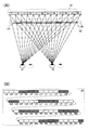
도 3(A) 및 도 3(B)는, 도 1(A) 내지 도 1(C)에서 도시한 표시 장치의 구동 방법예를 도시한 모식도이다. 또한, 도 3(A) 및 도 3(B)에서 도시한 구동 방법예는, 도 2(A) 및 도 2(B)에서 도시한 구동 방법예와는 시점이 상이하다(도 3(A) 중에 점선으로 나타내어진 왼쪽 눈 및 오른쪽 눈이 도 2(A)에서 도시한 시점). 구체적으로는, 도 3(A) 및 도 3(B)는, 위치 정보 검출 수단(30)에 의하여 검출된 위치 정보에 의거하여, 시인자가 기준 위치에서 왼쪽으로 이동한 위치에 존재한다고 표시 장치가 인정한 경우의 구동 방법예를 도시한 도면이다.3A and 3B are schematic diagrams showing an example of a method of driving the display device shown in Figs. 1A to 1C. The driving method examples shown in FIGS. 3A and 3B are different from the driving method examples shown in FIGS. 2A and 2B (FIG. 3A). The left eye and the right eye, shown by dotted lines, shown in FIG. 2 (A). Specifically, FIG. 3A and FIG. 3B show that the display device exists at a position where the viewer moves to the left from the reference position based on the positional information detected by the positional
또한, 도 3(A) 및 도 3(B) 중의 부호(L1 내지 L6 등) 등은, 도 2(A) 및 도 2(B)에서의 상기 부호 등과 같은 구성 요소를 의미한다.In addition, the code | symbol (L1-L6 etc.) etc. in FIG.3 (A) and FIG.3 (B) mean the component same as the said code | symbol in FIG.2 (A) and FIG.2 (B).
도 3(A) 및 도 3(B)에서 도시한 구동 방법예에서는, 표시 패널(10)이 도 2(A)에서 도시한 표시 패널(10)과 같은 표시를 행한다. 또한, 도 3(A) 및 도 3(B)에서 도시한 구동 방법예에서는, 셔터 패널(20)에서의 영역(LA) 내지 영역(LC), 영역(LH) 내지 영역(LK), 영역(LP) 내지 영역(LS), 영역(LX) 내지 영역(RA), 영역(RF) 내지 영역(RI), 영역(RN) 내지 영역(RQ), 영역(RV) 내지 영역(RY)이 투광 상태가 되고, 영역(LD) 내지 영역(LG), 영역(LL) 내지 영역(LO), 영역(LT) 내지 영역(LW), 영역(RB) 내지 영역(RE), 영역(RJ) 내지 영역(RM), 영역(RR) 내지 영역(RU), 영역(RZ)이 차광 상태가 된다. 도 2(A) 및 도 2(B)에서 도시한 구동 방법예의 셔터 패널(20)과 비교하면, 도 3(A) 및 도 3(B)에서 도시한 구동 방법예에서는 셔터 패널(20)에서의 영역(LD), 영역(LL), 영역(LT), 영역(RB), 영역(RJ), 영역(RR), 영역(RZ)이 차광 상태가 되고, 영역(LH), 영역(LP), 영역(LX), 영역(RF), 영역(RN), 영역(RV)이 투광 상태가 되는 점에서 상이하다. 단적으로 말하면, 도 3(A) 및 도 3(B)에서 도시한 구동 방법예에서는, 차광 상태가 되는 영역이 왼쪽으로 영역 하나분 이동한 점에서 도 2(A) 및 도 2(B)에서 도시한 구동 방법예와 상이하다. 이로써, 왼쪽 눈용 표시를 행하는 화소가 오른쪽 눈(42)에 시인되는 것을 방지하고 오른쪽 눈용 표시를 행하는 화소가 왼쪽 눈(41)에 시인되는 것을 방지할 수 있다.In the drive method examples shown in Figs. 3A and 3B, the
구체적으로는, 영역(LD) 내지 영역(LG)이 차광 상태가 됨으로써, 화소(R1)가 왼쪽 눈(41)에 시인되는 것을 방지하고 화소(L1)가 오른쪽 눈(42)에 시인되는 것을 방지할 수 있다. 또한, 영역(LL) 내지 영역(LO)이 차광 상태가 됨으로써, 화소(R2)가 왼쪽 눈(41)에 시인되는 것을 방지하고 화소(L2)가 오른쪽 눈(42)에 시인되는 것을 방지할 수 있다. 또한, 영역(LT) 내지 영역(LW)이 차광 상태가 됨으로써, 화소(R3)가 왼쪽 눈(41)에 시인되는 것을 방지하고 화소(L3)가 오른쪽 눈(42)에 시인되는 것을 방지할 수 있다. 또한, 영역(RB) 내지 영역(RE)이 차광 상태가 됨으로써, 화소(R4)가 왼쪽 눈(41)에 시인되는 것을 방지하고 화소(L4)가 오른쪽 눈(42)에 시인되는 것을 방지할 수 있다. 또한, 영역(RJ) 내지 영역(RM)이 차광 상태가 됨으로써, 화소(R5)가 왼쪽 눈(41)에 시인되는 것을 방지하고 화소(L5)가 오른쪽 눈(42)에 시인되는 것을 방지할 수 있다. 또한, 영역(RR) 내지 영역(RU)이 차광 상태가 됨으로써, 화소(R6)가 왼쪽 눈(41)에 시인되는 것을 방지하고 화소(L6)가 오른쪽 눈(42)에 시인되는 것을 방지할 수 있다.Specifically, the area LD to the area LG become a light shielding state, thereby preventing the pixel R1 from being visually recognized by the
<표시 장치의 구동 방법예 3(시점이 기준 위치에서 오른쪽으로 이동한 경우)><Example 3 of driving method of a display apparatus (when a viewpoint moves to the right from a reference position)>
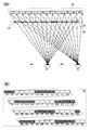
도 4(A) 및 도 4(B)는, 도 1(A) 내지 도 1(C)에서 도시한 표시 장치의 구동 방법예를 도시한 모식도이다. 또한, 도 4(A) 및 도 4(B)에서 도시한 구동 방법예는, 도 2(A) 및 도 2(B), 또는 도 3(A) 및 도 3(B)에서 도시한 구동 방법예와는 시점이 상이하다(도 4(A) 중에 점선으로 나타내어진 왼쪽 눈 및 오른쪽 눈이 도 2(A)에서 도시한 시점). 구체적으로는, 도 4(A) 및 도 4(B)는, 위치 정보 검출 수단(30)에 의하여 검출된 위치 정보에 의거하여, 시인자가 기준 위치에서 오른쪽으로 이동한 위치에 존재한다고 표시 장치가 인정한 경우의 구동 방법예를 도시한 도면이다. 또한, 도 4(A) 및 도 4(B)에서 도시한 구동 방법예에서의 시점 위치와 도 2(A) 및 도 2(B)에서 도시한 구동 방법예에서의 시점 위치의 변위량은, 도 3(A) 및 도 3(B)에서 도시한 구동 방법예에서의 시점 위치와 도 2(A) 및 도 2(B)에서 도시한 구동 방법예에서의 시점 위치의 변위량보다 크다.4A and 4B are schematic diagrams showing an example of a method of driving the display device shown in Figs. 1A to 1C. In addition, the driving method example shown in FIG. 4 (A) and FIG. 4 (B) is the driving method shown in FIG. 2 (A) and FIG. 2 (B) or FIG. 3 (A) and FIG. 3 (B). The viewpoint is different from the example (the left eye and the right eye shown by the dotted lines in FIG. 4 (A) are shown in FIG. 2 (A)). Specifically, Figs. 4A and 4B show that the display device exists at a position where the viewer moves to the right from the reference position based on the positional information detected by the positional
또한, 도 4(A) 및 도 4(B) 중의 부호(L1 내지 L6 등) 등은, 도 2(A) 및 도 2(B)에서의 상기 부호 등과 같은 구성 요소를 의미한다.In addition, the code | symbol (L1-L6 etc.) etc. in FIG.4 (A) and FIG.4 (B) mean the component same as the said code | symbol in FIG.2 (A) and FIG.2 (B).
도 4(A) 및 도 4(B)에서 도시한 구동 방법예에서는, 표시 패널(10)이 도 2(A)에서 도시한 표시 패널(10)과 같은 표시를 행한다. 또한, 도 4(A) 및 도 4(B)에서 도시한 구동 방법예에서는, 셔터 패널(20)에서의 영역(LC) 내지 영역(LF), 영역(LK) 내지 영역(LN), 영역(LS) 내지 영역(LV), 영역(RA) 내지 영역(RD), 영역(RI) 내지 영역(RL), 영역(RQ) 내지 영역(RT), 영역(RY), 영역(RZ)이 투광 상태가 되고, 영역(LA), 영역(LB), 영역(LG) 내지 영역(LJ), 영역(LO) 내지 영역(LR), 영역(LW) 내지 영역(LZ), 영역(RE) 내지 영역(RH), 영역(RM) 내지 영역(RP), 영역(RU) 내지 영역(RX)이 차광 상태가 된다. 도 2(A) 및 도 2(B)에서 도시한 구동 방법예의 셔터 패널(20)과 비교하면, 도 4(A) 및 도 4(B)에서 도시한 구동 방법예에서는 셔터 패널(20)에서의 영역(LA), 영역(LB), 영역(LI), 영역(LJ), 영역(LQ), 영역(LR), 영역(LY), 영역(LZ), 영역(RG), 영역(RH), 영역(RO), 영역(RP), 영역(RW), 영역(RX)이 차광 상태가 되고, 영역(LE), 영역(LF), 영역(LM), 영역(LN), 영역(LU), 영역(LV), 영역(RC), 영역(RD), 영역(RK), 영역(RL), 영역(RS), 영역(RT)이 투광 상태가 되는 점에서 상이하다. 단적으로 말하면, 도 4(A) 및 도 4(B)에서 도시한 구동 방법예에서는, 차광 상태가 되는 영역이 오른쪽으로 영역 2개분 이동한 점에서 도 2(A) 및 도 2(B)에서 도시한 구동 방법예와 상이하다. 이로써, 왼쪽 눈용 표시를 행하는 화소가 오른쪽 눈(42)에 시인되는 것을 방지하고 오른쪽 눈용 표시를 행하는 화소가 왼쪽 눈(41)에 시인되는 것을 방지할 수 있다.In the drive method examples shown in Figs. 4A and 4B, the
구체적으로는, 영역(LG) 내지 영역(LJ)이 차광 상태가 됨으로써, 화소(R1)가 왼쪽 눈(41)에 시인되는 것을 방지하고 화소(L1)가 오른쪽 눈(42)에 시인되는 것을 방지할 수 있다. 또한, 영역(LO) 내지 영역(LR)이 차광 상태가 됨으로써, 화소(R2)가 왼쪽 눈(41)에 시인되는 것을 방지하고 화소(L2)가 오른쪽 눈(42)에 시인되는 것을 방지할 수 있다. 또한, 영역(LW) 내지 영역(LZ)이 차광 상태가 됨으로써, 화소(R3)가 왼쪽 눈(41)에 시인되는 것을 방지하고 화소(L3)가 오른쪽 눈(42)에 시인되는 것을 방지할 수 있다. 또한, 영역(RE) 내지 영역(RH)이 차광 상태가 됨으로써, 화소(R4)가 왼쪽 눈(41)에 시인되는 것을 방지하고 화소(L4)가 오른쪽 눈(42)에 시인되는 것을 방지할 수 있다. 또한, 영역(RM) 내지 영역(RP)이 차광 상태가 됨으로써, 화소(R5)가 왼쪽 눈(41)에 시인되는 것을 방지하고 화소(L5)가 오른쪽 눈(42)에 시인되는 것을 방지할 수 있다. 또한, 영역(RU) 내지 영역(RX)이 차광 상태가 됨으로써, 화소(R6)가 왼쪽 눈(41)에 시인되는 것을 방지하고 화소(L6)가 오른쪽 눈(42)에 시인되는 것을 방지할 수 있다.Specifically, the area LG to the area LJ are in a light shielding state, thereby preventing the pixel R1 from being visually recognized by the
<표시 장치의 구동 방법예 4(시점이 기준 위치보다 근접한 경우)><Driving method example 4 of the display device (when the viewpoint is closer than the reference position)>
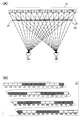
도 5(A) 및 도 5(B)는, 도 1(A) 내지 도 1(C)에서 도시한 표시 장치의 구동 방법예를 도시한 모식도이다. 또한, 도 5(A) 및 도 5(B)에서 도시한 구동 방법예는, 도 2(A) 및 도 2(B), 도 3(A) 및 도 3(B), 또는 도 4(A) 및 도 4(B)에서 도시한 구동 방법예와는 시점이 상이하다(도 5(A) 중에 점선으로 나타내어진 왼쪽 눈 및 오른쪽 눈이 도 2(A)에서 도시한 시점). 구체적으로는, 도 5(A) 및 도 5(B)는, 위치 정보 검출 수단(30)에 의하여 검출된 위치 정보에 의거하여, 시인자가 기준 위치보다 근접한 위치에 존재한다고 표시 장치가 인정한 경우의 구동 방법예를 도시한 도면이다.5A and 5B are schematic diagrams showing an example of a method of driving the display device shown in Figs. 1A to 1C. In addition, the driving method example shown in FIG. 5 (A) and FIG. 5 (B) is the same as FIG. 2 (A) and FIG. 2 (B), FIG. 3 (A) and FIG. 3 (B), or FIG. 4 (A). ) And the driving method example shown in FIG. 4 (B) are different from those of the driving method shown in FIG. 4B (the left eye and the right eye shown by dotted lines in FIG. 5A are shown in FIG. 2A). Specifically, Figs. 5A and 5B show the case where the display apparatus recognizes that the viewer is located at a position closer to the reference position based on the position information detected by the position
또한, 도 5(A) 및 도 5(B) 중의 부호(L1 내지 L6 등) 등은, 도 2(A) 및 도 2(B)에서의 상기 부호 등과 같은 구성 요소를 의미한다.In addition, the code | symbol (L1-L6 etc.) etc. in FIG.5 (A) and FIG.5 (B) mean the component like the said code | symbol in FIG.2 (A) and FIG.2 (B).
도 5(A) 및 도 5(B)에서 도시한 구동 방법예에서는, 표시 패널(10)이 도 2(A)에서 도시한 표시 패널(10)과 같은 표시를 행한다. 또한, 도 5(A) 및 도 5(B)에서 도시한 구동 방법예에서는, 도 2(A) 및 도 2(B)에서 도시한 셔터 패널(20)에서 차광 상태가 되는 영역 모두가 차광 상태가 된다. 또한, 도 5(A) 및 도 5(B)에서 도시한 구동 방법예에서는, 셔터 패널(20)에서의 영역(LI), 영역(LQ), 영역(LY), 영역(RB), 영역(RJ), 영역(RR)이 차광 상태가 된다. 단적으로 말하면, 도 5(A) 및 도 5(B)에서 도시한 구동 방법예에서는, 시인자 측에서 봐서 셔터 패널(20)의 왼쪽에 존재하는 차광 영역이 오른쪽으로 영역 하나분 확장되고, 시인자 측에서 봐서 셔터 패널(20)의 오른쪽에 존재하는 차광 영역이 왼쪽으로 영역 하나분 확장된 점에서 도 2(A) 및 도 2(B)에서 도시한 구동 방법예와 상이하다. 이로써, 왼쪽 눈용 표시를 행하는 화소가 오른쪽 눈(42)에 시인되는 것을 방지하고 오른쪽 눈용 표시를 행하는 화소가 왼쪽 눈(41)에 시인되는 것을 방지할 수 있다.In the driving method examples shown in Figs. 5A and 5B, the
구체적으로는, 영역(LE) 내지 영역(LI)이 차광 상태가 됨으로써, 화소(R1)가 왼쪽 눈(41)에 시인되는 것을 방지하고 화소(L1)가 오른쪽 눈(42)에 시인되는 것을 방지할 수 있다. 또한, 영역(LM) 내지 영역(LQ)이 차광 상태가 됨으로써, 화소(R2)가 왼쪽 눈(41)에 시인되는 것을 방지하고 화소(L2)가 오른쪽 눈(42)에 시인되는 것을 방지할 수 있다. 또한, 영역(LU) 내지 영역(LY)이 차광 상태가 됨으로써, 화소(R3)가 왼쪽 눈(41)에 시인되는 것을 방지하고 화소(L3)가 오른쪽 눈(42)에 시인되는 것을 방지할 수 있다. 또한, 영역(RB) 내지 영역(RF)이 차광 상태가 됨으로써, 화소(R4)가 왼쪽 눈(41)에 시인되는 것을 방지하고 화소(L4)가 오른쪽 눈(42)에 시인되는 것을 방지할 수 있다. 또한, 영역(RJ) 내지 영역(RN)이 차광 상태가 됨으로써, 화소(R5)가 왼쪽 눈(41)에 시인되는 것을 방지하고 화소(L5)가 오른쪽 눈(42)에 시인되는 것을 방지할 수 있다. 또한, 영역(RR) 내지 영역(RV)이 차광 상태가 됨으로써, 화소(R6)가 왼쪽 눈(41)에 시인되는 것을 방지하고 화소(L6)가 오른쪽 눈(42)에 시인되는 것을 방지할 수 있다.Specifically, the area LE to the area LI are in a light shielding state, thereby preventing the pixel R1 from being visually recognized by the
<표시 장치의 구동 방법예 5(시점이 기준 위치보다 먼 경우)><Example 5 of driving method of a display apparatus (when a viewpoint is further from a reference position)>
도 6(A) 및 도 6(B)는, 도 1(A) 내지 도 1(C)에서 도시한 표시 장치의 구동 방법예를 도시한 모식도이다. 또한, 도 6(A) 및 도 6(B)에서 도시한 구동 방법예는, 도 2(A) 및 도 2(B), 도 3(A) 및 도 3(B), 도 4(A) 및 도 4(B), 또는 도 5(A) 및 도 5(B)에서 도시한 구동 방법예와는 시점이 상이하다(도 6(A) 중에 점선으로 나타내어진 왼쪽 눈 및 오른쪽 눈이 도 2(A)에서 도시한 시점). 구체적으로는, 도 6(A) 및 도 6(B)는, 위치 정보 검출 수단(30)에 의하여 검출된 위치 정보에 의거하여, 시인자가 기준 위치보다 먼 위치에 존재한다고 표시 장치가 인정한 경우의 구동 방법예를 도시한 도면이다.6A and 6B are schematic diagrams showing an example of a method of driving the display device shown in Figs. 1A to 1C. 6 (A) and 6 (B) are examples of the driving method shown in Figs. 2 (A) and 2 (B), 3 (A) and 3 (B) and Fig. 4 (A). And a viewpoint different from the driving method example shown in FIG. 4 (B) or FIG. 5 (A) and FIG. 5 (B) (left eye and right eye shown by dotted lines in FIG. The time point shown in (A)). Specifically, Figs. 6A and 6B show the case where the display apparatus recognizes that the viewer exists at a position farther from the reference position based on the positional information detected by the positional
또한, 도 6(A) 및 도 6(B) 중의 부호(L1 내지 L6 등) 등은, 도 2(A) 및 도 2(B)에서의 상기 부호 등과 같은 구성 요소를 의미한다.In addition, the code | symbol (L1-L6 etc.) etc. in FIG.6 (A) and FIG.6 (B) mean the component like the said code | symbol etc. in FIG.2 (A) and FIG.2 (B).
도 6(A) 및 도 6(B)에서 도시한 구동 방법예에서는, 표시 패널(10)이 도 2(A)에서 도시한 표시 패널(10)과 같은 표시를 행한다. 또한, 도 6(A) 및 도 6(B)에서 도시한 구동 방법예에서는, 도 2(A) 및 도 2(B)에서 도시한 셔터 패널(20)에서 차광 상태가 되는 영역 모두가 차광 상태가 된다. 또한, 도 6(A) 및 도 6(B)에서 도시한 구동 방법예에서는, 셔터 패널(20)에서의 영역(LD), 영역(LL), 영역(LT), 영역(RG), 영역(RO), 영역(RW)이 차광 상태가 된다. 단적으로 말하면, 도 6(A) 및 도 6(B)에서 도시한 구동 방법예에서는, 시인자 측에서 봐서 셔터 패널(20)의 왼쪽에 존재하는 차광 영역이 왼쪽으로 영역 하나분 확장되고, 시인자 측에서 봐서 셔터 패널(20)의 오른쪽에 존재하는 차광 영역이 오른쪽으로 영역 하나분 확장된 점에서 도 2(A) 및 도 2(B)에서 도시한 구동 방법예와 상이하다. 이로써, 왼쪽 눈용 표시를 행하는 화소가 오른쪽 눈(42)에 시인되는 것을 방지하고 오른쪽 눈용 표시를 행하는 화소가 왼쪽 눈(41)에 시인되는 것을 방지할 수 있다.In the driving method examples shown in Figs. 6A and 6B, the
구체적으로는, 영역(LD) 내지 영역(LH)이 차광 상태가 됨으로써, 화소(R1)가 왼쪽 눈(41)에 시인되는 것을 방지하고 화소(L1)가 오른쪽 눈(42)에 시인되는 것을 방지할 수 있다. 또한, 영역(LL) 내지 영역(LP)이 차광 상태가 됨으로써, 화소(R2)가 왼쪽 눈(41)에 시인되는 것을 방지하고 화소(L2)가 오른쪽 눈(42)에 시인되는 것을 방지할 수 있다. 또한, 영역(LT) 내지 영역(LX)이 차광 상태가 됨으로써, 화소(R3)가 왼쪽 눈(41)에 시인되는 것을 방지하고 화소(L3)가 오른쪽 눈(42)에 시인되는 것을 방지할 수 있다. 또한, 영역(RC) 내지 영역(RG)이 차광 상태가 됨으로써, 화소(R4)가 왼쪽 눈(41)에 시인되는 것을 방지하고 화소(L4)가 오른쪽 눈(42)에 시인되는 것을 방지할 수 있다. 또한, 영역(RK) 내지 영역(RO)이 차광 상태가 됨으로써, 화소(R5)가 왼쪽 눈(41)에 시인되는 것을 방지하고 화소(L5)가 오른쪽 눈(42)에 시인되는 것을 방지할 수 있다. 또한, 영역(RS) 내지 영역(RW)이 차광 상태가 됨으로써, 화소(R6)가 왼쪽 눈(41)에 시인되는 것을 방지하고 화소(L6)가 오른쪽 눈(42)에 시인되는 것을 방지할 수 있다.Specifically, the area LD to the area LH are in a light shielding state, thereby preventing the pixel R1 from being visually recognized by the
<본 명세서에 기재되는 표시 장치><Display apparatus described in this specification>
본 명세서에 기재되는 표시 장치는, 시인자의 위치 정보를 검출하는 수단을 갖는다. 그리고, 상기 위치 정보에 의거하여 시차 배리어를 형성할 수 있다(도 2(A) 내지 도 6(B) 참조). 따라서, 상기 시인자에 대한 크로스토크의 발생을 억제할 수 있게 된다.The display device described in this specification has a means for detecting the positional information of the viewer. And a parallax barrier can be formed based on the said positional information (refer FIG. 2 (A)-FIG. 6 (B)). Therefore, it is possible to suppress the occurrence of crosstalk to the viewer.
<표시 패널의 구체적인 예><Specific example of display panel>
상술한 표시 장치에서는, 스트라이프 형상의 시차 배리어가 매트릭스 형상으로 배치된 복수의 화소(100)의 열 방향과 평행 또는 대략 평행으로 형성된다. 따라서, 상술한 표시 장치에서는, 시인자의 시점에 따라, 오른쪽(왼쪽) 눈용 표시를 행하는 각 화소(100)의 오른쪽 영역의 일부 또는 왼쪽 영역의 일부가 오른쪽(왼쪽) 눈에 시인되지 않을 가능성이 있다. 따라서, 상술한 표시 장치에서는, 화소(100)의 일부가 시인되지 않는 상태에서도 상기 화소(100)에서 행해지는 원하는 색의 표시가 시인자에게 시인되도록 설계하는 것이 바람직하다.In the display device described above, a stripe parallax barrier is formed in parallel or substantially parallel to the column direction of the plurality of
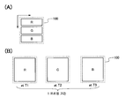
도 7(A) 및 도 7(B)는 화소(100)의 오른쪽 영역의 일부 또는 왼쪽 영역의 일부가 오른쪽(왼쪽) 눈에 시인되지 않는 상태라도 시인자에게 원하는 색의 표시를 시인시킬 수 있는 화소(100)의 구체적인 예를 도시한 도면이다.7 (A) and 7 (B) illustrate that the viewer can visually display a desired color even when a part of the right area or a part of the left area of the
구체적으로는, 도 7(A)에서 도시한 화소(100)는, 열 방향으로 배치되는, 적색 표시를 행하는 부화소(도면 주에서 「R」이라고 부기함)와, 녹색 표시를 행하는 부화소(도면 중에서 「G」라고 부기함)와, 청색 표시를 행하는 부화소(도면 중에서 「B」라고 부기함)를 갖는다. 그리고, 도 7(A)에서 도시한 화소(100)에서는, 이들 부화소의 표시를 조정함으로써 원하는 색을 표시할 수 있다. 또한, 적색 표시를 행하는 부화소는 적색을 나타내는 빛 이외의 가시광 영역의 파장을 흡수하는 컬러 필터를 상기 부화소에 제공하거나, 또는 적색을 나타내는 빛을 발광하는 소자를 상기 부화소에 제공하는 등에 의하여 형성할 수 있다. 또한, 녹색 표시 또는 청색 표시를 행하는 부화소에 대하여도 마찬가지다. 도 7(A)에서 도시한 화소(100)에서는, 만약에 화소(100)의 오른쪽 영역의 일부 또는 왼쪽 영역의 일부가 시인되지 않은 경우라도 시인자가 각 부화소의 표시를 시인할 수 있다. 따라서, 시인자가 화소(100)에서의 색 표시를 시인할 수 있다.Specifically, the
또한, 도 7(B)에서 도시한 화소(100)는 적색 표시를 행하는 기간 T1과, 녹색 표시를 행하는 기간 T2와, 청색 표시를 행하는 기간 T3을 갖는다. 그리고, 도 7(B)에서 도시한 화소(100)에서는, 이들 기간에서 화소(100)를 순차적으로 표시시킴으로써(소위, 필드 시퀀셜 방식) 원하는 색을 표시할 수 있다. 또한, 도 7(B)에서 도시한 기간 T1 내지 기간 T3은 1 프레임 기간에 포함되는 기간이다. 도 7(B)에서 도시한 화소(100)에서는, 만약에 화소(100)의 오른쪽 영역의 일부 또는 왼쪽 영역의 일부가 시인되지 않은 상태에서도 시인자가 각 기간(기간 T1 내지 기간 T3)에서의 화소(100)의 표시를 시인할 수 있다. 따라서, 시인자가 화소(100)에서의 색 표시를 시인할 수 있다.In addition, the
<셔터 패널의 구체적인 예><Specific example of shutter panel>
도 8은 상술한 표시 장치가 갖는 셔터 패널(20)의 구체적인 예를 도시한 도면이다. 도 8에서 도시한 셔터 패널(20)은 복수의 투광성을 갖는 전극(200)과, 복수의 투광성을 갖는 전극(200) 각각에 대하여 독립적으로 신호를 출력하는 구동 회로(210)와, 구동 회로(210)에 대하여 외부 신호를 입력하는 플렉시블 프린트 기판(220)을 갖는다. 또한, 구동 회로(210)는 다수의 반도체 소자(트랜지스터 등)로 구성된다. 그리고, 상기 반도체 소자 및 복수의 투광성을 갖는 전극(200)은 동일 기판 위에 포토리소그래피법 등을 사용하여 형성할 수 있다.8 is a diagram illustrating a specific example of the
도 9(A)는 도 8에서 도시한 셔터 패널(20)과 상이한 셔터 패널(20)의 구체적인 예를 도시한 도면이다. 구체적으로는, 도 9(A)에서 도시한 셔터 패널(20)은, 구동 회로(210)와 복수의 투광성을 갖는 전극(200) 각각의 전기적 접속을 제어하는 복수의 트랜지스터(230)가 제공된 점에서 도 8에서 도시한 셔터 패널(20)과 상이하다. 또한, 트랜지스터(230)의 스위칭은 구동 회로(210)에 의하여 제어된다. 또한, 트랜지스터(230)는, 구동 회로(210)를 구성하는 반도체 소자 및 투광성을 갖는 전극(200)과 동일 기판 위에 포토리소그래피법 등을 사용하여 형성할 수 있다.FIG. 9A is a diagram showing a specific example of a
도 9(A)에서 도시한 트랜지스터(230)로서는, 실리콘 또는 게르마늄 등의 주기율표 제 14족 원소를 주된 구성 원소로 하는 반도체층, 또는 반도체 특성을 나타내는 산화물(이하, 산화물 반도체라고도 함)을 재료로 하는 반도체층(이하, 산화물 반도체층이라고도 함)에 채널이 형성된 박막 트랜지스터 등을 적용할 수 있다.As the
또한, 산화물 반도체는, 밴드 갭이 넓고, 또 진성 캐리어 밀도가 낮다는 특징을 갖는다. 따라서, 산화물 반도체층에 채널이 형성된 박막 트랜지스터에서는, 오프 전류를 매우 낮게 할 수 있다.In addition, the oxide semiconductor has a feature of having a wide band gap and low intrinsic carrier density. Therefore, in the thin film transistor in which the channel is formed in the oxide semiconductor layer, the off current can be made very low.
여기서, 셔터 패널(20)은 시차 배리어를 형성하거나 변형할 때, 정기적 또는 부정기적으로 구동하는 것이 요구된다. 바꿔 말하면, 셔터 패널(20)을 구동하는 것이 요구되는 기간은 셔터 패널(20)에 형성되는 시차 배리어의 형상이 유지되는 기간보다 현저히 짧아진다. 따라서, 셔터 패널(20)에 형성되는 시차 배리어의 형상이 유지되는 기간에서는 셔터 패널(20)에 포함된 복수의 전극에 대하여 신호를 출력하는 구동 회로에 대한 전원 전압의 공급을 정지하는 것이 바람직하고, 이것은 소비 전력을 저감하기 위해서다. 다만, 구동 회로에 대한 전원 전압의 공급을 정지하는 경우에는, 복수의 투광성을 갖는 전극 각각에서의 전위가 변동되어 시차 배리어의 형상이 유지되지 않을 개연성이 높아진다.Here, the
한편, 도 9(A)에서 도시한 셔터 패널(20)이 갖는 트랜지스터(230)로서 산화물 반도체층에 채널이 형성된 박막 트랜지스터를 적용하는 구성인 경우, 구동 회로에 대한 전원 전압의 공급을 정지하는 경우에도 복수의 전극 각각에서의 전위의 변동을 저감할 수 있다. 구체적으로는, 상기 구성을 갖는 표시 장치에서는, 도 9(B)에서 도시한 동작을 행할 수 있게 된다. 도 9(B)에서 도시한 바와 같이 상기 구성을 갖는 표시 장치에서는, 시차 배리어를 형성하거나 시차 배리어를 변형할 때의 전후의 기간에만 구동 회로에 대하여 전원 전압을 공급하고, 그 외 기간에서는 구동 회로에 대하여 전원 전압을 공급하지 않는 것이 가능하다. 또한, 시차 배리어의 형상이 유지되는 기간이 장기간에 걸치는 경우에는, 정기적 또는 임시적으로 구동 회로에 대하여 전원 전압을 공급하고, 복수의 전극에 대하여 동일 형상의 시차 배리어를 형성하기 위한 신호를 출력할 수도 있다.On the other hand, when the thin film transistor in which the channel is formed in the oxide semiconductor layer as the
<위치 정보 검출 수단의 구체적인 예><Specific example of positional information detecting means>
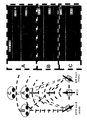
도 10은 상술한 표시 장치가 갖는 위치 정보 검출 수단(30)의 구체적인 예를 도시한 도면이다. 도 10에 도시한 위치 정보 검출 수단(30)은, 표시 패널(10)의 중앙상부에 제공되는 초음파 발신기(301)와, 표시 패널(10)의 양단상부에 제공되는 2개의 초음파 수신기, 즉 초음파 수신기(302L) 및 초음파 수신기(302R)를 갖는다. 도 10에 도시한 위치 정보 검출 수단(30)은, 초음파 발신기(301)로부터 초음파를 발신할 수 있다. 그리고, 초음파 수신기(302L) 및 초음파 수신기(302R)에서 시인자에 부딪쳐 반사된 초음파를 수신할 수 있다. 상술한 표시 장치는, 상기 수신된 초음파에 의거하여 시인자의 위치 정보를 검출할 수 있다.10 is a diagram showing a specific example of the positional
도 11은 도 10에서 도시한 위치 정보 검출 수단(30)에서의 시인자의 위치 정보의 검출을 자세히 도시한 도면이다. 도 11에서 A, B, C 각각은 시인자의 위치를 나타낸다. 구체적으로는, A는 시인자가 기준 위치에 있는 경우, B는 시인자가 A의 오른쪽에 있지만 표시 장치와의 거리는 A와 동등한 경우, C는 시인자가 A보다 먼 경우를 나타낸다.FIG. 11 is a diagram showing in detail the detection of the viewer's positional information in the positional
여기서, 시인자가 A 또는 C에 있는 경우, 표시 장치의 오른쪽에 제공된 초음파 수신기(도면 중에서 「수신:R」이라고 부기함)에서 수신되는 초음파(도면 중에서 「반사파:R」이라고 부기함)의 진폭과, 표시 장치의 왼쪽에 제공된 초음파 수신기(도면 중에서 「수신:L」이라고 부기함)에서 수신되는 초음파(도면 중에서 「반사파:L」이라고 부기함)의 진폭이 동등하다. 따라서, 표시 장치는 검출된 초음파에 의거하여 시인자가 기준 위치와 표시 장치의 중앙을 맺는 직선상에 있다고 인정할 수 있다.Here, when the viewer is at A or C, the amplitude of the ultrasonic wave received at the right side of the display device (referred to as "receive: R" in the figure) and the amplitude of the ultrasonic wave (referred to as "reflected wave: R" in the figure) The amplitudes of the ultrasonic waves received by the ultrasonic receiver (referred to as "received: L" in the figure) provided on the left side of the display device are referred to as "reflected wave: L" in the figure. Therefore, the display device can recognize that the viewer is on a straight line between the reference position and the center of the display device based on the detected ultrasonic waves.
또한, 시인자가 B에 있는 경우, 표시 장치의 오른쪽에 제공된 초음파 수신기에서 수신되는 초음파의 진폭이, 표시 장치의 왼쪽에 제공된 초음파 수신기에서 수신되는 초음파의 진폭보다 커진다. 따라서, 표시 장치는 검출된 초음파에 의거하여 시인자가 표시 장치의 오른쪽에 있다고 인정할 수 있다.In addition, when the viewer is at B, the amplitude of the ultrasonic wave received by the ultrasonic receiver provided on the right side of the display device is larger than the amplitude of the ultrasonic wave received by the ultrasonic receiver provided on the left side of the display device. Therefore, the display device can recognize that the viewer is on the right side of the display device based on the detected ultrasonic waves.
또한, 시인자가 A에 있는 경우와 시인자가 C에 있는 경우에서는, 표시 장치의 오른쪽에 제공된 초음파 수신기 및 왼쪽에 제공된 초음파 수신기에서 수신되는 초음파의 진폭이 상이하다. 따라서, 검출된 초음파에 의거하여 시인자와 표시 장치의 거리를 인정할 수 있다.In addition, in the case where the viewer is at A and the viewer is at C, the amplitudes of the ultrasonic waves received by the ultrasonic receiver provided on the right side of the display device and the ultrasonic receiver provided on the left side are different. Therefore, the distance between the viewer and the display device can be recognized based on the detected ultrasonic waves.
상술한 바와 같이, 도 10 및 도 11에서 도시한 위치 정보 검출 수단(30)에서는, 표시 장치와 시인자의 시점이 이루는 각도 및 표시 장치와 시인자 사이의 거리를 인정할 수 있다. 즉, 시인자의 위치 정보를 검출할 수 있다. 그리고, 상술한 표시 장치에서는, 상기 위치 정보에 의거하여 셔터 패널(20)에서의 시차 배리어를 형성할 수 있다.As described above, the positional
(실시예)(Example)
본 발명의 일 형태에 따른 표시 장치를 사용할 수 있는 전자 기기로서는, 휴대 전화, 휴대형 게임기, 휴대 정보 단말기, 전자 서적, 비디오 카메라, 디지털 스틸 카메라 등의 카메라 등을 들 수 있다. 이하에서는, 이들 전자 기기의 구체적인 예에 대하여 도 12(A) 및 도 12(B)를 참조하여 설명한다.Examples of the electronic device that can use the display device of one embodiment of the present invention include a mobile phone, a portable game machine, a portable information terminal, an electronic book, a video camera, a camera such as a digital still camera, and the like. Hereinafter, specific examples of these electronic devices will be described with reference to FIGS. 12A and 12B.
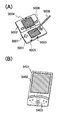
도 12(A)는 휴대형 게임기이며, 하우징(5001), 하우징(5002), 표시부(5003), 표시부(5004), 마이크로폰(5005), 스피커(5006), 조작 키(5007), 스타일러스(stylus)(5008) 등을 갖는다. 본 발명의 일 형태에 따른 표시 장치는 표시부(5003) 또는 표시부(5004)에 사용할 수 있다. 표시부(5003) 또는 표시부(5004)에 본 발명의 일 형태에 따른 표시 장치를 사용함으로써, 편리성이 뛰어난 3차원 화상 표시를 행할 수 있는 휴대형 게임기를 제공할 수 있다. 또한, 도 12(A)에 도시한 휴대형 게임기는 2개의 표시부, 즉 표시부(5003) 및 표시부(5004)를 갖고 있지만, 휴대형 게임기가 갖는 표시부의 개수는 이것에 한정되지 않는다.Fig. 12A is a portable game machine, which includes a
도 12(B)는 휴대 정보 단말이며, 하우징(5401), 표시부(5402), 조작 키(5403) 등을 갖는다. 본 발명의 일 형태에 따른 표시 장치는 표시부(5402)에 사용할 수 있다. 표시부(5402)에 본 발명의 일 형태에 따른 표시 장치를 사용함으로써, 편리성이 뛰어난 3차원 화상 표시를 행할 수 있는 휴대 정보 단말을 제공할 수 있다.
FIG. 12B is a portable information terminal, and includes a
10: 표시 패널 20: 셔터 패널
30: 위치 정보 검출 수단 41: 왼쪽 눈
42: 오른쪽 눈 100: 화소
200: 투광성을 갖는 전극 202: 액정
204: 전극 205: 기판
206: 기판 210: 구동 회로
220: 플렉시블 프린트 기판 230: 트랜지스터
301: 초음파 발신기 302L: 초음파 수신기
302R: 초음파 수신기 5001: 하우징
5002: 하우징 5003: 표시부
5004: 표시부 5005: 마이크로폰
5006: 스피커 5007: 조작 키
5008: 스타일러스 5401: 하우징
5402: 표시부 5403: 조작 키10: display panel 20: shutter panel
30: location information detecting means 41: left eye
42: right eye 100: pixels
200: electrode having light transparency 202: liquid crystal
204: electrode 205: substrate
206: substrate 210: drive circuit
220: flexible printed circuit board 230: transistor
301:
302R: Ultrasonic Receiver 5001: Housing
5002: housing 5003: display
5004: display portion 5005: microphone
5006: speaker 5007: operation keys
5008: stylus 5401: housing
5402: Display portion 5403: Operation keys
Claims (10)
복수의 화소들을 포함한 표시 패널과;
구동 회로, 액정, 및 스트라이프 형상으로 배치된 투광성을 갖는 전극들을 포함한 셔터 패널과;
시인자의 위치 정보를 검출하는 위치 정보 검출기를 포함하고,
상기 셔터 패널은 상기 표시 패널의 표시면 측에 배치되고,
상기 투광성을 갖는 전극들 중 하나의 폭은 상기 복수의 화소들 중 하나의 폭보다 작고,
상기 구동 회로는 상기 투광성을 갖는 전극들에 시차 배리어를 형성하기 위한 신호들을 선택적으로 출력하고,
상기 시차 배리어는 상기 검출된 위치 정보에 의거하여 형상을 변경할 수 있는, 표시 장치.
In a display device,
A display panel including a plurality of pixels;
A shutter panel including a drive circuit, a liquid crystal, and translucent electrodes arranged in a stripe shape;
A location information detector for detecting location information of the viewer,
The shutter panel is disposed on the display surface side of the display panel,
A width of one of the translucent electrodes is less than a width of one of the plurality of pixels,
The driving circuit selectively outputs signals for forming a parallax barrier on the translucent electrodes,
And the parallax barrier can change shape based on the detected positional information.
상기 복수의 화소들은 제 1 열에 제 1 화소들을 포함하고, 제 2 열에 제 2 화소들을 포함하고,
상기 제 1 화소들은 상기 시인자의 왼쪽 눈용의 제 1 표시를 행하고,
상기 제 2 화소들은 상기 시인자의 오른쪽 눈용의 제 2 표시를 행하는, 표시 장치.
The method of claim 1,
The plurality of pixels includes first pixels in a first column, second pixels in a second column,
The first pixels perform a first display of the viewer's left eye,
And the second pixels perform a second display for the right eye of the viewer.
상기 위치 정보 검출기는 검출 매체로서 초음파를 이용하는, 표시 장치.
The method of claim 1,
And the position information detector uses ultrasonic waves as a detection medium.
상기 셔터 패널은 채널로서의 역할을 갖는 산화물 반도체층을 각각 포함한 트랜지스터들을 더 포함하고,
상기 트랜지스터들 중 하나가 상기 구동 회로와 상기 투광성을 갖는 전극들 중 하나 사이에 위치된, 표시 장치.
The method of claim 1,
The shutter panel further includes transistors each including an oxide semiconductor layer having a role as a channel,
Wherein one of the transistors is located between the drive circuit and one of the translucent electrodes.
상기 셔터 패널은 전극을 더 포함하고,
상기 액정은 상기 투광성을 갖는 전극들 중 하나와 상기 전극 사이에 개재(介在)된, 표시 장치.
The method of claim 1,
The shutter panel further includes an electrode,
And the liquid crystal is interposed between one of the translucent electrodes and the electrode.
매트릭스 형상으로 배치되고, 제 1 화소들 및 제 2 화소들을 포함한 복수의 화소들을 포함한 표시 패널과;
액정 및 스트라이프 형상으로 배치된 투광성을 갖는 전극들을 포함한 셔터 패널과;
시인자의 위치 정보를 검출하는 위치 정보 검출기를 포함하고,
상기 셔터 패널은 상기 표시 패널의 표시면 측에 배치되고,
상기 투광성을 갖는 전극들은 매트릭스 형상으로 배치된 상기 복수의 화소들의 열과 평행 또는 대략 평행으로 배치되고,
상기 투광성을 갖는 전극들 중 하나의 폭은 상기 복수의 화소들 중 하나의 폭보다 작고,
상기 셔터 패널은 시차 배리어를 형성하고,
제 1 열에 있는 상기 제 1 화소들이 상기 시인자의 왼쪽 눈용의 제 1 표시를 행하고 제 2 열에 있는 상기 제 2 화소들이 상기 시인자의 오른쪽 눈용의 제 2 표시를 행할 때, 상기 시차 배리어의 형상이 상기 검출된 위치 정보에 의거하여 결정되는, 표시 장치.
In a display device,
A display panel disposed in a matrix shape and including a plurality of pixels including first pixels and second pixels;
A shutter panel including electrodes having liquid crystal and translucent electrodes arranged in a stripe shape;
A location information detector for detecting location information of the viewer,
The shutter panel is disposed on the display surface side of the display panel,
The translucent electrodes are arranged in parallel or approximately parallel to the columns of the plurality of pixels arranged in a matrix shape,
A width of one of the translucent electrodes is less than a width of one of the plurality of pixels,
The shutter panel forms a parallax barrier,
When the first pixels in a first column make a first indication for the left eye of the viewer and the second pixels in a second column make a second indication for the right eye of the viewer, the shape of the parallax barrier is detected. And a display device determined based on the determined positional information.
상기 위치 정보 검출기는 검출 매체로서 초음파를 이용하는, 표시 장치.
The method according to claim 6,
And the position information detector uses ultrasonic waves as a detection medium.
상기 셔터 패널은 상기 투광성을 갖는 전극들에 상기 시차 배리어를 형성하기 위한 신호들을 선택적으로 출력하는 구동 회로를 더 포함한, 표시 장치.
The method according to claim 6,
And the shutter panel further includes a driving circuit for selectively outputting signals for forming the parallax barrier to the translucent electrodes.
상기 셔터 패널은 채널로서의 역할을 갖는 산화물 반도체층을 각각 포함한 트랜지스터들을 더 포함하고,
상기 트랜지스터들 중 하나가 상기 구동 회로와 상기 투광성을 갖는 전극들 중 하나 사이에 위치된, 표시 장치.
The method of claim 8,
The shutter panel further includes transistors each including an oxide semiconductor layer having a role as a channel,
Wherein one of the transistors is located between the drive circuit and one of the translucent electrodes.
상기 셔터 패널은 전극을 더 포함하고,
상기 액정은 상기 투광성을 갖는 전극들 중 하나와 상기 전극 사이에 개재된, 표시 장치.
The method according to claim 6,
The shutter panel further includes an electrode,
And the liquid crystal is interposed between one of the transparent electrodes and the electrode.
Applications Claiming Priority (2)
| Application Number | Priority Date | Filing Date | Title |
|---|---|---|---|
| JP2011157990 | 2011-07-19 | ||
| JPJP-P-2011-157990 | 2011-07-19 |
Publications (1)
| Publication Number | Publication Date |
|---|---|
| KR20130010834A true KR20130010834A (en) | 2013-01-29 |
Family
ID=47555427
Family Applications (1)
| Application Number | Title | Priority Date | Filing Date |
|---|---|---|---|
| KR1020120073035A KR20130010834A (en) | 2011-07-19 | 2012-07-04 | Display device |
Country Status (3)
| Country | Link |
|---|---|
| US (1) | US9451246B2 (en) |
| JP (1) | JP2013041263A (en) |
| KR (1) | KR20130010834A (en) |
Families Citing this family (7)
| Publication number | Priority date | Publication date | Assignee | Title |
|---|---|---|---|---|
| US10222911B2 (en) | 2013-04-12 | 2019-03-05 | Semiconductor Energy Laboratory Co., Ltd. | Semiconductor device and driving method of the same |
| JP5969699B2 (en) * | 2013-05-09 | 2016-08-17 | シャープ株式会社 | 3D display device |
| CN103995402A (en) * | 2013-07-02 | 2014-08-20 | 深圳市亿思达显示科技有限公司 | Liquid crystal slit grating, stereo display device and driving method of stereo display device |
| DE112014003485B4 (en) * | 2013-08-28 | 2022-11-24 | Mitsubishi Electric Corporation | Stereoscopic image display device and method of operating the same |
| CN105182554B (en) * | 2015-10-30 | 2017-06-09 | 成都工业学院 | A kind of slit grating auto-stereoscopic display device and method based on double-display screen |
| CN106338837A (en) * | 2016-10-26 | 2017-01-18 | 厦门天马微电子有限公司 | 3D display device |
| CN106405955B (en) * | 2016-12-20 | 2019-08-06 | 北京小米移动软件有限公司 | Disparity barrier, display device and its display condition control method |
Citations (3)
| Publication number | Priority date | Publication date | Assignee | Title |
|---|---|---|---|---|
| US6014164A (en) * | 1993-12-01 | 2000-01-11 | Sharp Kabushiki Kaisha | Display for 3D images |
| US20100060658A1 (en) * | 2008-09-09 | 2010-03-11 | Sony Corporation | Information processing apparatus and program |
| US20110157696A1 (en) * | 2009-12-31 | 2011-06-30 | Broadcom Corporation | Display with adaptable parallax barrier |
Family Cites Families (77)
| Publication number | Priority date | Publication date | Assignee | Title |
|---|---|---|---|---|
| US2883906A (en) | 1952-02-04 | 1959-04-28 | Rehorn Miles Parker | Stereoscopic system and apparatus |
| US3191493A (en) | 1963-01-07 | 1965-06-29 | Mainardi Pompey | Stereoscopic image-projecting system and method for alignment of images |
| US3586592A (en) | 1968-01-15 | 1971-06-22 | Leo Cahn | Three dimensional picture |
| JPS4827695B1 (en) | 1968-03-21 | 1973-08-24 | ||
| US4872750A (en) | 1982-07-14 | 1989-10-10 | Nec Home Electronics Ltd. | Image projection apparatus |
| GB8623490D0 (en) | 1986-09-30 | 1986-11-05 | Bass M L | Display means for stereoscopic images |
| JP2620240B2 (en) | 1987-06-10 | 1997-06-11 | 株式会社日立製作所 | Liquid crystal display |
| GB8716369D0 (en) | 1987-07-10 | 1987-08-19 | Travis A R L | Three-dimensional display device |
| JPH07101259B2 (en) | 1988-05-10 | 1995-11-01 | シャープ株式会社 | 3D image display device |
| US4945407A (en) | 1989-05-12 | 1990-07-31 | Winnek Douglas Fredwill | High definition, three-dimensional television |
| US5162897A (en) | 1989-08-02 | 1992-11-10 | Hitachi, Ltd. | Projection type stereoscopic image display system |
| US5113285A (en) | 1990-09-28 | 1992-05-12 | Honeywell Inc. | Full color three-dimensional flat panel display |
| GB9027881D0 (en) | 1990-12-21 | 1991-02-13 | Delta System Design Ltd | Improvements in 3d imaging systems |
| US5475514A (en) | 1990-12-31 | 1995-12-12 | Kopin Corporation | Transferred single crystal arrayed devices including a light shield for projection displays |
| JPH05122733A (en) | 1991-10-28 | 1993-05-18 | Nippon Hoso Kyokai <Nhk> | Three-dimensional picture display device |
| GB9124444D0 (en) | 1991-11-18 | 1992-01-08 | Black Box Vision Limited | Display device |
| US5239372A (en) | 1991-12-31 | 1993-08-24 | Stereographics Corporation | Stereoscopic video projection system |
| US5410345A (en) | 1992-09-09 | 1995-04-25 | Dimension Technologies, Inc. | Stroboscopic illumination system for video displays |
| GB2272555A (en) | 1992-11-11 | 1994-05-18 | Sharp Kk | Stereoscopic display using a light modulator |
| US6188518B1 (en) | 1993-01-22 | 2001-02-13 | Donald Lewis Maunsell Martin | Method and apparatus for use in producing three-dimensional imagery |
| GB2278223A (en) | 1993-05-21 | 1994-11-23 | Sharp Kk | Spatial light modulator and directional display |
| GB2278480A (en) | 1993-05-25 | 1994-11-30 | Sharp Kk | Optical apparatus |
| US5493427A (en) | 1993-05-25 | 1996-02-20 | Sharp Kabushiki Kaisha | Three-dimensional display unit with a variable lens |
| US5777700A (en) | 1993-07-14 | 1998-07-07 | Nec Corporation | Liquid crystal display with improved viewing angle dependence |
| JP3268586B2 (en) | 1993-09-24 | 2002-03-25 | 富士通株式会社 | 3D image display device and shooting recording device |
| US5883739A (en) | 1993-10-04 | 1999-03-16 | Honda Giken Kogyo Kabushiki Kaisha | Information display device for vehicle |
| JP2951202B2 (en) | 1994-02-23 | 1999-09-20 | 三洋電機株式会社 | 3D display without glasses |
| US5640273A (en) | 1994-03-28 | 1997-06-17 | Sanyo Electric Co., Ltd. | Three-dimensional display panel and three-dimensional display using the same |
| JP2919759B2 (en) | 1994-05-18 | 1999-07-19 | 三洋電機株式会社 | Optical filter and stereoscopic display device using the same |
| US5917562A (en) | 1994-12-16 | 1999-06-29 | Sharp Kabushiki Kaisha | Autostereoscopic display and spatial light modulator |
| GB2296617A (en) | 1994-12-29 | 1996-07-03 | Sharp Kk | Observer tracking autosteroscopic display |
| GB9513658D0 (en) | 1995-07-05 | 1995-09-06 | Philips Electronics Uk Ltd | Autostereoscopic display apparatus |
| US6377230B1 (en) | 1995-10-05 | 2002-04-23 | Semiconductor Energy Laboratory Co., Ltd. | Three dimensional display unit and display method |
| JP3229824B2 (en) | 1995-11-15 | 2001-11-19 | 三洋電機株式会社 | 3D image display device |
| JPH10174127A (en) * | 1996-12-13 | 1998-06-26 | Sanyo Electric Co Ltd | Method and device for three-dimensional display |
| JP4068188B2 (en) * | 1997-09-02 | 2008-03-26 | 富士通株式会社 | Image display device |
| EP0997868B1 (en) | 1998-10-30 | 2012-03-14 | Semiconductor Energy Laboratory Co., Ltd. | Field sequential liquid crystal display device and driving method thereof, and head mounted display |
| US6597348B1 (en) | 1998-12-28 | 2003-07-22 | Semiconductor Energy Laboratory Co., Ltd. | Information-processing device |
| US7145536B1 (en) | 1999-03-26 | 2006-12-05 | Semiconductor Energy Laboratory Co., Ltd. | Liquid crystal display device |
| US6882012B2 (en) | 2000-02-28 | 2005-04-19 | Semiconductor Energy Laboratory Co., Ltd. | Semiconductor device and a method of manufacturing the same |
| TW518552B (en) | 2000-08-18 | 2003-01-21 | Semiconductor Energy Lab | Liquid crystal display device, method of driving the same, and method of driving a portable information device having the liquid crystal display device |
| US7385579B2 (en) | 2000-09-29 | 2008-06-10 | Semiconductor Energy Laboratory Co., Ltd. | Liquid crystal display device and method of driving the same |
| JP2003259395A (en) | 2002-03-06 | 2003-09-12 | Matsushita Electric Ind Co Ltd | Stereoscopic display method and stereoscopic display apparatus |
| JP2004077567A (en) | 2002-08-09 | 2004-03-11 | Semiconductor Energy Lab Co Ltd | Display device and driving method therefor |
| US7193593B2 (en) | 2002-09-02 | 2007-03-20 | Semiconductor Energy Laboratory Co., Ltd. | Liquid crystal display device and method of driving a liquid crystal display device |
| JP2004094058A (en) | 2002-09-02 | 2004-03-25 | Semiconductor Energy Lab Co Ltd | Liquid crystal display and its driving method |
| JP2004294914A (en) | 2003-03-27 | 2004-10-21 | Sanyo Electric Co Ltd | Stereoscopic image display device |
| JP2005010303A (en) | 2003-06-17 | 2005-01-13 | Sea Phone Co Ltd | Display device |
| TWI399580B (en) | 2003-07-14 | 2013-06-21 | Semiconductor Energy Lab | Semiconductor device and display device |
| JP4176569B2 (en) | 2003-07-22 | 2008-11-05 | 株式会社東芝 | Stereoscopic display device and image display method |
| JP2005164916A (en) * | 2003-12-02 | 2005-06-23 | Canon Inc | Stereoscopic display device |
| JP2005258013A (en) | 2004-03-11 | 2005-09-22 | Sharp Corp | Display panel and display device |
| KR101089199B1 (en) | 2004-04-22 | 2011-12-05 | 가부시키가이샤 한도오따이 에네루기 켄큐쇼 | Light emitting device and driving method of the same |
| KR100786862B1 (en) * | 2004-11-30 | 2007-12-20 | 삼성에스디아이 주식회사 | Barrier device, three dimensional image display using the same and method thereof |
| JP2007072217A (en) * | 2005-09-07 | 2007-03-22 | Hunet Inc | Stereoscopic image display apparatus |
| US7725288B2 (en) * | 2005-11-28 | 2010-05-25 | Navisense | Method and system for object control |
| US8106865B2 (en) | 2006-06-02 | 2012-01-31 | Semiconductor Energy Laboratory Co., Ltd. | Display device and driving method thereof |
| US8154493B2 (en) | 2006-06-02 | 2012-04-10 | Semiconductor Energy Laboratory Co., Ltd. | Liquid crystal display device, driving method of the same, and electronic device using the same |
| JP2008058602A (en) | 2006-08-31 | 2008-03-13 | Toshiba Matsushita Display Technology Co Ltd | Display device |
| GB2457692A (en) | 2008-02-21 | 2009-08-26 | Sharp Kk | A display device with a plurality of viewing modes |
| JP5376723B2 (en) * | 2008-06-09 | 2013-12-25 | 株式会社半導体エネルギー研究所 | Liquid crystal display |
| EP2291856A4 (en) | 2008-06-27 | 2015-09-23 | Semiconductor Energy Lab | Thin film transistor |
| JP5644071B2 (en) * | 2008-08-20 | 2014-12-24 | 株式会社リコー | Field effect transistor, display element, image display apparatus and system |
| JP5345359B2 (en) | 2008-09-18 | 2013-11-20 | 富士フイルム株式会社 | Thin film field effect transistor and display device using the same |
| JP2010128306A (en) | 2008-11-28 | 2010-06-10 | Dainippon Printing Co Ltd | Color filter and organic electroluminescent display device |
| JP5590868B2 (en) | 2008-12-11 | 2014-09-17 | 株式会社半導体エネルギー研究所 | Semiconductor device |
| JP5100670B2 (en) | 2009-01-21 | 2012-12-19 | 株式会社半導体エネルギー研究所 | Touch panel, electronic equipment |
| JP2010212417A (en) * | 2009-03-10 | 2010-09-24 | Fujifilm Corp | Solid-state imaging element, imaging device, method of driving solid-state imaging element |
| JP2010251156A (en) | 2009-04-16 | 2010-11-04 | Panasonic Corp | Color organic electroluminescent display device and manufacturing method therefor |
| TWI490736B (en) * | 2009-04-30 | 2015-07-01 | Asustek Comp Inc | Display panel apparatus and reaction apparatus |
| JP5563250B2 (en) | 2009-06-30 | 2014-07-30 | 株式会社ジャパンディスプレイ | Stereoscopic image display device |
| KR101094283B1 (en) * | 2009-08-21 | 2011-12-19 | 삼성모바일디스플레이주식회사 | Three dimensional image display device |
| JP2011069869A (en) | 2009-09-24 | 2011-04-07 | Casio Computer Co Ltd | Display device, and image control method |
| EP2511896B1 (en) * | 2009-12-09 | 2019-05-08 | Sharp Kabushiki Kaisha | Semiconductor device and method for producing same |
| WO2011122299A1 (en) | 2010-03-31 | 2011-10-06 | Semiconductor Energy Laboratory Co., Ltd. | Driving method of liquid crystal display device |
| US9036099B2 (en) | 2011-02-14 | 2015-05-19 | Semiconductor Energy Laboratory Co., Ltd. | Liquid crystal display device and electronic device including the same |
| JP5912680B2 (en) | 2011-03-11 | 2016-04-27 | 株式会社半導体エネルギー研究所 | Display device and driving method of display device |
-
2012
- 2012-07-04 KR KR1020120073035A patent/KR20130010834A/en not_active Application Discontinuation
- 2012-07-10 US US13/545,768 patent/US9451246B2/en active Active
- 2012-07-11 JP JP2012155439A patent/JP2013041263A/en not_active Withdrawn
Patent Citations (3)
| Publication number | Priority date | Publication date | Assignee | Title |
|---|---|---|---|---|
| US6014164A (en) * | 1993-12-01 | 2000-01-11 | Sharp Kabushiki Kaisha | Display for 3D images |
| US20100060658A1 (en) * | 2008-09-09 | 2010-03-11 | Sony Corporation | Information processing apparatus and program |
| US20110157696A1 (en) * | 2009-12-31 | 2011-06-30 | Broadcom Corporation | Display with adaptable parallax barrier |
Non-Patent Citations (1)
| Title |
|---|
| US 6014164 A1 * |
Also Published As
| Publication number | Publication date |
|---|---|
| US20130021239A1 (en) | 2013-01-24 |
| JP2013041263A (en) | 2013-02-28 |
| US9451246B2 (en) | 2016-09-20 |
Similar Documents
| Publication | Publication Date | Title |
|---|---|---|
| JP5063296B2 (en) | Electronic video equipment | |
| JP5160846B2 (en) | Electronic video equipment | |
| KR20130010834A (en) | Display device | |
| US9036099B2 (en) | Liquid crystal display device and electronic device including the same | |
| US9122065B2 (en) | Display panel, display and electronic device | |
| US20060082519A1 (en) | Stereoscopic image display device and electronic device with the same | |
| JP5871389B2 (en) | Display device | |
| JP5923456B2 (en) | Display device | |
| KR101592703B1 (en) | Display device | |
| US10120197B2 (en) | Three dimensional display device comprising a second barrier electrode connected to one of a plurality of bus electrodes through a first barrier electrode and liquid crystal panel | |
| US9338444B2 (en) | Display device | |
| JP6010375B2 (en) | Display device | |
| JP2012233990A (en) | Display panel, display device and electronic apparatus | |
| JP2014149321A (en) | Display device | |
| US20150009193A1 (en) | Display panel, display device, and electronic apparatus | |
| US9693047B2 (en) | Transparent stereo display and operation method thereof | |
| CN102362214B (en) | Liquid crystal display apparatus | |
| US20130286005A1 (en) | Three-Dimensional Display Device and Drive Method Thereof | |
| JP2015138217A (en) | Electro-optical device and electronic apparatus | |
| KR20130015586A (en) | 3d display device having ptterned retarder including black strip disposed at each multiple lines | |
| KR20230084709A (en) | Display device and mobile terminal including the same | |
| JP2015230442A (en) | Display device |
Legal Events
| Date | Code | Title | Description |
|---|---|---|---|
| A201 | Request for examination | ||
| E902 | Notification of reason for refusal | ||
| E601 | Decision to refuse application |