EP0517224A2 - Muscle-operated vehicle - Google Patents
Muscle-operated vehicle Download PDFInfo
- Publication number
- EP0517224A2 EP0517224A2 EP92109478A EP92109478A EP0517224A2 EP 0517224 A2 EP0517224 A2 EP 0517224A2 EP 92109478 A EP92109478 A EP 92109478A EP 92109478 A EP92109478 A EP 92109478A EP 0517224 A2 EP0517224 A2 EP 0517224A2
- Authority
- EP
- European Patent Office
- Prior art keywords
- vehicle
- muscle
- motor
- walking
- push
- Prior art date
- Legal status (The legal status is an assumption and is not a legal conclusion. Google has not performed a legal analysis and makes no representation as to the accuracy of the status listed.)
- Granted
Links
Images

Classifications
-
- B—PERFORMING OPERATIONS; TRANSPORTING
- B62—LAND VEHICLES FOR TRAVELLING OTHERWISE THAN ON RAILS
- B62M—RIDER PROPULSION OF WHEELED VEHICLES OR SLEDGES; POWERED PROPULSION OF SLEDGES OR SINGLE-TRACK CYCLES; TRANSMISSIONS SPECIALLY ADAPTED FOR SUCH VEHICLES
- B62M6/00—Rider propulsion of wheeled vehicles with additional source of power, e.g. combustion engine or electric motor
- B62M6/40—Rider propelled cycles with auxiliary electric motor
- B62M6/45—Control or actuating devices therefor
-
- B—PERFORMING OPERATIONS; TRANSPORTING
- B60—VEHICLES IN GENERAL
- B60L—PROPULSION OF ELECTRICALLY-PROPELLED VEHICLES; SUPPLYING ELECTRIC POWER FOR AUXILIARY EQUIPMENT OF ELECTRICALLY-PROPELLED VEHICLES; ELECTRODYNAMIC BRAKE SYSTEMS FOR VEHICLES IN GENERAL; MAGNETIC SUSPENSION OR LEVITATION FOR VEHICLES; MONITORING OPERATING VARIABLES OF ELECTRICALLY-PROPELLED VEHICLES; ELECTRIC SAFETY DEVICES FOR ELECTRICALLY-PROPELLED VEHICLES
- B60L15/00—Methods, circuits, or devices for controlling the traction-motor speed of electrically-propelled vehicles
- B60L15/20—Methods, circuits, or devices for controlling the traction-motor speed of electrically-propelled vehicles for control of the vehicle or its driving motor to achieve a desired performance, e.g. speed, torque, programmed variation of speed
- B60L15/2063—Methods, circuits, or devices for controlling the traction-motor speed of electrically-propelled vehicles for control of the vehicle or its driving motor to achieve a desired performance, e.g. speed, torque, programmed variation of speed for creeping
-
- B—PERFORMING OPERATIONS; TRANSPORTING
- B62—LAND VEHICLES FOR TRAVELLING OTHERWISE THAN ON RAILS
- B62M—RIDER PROPULSION OF WHEELED VEHICLES OR SLEDGES; POWERED PROPULSION OF SLEDGES OR SINGLE-TRACK CYCLES; TRANSMISSIONS SPECIALLY ADAPTED FOR SUCH VEHICLES
- B62M6/00—Rider propulsion of wheeled vehicles with additional source of power, e.g. combustion engine or electric motor
- B62M6/40—Rider propelled cycles with auxiliary electric motor
- B62M6/55—Rider propelled cycles with auxiliary electric motor power-driven at crank shafts parts
-
- B—PERFORMING OPERATIONS; TRANSPORTING
- B60—VEHICLES IN GENERAL
- B60L—PROPULSION OF ELECTRICALLY-PROPELLED VEHICLES; SUPPLYING ELECTRIC POWER FOR AUXILIARY EQUIPMENT OF ELECTRICALLY-PROPELLED VEHICLES; ELECTRODYNAMIC BRAKE SYSTEMS FOR VEHICLES IN GENERAL; MAGNETIC SUSPENSION OR LEVITATION FOR VEHICLES; MONITORING OPERATING VARIABLES OF ELECTRICALLY-PROPELLED VEHICLES; ELECTRIC SAFETY DEVICES FOR ELECTRICALLY-PROPELLED VEHICLES
- B60L2250/00—Driver interactions
- B60L2250/22—Driver interactions by presence detection
-
- Y—GENERAL TAGGING OF NEW TECHNOLOGICAL DEVELOPMENTS; GENERAL TAGGING OF CROSS-SECTIONAL TECHNOLOGIES SPANNING OVER SEVERAL SECTIONS OF THE IPC; TECHNICAL SUBJECTS COVERED BY FORMER USPC CROSS-REFERENCE ART COLLECTIONS [XRACs] AND DIGESTS
- Y02—TECHNOLOGIES OR APPLICATIONS FOR MITIGATION OR ADAPTATION AGAINST CLIMATE CHANGE
- Y02T—CLIMATE CHANGE MITIGATION TECHNOLOGIES RELATED TO TRANSPORTATION
- Y02T10/00—Road transport of goods or passengers
- Y02T10/60—Other road transportation technologies with climate change mitigation effect
- Y02T10/64—Electric machine technologies in electromobility
-
- Y—GENERAL TAGGING OF NEW TECHNOLOGICAL DEVELOPMENTS; GENERAL TAGGING OF CROSS-SECTIONAL TECHNOLOGIES SPANNING OVER SEVERAL SECTIONS OF THE IPC; TECHNICAL SUBJECTS COVERED BY FORMER USPC CROSS-REFERENCE ART COLLECTIONS [XRACs] AND DIGESTS
- Y02—TECHNOLOGIES OR APPLICATIONS FOR MITIGATION OR ADAPTATION AGAINST CLIMATE CHANGE
- Y02T—CLIMATE CHANGE MITIGATION TECHNOLOGIES RELATED TO TRANSPORTATION
- Y02T10/00—Road transport of goods or passengers
- Y02T10/60—Other road transportation technologies with climate change mitigation effect
- Y02T10/72—Electric energy management in electromobility
Definitions
- the present invention relates to a muscle-operated vehicle, specifically a bicycle having a muscle-operated driving system and an auxiliary electrical power driving system and a control means for controlling the output of the electrical power driving system. More specifically, the present invention relates to an electric-motored bicycle wherein the output of a DC electric motor is controlled according to a detected driving force of the muscle-operated driving system. Especially, the present invention relates to a muscle-operated vehicle specifically bicycle, wherein the electrical power driving system assists a manual pushing advancing movement of the bicycle when pushed by a person walking or to prevent additional electrical braking force from being generated under a rearward pushing movement of the bicycle by a person walking.
- a bicycle is well-known which, in parallel to each other is provided with a muscle-operated driving system for advancing the bicycle by treading upon the foot pedals and with an electrical motor operated driving system wherein it is possible to advance the bicycle through joint operation of both driving systems.
- the output of the DC motor used in the electrical power driving system is ON-OFF controlled via a manual switch provided at the handle bar or is continuously controlled via a manual accelerator switch.
- a system is well-known which detects the magnitude of the treading force inputted from the foot pedal and varies the driving force of the DC motor according to the increase or decrease of this treading force (Japanese unexamined patent publication (Hei 2-74491). I.e.
- the driving force of the electrical motor is controlled in correspondence to the increase or decrease of the detected muscular driving force which is detected from the input from the foot pedal and, when the muscular load is heavy, the driving force of the electric motor is increased to reduce the muscular load.
- the driving systems be constructed such that the driving force of one driving system will not affect the other parallel driving system but be transmitted only to the drive wheel, usually the rear wheel of the vehicle. Therefore, it has been conceived to instal a one-way clutch in each of the muscle-operated and electrically powered driving systems as is indicated in Japanese unexamined patent application Sho 57-74285.
- the one-way clutches will be engaged also under operating conditions wherein the bicycle is pushed by walking of the operator.
- the one-way clutches will also be engaged when the bicycle is reversed by pushing it back manually and the DC motor and the crank pedals will be rotated backwardly.
- the electrical motor functions as a generator when rotated in its reverse direction of rotation generating a large short-circuit current and causing a great braking force.
- the electrical power driving system affects the handling of the bicycle when same is pushed manually by a person walking along, together with the bicycle pushing same.
- no driving force is normally generated by the DC motor as no treading force is generated from the pedal.
- the bicycle is equipped with a battery and the DC motor (and some other drive means such as the one-way clutches), it becomes heavier than a conventional bicycle which renders a push-walking of the bicycle cumbersome.
- the output of the electrical power driving system is normally only supplementary, there is no power assistance from said electrical driving system upon push-walking the bicycle e.g. when going up a steep slope when the rider must get off, pushing the bicycle by hand. Also in this case, as the bicycle is relatively heavy, considerable effort is required for walking while pushing the bicycle by hand.
- the present invention comprises a muscle-operated vehicle as indicated above wherein a vehicle driving condition detecting means is provided to detect an unpowered manual vehicle advancing or reversing push-walking drive movement. Said vehicle driving condition detecting means actuates the electrical power driving system to power assist the advancing push-walking movement and/or to prevent a short-circuit braking force from being generated through the electrical power driving system upon moving the vehicle manually backwards.
- a push-walking detecting means for detecting the condition of operating the vehicle by walking, pushing same (especially bicycle) by hand, said push-walking detecting means controlling a DC motor of the electrical power driving system to a certain push-walking speed which is slightly slower than the walking speed of the person pushing the vehicle.
- the closed motor circuit comprises a brake releasing switch connected between the electric motor and a reverse connection of a diode connected in parallel to said electric motor and a reverse control circuit is provided for closing and opening said brake releasing switch when the bicycle is manually advanced or reversed, respectively.
- This embodiment is advantageous in that the electric motored bicycle which has a muscle-operated driving system and an electric motor-operated driving system provided in parallel to each other wherein the electric motor generates when rotated reversely, a reverse voltage having a reverse polarity in comparison to that when rotated normally, enabling the brake releasing switch to be opened when the bicycle is pushed backwards preventing a large short-circuit brake force from being generated due to the provision of a diode in parallel to the electric motor.
- the electric motored bicycle which has a muscle-operated driving system and an electric motor-operated driving system provided in parallel to each other wherein the electric motor generates when rotated reversely, a reverse voltage having a reverse polarity in comparison to that when rotated normally, enabling the brake releasing switch to be opened when the bicycle is pushed backwards preventing a large short-circuit brake force from being generated due to the provision of a diode in parallel to the electric motor.
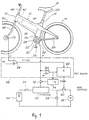
- Figure 1 shows schematically an electric motored bicycle as a preferred embodiment of a vehicle having a muscle-operated driving system and an electrical power driving system in parallel thereto.
- Fig.1 is a conceptional illustration of an embodiment of this invention
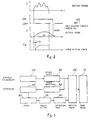
- Fig.2 is its function describing diagram
- Fig.3 is its power system diagram.
- the reference numeal 10 denotes a main frame extended from the head tube 12 aslant downward and rearward to reach the wheel shaft of the rear wheel 14. Near the middle of the main frame 10 is secured a seat tube 16. On the upper and lower portions of the seat tube 16 are installed a seat post 20 holding a saddle 18 and a bottom bracket 22, respectively.
- the bottom bracket 22 is connected with the rear end of the main frame 10 through a pair of left and right rear stays 24.
- the right side rear stay (not shown) has a driving shaft 26 (Fig.3) inserted in it. and the rotation of the crankshaft 28 held by the bottom bracket 22 is transmitted to the rear wheel 14 through a oneway clutch 30 (Fig.3) and the driving shaft 26. That is, a shaft-drive type muscle operated rear wheel driving system is constructed.
- cranks 32 On both ends of the crankshaft 28 are fastened cranks 32 on each of which is mounted a foot pedal 34.
- a cylindrical motor case 16a in which is accommodated an electric motor 36.
- the motor 36 is constituted of a brushless DC motor having, for example, a permanent magnet type rotor, the rotating shaft of this rotor is laid generally in parallel with the seat tube 16. The rotation of this rotor is transmitted to the drive shaft 26 and then to the rear wheel 14 through a oneway clutch 38 (Fig.3) and a reduction gearing 40 employing a planetary gear mechanism or the like. Consequently, a driving system operated by a muscular force inputted from the crankshaft 28 and another driving system operated by the motor 36 are provided in parallel to each other.
- the numerals 42 and 44 denote a controller and a chargeable battery, respectively, and these members are accommodated in the main frame 10.
- the numeral 46 denotes a front fork rotatably held by the head pipe 12, 48 denotes a steering handle bar, and 50 denotes a front wheel mounted on the front fork 46.
- the driving force of the motor 36 is controlled according to the muscular driving force, that is, by the treading force on the pedal 34.
- the driving systems can be of such a structure in which the driving torque T is detected by a torque detector 52 (Fig.3) having a structure for detecting the driving reaction force from in the planetary gear mechanism employed in the muscle operated driving system, and the controller 42 increases or decreases the current into the motor 36 according to the increase or decrease of this driving torque T.
- the numerals 54 and 56 denote a main switch connected between the battery 44 and the controller 42 and a flywheel diode, respectively.
- This diode 56 is employed to provide a flow path for the electric current (flywheel current) which continues to flow because of the inductance component of the motor 36 in case the controller 42 intercepted the motor current supplied from the battery 44.
- the switch 60 has a normally opened contact connected in the closed motor circuit composed of the motor 36 and the diode 56.
- the reverse control circuit 62 is provided with a driving torque comparator 64, a self-holding circuit 66 and a bicycle speed comparator 68.
- the comparator 64 judged that the output (driving torque) T of the torque detector 52 for detecting the treading force is applied, in other word, that T>0, it outputs an ON signal to the self holding circuit 66.
- the comparator 68 When the bicycle speed V detected by the bicycle speed sensor 70 installed on the front wheel 50 becomes lower than a set value V0 (for example, lower than about 1 km/h), the comparator 68 resets the self holding circuit 66 and, therefore, the switch 60 is opened.
- This self holding circuit 66 gives the ON signal of the driving torque comparator 64 priority over the reset signal of the bicycle speed comparator 68, and closes the switch 60 when the pedal 38 is treaded even in the state of the bicycle speed V lower than V0 Therefore, this switch 60 is left opened while the bicycle is at rest and is being reversed, and, after the pedal 34 is treaded, is kept closed until the bicycle speed V becomes lower than V0
- the controller 42 in this embodiment functions to start supplying a motor current with a delay of a definite time to after the switch 60 is closed. That is, while a driving torque T is inputted in the controller 42 through the normally opened contact 72, this contact 72 is closed by the output of a timer 74.
- the timer 74 closes the contact 72 with a delay of time to (about 0.1 ⁇ 0.2 sec) after the ON signal of the comparator 64. Therefore, the driving force T M of the motor 36 is generated with a delay of the time t o after the switch 60 is closed (See Fig.2).
- the switch 60 is left opened.
- a reverse voltage having a polarity shown in Fig.1 is generated by the motor 36, no short-circuit current flows because no closed circuit is formed. That is, no braking force is generated, and the bicycle can be easily pushed backward.
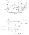
- Fig. 4 is a conceptional illustration of another embodiment, and Fig.5 is its function describing diagram.
- the reverse control circuit 62A of this embodiment has a structure in which, while the main switch 54 is opened/closed by a key switch 80, the switch 60 for reverse brake releasing is opened by a current flowing through this key switch 80 and a normally closed contact 82, and this normally closed contact 82 is opened by the output of a comparator 84 for detecting the reverse rotation of the motor 36.
- the motor 36 to be used in this invention is not limited to that employing a permanent magnet type stator, but is only required to be a DC motor having a characteristic that the polarity of the reverse voltage generated when rotated reversely is reverse to that of the voltage generated when rotated normally, as is the case with a motor employing a permanent magnet type rotor.
- control method of the controller 42 can be employed as the control method of the controller 42.
- this invention can be applied not only to bicycles but also to cycles having three or more wheels. This invention can be applied to cycles having its motor and driving wheel directly connected with each other with no oneway clutch provided therebetween.
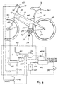
- the bicycle comprises a push-walking judging means 60 for judging the push-walking state, that is, the state of walking along pushing the bicycle by hand.
- This means 60 judges that the bicycle is in the push-walking state when following three conditions are satisfied:
- the condition 1 is judged by comparing the driving torque T with 0 by a comparator 62.
- the condition 2 is judged by comparing the forward bicyle speed V detected by a speed sensor 64 (Fig.6) installed on the front wheel 50 (or by a speed sensor installed on the rear wheel 14) with a definite speed V0 (desirably about 1 ⁇ 2 km/h) set by a setter 66 by a comparator 68.
- the condition 3 is judged by a grip switch 70 installed at least on one of the grips of the handle bar 48.
- the related comparators or the switch When these conditions are satisfied, the related comparators or the switch outputs ON signals respectively, and, when three ON signals are all present, the AND circuit 72 judges that the bicycle is in the push-walking state and outputs an ON signal.
- this embodiment is provided with a cancelling switch 74 which, even while in the push-walking state, cancels this state when the bicycle is braked, and the normally closed contact 74A connected between the electric power source and the input terminal of the AND circuit 72 is opened/closed by this switch 74. That is, this switch 74 opens the normally closed contact 74A when the bicycle is braked and turns the signal to be sent to the AND circuit 72 off. By this off signal, the AND circuit 72 turns the output signal showing the push-walking state off regardless of other conditions 1, 2 and 3.
- the output signal of this AND circuit 72 is inputted to the controller 42A for push-walking.
- This controller 42A controls the bicycle speed to a value V1 (about 2 ⁇ 3 km/h) which is a little slower than the ordinary walking speed. For example, it controls the motor current to control the motor driving force T M using the signal outputted by the speed sensor 64 to represent the bicycle speed V so that the bicycle speed V may come to this definite value V1.
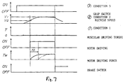
- the controller 42A makes the bicycle run by itself with its speed V kept at a definite value V1 if any one of these conditions 1, 2 and 3 is not satisfied or if the bicycle is braked, the motor operated driving is turned off and the bicycle speed V drops (See Fig. 7).
- the push-walking judging means 60 for this invention can be of various types.
- the embodiment shown in Fig. 6 may be provided with a timer 68A for retarding the ON signal of the comparator 68 so that the condition 2 may be satisfied a definite time to later after the speed V came to the definite value V0.
- the imaginary line in Fig.2 shows the action for this case.
- a switch 76 or 76A is installed on the handle bar 48 or on the saddle 18 or the like to be manually operated when going up a slope pushing the bicycle by hand, so that the push-walking controller 42A nay be actuated to keep the bicycle speed at a definite value V1 only while the switch 76 or 76A is closed.
- Fig.8 is a conceptional illustration of another embodiment and Fig.9 is its function describing diagram.
- a condition 4 of bicycle inclination angle ⁇ detection is employed instead of the condition 3 of the grip switch 70. That is, an inclination angle sensor 80 is provided on the bicycle, and it is judged that the bicycle is going up a slope when the detected inclination angle ⁇ is larger than a definite value ⁇ o .
- the numeral 82 denotes a setter for the inclination ⁇ o
- 84 denotes a comparator. Since other members are the same as those in Fig.6, their descriptions are not repeated.
- a normally closed contact 74A (Fig.6) which is opened by the brake may be provided.
- controller 42A in the embodiments above controls the bicycle speed V to a definite value V1
- it may be constructed to control the motor voltage to a definite low value to drive the motor at a low speed, or it may be a control system of other type.
- the motor 36 employed in this invention may be other than the permanent magnet type DC motor above, and may be, for example, a series-wound DC motor or the like.
- a chopper type one can be employed which changes the time ratio (duty ratio) of the ON and OFF of the DC voltage according to the torque T.
- the numeral 54 denotes a main key switch connected between the battery 44 and the controller 42.
Landscapes
- Engineering & Computer Science (AREA)
- Chemical & Material Sciences (AREA)
- Combustion & Propulsion (AREA)
- Transportation (AREA)
- Mechanical Engineering (AREA)
- Power Engineering (AREA)
- Electric Propulsion And Braking For Vehicles (AREA)
- Automatic Cycles, And Cycles In General (AREA)
Abstract
Description
- The present invention relates to a muscle-operated vehicle, specifically a bicycle having a muscle-operated driving system and an auxiliary electrical power driving system and a control means for controlling the output of the electrical power driving system. More specifically, the present invention relates to an electric-motored bicycle wherein the output of a DC electric motor is controlled according to a detected driving force of the muscle-operated driving system. Especially, the present invention relates to a muscle-operated vehicle specifically bicycle, wherein the electrical power driving system assists a manual pushing advancing movement of the bicycle when pushed by a person walking or to prevent additional electrical braking force from being generated under a rearward pushing movement of the bicycle by a person walking.
- A bicycle is well-known which, in parallel to each other is provided with a muscle-operated driving system for advancing the bicycle by treading upon the foot pedals and with an electrical motor operated driving system wherein it is possible to advance the bicycle through joint operation of both driving systems. Usually the output of the DC motor used in the electrical power driving system is ON-OFF controlled via a manual switch provided at the handle bar or is continuously controlled via a manual accelerator switch. Moreover, a system is well-known which detects the magnitude of the treading force inputted from the foot pedal and varies the driving force of the DC motor according to the increase or decrease of this treading force (Japanese unexamined patent publication (Hei 2-74491). I.e. the driving force of the electrical motor is controlled in correspondence to the increase or decrease of the detected muscular driving force which is detected from the input from the foot pedal and, when the muscular load is heavy, the driving force of the electric motor is increased to reduce the muscular load. For such types of bicycles, it is desirable that the driving systems be constructed such that the driving force of one driving system will not affect the other parallel driving system but be transmitted only to the drive wheel, usually the rear wheel of the vehicle. Therefore, it has been conceived to instal a one-way clutch in each of the muscle-operated and electrically powered driving systems as is indicated in Japanese unexamined patent application Sho 57-74285.
- However, in this case the one-way clutches will be engaged also under operating conditions wherein the bicycle is pushed by walking of the operator. In that case, the one-way clutches will also be engaged when the bicycle is reversed by pushing it back manually and the DC motor and the crank pedals will be rotated backwardly. In such a case, the electrical motor functions as a generator when rotated in its reverse direction of rotation generating a large short-circuit current and causing a great braking force.
- For example, when a permanent magnet type DC motor using a permanent magnet as a rotor or stator is rotated reversely, a reverse electrical voltage is generated with a polarity reverse to that of the voltage generated when rotated normally. Normally, in parallel to the motor coil, a fly-wheel diode is connected enabling the flow of an electric current caused by the inductance component while the motor current is intercepted. Thus, then a reverse electric voltage is generated by the reverse rotation of the motor, a large reverse current will make flow through the diode as a short-circuit current by this reverse electric voltage. Therefore, a great braking force will be generated and a great resistance force will be added when reversing the bicycle. This renders the handling of the bicycle inconvenient.
- On the other hand, as the auxiliary electrical power driving system is frequently used and controlled to be only supplementary to the driving force generated by the cyclist, the electrical power driving system affects the handling of the bicycle when same is pushed manually by a person walking along, together with the bicycle pushing same. In this case, while walking along pushing the bicycle by hand, no driving force is normally generated by the DC motor as no treading force is generated from the pedal. On the other hand, as the bicycle is equipped with a battery and the DC motor (and some other drive means such as the one-way clutches), it becomes heavier than a conventional bicycle which renders a push-walking of the bicycle cumbersome.
- Moreover, as the output of the electrical power driving system is normally only supplementary, there is no power assistance from said electrical driving system upon push-walking the bicycle e.g. when going up a steep slope when the rider must get off, pushing the bicycle by hand. Also in this case, as the bicycle is relatively heavy, considerable effort is required for walking while pushing the bicycle by hand.
- In view of the drawbacks of the above mentioned conventional systems, it is an objective of the present invention to facilitate the handling of a vehicle of the type as indicated above, having a muscle-operated driving system and an electrical power driving system specifically, under conditions of manually moving the vehicle specifically bicycle, pushing it forward or reversing it by hand.
- In order to perform said objective, the present invention comprises a muscle-operated vehicle as indicated above wherein a vehicle driving condition detecting means is provided to detect an unpowered manual vehicle advancing or reversing push-walking drive movement. Said vehicle driving condition detecting means actuates the electrical power driving system to power assist the advancing push-walking movement and/or to prevent a short-circuit braking force from being generated through the electrical power driving system upon moving the vehicle manually backwards.
- According to a preferred embodiment of the present invention, a push-walking detecting means is provided for detecting the condition of operating the vehicle by walking, pushing same (especially bicycle) by hand, said push-walking detecting means controlling a DC motor of the electrical power driving system to a certain push-walking speed which is slightly slower than the walking speed of the person pushing the vehicle.
- In this way, it becomes possible to push the bicycle with only a light muscular force utilizing the electrical power driving system specifically, the electric motor as a supplementary source of energy when walking along pushing the bicycle by hand. Thus, even when walking up a slope pushing a bicycle by hand, walking becomes very easy.
- According to yet another preferred embodiment of the present invention, the closed motor circuit comprises a brake releasing switch connected between the electric motor and a reverse connection of a diode connected in parallel to said electric motor and a reverse control circuit is provided for closing and opening said brake releasing switch when the bicycle is manually advanced or reversed, respectively. This embodiment is advantageous in that the electric motored bicycle which has a muscle-operated driving system and an electric motor-operated driving system provided in parallel to each other wherein the electric motor generates when rotated reversely, a reverse voltage having a reverse polarity in comparison to that when rotated normally, enabling the brake releasing switch to be opened when the bicycle is pushed backwards preventing a large short-circuit brake force from being generated due to the provision of a diode in parallel to the electric motor. Thus, manual handling of the bicycle is facilitated.
- Other preferred embodiments of the present invention are laid out in the further sub-claims.
- In the following, the present invention is explained in greater detail by a means of two embodiments thereof in conjunction with the associated drawings wherein:
- Figure 1 is a conceptional illustration of a bicycle according to a first embodiment of the present invention,
- Figure 2 is a diagram describing the functions of the embodiment as shown in Figure 1,
- Figure 3 is a block diagram of the muscle-operated and electrical power driving systems of the embodiment of Figures 1 and 2,
- Figure 4 is a conceptional illustration of another embodiment of the present invention performing the same purposes as the first embodiment of Figure 1,
- Figure 5 is a diagram describing the functions of the second embodiment according to Figure 4,
- Figure 6 is a conceptional illustration of a third embodiment of the present invention,
- Figure 7 is a diagram describing the function of the third embodiment of Figure 6,
- Figure 8 is a conceptional illustration of another embodiment performing the same objectives as the third embodiment of Figure 6 of the present invention,
- Figure 9 is a diagram describing the function of said fourth embodiment of Figure 8.
- Figure 1 shows schematically an electric motored bicycle as a preferred embodiment of a vehicle having a muscle-operated driving system and an electrical power driving system in parallel thereto.
- Fig.1 is a conceptional illustration of an embodiment of this invention, Fig.2 is its function describing diagram and Fig.3 is its power system diagram.
- In Fig.1, the
reference numeal 10 denotes a main frame extended from thehead tube 12 aslant downward and rearward to reach the wheel shaft of therear wheel 14. Near the middle of themain frame 10 is secured aseat tube 16. On the upper and lower portions of theseat tube 16 are installed aseat post 20 holding asaddle 18 and abottom bracket 22, respectively. - The
bottom bracket 22 is connected with the rear end of themain frame 10 through a pair of left and rightrear stays 24. The right side rear stay (not shown) has a driving shaft 26 (Fig.3) inserted in it. and the rotation of thecrankshaft 28 held by thebottom bracket 22 is transmitted to therear wheel 14 through a oneway clutch 30 (Fig.3) and thedriving shaft 26. That is, a shaft-drive type muscle operated rear wheel driving system is constructed. - On both ends of the
crankshaft 28 are fastenedcranks 32 on each of which is mounted afoot pedal 34. - In the lower portion of the
seat tube 16 is formed a cylindrical motor case 16a in which is accommodated anelectric motor 36. Themotor 36 is constituted of a brushless DC motor having, for example, a permanent magnet type rotor, the rotating shaft of this rotor is laid generally in parallel with theseat tube 16. The rotation of this rotor is transmitted to thedrive shaft 26 and then to therear wheel 14 through a oneway clutch 38 (Fig.3) and a reduction gearing 40 employing a planetary gear mechanism or the like. Consequently, a driving system operated by a muscular force inputted from thecrankshaft 28 and another driving system operated by themotor 36 are provided in parallel to each other. - In Fig.1. the
numerals main frame 10. Thenumeral 46 denotes a front fork rotatably held by thehead pipe front fork 46. - The driving force of the
motor 36 is controlled according to the muscular driving force, that is, by the treading force on thepedal 34. For example, the driving systems can be of such a structure in which the driving torque T is detected by a torque detector 52 (Fig.3) having a structure for detecting the driving reaction force from in the planetary gear mechanism employed in the muscle operated driving system, and thecontroller 42 increases or decreases the current into themotor 36 according to the increase or decrease of this driving torque T. - In Fig.1, the
numerals battery 44 and thecontroller 42 and a flywheel diode, respectively. Thisdiode 56 is employed to provide a flow path for the electric current (flywheel current) which continues to flow because of the inductance component of themotor 36 in case thecontroller 42 intercepted the motor current supplied from thebattery 44. - Next are described the
brake releasing switch 60 for preventing themotor 36 from generating the braking force and thereverse control circuit 62 for opening/closing thisswitch 60. - The
switch 60 has a normally opened contact connected in the closed motor circuit composed of themotor 36 and thediode 56. Thereverse control circuit 62 is provided with a drivingtorque comparator 64, a self-holdingcircuit 66 and abicycle speed comparator 68. When thecomparator 64 judged that the output (driving torque) T of thetorque detector 52 for detecting the treading force is applied, in other word, that T>0, it outputs an ON signal to theself holding circuit 66. Theself holding circuit 66 closes theswitch 60 on the basis of this ON signal, and holds this state until it is reset. That is, this state is maintained even if the treading force becomes 0 (T=0). - When the bicycle speed V detected by the bicycle speed sensor 70 installed on the
front wheel 50 becomes lower than a set value V₀ (for example, lower than about 1 km/h), thecomparator 68 resets theself holding circuit 66 and, therefore, theswitch 60 is opened. Thisself holding circuit 66 gives the ON signal of the drivingtorque comparator 64 priority over the reset signal of thebicycle speed comparator 68, and closes theswitch 60 when thepedal 38 is treaded even in the state of the bicycle speed V lower than V₀ Therefore, thisswitch 60 is left opened while the bicycle is at rest and is being reversed, and, after thepedal 34 is treaded, is kept closed until the bicycle speed V becomes lower than V₀ - The
controller 42 in this embodiment functions to start supplying a motor current with a delay of a definite time to after theswitch 60 is closed. That is, while a driving torque T is inputted in thecontroller 42 through the normally openedcontact 72, thiscontact 72 is closed by the output of atimer 74. Thetimer 74 closes thecontact 72 with a delay of time to (about 0.1 ~ 0.2 sec) after the ON signal of thecomparator 64. Therefore, the driving force TM of themotor 36 is generated with a delay of the time to after theswitch 60 is closed (See Fig.2). - According to this embodiment, while the bicycle is at rest or being reversed, since the driving torque T caused by the
pedal 34 is zero, theswitch 60 is left opened. When being reversed, although a reverse voltage having a polarity shown in Fig.1 is generated by themotor 36, no short-circuit current flows because no closed circuit is formed. That is, no braking force is generated, and the bicycle can be easily pushed backward. - Fig. 4 is a conceptional illustration of another embodiment, and Fig.5 is its function describing diagram. The
reverse control circuit 62A of this embodiment has a structure in which, while themain switch 54 is opened/closed by akey switch 80, theswitch 60 for reverse brake releasing is opened by a current flowing through thiskey switch 80 and a normally closedcontact 82, and this normally closedcontact 82 is opened by the output of acomparator 84 for detecting the reverse rotation of themotor 36. That is, since the polarity of the reverse voltage generated by themotor 36 while being rotated reversely (while the bicycle is being reversed) becomes as shown in Fig.4 and is reverse to that of the voltage generated while being rotated normally (while the bicycle is being advanced), this polarity is detected by thecomparator 84 and the normally closedcontact 82 is opened. Consequently, theswitch 60 is opened and the short-circuit current caused by the reverse voltage of themotor 36 is prevented from flowing. - The
motor 36 to be used in this invention is not limited to that employing a permanent magnet type stator, but is only required to be a DC motor having a characteristic that the polarity of the reverse voltage generated when rotated reversely is reverse to that of the voltage generated when rotated normally, as is the case with a motor employing a permanent magnet type rotor. - Various methods such as the chopper method, voltage switching method, etc., can be employed as the control method of the
controller 42. Further, this invention can be applied not only to bicycles but also to cycles having three or more wheels. This invention can be applied to cycles having its motor and driving wheel directly connected with each other with no oneway clutch provided therebetween. - Another embodiment of the present invention intended to facilitate an advancing push-walking movement of a bicycle is explained referring to Figures 6-9, wherein Figures 8 and 9 disclose another embodiment for the same purpose.
- In as far as the same components of the bicycle are described hereinafter, same reference numerals are being used and in view of the detailed description of said components, reference is made to the above explanation of the embodiment of Figure 1. Therefore, said functional explanations are not deemed to be necessary again and, therefore, are here omitted. Rather, the following description is focussed on the particularities of said embodiments of the push-walking assisting system.
- In this case (Figure 6), the bicycle comprises a push-walking judging means 60 for judging the push-walking state, that is, the state of walking along pushing the bicycle by hand. This means 60 judges that the bicycle is in the push-walking state when following three conditions are satisfied:
- ① The muscular driving torque T is zero;
- ② The bicycle speed V is higher than a definite speed V₀ in the forward direction; and
- ③ The grip of the
handle bar 48 is gripped. - The
condition ① is judged by comparing the driving torque T with 0 by acomparator 62. - The
condition ② is judged by comparing the forward bicyle speed V detected by a speed sensor 64 (Fig.6) installed on the front wheel 50 (or by a speed sensor installed on the rear wheel 14) with a definite speed V₀ (desirably about 1~2 km/h) set by asetter 66 by acomparator 68. - The
condition ③ is judged by a grip switch 70 installed at least on one of the grips of thehandle bar 48. - When these conditions are satisfied, the related comparators or the switch outputs ON signals respectively, and, when three ON signals are all present, the AND
circuit 72 judges that the bicycle is in the push-walking state and outputs an ON signal. - In addition, this embodiment is provided with a cancelling
switch 74 which, even while in the push-walking state, cancels this state when the bicycle is braked, and the normallyclosed contact 74A connected between the electric power source and the input terminal of the ANDcircuit 72 is opened/closed by thisswitch 74. That is, thisswitch 74 opens the normallyclosed contact 74A when the bicycle is braked and turns the signal to be sent to the ANDcircuit 72 off. By this off signal, the ANDcircuit 72 turns the output signal showing the push-walking state off regardless ofother conditions - The output signal of this AND
circuit 72 is inputted to thecontroller 42A for push-walking. Thiscontroller 42A controls the bicycle speed to a value V₁ (about 2~3 km/h) which is a little slower than the ordinary walking speed. For example, it controls the motor current to control the motor driving force TM using the signal outputted by thespeed sensor 64 to represent the bicycle speed V so that the bicycle speed V may come to this definite value V₁. - Consequently, while three
conditions controller 42A makes the bicycle run by itself with its speed V kept at a definite value V₁ if any one of theseconditions - The push-walking judging means 60 for this invention can be of various types. For example, the embodiment shown in Fig. 6 may be provided with a
timer 68A for retarding the ON signal of thecomparator 68 so that thecondition ② may be satisfied a definite time to later after the speed V came to the definite value V₀. The imaginary line in Fig.2 shows the action for this case. - Further, another structure may be employed in which a
switch 76 or 76A is installed on thehandle bar 48 or on thesaddle 18 or the like to be manually operated when going up a slope pushing the bicycle by hand, so that the push-walkingcontroller 42A nay be actuated to keep the bicycle speed at a definite value V₁ only while theswitch 76 or 76A is closed. - Fig.8 is a conceptional illustration of another embodiment and Fig.9 is its function describing diagram.
- In this embodiment. a
condition ④ of bicycle inclination angle ϑ detection is employed instead of thecondition ③ of the grip switch 70. That is, aninclination angle sensor 80 is provided on the bicycle, and it is judged that the bicycle is going up a slope when the detected inclination angle ϑ is larger than a definite value ϑo. In Fig.4, the numeral 82 denotes a setter for the inclination ϑo, and 84 denotes a comparator. Since other members are the same as those in Fig.6, their descriptions are not repeated. Of course, a normallyclosed contact 74A (Fig.6) which is opened by the brake may be provided. - Although the
controller 42A in the embodiments above controls the bicycle speed V to a definite value V₁, it may be constructed to control the motor voltage to a definite low value to drive the motor at a low speed, or it may be a control system of other type. - The
motor 36 employed in this invention may be other than the permanent magnet type DC motor above, and may be, for example, a series-wound DC motor or the like. As thecontroller 42, a chopper type one can be employed which changes the time ratio (duty ratio) of the ON and OFF of the DC voltage according to the torque T. In Fig.6, the numeral 54 denotes a main key switch connected between thebattery 44 and thecontroller 42.
Claims (15)
- Muscle-operated vehicle, especially bicycle, having a muscle-operated driving system, an auxiliary electrical power driving system and a control means for controlling the output of the electrical power driving system
characterised in that
a vehicle driving condition detecting means is provided to detect an unpowered manual vehicle advancing or reversing push-walking drive movement, operating the electrical power driving system (36) to power assist the advancing push-walking movement and/or to prevent a short circuit braking force from being generated through the electrical power driving system (36) when the vehicle is manually moved rearwards - Muscle-operated vehicle as claimed in claim 1
characterised in that
the auxiliary electrical power driving system comprises a DC motor (36) generating a reverse voltage of reversed polarity when the travelling direction of the vehicle is reversed. - Muscle-operated vehicle as claimed in claim 2
characterised in that
the DC motor (36) is provided in a motor circuit comprising a battery (44), a main switch (54) and the control means (42,42a,66). - Muscle-operated vehicle as claimed in claim 3
characterised in that
the motor circuit comprises a diode (56) connected in parallel to a motor coil of the DC motor (36), said motor circuit comprising a brake release switch (60) arranged between a reverse connection of the diode (56) and the DC motor (36). - Muscle-operated vehicle as claimed in claim 4
characterised in that
said brake release switch (60) is controlled by a reverse control circuit (62,62a). - Muscle-operated vehicle as claimed in claim 5
characterised in that
said reverse control circuit (62) comprises a driving torque comparator (64), a self-holding circuit (66) and a vehicle speed comparator (68). - Muscle-operated vehicle as claimed in claims 5 or 6
characterised in that
a delay circuit is provided comprising a timer (74) connected between the driving troque comparator (64) and the self-holding circuit (66) to control a contact (72) of a line which is adapted to input the driving torque (T) to the control means (42). - Muscle-operated vehicle as claimed in claim 5
characterised in that
the reverse control circuit (62A) comprises a comparator (84) connected to the plus and minus poles of the DC motor (36) for detecting a reverse rotation of said motor (36), said comparator (84) actuates a switch (82) to open the brake release switch (60) of the motor circuit. - Muscle-operated vehicle as claimed in claim 1
characterised in that
a push-walking detecting means is provided for detecting the condition of operating the vehicle by walking, pushing said vehicle, especially bicycle, by hand, triggering the control means (42a,42) to control the DC motor (36) to a certain push-walking speed which is slower than the walking speed. - Muscle-operated vehicle as claimed in claim 9
characterised in that
the push-walking detecting means comprises a driving troque comparator (62), a vehicle speed comparator (68), a grip switch (70) and an AND circuit (72) to activate a push-walking control means (42a,42) of the motor circuit to energize the motor (36) in response to a control means activating output of the AND circuit (72). - Muscle-operated vehicle as claimed in claim 9
characterised in that
a push-walking condition cancelling switch (74) is provided, operated in response to a braking condition of the vehicle being detected. - Muscle-operated vehicle as claimed in claim 9
characterised in that
the push-walking detecting means comprises a manually operated switch (76,76a). - Muscle-operated vehicle as claimed in at least one of the preceding claims 9-12
characterised in that
the push-walking detecting means comprises a timer (68a) in order to retard a push-walking operation of the motor (36). - Muscle-operated vehicle as claimed in claim 9
characterised in that
the push-walking detecting means comprises a vehicle inclination sensor (80) to detect an uphill push-walking condition of the vehicle. - Muscle-operated vehicle as claimed in at least one of the preceding claims 1-14
characterised in that
the muscle-operated driving system and the electrical power system are provided in parallel to each other operating a driving shaft (26) of a rear wheel drive of a bicycle via one-way clutches (30,38) respectively.
Priority Applications (1)
| Application Number | Priority Date | Filing Date | Title |
|---|---|---|---|
| EP98109549A EP0869053B1 (en) | 1991-06-04 | 1992-06-04 | Muscle-operated vehicle |
Applications Claiming Priority (6)
| Application Number | Priority Date | Filing Date | Title |
|---|---|---|---|
| JP159430/91 | 1991-06-04 | ||
| JP159425/91 | 1991-06-04 | ||
| JP3159430A JP3054234B2 (en) | 1991-06-04 | 1991-06-04 | Bicycle with electric motor |
| JP15942591A JP3161543B2 (en) | 1991-06-04 | 1991-06-04 | Bicycle with electric motor |
| JP15943091 | 1991-06-04 | ||
| JP15942591 | 1991-06-04 |
Related Child Applications (1)
| Application Number | Title | Priority Date | Filing Date |
|---|---|---|---|
| EP98109549A Division EP0869053B1 (en) | 1991-06-04 | 1992-06-04 | Muscle-operated vehicle |
Publications (3)
| Publication Number | Publication Date |
|---|---|
| EP0517224A2 true EP0517224A2 (en) | 1992-12-09 |
| EP0517224A3 EP0517224A3 (en) | 1993-04-21 |
| EP0517224B1 EP0517224B1 (en) | 2001-04-25 |
Family
ID=26486240
Family Applications (2)
| Application Number | Title | Priority Date | Filing Date |
|---|---|---|---|
| EP92109478A Expired - Lifetime EP0517224B1 (en) | 1991-06-04 | 1992-06-04 | Muscle-operated vehicle |
| EP98109549A Expired - Lifetime EP0869053B1 (en) | 1991-06-04 | 1992-06-04 | Muscle-operated vehicle |
Family Applications After (1)
| Application Number | Title | Priority Date | Filing Date |
|---|---|---|---|
| EP98109549A Expired - Lifetime EP0869053B1 (en) | 1991-06-04 | 1992-06-04 | Muscle-operated vehicle |
Country Status (3)
| Country | Link |
|---|---|
| US (1) | US5226501A (en) |
| EP (2) | EP0517224B1 (en) |
| DE (2) | DE69231799T2 (en) |
Cited By (21)
| Publication number | Priority date | Publication date | Assignee | Title |
|---|---|---|---|---|
| EP0569954A1 (en) * | 1992-05-11 | 1993-11-18 | Yamaha Hatsudoki Kabushiki Kaisha | Bicycle with electric motor |
| EP0612654A1 (en) * | 1993-02-22 | 1994-08-31 | Yamaha Motor Europe N.V. | A mechanism for driving a means of transport comprising a frame |
| EP0635423A1 (en) * | 1993-07-23 | 1995-01-25 | Yamaha Hatsudoki Kabushiki Kaisha | Muscle-operated vehicle |
| EP0636538A1 (en) * | 1993-07-26 | 1995-02-01 | Yamaha Hatsudoki Kabushiki Kaisha | Electric power assisted vehicle, in particular bicycle |
| EP0636536A1 (en) * | 1993-07-26 | 1995-02-01 | Yamaha Hatsudoki Kabushiki Kaisha | Electric power assisted bicycle |
| GB2281885A (en) * | 1993-09-16 | 1995-03-22 | Sinclair Res Ltd | Drive apparatus for a cycle |
| EP0650887A2 (en) * | 1993-10-29 | 1995-05-03 | Yamaha Hatsudoki Kabushiki Kaisha | Electrically assisted pedal operated vehicle |
| EP0650888A2 (en) * | 1993-10-29 | 1995-05-03 | Yamaha Hatsudoki Kabushiki Kaisha | Electrically assisted pedal operated vehicle |
| EP0728613A2 (en) * | 1995-01-30 | 1996-08-28 | Seiko Epson Corporation | Assist device for use in electric vehicle |
| EP0738653A2 (en) * | 1995-04-17 | 1996-10-23 | Honda Giken Kogyo Kabushiki Kaisha | Electric power assisted bicycle |
| US5603388A (en) * | 1993-09-14 | 1997-02-18 | Kabushiki Kaisha Riken | Electric powered bicycle |
| EP0790174A2 (en) * | 1996-02-13 | 1997-08-20 | Yamaha Hatsudoki Kabushiki Kaisha | Muscle-operated vehicle |
| US5664636A (en) * | 1993-10-29 | 1997-09-09 | Yamaha Hatsudoki Kabushiki Kaisha | Vehicle with electric motor |
| EP0893338A1 (en) * | 1997-07-22 | 1999-01-27 | Honda Giken Kogyo Kabushiki Kaisha | Assist force control device in motor-assisted bicycle |
| US5901807A (en) * | 1997-09-18 | 1999-05-11 | Merida Industry Co., Ltd. | Electrical drive for a bicycle |
| CN1051970C (en) * | 1993-10-29 | 2000-05-03 | 雅马哈发动机株式会社 | Vehicle with electric motor |
| EP1129934A3 (en) * | 2000-03-01 | 2004-05-19 | Honda Giken Kogyo Kabushiki Kaisha | Motor-driven bicycle |
| WO2013041666A1 (en) * | 2011-09-23 | 2013-03-28 | VON LÖBBECKE, Sandra | Motor controller for an electric auxiliary drive |
| EP2423096A3 (en) * | 2010-08-26 | 2014-10-22 | Cycling Sports Group, Inc. | Bicycle |
| EP3176066A3 (en) * | 2015-12-01 | 2017-07-19 | Yamaha Hatsudoki Kabushiki Kaisha | Electrically assisted bicycle |
| CN110126965A (en) * | 2018-02-09 | 2019-08-16 | 株式会社岛野 | Human-powered vehicle control device |
Families Citing this family (45)
| Publication number | Priority date | Publication date | Assignee | Title |
|---|---|---|---|---|
| US5237263A (en) * | 1991-06-17 | 1993-08-17 | Gannon Henry M | Electric and pedal driven bicycle with solar charging |
| JP2623419B2 (en) * | 1992-09-30 | 1997-06-25 | ヤマハ発動機株式会社 | Bicycle with electric motor |
| JP3480998B2 (en) * | 1993-10-29 | 2003-12-22 | ヤマハ発動機株式会社 | Vehicle with electric motor |
| JP3231550B2 (en) * | 1994-06-11 | 2001-11-26 | 本田技研工業株式会社 | Body cover structure of electric assist bicycle |
| JP3276782B2 (en) * | 1994-08-18 | 2002-04-22 | 本田技研工業株式会社 | Electric assisted bicycle |
| US5816355A (en) * | 1995-09-05 | 1998-10-06 | Electric Bicycle Company | Power assist apparatus for a manually operated vehicle |
| US5777442A (en) * | 1996-01-29 | 1998-07-07 | Yamaha Hatsudoki Kabushiki Kaisha | Control for electric power assisted vehicle |
| US5798702A (en) * | 1996-04-18 | 1998-08-25 | Suzuki Motor Corporation | Residual battery capacity display device for electric vehicle |
| JP3306309B2 (en) * | 1996-08-28 | 2002-07-24 | 三洋電機株式会社 | Assist electric vehicle |
| JP3163046B2 (en) * | 1996-10-25 | 2001-05-08 | 三洋電機株式会社 | Man-powered vehicle with auxiliary power |
| ES2424045T3 (en) | 1999-08-31 | 2013-09-26 | Independence Technology, L.L.C. | Motor vehicle |
| US6342769B1 (en) * | 2000-11-07 | 2002-01-29 | Orville J. Birkestrand | Electronic throttle/brake control system for monitorized wheel hub |
| ITTO20010730A1 (en) * | 2001-07-24 | 2003-01-24 | Campagnolo Srl | ANGULAR SIZE TRANSDUCER. |
| US6946650B2 (en) * | 2002-03-04 | 2005-09-20 | Independence Technology, L.L.C. | Sensor |
| US6777898B2 (en) * | 2002-09-03 | 2004-08-17 | William A. Peterson | Methods and apparatus for maintaining synchronization of a polyphase motor during power interruptions |
| JP3793143B2 (en) * | 2002-11-28 | 2006-07-05 | 株式会社シマノ | Bicycle electronic control device |
| CN2605187Y (en) * | 2003-02-13 | 2004-03-03 | 苏州工业园区诺亚科技有限公司 | Portable electric cycle |
| JP4350531B2 (en) | 2004-01-08 | 2009-10-21 | 本田技研工業株式会社 | Electric vehicle |
| JP4422532B2 (en) * | 2004-04-01 | 2010-02-24 | 本田技研工業株式会社 | Bicycle simulation equipment |
| EP1879790B1 (en) * | 2005-05-13 | 2009-03-18 | Spinwood Trading & Consulting Ltd. | Vehicle |
| EP1953079A1 (en) * | 2007-01-31 | 2008-08-06 | Tecnocarbur S.r.L. | Propulsion device for manually driving electric bicycles with assisted pedal stroke |
| US20080200079A1 (en) * | 2007-02-21 | 2008-08-21 | Patrick Lee Jansen | Separated Electric Motor Assisted Propulsion for Human-Powered Watercraft |
| US8183726B2 (en) * | 2007-03-30 | 2012-05-22 | Norman Rittenhouse | Electric motor assist bicyle |
| US20130179016A1 (en) * | 2009-07-02 | 2013-07-11 | Stephen William Gale | Power Assisted Vehicles |
| US20120145469A1 (en) * | 2010-12-14 | 2012-06-14 | Gabriel Yui Lung Tong | Wheeled device with lever pedal mechanism |
| US8408349B1 (en) * | 2011-09-22 | 2013-04-02 | Faraday Bicycles, Inc. | Electric bicycle |
| JP5689849B2 (en) * | 2012-05-18 | 2015-03-25 | マイクロスペース株式会社 | Motor drive control device |
| KR101366557B1 (en) * | 2012-09-19 | 2014-02-26 | 주식회사 만도 | Apparatus for driving electric bicycle |
| KR20140038048A (en) * | 2012-09-19 | 2014-03-28 | 주식회사 만도 | Eletric bicycle and control method thereof |
| KR20140038024A (en) * | 2012-09-19 | 2014-03-28 | 주식회사 만도 | Electric bicycle |
| DE102013205829A1 (en) * | 2013-04-03 | 2014-10-09 | Bayerische Motoren Werke Aktiengesellschaft | Routing device for vehicles |
| TWI558613B (en) | 2013-05-13 | 2016-11-21 | 達方電子股份有限公司 | Method for automatic adjustment of pedelec |
| GB201311001D0 (en) * | 2013-06-20 | 2013-08-07 | Lucabella Holdings Llc | Lucabella |
| DE102013216723A1 (en) * | 2013-08-22 | 2015-02-26 | Robert Bosch Gmbh | Muscle and / or engine power operable vehicle and method of operating the vehicle |
| US8922087B1 (en) | 2013-08-26 | 2014-12-30 | Norman P Rittenhouse | High efficiency low torque ripple multi-phase permanent magnet machine |
| DE102013225481B4 (en) * | 2013-12-10 | 2020-07-09 | Brake Force One Gmbh | Method of operating a means of transportation |
| US8925668B1 (en) * | 2014-01-24 | 2015-01-06 | Marvin Mofield | Bicycle with power assisting function |
| US8876657B1 (en) | 2014-03-18 | 2014-11-04 | Fawzi Behbehani | Automatic gear bike |
| DE102014217758A1 (en) * | 2014-09-05 | 2016-03-10 | Bayerische Motoren Werke Aktiengesellschaft | Drive aid and method for providing a supporting torque |
| US9925999B2 (en) | 2015-09-29 | 2018-03-27 | Radio Flyer Inc. | Power assist wagon |
| JP6927689B2 (en) | 2016-10-31 | 2021-09-01 | 株式会社シマノ | Bicycle control device and bicycle control system including this |
| US10583852B2 (en) | 2016-11-02 | 2020-03-10 | Radio Flyer Inc. | Foldable wagon |
| USD866676S1 (en) | 2017-11-02 | 2019-11-12 | Radio Flyer Inc. | Foldable wagon |
| US11572132B2 (en) | 2018-05-07 | 2023-02-07 | Trek Bicycle Corporation | Bicycle battery assembly |
| DE102020126079A1 (en) | 2020-10-06 | 2022-06-02 | Bio-Hybrid Gmbh | Method for operating a human-powered vehicle, control device, human-powered vehicle and computer program product |
Citations (3)
| Publication number | Priority date | Publication date | Assignee | Title |
|---|---|---|---|---|
| FR2259741A1 (en) * | 1974-01-31 | 1975-08-29 | Raleigh Industries Ltd | |
| US3921741A (en) * | 1974-07-11 | 1975-11-25 | Avco Corp | Bicycle with electric motor assist |
| US4221275A (en) * | 1978-04-28 | 1980-09-09 | Pennebaker William B | Motor-assist vehicle |
Family Cites Families (14)
| Publication number | Priority date | Publication date | Assignee | Title |
|---|---|---|---|---|
| DE2403727A1 (en) * | 1974-01-26 | 1975-08-07 | Max Seyffer | Pulley drive for moped - with freewheel clutch for energy saving for handlebar mounted motor |
| US3991843A (en) * | 1974-06-28 | 1976-11-16 | The Lucas Electrical Company Limited | Cycles |
| GB1558564A (en) * | 1975-07-03 | 1980-01-03 | Lucas Industries Ltd | Electrically assisted pedal-propelled vehicles |
| GB1585055A (en) * | 1976-06-11 | 1981-02-25 | Lucas Industries Ltd | Cycles |
| FR2411302A1 (en) * | 1977-12-06 | 1979-07-06 | Auxilec | Pedal cycle with auxiliary electric motor drive - has two free wheels to enable pedals or motor to be used independently |
| DE2929505A1 (en) * | 1978-07-20 | 1980-01-31 | Yamaha Motor Co Ltd | DEVICE FOR REGULATING THE SPEED OF A CYCLING VEHICLE |
| JPS5774285A (en) | 1980-10-28 | 1982-05-10 | Sekoh Giken Kk | Driving device for motor bicycle |
| IL71233A (en) * | 1984-03-14 | 1986-11-30 | Iliya Goldenfeld | Auxiliary drive for pedal-driven road vehicles |
| DE3636286C2 (en) * | 1985-10-25 | 1996-12-12 | Honda Motor Co Ltd | Drive assembly for a motorcycle |
| JPS63232092A (en) * | 1987-03-20 | 1988-09-28 | 本田技研工業株式会社 | Retreating device for motorcycle |
| US5024113A (en) * | 1987-09-19 | 1991-06-18 | Honda Giken Kogyo Kabushiki Kaisha | Reverse drive for vehicle |
| GB8806042D0 (en) * | 1988-03-14 | 1988-04-13 | Lean G D | Proportional control system for engine assisted bicycle |
| JPH0274491A (en) | 1988-09-10 | 1990-03-14 | Matsushita Electric Works Ltd | Bicycle with motor |
| US5078227A (en) * | 1989-06-18 | 1992-01-07 | S. A. E. Akikim | Auxiliary drive for vehicles |
-
1992
- 1992-06-04 EP EP92109478A patent/EP0517224B1/en not_active Expired - Lifetime
- 1992-06-04 EP EP98109549A patent/EP0869053B1/en not_active Expired - Lifetime
- 1992-06-04 US US07/893,530 patent/US5226501A/en not_active Expired - Lifetime
- 1992-06-04 DE DE69231799T patent/DE69231799T2/en not_active Expired - Fee Related
- 1992-06-04 DE DE69233024T patent/DE69233024T2/en not_active Expired - Fee Related
Patent Citations (3)
| Publication number | Priority date | Publication date | Assignee | Title |
|---|---|---|---|---|
| FR2259741A1 (en) * | 1974-01-31 | 1975-08-29 | Raleigh Industries Ltd | |
| US3921741A (en) * | 1974-07-11 | 1975-11-25 | Avco Corp | Bicycle with electric motor assist |
| US4221275A (en) * | 1978-04-28 | 1980-09-09 | Pennebaker William B | Motor-assist vehicle |
Non-Patent Citations (1)
| Title |
|---|
| PATENT ABSTRACTS OF JAPAN vol. 14, no. 262 (M-981)6 June 1990 & JP-A-2 074 491 ( MATSUSHITA ELECTRIC WORKS LTD ) 14 March 1990 * |
Cited By (44)
| Publication number | Priority date | Publication date | Assignee | Title |
|---|---|---|---|---|
| US5370200A (en) * | 1992-05-11 | 1994-12-06 | Yamaha Hatsudoki Kabushiki Kaisha | Bicycle with electric motor |
| EP0569954A1 (en) * | 1992-05-11 | 1993-11-18 | Yamaha Hatsudoki Kabushiki Kaisha | Bicycle with electric motor |
| EP0612654A1 (en) * | 1993-02-22 | 1994-08-31 | Yamaha Motor Europe N.V. | A mechanism for driving a means of transport comprising a frame |
| US5560266A (en) * | 1993-02-22 | 1996-10-01 | Yamaha Motor Europe, N.V. | Mechanism for driving a transporting device having frame |
| US5505277A (en) * | 1993-07-23 | 1996-04-09 | Yamaha Hatsudoki Kabushiki Kaisha | Control for electric assist vehicle |
| EP0635423A1 (en) * | 1993-07-23 | 1995-01-25 | Yamaha Hatsudoki Kabushiki Kaisha | Muscle-operated vehicle |
| EP0636536A1 (en) * | 1993-07-26 | 1995-02-01 | Yamaha Hatsudoki Kabushiki Kaisha | Electric power assisted bicycle |
| US6276479B1 (en) | 1993-07-26 | 2001-08-21 | Yamaha Hatsudoki Kabushiki Kaisha | Drive arrangement for electric power assisted bicycle |
| US5570752A (en) * | 1993-07-26 | 1996-11-05 | Yamaha Hatsudoki Kabushiki Kaisha | Transmission arrangement for electric power assisted bicycle |
| EP0636538A1 (en) * | 1993-07-26 | 1995-02-01 | Yamaha Hatsudoki Kabushiki Kaisha | Electric power assisted vehicle, in particular bicycle |
| EP0636537A1 (en) * | 1993-07-26 | 1995-02-01 | Yamaha Hatsudoki Kabushiki Kaisha | Power transmission system |
| USRE37443E1 (en) * | 1993-09-14 | 2001-11-13 | Kabushiki Kaisha Riken | Electric powered bicycle |
| CN1050576C (en) * | 1993-09-14 | 2000-03-22 | 株式会社利肯 | An electric powered bicycle |
| US5603388A (en) * | 1993-09-14 | 1997-02-18 | Kabushiki Kaisha Riken | Electric powered bicycle |
| GB2281885A (en) * | 1993-09-16 | 1995-03-22 | Sinclair Res Ltd | Drive apparatus for a cycle |
| EP0650888A3 (en) * | 1993-10-29 | 1995-09-20 | Yamaha Motor Co Ltd | Electrically assisted pedal operated vehicle. |
| EP0650887A2 (en) * | 1993-10-29 | 1995-05-03 | Yamaha Hatsudoki Kabushiki Kaisha | Electrically assisted pedal operated vehicle |
| EP0650888A2 (en) * | 1993-10-29 | 1995-05-03 | Yamaha Hatsudoki Kabushiki Kaisha | Electrically assisted pedal operated vehicle |
| EP0650887A3 (en) * | 1993-10-29 | 1995-09-20 | Yamaha Motor Co Ltd | Electrically assisted pedal operated vehicle. |
| CN1103712C (en) * | 1993-10-29 | 2003-03-26 | 雅马哈发动机株式会社 | Car with motor |
| CN1051970C (en) * | 1993-10-29 | 2000-05-03 | 雅马哈发动机株式会社 | Vehicle with electric motor |
| US5664636A (en) * | 1993-10-29 | 1997-09-09 | Yamaha Hatsudoki Kabushiki Kaisha | Vehicle with electric motor |
| EP0879757A3 (en) * | 1993-10-29 | 1999-04-21 | Yamaha Hatsudoki Kabushiki Kaisha | Electrically assisted pedal operated vehicle |
| EP0879757A2 (en) | 1993-10-29 | 1998-11-25 | Yamaha Hatsudoki Kabushiki Kaisha | Electrically assisted pedal operated vehicle |
| KR100352546B1 (en) * | 1995-01-30 | 2002-12-28 | 가부시키 가이샤 도쿄 알 앤드 디 | Auxiliary Devices for Electric Vehicles |
| EP0728613A3 (en) * | 1995-01-30 | 1996-11-13 | Seiko Epson Corp | Assist device for use in electric vehicle |
| EP0728613A2 (en) * | 1995-01-30 | 1996-08-28 | Seiko Epson Corporation | Assist device for use in electric vehicle |
| EP0738653A2 (en) * | 1995-04-17 | 1996-10-23 | Honda Giken Kogyo Kabushiki Kaisha | Electric power assisted bicycle |
| CN1064910C (en) * | 1995-04-17 | 2001-04-25 | 本田技研工业株式会社 | Electric booster bicycle |
| EP0738653A3 (en) * | 1995-04-17 | 1997-07-30 | Honda Motor Co Ltd | Electric power assisted bicycle |
| EP0790174A2 (en) * | 1996-02-13 | 1997-08-20 | Yamaha Hatsudoki Kabushiki Kaisha | Muscle-operated vehicle |
| CN1071212C (en) * | 1996-02-13 | 2001-09-19 | 雅马哈发动机株式会社 | Motor control device for motor-operated vehicle |
| EP0790174A3 (en) * | 1996-02-13 | 1997-11-05 | Yamaha Hatsudoki Kabushiki Kaisha | Muscle-operated vehicle |
| EP0893338A1 (en) * | 1997-07-22 | 1999-01-27 | Honda Giken Kogyo Kabushiki Kaisha | Assist force control device in motor-assisted bicycle |
| CN1111486C (en) * | 1997-07-22 | 2003-06-18 | 本田技研工业株式会社 | Auxiliary propulsion-unit control device for use in the electrically assisted bicycle |
| US5901807A (en) * | 1997-09-18 | 1999-05-11 | Merida Industry Co., Ltd. | Electrical drive for a bicycle |
| EP1129934A3 (en) * | 2000-03-01 | 2004-05-19 | Honda Giken Kogyo Kabushiki Kaisha | Motor-driven bicycle |
| EP2423096A3 (en) * | 2010-08-26 | 2014-10-22 | Cycling Sports Group, Inc. | Bicycle |
| EP3037335A1 (en) * | 2010-08-26 | 2016-06-29 | Cycling Sports Group, Inc. | Bicycle |
| WO2013041666A1 (en) * | 2011-09-23 | 2013-03-28 | VON LÖBBECKE, Sandra | Motor controller for an electric auxiliary drive |
| EP3176066A3 (en) * | 2015-12-01 | 2017-07-19 | Yamaha Hatsudoki Kabushiki Kaisha | Electrically assisted bicycle |
| US10189541B2 (en) | 2015-12-01 | 2019-01-29 | Yamaha Hatsudoki Kabushiki Kaisha | Electrically assisted bicycle |
| CN110126965A (en) * | 2018-02-09 | 2019-08-16 | 株式会社岛野 | Human-powered vehicle control device |
| CN110126965B (en) * | 2018-02-09 | 2021-07-20 | 株式会社岛野 | Control device for human-powered vehicle |
Also Published As
| Publication number | Publication date |
|---|---|
| EP0517224A3 (en) | 1993-04-21 |
| EP0869053A2 (en) | 1998-10-07 |
| DE69233024D1 (en) | 2003-05-28 |
| DE69233024T2 (en) | 2003-10-16 |
| EP0869053A3 (en) | 1999-10-06 |
| US5226501A (en) | 1993-07-13 |
| EP0517224B1 (en) | 2001-04-25 |
| DE69231799D1 (en) | 2001-05-31 |
| DE69231799T2 (en) | 2001-08-09 |
| EP0869053B1 (en) | 2003-04-23 |
Similar Documents
| Publication | Publication Date | Title |
|---|---|---|
| EP0869053B1 (en) | Muscle-operated vehicle | |
| JP3054234B2 (en) | Bicycle with electric motor | |
| JP4118984B2 (en) | Electric assist bicycle | |
| TWI229047B (en) | Electric bicycle | |
| EP1298050B1 (en) | Indicator of a motor-assisted bicycle | |
| EP1886913B1 (en) | Electrically assisted bicycle | |
| EP0168905A2 (en) | An auxiliary drive for pedal-driven road vehicles | |
| JPH09263290A (en) | Motor-driven bicycle | |
| JP5485111B2 (en) | Saddle riding | |
| JP2003204602A (en) | Regenerative control device for electric motor vehicle | |
| JP3480998B2 (en) | Vehicle with electric motor | |
| EP0650887B1 (en) | Electrically assisted pedal operated vehicle | |
| JP2010264977A (en) | Power-assisted bicycle | |
| JP3985930B2 (en) | Auxiliary force control device for battery-assisted bicycle | |
| JPH1149063A (en) | Bicycle equipped with electric motor | |
| JP2003104277A (en) | Regenerating control unit of power-assisted bicycle | |
| JP3054399B2 (en) | Bicycle with electric motor | |
| JP3161543B2 (en) | Bicycle with electric motor | |
| JP3480997B2 (en) | Vehicle with electric motor | |
| EP0650888B1 (en) | Electrically assisted pedal operated vehicle | |
| JPH04358987A (en) | Motorbike | |
| JPH07132874A (en) | Motor-driven vehicle with pedal | |
| JP3642442B2 (en) | Electric vehicle with pedal | |
| JP3377242B2 (en) | Bicycle with electric motor | |
| JP2000085675A (en) | Motor-assisted bicycle |
Legal Events
| Date | Code | Title | Description |
|---|---|---|---|
| PUAI | Public reference made under article 153(3) epc to a published international application that has entered the european phase |
Free format text: ORIGINAL CODE: 0009012 |
|
| AK | Designated contracting states |
Kind code of ref document: A2 Designated state(s): DE FR IT |
|
| PUAL | Search report despatched |
Free format text: ORIGINAL CODE: 0009013 |
|
| AK | Designated contracting states |
Kind code of ref document: A3 Designated state(s): DE FR IT |
|
| 17P | Request for examination filed |
Effective date: 19931020 |
|
| 17Q | First examination report despatched |
Effective date: 19940706 |
|
| GRAG | Despatch of communication of intention to grant |
Free format text: ORIGINAL CODE: EPIDOS AGRA |
|
| GRAG | Despatch of communication of intention to grant |
Free format text: ORIGINAL CODE: EPIDOS AGRA |
|
| GRAH | Despatch of communication of intention to grant a patent |
Free format text: ORIGINAL CODE: EPIDOS IGRA |
|
| GRAH | Despatch of communication of intention to grant a patent |
Free format text: ORIGINAL CODE: EPIDOS IGRA |
|
| GRAA | (expected) grant |
Free format text: ORIGINAL CODE: 0009210 |
|
| AK | Designated contracting states |
Kind code of ref document: B1 Designated state(s): DE FR IT |
|
| ITF | It: translation for a ep patent filed |
Owner name: PROPRIA S.R.L. |
|
| REF | Corresponds to: |
Ref document number: 69231799 Country of ref document: DE Date of ref document: 20010531 |
|
| ET | Fr: translation filed | ||
| PLBE | No opposition filed within time limit |
Free format text: ORIGINAL CODE: 0009261 |
|
| STAA | Information on the status of an ep patent application or granted ep patent |
Free format text: STATUS: NO OPPOSITION FILED WITHIN TIME LIMIT |
|
| 26N | No opposition filed | ||
| PGFP | Annual fee paid to national office [announced via postgrant information from national office to epo] |
Ref country code: DE Payment date: 20060601 Year of fee payment: 15 |
|
| PGFP | Annual fee paid to national office [announced via postgrant information from national office to epo] |
Ref country code: FR Payment date: 20060608 Year of fee payment: 15 |
|
| PGFP | Annual fee paid to national office [announced via postgrant information from national office to epo] |
Ref country code: IT Payment date: 20070622 Year of fee payment: 16 |
|
| REG | Reference to a national code |
Ref country code: FR Ref legal event code: ST Effective date: 20080229 |
|
| PG25 | Lapsed in a contracting state [announced via postgrant information from national office to epo] |
Ref country code: DE Free format text: LAPSE BECAUSE OF NON-PAYMENT OF DUE FEES Effective date: 20080101 |
|
| PG25 | Lapsed in a contracting state [announced via postgrant information from national office to epo] |
Ref country code: FR Free format text: LAPSE BECAUSE OF NON-PAYMENT OF DUE FEES Effective date: 20070702 |
|
| PG25 | Lapsed in a contracting state [announced via postgrant information from national office to epo] |
Ref country code: IT Free format text: LAPSE BECAUSE OF NON-PAYMENT OF DUE FEES Effective date: 20080604 |