KR20140038024A - Electric bicycle - Google Patents
Electric bicycle Download PDFInfo
- Publication number
- KR20140038024A KR20140038024A KR1020120104083A KR20120104083A KR20140038024A KR 20140038024 A KR20140038024 A KR 20140038024A KR 1020120104083 A KR1020120104083 A KR 1020120104083A KR 20120104083 A KR20120104083 A KR 20120104083A KR 20140038024 A KR20140038024 A KR 20140038024A
- Authority
- KR
- South Korea
- Prior art keywords
- frame
- control unit
- electronic control
- generator
- ecu
- Prior art date
Links
- 238000000034 method Methods 0.000 claims description 5
- 239000000463 material Substances 0.000 claims description 4
- 238000004873 anchoring Methods 0.000 abstract 2
- 230000008878 coupling Effects 0.000 description 10
- 238000010168 coupling process Methods 0.000 description 10
- 238000005859 coupling reaction Methods 0.000 description 10
- 238000009434 installation Methods 0.000 description 4
- 230000017525 heat dissipation Effects 0.000 description 2
- XAGFODPZIPBFFR-UHFFFAOYSA-N aluminium Chemical compound [Al] XAGFODPZIPBFFR-UHFFFAOYSA-N 0.000 description 1
- 229910052782 aluminium Inorganic materials 0.000 description 1
- 230000002349 favourable effect Effects 0.000 description 1
- 238000010248 power generation Methods 0.000 description 1
- 239000000758 substrate Substances 0.000 description 1
Images


Classifications
-
- B—PERFORMING OPERATIONS; TRANSPORTING
- B62—LAND VEHICLES FOR TRAVELLING OTHERWISE THAN ON RAILS
- B62K—CYCLES; CYCLE FRAMES; CYCLE STEERING DEVICES; RIDER-OPERATED TERMINAL CONTROLS SPECIALLY ADAPTED FOR CYCLES; CYCLE AXLE SUSPENSIONS; CYCLE SIDE-CARS, FORECARS, OR THE LIKE
- B62K3/00—Bicycles
- B62K3/02—Frames
- B62K3/10—Frames of single-beam type, i.e. connecting steering head to rear axle
-
- B—PERFORMING OPERATIONS; TRANSPORTING
- B62—LAND VEHICLES FOR TRAVELLING OTHERWISE THAN ON RAILS
- B62K—CYCLES; CYCLE FRAMES; CYCLE STEERING DEVICES; RIDER-OPERATED TERMINAL CONTROLS SPECIALLY ADAPTED FOR CYCLES; CYCLE AXLE SUSPENSIONS; CYCLE SIDE-CARS, FORECARS, OR THE LIKE
- B62K11/00—Motorcycles, engine-assisted cycles or motor scooters with one or two wheels
- B62K11/02—Frames
- B62K11/10—Frames characterised by the engine being over or beside driven rear wheel
-
- B—PERFORMING OPERATIONS; TRANSPORTING
- B62—LAND VEHICLES FOR TRAVELLING OTHERWISE THAN ON RAILS
- B62K—CYCLES; CYCLE FRAMES; CYCLE STEERING DEVICES; RIDER-OPERATED TERMINAL CONTROLS SPECIALLY ADAPTED FOR CYCLES; CYCLE AXLE SUSPENSIONS; CYCLE SIDE-CARS, FORECARS, OR THE LIKE
- B62K11/00—Motorcycles, engine-assisted cycles or motor scooters with one or two wheels
-
- B—PERFORMING OPERATIONS; TRANSPORTING
- B60—VEHICLES IN GENERAL
- B60L—PROPULSION OF ELECTRICALLY-PROPELLED VEHICLES; SUPPLYING ELECTRIC POWER FOR AUXILIARY EQUIPMENT OF ELECTRICALLY-PROPELLED VEHICLES; ELECTRODYNAMIC BRAKE SYSTEMS FOR VEHICLES IN GENERAL; MAGNETIC SUSPENSION OR LEVITATION FOR VEHICLES; MONITORING OPERATING VARIABLES OF ELECTRICALLY-PROPELLED VEHICLES; ELECTRIC SAFETY DEVICES FOR ELECTRICALLY-PROPELLED VEHICLES
- B60L50/00—Electric propulsion with power supplied within the vehicle
- B60L50/50—Electric propulsion with power supplied within the vehicle using propulsion power supplied by batteries or fuel cells
-
- B—PERFORMING OPERATIONS; TRANSPORTING
- B62—LAND VEHICLES FOR TRAVELLING OTHERWISE THAN ON RAILS
- B62K—CYCLES; CYCLE FRAMES; CYCLE STEERING DEVICES; RIDER-OPERATED TERMINAL CONTROLS SPECIALLY ADAPTED FOR CYCLES; CYCLE AXLE SUSPENSIONS; CYCLE SIDE-CARS, FORECARS, OR THE LIKE
- B62K15/00—Collapsible or foldable cycles
- B62K15/006—Collapsible or foldable cycles the frame being foldable
-
- B—PERFORMING OPERATIONS; TRANSPORTING
- B62—LAND VEHICLES FOR TRAVELLING OTHERWISE THAN ON RAILS
- B62K—CYCLES; CYCLE FRAMES; CYCLE STEERING DEVICES; RIDER-OPERATED TERMINAL CONTROLS SPECIALLY ADAPTED FOR CYCLES; CYCLE AXLE SUSPENSIONS; CYCLE SIDE-CARS, FORECARS, OR THE LIKE
- B62K25/00—Axle suspensions
- B62K25/005—Axle suspensions characterised by the axle being supported at one end only
-
- B—PERFORMING OPERATIONS; TRANSPORTING
- B62—LAND VEHICLES FOR TRAVELLING OTHERWISE THAN ON RAILS
- B62M—RIDER PROPULSION OF WHEELED VEHICLES OR SLEDGES; POWERED PROPULSION OF SLEDGES OR SINGLE-TRACK CYCLES; TRANSMISSIONS SPECIALLY ADAPTED FOR SUCH VEHICLES
- B62M6/00—Rider propulsion of wheeled vehicles with additional source of power, e.g. combustion engine or electric motor
- B62M6/40—Rider propelled cycles with auxiliary electric motor
-
- B—PERFORMING OPERATIONS; TRANSPORTING
- B62—LAND VEHICLES FOR TRAVELLING OTHERWISE THAN ON RAILS
- B62M—RIDER PROPULSION OF WHEELED VEHICLES OR SLEDGES; POWERED PROPULSION OF SLEDGES OR SINGLE-TRACK CYCLES; TRANSMISSIONS SPECIALLY ADAPTED FOR SUCH VEHICLES
- B62M7/00—Motorcycles characterised by position of motor or engine
- B62M7/12—Motorcycles characterised by position of motor or engine with the engine beside or within the driven wheel
Landscapes
- Engineering & Computer Science (AREA)
- Mechanical Engineering (AREA)
- Chemical & Material Sciences (AREA)
- Combustion & Propulsion (AREA)
- Transportation (AREA)
- Life Sciences & Earth Sciences (AREA)
- Sustainable Development (AREA)
- Sustainable Energy (AREA)
- Power Engineering (AREA)
- Electric Propulsion And Braking For Vehicles (AREA)
- Arrangement Or Mounting Of Propulsion Units For Vehicles (AREA)
Abstract
Description
본 발명은 전기 자전거에 관한 것으로써, 특히 전자제어유닛(ECU)의 설치구조가 개선된 전기 자전거에 관한 것이다.The present invention relates to an electric bicycle, and more particularly to an electric bicycle having an improved installation structure of an electronic control unit (ECU).
근래 들어 사용편리성을 높이고 사용자의 체력소모를 줄이고자 모터를 구동력으로 주행하는 전기 자전거가 개발되고 있다.In recent years, electric bicycles have been developed to increase the usability and reduce the user's physical power consumption by driving the motor as a driving force.
이러한 전기 자전거는 뼈대를 이루는 프레임과, 프레임에 장착되는 바퀴, 페달, 손잡이 등을 구비하여 일반 자전거와 유사한 외형을 갖는다. Such an electric bicycle has a skeleton frame, a wheel mounted on the frame, a pedal, a handle, and the like, and has an appearance similar to a general bicycle.
구동력 제공을 위한 모터는 전륜이나 후륜에 설치된다. 모터는 통상 배터리를 통해 전력을 공급받게 되며, 모터 및 모터의 구동관 관련된 전기 자전거의 의 전반적인 동작은 전자제어유닛(ECU)를 통해 제어된다. The motor for providing the driving force is installed on the front wheel or the rear wheel. The motor is usually supplied with electric power through the battery, and the overall operation of the electric bicycle associated with the drive tube of the motor and the motor is controlled through an electronic control unit (ECU).
한편, 전자제어유닛(ECU)의 경우 내장된 회로기판이 외부 충격으로부터 쉽게 손상될 우려가 있는데, 이에 따라 최근에는 전자제어유닛(ECU)을 프레임에 내장되도록 설치함으로써, 프레임을 전자제어유닛(ECU)의 보호 구조물로 이용함과 동시에 전자제어유닛(ECU)으로 인해 전기 자전거의 외관이 저해되는 것을 방지하고자 하는 노력이 주목받고 있다. On the other hand, in the case of the electronic control unit (ECU), there is a possibility that the built-in circuit board is easily damaged from an external impact. Accordingly, recently, by installing the electronic control unit (ECU) And an electronic control unit (ECU) is used to prevent the appearance of the electric bicycle from being hindered.
그러나 이때는 프레임에 내장되는 전자제어유닛(ECU)의 유동을 방지하기 위해 좁은 프레임 내부공간에 별도의 고정용 브래킷 등을 설치해야 하기 때문에, 프레임 내부 전자제어유닛(ECU)의 설치구조가 복잡해지는 문제점이 있었다.However, in this case, in order to prevent the flow of the electronic control unit (ECU) built in the frame, a separate fixing bracket or the like must be installed in a narrow internal space of the frame so that the installation structure of the electronic control unit .
본 발명의 실시예는 프레임에 내장되는 전자제어유닛(ECU)을 효과적으로 보호할 수 있도록 하면서도 전자제어유닛(ECU)의 설치구조가 간소화된 전기 자전거를 제공하고자 한다.An embodiment of the present invention is intended to provide an electric bicycle in which the electronic control unit (ECU) built in the frame is effectively protected while the installation structure of the electronic control unit (ECU) is simplified.
본 발명의 일 측면에 따르면, 전기 자전거는 전륜 또는 후륜을 회전시키는 모터, 상기 모터에 전력을 공급하는 배터리, 상기 전륜과 후륜 사이의 프레임에 페달이 연결되도록 설치되어 상기 페달의 회전력을 전기에너지로 변화시켜 상기 배터리로 공급하는 발전기, 상기 발전기 상부에 직접 고정된 상태로 상기 프레임에 내장된 전자제어유닛(ECU)을 포함하도록 구성될 수 있다. According to an aspect of the present invention, there is provided an electric bicycle comprising: a motor for rotating a front wheel or a rear wheel; a battery for supplying electric power to the motor; a pedal connected to a frame between the front wheel and the rear wheel, And an electronic control unit (ECU) embedded in the frame directly fixed to the upper portion of the generator.
상기 프레임은 상기 전륜이 마련되는 프론트 프레임과, 상기 후륜이 마련되는 리어 프레임과, 중공으로 형성되어 일단은 상기 프론트 프레임과 리어 프레임 사이에 연결되고 타단 안쪽으로 상기 발전기가 설치되는 센터 프레임을 더 포함하고, 상기 전자제어유닛(ECU)은 상기 센터 프레임 양단 사이에 내장되도록 구성될 수 있다. The frame further includes a front frame having the front wheels, a rear frame having the rear wheels, and a center frame having one end connected to the front frame and the rear frame and having the generator installed inside the other end , And the electronic control unit (ECU) can be configured to be embedded between both ends of the center frame.
상기 발전기 상부에는 상기 전자제어유닛(ECU)의 고정을 위한 장착부가 상부로 돌출되도록 마련되고, 상기 장착부 위치에 대응하는 상기 센터 프레임의 내벽은 상기 장착부의 유동이 방지되도록 상기 장착부 외면에 밀착되도록 구성될 수 있다. Wherein a mounting portion for fixing the electronic control unit (ECU) is provided on an upper portion of the generator, and an inner wall of the center frame corresponding to the position of the mounting portion is in close contact with an outer surface of the mounting portion, .
상기 발전기 상부에는 상기 전자제어유닛(ECU)의 고정을 위한 장착부가 상부로 돌출되도록 마련되고, 상기 전자제어유닛(ECU)는 회로기판과, 상기 회로기판이 내장된 하우징을 포함하며, 상기 회로기판은 상기 하우징 한쪽 측판 내면에 장착되고, 상기 하우징은 바닥판을 통해 상기 장착부에 고정되며, 상기 회로기판이 장착된 상기 하우징의 측판 및 바닥판은 동일한 방열소재로 마련될 수 있다. Wherein a mounting portion for fixing the electronic control unit (ECU) is provided on an upper portion of the generator, and the electronic control unit (ECU) includes a circuit board and a housing in which the circuit board is embedded, The housing is fixed to the mounting portion through a bottom plate, and the side plate and the bottom plate of the housing on which the circuit board is mounted may be provided with the same heat radiating material.
상기 프론트 프레임과 리어 프레임이 상기 센터프레임의 좌우 양측으로 접힐 수 있도록 상기 프론트 프레임의 후단과 상기 리어 프레임의 선단은 상기 센터 프레임의 상단 양측에 각각 회전 가능하게 결합되도록 구성될 수 있다. The rear end of the front frame and the front end of the rear frame may be rotatably coupled to both upper ends of the center frame so that the front frame and the rear frame may be folded to both sides of the center frame.
또한 본 발명의 다른 일 측면에 따르면, 전기 자전거는 전륜 또는 후륜을 회전시키는 모터, 상기 모터에 전력을 공급하는 배터리, 페달이 연결되도록 설치되어 상기 페달의 회전력을 전기에너지로 변화시켜 상기 배터리로 공급하는 발전유닛과, 상기 발전유닛을 감싸는 커버를 구비하여 상기 전륜과 후륜 사이에 마련된 발전기, 상기 전자제어유닛(ECU)이 상기 발전기 상부에 직접 고정되도록 상기 커버 상부에 일체로 마련된 장착부를 포함할 수 있다. According to another aspect of the present invention, there is provided an electric bicycle comprising a motor for rotating a front wheel or a rear wheel, a battery for supplying electric power to the motor, and a pedal connected to the electric motor so as to convert rotational force of the pedal into electric energy, A generator disposed between the front wheel and the rear wheel, and a mounting portion integrally formed on the upper portion of the cover so that the electronic control unit (ECU) is directly fixed to the upper portion of the generator. have.
본 발명의 실시 예에 따른 전기 자전거는 전자제어유닛(ECU)이 전륜가 후륜 사이에 배치되는 발전기 직상부에 직결된 상태로 프레임에 내장된다. The electric bicycle according to the embodiment of the present invention is embedded in the frame with the electronic control unit (ECU) directly connected to the upper portion of the generator disposed between the front wheel and the rear wheel.
따라서 이와 같은 전기 자전거는 전자제어유닛(ECU)을 별도의 고정 구조물을 사용하지 않고서도 프레임 내부에 안정적으로 고정시킬 수 있게 되므로, 전자제어유닛의 설치구조가 간소화되면서도 전자제어유닛을 효과적으로 보호할 수 있게 된다.Therefore, such an electric bicycle can stably fix the electronic control unit (ECU) inside the frame without using a separate fixing structure, so that the electronic control unit can be effectively protected .
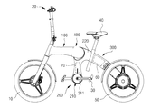
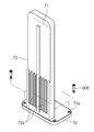
도 1은 본 발명의 실시 예에 따른 전기 자전거의 사시도이다.
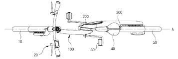
도 2는 본 발명의 실시 예에 따른 전기 자전거의 평면도이다.
도 3은 본 발명의 실시 예에 따른 전기 자전거의 측면도이다.
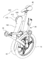
도 4는 본 발명의 실시 예에 따른 전기 자전거가 접힌 상태의 사시도이다.
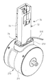
도 5는 본 발명의 실시 예에 따른 전기 자전거에 있어서 발전기 및 발전기에 고정된 전자제어유닛의 구조를 도시한 사시도이다.
도 6은 도 5의 상태에서 전자제어유닛이 발전기로부터 분리된 상태를 도시한 사시도이다.
도 7은 본 발명의 실시 예에 따른 전기 자전거의 전자제어유닛에서 상호 일체로 구성된 하우징의 측판과 바닥판의 구조를 도시한 사시도이다.
도 8은 본 발명의 실시예에 따른 전기 자전거의 센터 프레임의 하부 쪽 요부 단면도이다. 1 is a perspective view of an electric bicycle according to an embodiment of the present invention.
2 is a plan view of an electric bicycle according to an embodiment of the present invention.
3 is a side view of an electric bicycle according to an embodiment of the present invention.
4 is a perspective view of an electric bicycle according to an embodiment of the present invention in a folded state.
5 is a perspective view showing a structure of an electronic control unit fixed to a generator and a generator in an electric bicycle according to an embodiment of the present invention.
6 is a perspective view showing a state in which the electronic control unit is separated from the generator in the state of Fig. 5;
7 is a perspective view showing a structure of a side plate and a bottom plate of a housing integrally formed in an electronic control unit of an electric bicycle according to an embodiment of the present invention.
8 is a cross-sectional view of a lower portion of a center frame of an electric bicycle according to an embodiment of the present invention.
이하에서는 본 발명의 실시 예들을 첨부 도면을 참조하여 상세히 설명한다. 이하에 소개되는 실시 예들은 본 발명이 속하는 기술분야에서 통상의 지식을 가진 자에게 본 발명의 사상이 충분히 전달될 수 있도록 하기 위해 예로서 제공되는 것이다. 본 발명은 이하 설명되는 실시 예들에 한정되지 않고 다른 형태로 구체화될 수도 있다. 본 발명을 명확하게 설명하기 위하여 설명과 관계없는 부분은 도면에서 생략하였으며 도면들에 있어서, 구성요소의 폭, 길이, 두께 등은 편의를 위하여 과장되어 표현될 수 있다. 명세서 전체에 걸쳐서 동일한 참조번호들은 동일한 구성요소들을 나타낸다.Hereinafter, embodiments of the present invention will be described in detail with reference to the accompanying drawings. The embodiments described below are provided by way of example so that those skilled in the art will be able to fully understand the spirit of the present invention. The present invention is not limited to the embodiments described below, but may be embodied in other forms. In order to clearly explain the present invention, parts not related to the description are omitted from the drawings, and the width, length, thickness, etc. of the components may be exaggerated for convenience. Like reference numerals designate like elements throughout the specification.
도 1은 본 발명의 일 실시 예에 따른 전기 자전거를 도시한 사시도이며, 도 2는 도 1의 평면도이며, 도 3은 도 1의 측면도이다. 그리고 도 4는 접혀진 상태의 전기 자전거의 사시도이다.FIG. 1 is a perspective view showing an electric bicycle according to an embodiment of the present invention, FIG. 2 is a plan view of FIG. 1, and FIG. 3 is a side view of FIG. 4 is a perspective view of the folded electric bicycle.
도 1 내지 도 4를 참조하면, 본 발명의 일 실시 예에 따른 전기 자전거는 프레임(100,200,300)을 통해 뼈대를 이루며, 프레임(100,200,300)은 전륜(10) 및 핸들부(20)가 마련되는 프론트 프레임(100)과, 후륜(50)이 마련되는 리어 프레임(300)과, 페달(30) 및 안장(40)이 마련되도록 프론트 프레임(100)과 리어 프레임(300) 사이에 위치되는 센터 프레임(200)을 포함한다. 1 to 4, an electric bicycle according to an embodiment of the present invention comprises a
보관이나 운반시 전기 자전거의 크기를 줄일 수 있도록 각 프레임(100,200,300)은 힌지결합부(400)를 중심으로 서로 회동 가능하게 결합된다.In order to reduce the size of the electric bicycle when storing or transporting, each
프론트 프레임(100)은 내부 공간을 가지며 바 형태로 마련되어 일단에는 핸들튜브(110)가 마련되고, 타단에는 센터 프레임(200)이 회전 가능하게 결합된다. 핸들튜브(110)는 중공 형태로 마련되어 핸들스템(21)이 회전 가능하게 결합된다. 핸들스템(21)은 핸들튜브(110) 하측으로 전륜고정프레임(22)을 구비하고, 상측으로 핸들고정프레임(23)을 구비한다. 전륜고정프레임(22)은 전륜(10)과 후륜(50)이 동일선(도 2의 A 참조) 상에 위치할 수 있도록 핸들스템(21)을 중심으로부터 측면으로 일부 밴딩하여 마련된다. 핸들고정프레임(23)은 바 형태의 핸들(24) 중심을 지지하며, 핸들(24)의 양 끝단에는 그립(25)과, 전륜(10) 및 후륜(50)의 제동을 위한 브레이크 레버(26)가 각각 마련된다. 핸들(24)의 일측에는 전기 자전거의 변속, 배터리 등의 정보를 표시하는 디스플레이장치(27)가 착탈 가능하게 설치되며, 타측에는 모터의 온/오프와 변속을 위한 레버(28)가 설치된다.The
센터 프레임(200)은 중공의 내부 공간을 가지며 바 형태로 마련된다. 센터 프레임(200) 상단 양측에는 프론트 프레임(100)의 후단과 리어 프레임(300)의 선단이 회전 가능하게 결합된다. 이에 따라 프론트 프레임(100)과 리어 프레임(300)은 센터 프레임(200)의 좌우 양측으로 위치되도록 접힐 수 있게 된다. The
센터 프레임(200)의 하단에는 발전기(210)가 설치되며, 발전기(210) 양측으로는 한 쌍의 페달(30)이 연결 된다. 발전기(210)는 페달(30)의 회전력을 전기에너지로 변화시키고, 이러한 전기에너지는 배터리(60)로 공급되어 축전된다. 발전기(210)는 발전작용을 수행하는 내부의 발전유닛(미도시)을 외부에서 커버(211)가 감싸는 형태로 마련된다. A
또한, 센터 프레임(200)은 안장(40)를 설치할 수 있도록 새들 프레임(220)을 포함할 수 있다. 새들 프레임(220)은 안장(40)을 설치할 수 있는 안장튜브(42)를 후방에 구비하며, 안장튜브(42)에는 안장(40)의 높이를 조절할 수 있는 새들봉(52)이 결합된다.In addition, the
리어 프레임(300)은 내부 공간을 가지며 바 형태로 마련되어 일단에는 후륜(50)이 회전 가능하게 설치되고, 타단에는 센터 프레임(200)이 회전 가능하게 설치된다.The
리어 프레임(300)의 내부 공간에는 상기 배터리(60)와, 배터리 관리 시스템(Battery Management System)(미도시) 등이 마련된다. In the inner space of the
후륜(50)에는 모터(52)가 설치된다. 모터(52)는 배터리(60)로부터 전력을 공급받아 후륜(50)을 회전시킴으로써 전기 자전거에 구동력을 제공하게 된다. The
또 전륜 및 후륜(10,50)에는 상기 브레이크레버(26)의 동작 시 회전력이 제한을 위한 제동부재로서 디스크(14,54) 및 마찰 패드가 장착된다. The front and
따라서 이와 같이 구성된 전기자전거는 사용자가 레버(28)를 조작하여 모터(52)를 구동시킴에 따라 후륜(50)이 회전하면서 주행이 가능하게 상태가 된다. 이때 발로 페달(30)을 회전시키면, 페달(30)의 회전력은 발전기(210)에서 전기에너지로 변환되고, 변환된 전기에너지는 배터리(60)에 축전되어 배터리(60)의 지속적인 사용이 가능하도록 한다. 물론 배터리(60)는 발전기(210)를 통하지 않은 상태에서도 충전기를 통해 충전이 가능하다. Thus, the electric bicycle configured as described above is in a state in which the
그리고 프레임(100,200,300)의 접철동작을 위해 상기 힌지결합부(400)는 프론트 프레임(100)의 단부에 마련되는 프론트 힌지결합부(410)와, 리어 프레임(300)의 단부에 마련되는 리어 힌지결합부(430)와, 센터 프레임(200)의 단부에 마련되는 센터 힌지결합부(420)를 포함한다. 프론트 힌지결합부(410)와 리어 힌지결합부(430)는 센터 힌지결합부(420)의 좌우 측면에 결합된다. The
각 힌지결합부(410,420,430)는 전륜(10)과 후륜(50)이 형성하는 직선(A)에 대해 약 6도 정도의 경사각(θ)을 갖는다. 이는 자전거가 펼쳐진 상태에서는 전륜(10)과 후륜(50)이 동일선 상에 위치하도록 하며, 접철된 상태에서는 전륜(10)과 후륜(50)이 나란하게 병렬로 위치하도록 하기 위함이다. 프레임(100,200,300) 사이가 접힌 상태에서 프론트 프레임(100)과 리어 프레임(300)은 센터 프레임(420)의 좌우 양측으로 위치된다. 펼쳐진 상태에서 프레임(100,200,300)의 접철 동작을 차단 또는 허용하도록 힌지결합부(400) 일측으로는 작동레버가 설치될 수 있다. Each of the
따라서 사용자는 힌지결합부(400)를 중심으로 프론트 프레임(100)과 리어 프레임(300)을 센터 프레임(200) 양측에 위치되도록 프레임(100,200,300)을 접을 수 있게 되어 운반이나 보관시 전기 자전거의 크기를 줄일 수 있게 된다. Therefore, the user can fold the
한편, 모터(52)의 동작을 포함하는 전기 자전거의 전반적인 동작은 전자제어유닛(ECU)(70)을 통해 제어되고, 전자제어유닛(ECU)(70)은 내부의 회로기판(71) 및 회로기판(71)이 내장되는 외부의 하우징(72)을 포함하여 구성되는데, 본 실시예에서 전자제어유닛(ECU) (70)는 센터 프레임(200)에 내장되도록 설치된다. 도 5 내지 도 8에는 이와 같은 전자제어유닛(ECU)의 고정구조가 상세히 도시된다.On the other hand, the overall operation of the electric bicycle including the operation of the
센터 프레임(200)의 경우 주행 중 충돌우려가 높은 전륜(10)과 후륜(50) 사이에 위치되는 만큼, 프론트 및 리어 프레임(100,300)에 비해 주행 중 충돌 발생시 상대적으로 전자제어유닛(70)의 보호에 유리한 위치가 된다. 또 전기 자전거의 이동이나 보관시 전술한 프레임의 접철구조를 통해 프론트 프레임(100)과 리어 프레임(300)이 센터 프레임(200) 좌우 양측으로 회전된 상태에서는 센터 프레임(200) 양측이 프론트 및 리어 프레임(100,300)을 통해 가려지게 되므로, 센터 프레임(200)에 내장된 전자제어유닛(ECU)(70)은 전기 자전거의 운반이나 보관시에도 외부 충격으로부터 파손될 우려가 적어지게 된다.Since the
그리고 전자제어유닛(ECU)(70)은 발전기(210) 직 상부에 직접 고정된 상태로 중공의 센터 프레임(200) 양단 사이에 내장되어 별도의 고정 구조물을 통하지 않고서도 유동이 방지된 상태로 센터 프레임(200) 내부에 안정적으로 내장될 수 있게 된다. The electronic control unit (ECU) 70 is directly fixed to the upper portion of the
또한 전자제어유닛(ECU)(70)이 수용되는 중앙의 센터 프레임(200)은 전 후방의 프론트 및 리어 프레임(100,300)으로의 접근성이 유리하므로, 센터 프레임(200)에 전자제어유닛(ECU)(70)이 내장된 상태에서는 프론트 프레임(100)에 설치되는 레버(28) 및 디스플레이장치(27)나 리어 프레임(300)에 위치되는 배터리(60) 및 모터(52) 등의 전장품과 전자제어유닛(ECU)(70) 사이를 전기적으로 접속시키는 배선작업의 효율성도 향상될 수 있게 된다.The
전자제어유닛(70)의 하우징(72)은 직사각형 박스 형태로 마련되며, 회로기판(71)은 하우징(72)의 한 쪽 측판(73) 내면에 장착된다. 하우징(72)의 바닥판(74)은 상부 쪽 하우징(72)보다 큰 면적을 갖도록 외곽 쪽이 측방으로 연장된다.The
전자제어유닛(ECU)(70)의 고정을 위해 (210)의 커버(211)에 있어서 상부 중앙부에는 장착부(212)가 상부로 돌출되도록 일체로 마련된다. 장착부(212) 내부에는 발전기(210)에 연결된 케이블(510)의 인출공간을 제공하도록 인출홈(520)이 형성되며, 바닥판(74) 둘레와 인출홈(520)의 외곽 쪽 장착부(22)에는 체결부재(600)의 체결을 위한 체결홀(74a,212a)이 형성된다. 이에 따라 전자제어유닛(ECU)(70)은 인출홈(520)을 덮도록 바닥판(74)을 장착부(212) 상부에 지지되도록 한 상태에서 상기 체결홀(74a,212a)들에 체결부재(600)를 체결시킴으로써 발전기(210) 직상부에 완전히 고정된다. A mounting
전자제어유닛(ECU)(70)의 동작 과정 중 회로기판(71)에서 발생하는 열기를 방출하기 위해 상기 측판(73)은 알루미늄과 같은 방열소재를 통해 표면에 방열핀부(73a)가 형성되도록 구성되는데, 장착부(212)에 결합되는 바닥판(74)은 상기 측판(73)과 동일한 재질을 통해 측판(73)과 일체로 제작된다. 따라서 하우징(72)의 바닥판(74)이 장착부(212)에 고정되도록 연결된 상태에서는 회로기판(71)을 통해 형성된 열기가 측판(73) 및 바닥판(74)은 물론 장착부(212)를 통해서도 외부로 방열될 수 있게 되므로, 이러한 전자제어유닛(ECU)(70)의 고정구조에서는 전자제어유닛(ECU)(70)의 방열성능도 향상될 수 있게 된다. The
또한 발전기(210)의 경우 페달(30)이 연결되는 커버(211)의 양 측면이 자전거의 양측을 향하는 원통형태로 마련되고, 발전기(210)의 안정적인 지지를 위해 센터 프레임(200)의 하단은 발전기(210)의 커버 외면을 반경방향으로 감싸도록 마련되는데, 이와 같은 발전기(210)의 설치구조에서는 페달(30)의 회전동작시 발전기(210)의 위치가 센터 프레임(200) 내부에서 틀어질 우려가 생긴다. In the case of the
이를 해결하기 위해 본 실시예에서는 발전기(210) 직상부 쪽 센터 프레임(200)의 내벽은 장착부(222) 외면에 밀착된 밀착부(200a)를 형성하게 된다. 이와 같이 발전기(210)와 일체를 이루는 장착부(212)가 밀착부(200a)를 통해 센터 프레임(200) 내벽에 밀착된 상태에서는 별도의 체결부재를 이용하여 발전기(210)를 센터 프레임(200)에 고정시키지 않더라도 발전기(210)와 센터 프레임(200) 사이에 걸림구조가 형성되므로, 발전기(210)는 틀어짐이 없이 센터 프레임(200) 하단 안쪽에 항시 자세를 안정적으로 유지할 수 있게 된다.In order to solve this problem, in the present embodiment, the inner wall of the
70: 전자제어유닛 71: 회로기판
72: 하우징 73: 측판
74: 바닥팍 200: 선테 프레
200a: 밀착부 210: 발전기
211: 커버 212: 장착부70: Electronic control unit 71: Circuit board
72: housing 73: side plate
74: Bare Park 200: Sutepre
200a: Adhered portion 210: Generator
211: cover 212:
Claims (6)
상기 모터에 전력을 공급하는 배터리,
상기 전륜과 후륜 사이의 프레임에 페달이 연결되도록 설치되어 상기 페달의 회전력을 전기에너지로 변화시켜 상기 배터리로 공급하는 발전기,
상기 발전기 상부에 직접 고정된 상태로 상기 프레임에 내장된 전자제어유닛(ECU)을 포함하는 전기 자전거.A motor for rotating front or rear wheels,
A battery for supplying electric power to the motor,
A generator connected to the frame between the front wheel and the rear wheel so as to be connected to the pedal to change rotational force of the pedal to electric energy and supply the electric energy to the battery,
And an electronic control unit (ECU) embedded in the frame directly fixed to the upper portion of the generator.
상기 프레임은 상기 전륜이 마련되는 프론트 프레임과, 상기 후륜이 마련되는 리어 프레임과, 중공으로 형성되어 일단은 상기 프론트 프레임과 리어 프레임 사이에 연결되고 타단 안쪽으로 상기 발전기가 설치되는 센터 프레임을 더 포함하고,
상기 전자제어유닛(ECU)은 상기 센터 프레임 양단 사이에 내장된 것을 특징으로 하는 전기 자전거.The method according to claim 1,
The frame further includes a front frame having the front wheels, a rear frame having the rear wheels, and a center frame having one end connected to the front frame and the rear frame and having the generator installed inside the other end and,
Wherein the electronic control unit (ECU) is embedded between both ends of the center frame.
상기 발전기 상부에는 상기 전자제어유닛(ECU)의 고정을 위한 장착부가 상부로 돌출되도록 마련되고,
상기 장착부 위치에 대응하는 상기 센터 프레임의 내벽은 상기 장착부의 유동이 방지되도록 상기 장착부 외면에 밀착된 것을 특징으로 하는 전기 자전거. 3. The method of claim 2,
A mounting portion for fixing the electronic control unit (ECU) is provided on an upper portion of the generator,
Wherein an inner wall of the center frame corresponding to the position of the mounting portion is in close contact with an outer surface of the mounting portion to prevent the mounting portion from flowing.
상기 발전기 상부에는 상기 전자제어유닛(ECU)의 고정을 위한 장착부가 상부로 돌출되도록 마련되고,
상기 전자제어유닛(ECU)는 회로기판과, 상기 회로기판이 내장된 하우징을 포함하며,
상기 회로기판은 상기 하우징 한쪽 측판 내면에 장착되고,
상기 하우징은 바닥판을 통해 상기 장착부에 고정되며,
상기 회로기판이 장착된 상기 하우징의 측판 및 바닥판은 동일한 방열소재로 마련된 것을 특징으로 하는 전기 자전거.3. The method of claim 2,
A mounting portion for fixing the electronic control unit (ECU) is provided on an upper portion of the generator,
The electronic control unit (ECU) includes a circuit board and a housing in which the circuit board is embedded,
Wherein the circuit board is mounted on the inner surface of one side plate of the housing,
The housing is fixed to the mounting portion through a bottom plate,
Wherein the side plate and the bottom plate of the housing on which the circuit board is mounted are made of the same heat-radiating material.
상기 프론트 프레임과 리어 프레임이 상기 센터프레임의 좌우 양측으로 접힐 수 있도록 상기 프론트 프레임의 후단과 상기 리어 프레임의 선단은 상기 센터 프레임의 상단 양측에 각각 회전가능하게 결합된 것을 특징으로 하는 전기 자전거.3. The method of claim 2,
Wherein a rear end of the front frame and a front end of the rear frame are rotatably coupled to both upper ends of the center frame so that the front frame and the rear frame can be folded to both right and left sides of the center frame.
상기 모터에 전력을 공급하는 배터리,
페달이 연결되도록 설치되어 상기 페달의 회전력을 전기에너지로 변화시켜 상기 배터리로 공급하는 발전유닛과, 상기 발전유닛을 감싸는 커버를 구비하여 상기 전륜과 후륜 사이에 마련된 발전기,
상기 전자제어유닛(ECU)이 상기 발전기 상부에 직접 고정되도록 상기 커버 상부에 일체로 마련된 장착부를 포함하는 전기 자전거.A motor for rotating front or rear wheels,
A battery for supplying electric power to the motor,
A power generator installed between the front wheel and the rear wheel, the power generator being connected to the pedal to convert rotational force of the pedal into electric energy and supplying the electric energy to the battery;
And a mounting portion integrally provided on the upper portion of the cover so that the electronic control unit (ECU) is directly fixed to the upper portion of the generator.
Priority Applications (4)
| Application Number | Priority Date | Filing Date | Title |
|---|---|---|---|
| KR1020120104083A KR20140038024A (en) | 2012-09-19 | 2012-09-19 | Electric bicycle |
| EP12190251.4A EP2711283B1 (en) | 2012-09-19 | 2012-10-26 | Electric bicycle |
| US13/683,225 US8857550B2 (en) | 2012-09-19 | 2012-11-21 | Electric bicycle |
| CN201210553804.5A CN103661769A (en) | 2012-09-19 | 2012-12-18 | Electric bicycle |
Applications Claiming Priority (1)
| Application Number | Priority Date | Filing Date | Title |
|---|---|---|---|
| KR1020120104083A KR20140038024A (en) | 2012-09-19 | 2012-09-19 | Electric bicycle |
Publications (1)
| Publication Number | Publication Date |
|---|---|
| KR20140038024A true KR20140038024A (en) | 2014-03-28 |
Family
ID=47143591
Family Applications (1)
| Application Number | Title | Priority Date | Filing Date |
|---|---|---|---|
| KR1020120104083A KR20140038024A (en) | 2012-09-19 | 2012-09-19 | Electric bicycle |
Country Status (4)
| Country | Link |
|---|---|
| US (1) | US8857550B2 (en) |
| EP (1) | EP2711283B1 (en) |
| KR (1) | KR20140038024A (en) |
| CN (1) | CN103661769A (en) |
Cited By (5)
| Publication number | Priority date | Publication date | Assignee | Title |
|---|---|---|---|---|
| KR20160080646A (en) | 2014-12-30 | 2016-07-08 | 주식회사 만도 | Frame cover of bicyle |
| KR20160085385A (en) | 2015-01-07 | 2016-07-18 | 주식회사 만도 | Locking Device for Electric Bicycle |
| KR20160091478A (en) | 2015-01-23 | 2016-08-03 | 주식회사 만도 | Pedal Stand for Electronic Bicyle |
| KR20180041991A (en) | 2016-10-17 | 2018-04-25 | 주식회사 만도 | Quick Stand for Electronic Bicycle |
| KR20190094781A (en) | 2018-02-06 | 2019-08-14 | 주식회사 만도 | Bicycle |
Families Citing this family (22)
| Publication number | Priority date | Publication date | Assignee | Title |
|---|---|---|---|---|
| KR20140038048A (en) * | 2012-09-19 | 2014-03-28 | 주식회사 만도 | Eletric bicycle and control method thereof |
| US20160280300A1 (en) * | 2013-03-22 | 2016-09-29 | Siva Cycle Llc | Combined device for power generation, power regulation, and removable power storage for a bicycle |
| US20140305714A1 (en) * | 2013-04-16 | 2014-10-16 | Ming-Chang Huang | Apparatus for powering a movable carrier |
| USD739308S1 (en) * | 2013-05-29 | 2015-09-22 | Richard David Barnaby Latham | Bicycle |
| DE102013216723A1 (en) * | 2013-08-22 | 2015-02-26 | Robert Bosch Gmbh | Muscle and / or engine power operable vehicle and method of operating the vehicle |
| USD739310S1 (en) * | 2013-11-26 | 2015-09-22 | Richard David Barnaby Latham | Tricycle |
| CN104354827A (en) * | 2014-09-22 | 2015-02-18 | 郭和友 | Simple manual chain-free bicycle |
| CN104386200B (en) * | 2014-11-27 | 2016-08-24 | 沈国杰 | A kind of electric bicycle and using method |
| US9550542B2 (en) | 2015-04-17 | 2017-01-24 | Ford Global Technologies, Llc | Electric cycle |
| US9616966B2 (en) * | 2015-06-26 | 2017-04-11 | Specialized Bicycle Components, Inc. | Bicycle frame with reinforced motor mount |
| US10518841B2 (en) | 2015-06-26 | 2019-12-31 | Specialized Bicycle Components, Inc. | Ebike battery mount |
| JP6965238B2 (en) | 2015-08-25 | 2021-11-10 | バイクテック アーゲーBiketec Ag | Display unit and electric bicycle |
| WO2019064474A1 (en) * | 2017-09-29 | 2019-04-04 | 本田技研工業株式会社 | Saddled electric vehicle |
| CN108438129A (en) * | 2018-04-27 | 2018-08-24 | 南京溧水电子研究所有限公司 | Electric bicycle tube hidden type controller |
| JP6980641B2 (en) * | 2018-12-25 | 2021-12-15 | 本田技研工業株式会社 | Saddle-type vehicle |
| CN111645792B (en) * | 2020-06-12 | 2020-12-29 | 章珊妹 | Folding detachable multipurpose electric bicycle |
| JP1695732S (en) * | 2020-12-18 | 2021-09-27 | ||
| USD981288S1 (en) * | 2021-02-01 | 2023-03-21 | Ningbo Lushang New Energy Technology Co., Ltd. | Electric bicycle |
| JP1726557S (en) * | 2021-11-18 | 2022-10-05 | bicycle | |
| USD999119S1 (en) * | 2021-11-24 | 2023-09-19 | Kunshan Shuoyirui Intelligent Technology Co., Ltd. | Bicycle |
| USD1007375S1 (en) * | 2021-12-27 | 2023-12-12 | Shenzhen DYU Intelligent Mobility Technology Co., Ltd | Electric bicycle |
| USD973550S1 (en) * | 2022-08-26 | 2022-12-27 | Shenzhen happyrun Intelligent Technology Co., Ltd. | Electric bicycle |
Family Cites Families (19)
| Publication number | Priority date | Publication date | Assignee | Title |
|---|---|---|---|---|
| US3884317A (en) * | 1974-03-05 | 1975-05-20 | Augustus B Kinzel | Electrically powered cycle |
| EP0517224B1 (en) * | 1991-06-04 | 2001-04-25 | Yamaha Hatsudoki Kabushiki Kaisha | Muscle-operated vehicle |
| JP3640359B2 (en) | 1995-02-01 | 2005-04-20 | ヤマハ発動機株式会社 | Electric bicycle |
| DE19545680C2 (en) * | 1995-12-07 | 2001-05-17 | Fer Fahrzeugelektrik Gmbh | Switching power supply for a bicycle alternator |
| US5777442A (en) * | 1996-01-29 | 1998-07-07 | Yamaha Hatsudoki Kabushiki Kaisha | Control for electric power assisted vehicle |
| DE19732430A1 (en) * | 1997-07-28 | 1999-02-11 | Harald Kutze | Muscle-power electric hybrid vehicle such as bicycle |
| JP3674689B2 (en) * | 2000-09-22 | 2005-07-20 | 本田技研工業株式会社 | Motorcycle |
| JP2004149001A (en) * | 2002-10-30 | 2004-05-27 | Sanyo Electric Co Ltd | Power-assisted bicycle |
| EP1879790B1 (en) * | 2005-05-13 | 2009-03-18 | Spinwood Trading & Consulting Ltd. | Vehicle |
| ATE407869T1 (en) * | 2006-02-15 | 2008-09-15 | Fiat Ricerche | VEHICLE WHEEL |
| KR100928433B1 (en) * | 2009-05-21 | 2009-11-24 | 장석호 | Bicycle equiped with a motor which serves as a power generator also |
| KR101527485B1 (en) | 2010-09-14 | 2015-06-09 | 주식회사 만도 | Folding type bicycle |
| EP2519436B1 (en) * | 2009-12-29 | 2016-05-18 | Mando Corporation Co., Ltd. | Folding type bicycle |
| CN101804839B (en) * | 2010-04-14 | 2011-12-14 | 无锡东南车辆科技有限公司 | Semi-automatic folding moped |
| US20110266082A1 (en) * | 2010-05-03 | 2011-11-03 | Tai-Her Yang | Asynchronous wired-transmission electric pedalling vehicle driven by human generating power |
| KR20120001834A (en) * | 2010-06-30 | 2012-01-05 | 주식회사 만도 | Electric vehicle |
| US20120202649A1 (en) * | 2011-02-07 | 2012-08-09 | Clarkson University | Pedal generator electric bicycle |
| CN202042769U (en) * | 2011-04-29 | 2011-11-16 | 博世汽车部件(苏州)有限公司 | Connector component and electronic control system for electronic control unit of electric bicycle |
| US20130093187A1 (en) * | 2012-04-09 | 2013-04-18 | Jae Hyun Lim | Method for generating additional electric energy in electric bicycles |
-
2012
- 2012-09-19 KR KR1020120104083A patent/KR20140038024A/en not_active Application Discontinuation
- 2012-10-26 EP EP12190251.4A patent/EP2711283B1/en active Active
- 2012-11-21 US US13/683,225 patent/US8857550B2/en active Active
- 2012-12-18 CN CN201210553804.5A patent/CN103661769A/en active Pending
Cited By (5)
| Publication number | Priority date | Publication date | Assignee | Title |
|---|---|---|---|---|
| KR20160080646A (en) | 2014-12-30 | 2016-07-08 | 주식회사 만도 | Frame cover of bicyle |
| KR20160085385A (en) | 2015-01-07 | 2016-07-18 | 주식회사 만도 | Locking Device for Electric Bicycle |
| KR20160091478A (en) | 2015-01-23 | 2016-08-03 | 주식회사 만도 | Pedal Stand for Electronic Bicyle |
| KR20180041991A (en) | 2016-10-17 | 2018-04-25 | 주식회사 만도 | Quick Stand for Electronic Bicycle |
| KR20190094781A (en) | 2018-02-06 | 2019-08-14 | 주식회사 만도 | Bicycle |
Also Published As
| Publication number | Publication date |
|---|---|
| EP2711283B1 (en) | 2017-04-19 |
| US20140076652A1 (en) | 2014-03-20 |
| CN103661769A (en) | 2014-03-26 |
| EP2711283A1 (en) | 2014-03-26 |
| US8857550B2 (en) | 2014-10-14 |
Similar Documents
| Publication | Publication Date | Title |
|---|---|---|
| KR20140038024A (en) | Electric bicycle | |
| WO2010109969A1 (en) | Electric straddled vehicle | |
| JP5225956B2 (en) | Electric saddle type vehicle | |
| US8997912B2 (en) | Electric motorcycle and controller unit | |
| US20200079471A1 (en) | Electric bicycle | |
| EP2623404B1 (en) | Electric two-wheeled vehicle | |
| TWI272204B (en) | Under-seat structure for a motorcycle | |
| JP5916463B2 (en) | Electric vehicle | |
| JP2012144178A (en) | Electric vehicle | |
| JP2010233372A (en) | Electric vehicle | |
| JP2007015422A (en) | Battery-assisted bicycle | |
| JP2010083373A (en) | Electric motorcycle | |
| TWI486283B (en) | Straddle type electric vehicle power unit and cross-type electric vehicles | |
| JP2011063051A (en) | Motorcycle | |
| JP5594229B2 (en) | Scooter type vehicle | |
| JP2010228628A (en) | Electric vehicle | |
| JP6428029B2 (en) | Swing arm for electric vehicle | |
| JP5129713B2 (en) | Electric motorcycle | |
| JP7194907B2 (en) | Electric bicycle | |
| JP7108914B2 (en) | Battery devices, motor units and electric bicycles | |
| KR101358351B1 (en) | Electric bicycle | |
| JP2011126502A (en) | Saddle-type vehicle | |
| JP2013091435A (en) | Motor driven vehicle | |
| KR101765565B1 (en) | Electric bicycle | |
| JP6536351B2 (en) | Swing arm of electric motorcycle |
Legal Events
| Date | Code | Title | Description |
|---|---|---|---|
| A201 | Request for examination | ||
| E902 | Notification of reason for refusal | ||
| E601 | Decision to refuse application |