EP0304626B1 - Traffic-monitoring device - Google Patents
Traffic-monitoring device Download PDFInfo
- Publication number
- EP0304626B1 EP0304626B1 EP88111760A EP88111760A EP0304626B1 EP 0304626 B1 EP0304626 B1 EP 0304626B1 EP 88111760 A EP88111760 A EP 88111760A EP 88111760 A EP88111760 A EP 88111760A EP 0304626 B1 EP0304626 B1 EP 0304626B1
- Authority
- EP
- European Patent Office
- Prior art keywords
- speed
- vehicle
- detected
- set forth
- traffic monitoring
- Prior art date
- Legal status (The legal status is an assumption and is not a legal conclusion. Google has not performed a legal analysis and makes no representation as to the accuracy of the status listed.)
- Expired - Lifetime
Links
- 238000012806 monitoring device Methods 0.000 title claims description 27
- 238000012544 monitoring process Methods 0.000 claims description 62
- 238000011156 evaluation Methods 0.000 claims description 7
- 230000003287 optical effect Effects 0.000 claims description 3
- 230000001960 triggered effect Effects 0.000 description 6
- 238000005259 measurement Methods 0.000 description 4
- 238000010586 diagram Methods 0.000 description 2
- 230000001419 dependent effect Effects 0.000 description 1
- 238000001514 detection method Methods 0.000 description 1
- 238000009434 installation Methods 0.000 description 1
- 230000011664 signaling Effects 0.000 description 1
Images

Classifications
-
- G—PHYSICS
- G08—SIGNALLING
- G08G—TRAFFIC CONTROL SYSTEMS
- G08G1/00—Traffic control systems for road vehicles
- G08G1/01—Detecting movement of traffic to be counted or controlled
- G08G1/052—Detecting movement of traffic to be counted or controlled with provision for determining speed or overspeed
- G08G1/054—Detecting movement of traffic to be counted or controlled with provision for determining speed or overspeed photographing overspeeding vehicles
-
- B—PERFORMING OPERATIONS; TRANSPORTING
- B60—VEHICLES IN GENERAL
- B60K—ARRANGEMENT OR MOUNTING OF PROPULSION UNITS OR OF TRANSMISSIONS IN VEHICLES; ARRANGEMENT OR MOUNTING OF PLURAL DIVERSE PRIME-MOVERS IN VEHICLES; AUXILIARY DRIVES FOR VEHICLES; INSTRUMENTATION OR DASHBOARDS FOR VEHICLES; ARRANGEMENTS IN CONNECTION WITH COOLING, AIR INTAKE, GAS EXHAUST OR FUEL SUPPLY OF PROPULSION UNITS IN VEHICLES
- B60K35/00—Instruments specially adapted for vehicles; Arrangement of instruments in or on vehicles
- B60K35/60—Instruments characterised by their location or relative disposition in or on vehicles
-
- G—PHYSICS
- G01—MEASURING; TESTING
- G01P—MEASURING LINEAR OR ANGULAR SPEED, ACCELERATION, DECELERATION, OR SHOCK; INDICATING PRESENCE, ABSENCE, OR DIRECTION, OF MOVEMENT
- G01P3/00—Measuring linear or angular speed; Measuring differences of linear or angular speeds
- G01P3/42—Devices characterised by the use of electric or magnetic means
- G01P3/56—Devices characterised by the use of electric or magnetic means for comparing two speeds
-
- G—PHYSICS
- G01—MEASURING; TESTING
- G01S—RADIO DIRECTION-FINDING; RADIO NAVIGATION; DETERMINING DISTANCE OR VELOCITY BY USE OF RADIO WAVES; LOCATING OR PRESENCE-DETECTING BY USE OF THE REFLECTION OR RERADIATION OF RADIO WAVES; ANALOGOUS ARRANGEMENTS USING OTHER WAVES
- G01S13/00—Systems using the reflection or reradiation of radio waves, e.g. radar systems; Analogous systems using reflection or reradiation of waves whose nature or wavelength is irrelevant or unspecified
- G01S13/88—Radar or analogous systems specially adapted for specific applications
- G01S13/91—Radar or analogous systems specially adapted for specific applications for traffic control
- G01S13/92—Radar or analogous systems specially adapted for specific applications for traffic control for velocity measurement
Definitions
- Such a traffic monitoring device is used to create, for example, photographic documentation as evidence of a violation of traffic rules.
- Monitoring vehicles are also used for traffic monitoring. From DE-C-1 139 315 it is known to monitor the traffic in such a way that the monitoring vehicle follows a vehicle to be detected at the same speed and by photographing the vehicle and the speedometer of the monitoring vehicle serving as a vehicle speed indicator along with the time and date provides documentary evidence of speeding.
- a traffic radar device which is optionally designed for mobile and stationary operation.
- the device can be swiveled so that traffic monitoring in stationary operation can be carried out either from the left or from the right side of the street. The outgoing and the incoming traffic can be measured and documented photographically.
- separately adjustable limit speeds are provided for monitoring the outflowing traffic for cars and trucks.
- the Traffic radar is optionally designed for installation in patrol cars with a permanently mounted bracket for radar antenna or for placing the radar antenna on a tripod. With suitable motor vehicles, the antenna can be hidden behind the grill and remain there while driving.
- the device is equipped with an electronic tachometer with digital display. The speedometer is switched on automatically as soon as the radar system is switched off. Corresponding characters on the photo taken indicate whether the device was operated with a radar or tachometer.
- the speed of the surveillance vehicle and the relative speed of the vehicle to be detected, measured with the radar system, in relation to the speed of the surveillance vehicle are measured and evaluated by means of a microcomputer, the speed of the vehicle to be detected being the sum of the speed of the surveillance vehicle and the relative speed of the overtaking or overtaking detecting vehicle.
- A serves as a recording facility for documenting a possible violation of traffic rules photographic camera, the triggering device is operated either by the radar system or by hand. In order to obtain evidence that is as indisputable as possible, further information such as the date and time are shown in the recording.
- a Doppler radar system for traffic monitoring which responds to oncoming vehicles and therefore measures the sum of the speeds of the vehicle to be detected and the monitoring vehicle.
- the measured speed of the monitoring vehicle is subtracted from the measured speed sum in a combined counter-subtraction circuit in order to determine the speed of the vehicle to be detected, and display devices for the speed of the vehicle to be detected and the speed of the monitoring vehicle are provided.
- the speed of the surveillance vehicle is measured with a measuring device which delivers a signal proportional to the speed of rotation of a wheel of the surveillance vehicle, the frequency of which is compared with the Doppler frequency of the radar system and, in the absence of oncoming traffic, is monitored by radar measurement against the road and corrected if necessary. Due to the special design of the radar system and the monitoring of the measurement of the speed of the monitoring vehicle, incorrect measurements are to be excluded.
- US-A-3 206 748 relates to a recording device for Vehicle speeds in connection with a surveillance vehicle.
- a photographic camera is used to record the vehicle to be recorded and to register the speed and time information.
- a radar device When the surveillance vehicle is stationary, a radar device and when the surveillance vehicle is moving, its tachometer is used to display the speed of the vehicle to be detected.
- the known traffic monitoring device of the type mentioned at the outset which is installed in a monitoring vehicle and is used for speed monitoring, is ineffective.
- the surveillance vehicle has to drive at a constant speed and therefore cannot adapt to the given traffic.
- too many or too few pictures are taken, i.e. vehicles that are traveling too fast may not be recorded and vehicles that do not exceed the permitted speed will be photographed This is e.g. the case when the surveillance vehicle is traveling at a constant speed but too fast.
- Exceeding the permissible speed is partly not registered because the radar does not measure excessive speed. If the monitoring vehicle drives too slowly, the device signals that the permissible speed has not been exceeded. The camera is triggered and a picture is taken in which it is later determined that the speed limit was not exceeded.
- the invention is based on the object of designing a traffic monitoring device of the type mentioned at the outset in such a way that the monitoring vehicle detects it can adapt to the prevailing traffic and all vehicles exceeding the maximum permissible speed can also be recorded without unnecessary pictures being taken.
- the recording device is triggered as a function of the absolute speed of the vehicle to be detected, and not as a function of the relative speed of the vehicle to be detected, based on the monitoring vehicle.
- Embodiments of the invention are the subject of the dependent claims.
- a common traffic situation is e.g. depicted on a highway.
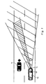
- a monitoring vehicle 10 is traveling in the right lane and is being overtaken by a vehicle 12 to be detected.
- a radar device 14 measures the relative speed of the vehicle 12 to be detected in relation to the monitoring vehicle 10 and delivers a corresponding signal.
- a speed measuring arrangement 16 for example a tachometer, which likewise supplies a corresponding signal.
- a recording device 18 serves to record the vehicle 12 to be recorded. The recording device 18 is triggered by a trigger device 20 that can be triggered automatically at adjustable limit speeds.
- a summing device 22 receives the signal from the speed measuring arrangement 16 via a line 24. The summing device 22 delivers a signal corresponding to the sum of the two speeds. That sum corresponds to the absolute speed of the vehicle 12 to be detected.
- This signal is applied to a comparison device 30 via a line 28.
- the comparison device 30 the absolute speed of the vehicle 12 to be detected is compared with an input limit value. If the absolute speed of the vehicle 12 to be detected exceeds the entered limit value, the comparison device 30 supplies a signal to the triggering device 20 via a line 32.
- the signal from the radar device 14 is also applied to a comparison device 34, which supplies a signal via a line 36 to a lock 38 for the triggering device 20 when the relative speed of the vehicle 12 to be monitored, which is measured with the radar device 14, can be entered into the comparison device 34 Falls below the limit.
- the signal from the speed measuring arrangement 16 is also applied to a comparison device 40, which supplies a signal via a line 42 to a lock 44 for the triggering device 20 when the speed of the monitoring vehicle 10 measured with the speed measuring arrangement 16 has a lower limit value entered in the comparison device 40 falls below.
- a warning device 46 is coupled to the comparison device 40, which provides an acoustic and / or optical signal to the driver when the monitoring vehicle 10 falls below or exceeds the lower or upper limit value entered in the comparison device 40.
- a switch (not shown in FIG. 1) can be switched on and off Speed controllers can be provided, by means of which the speed of the monitoring vehicle 10 is automatically kept between the limit values entered in the comparison device 40.
- the speed signals from the radar device 14, from the speed measuring arrangement 16 and from the summing device 22 are fed via lines 48, 50 and 52 to a digital display device 54, which is described in more detail below with reference to FIG. 3.
- the display device 54 includes at least a display 56 of the relative speed of the vehicle 12 to be monitored, a display 58 of the speed of the monitoring vehicle 10 and a display 60 of the absolute speed of the vehicle 12 to be detected.
- the automatic of the triggering device 20, ie the signaling of the triggering device 20 controlled by the comparison devices 30, 34 and 40, can be switched off.
- Switches 62, 66 and 70 and pushbuttons 64, 68, 72 and 74 are used for this purpose, for example.
- the recording device can be triggered manually if, for example, the monitoring vehicle travels at the same speed behind the vehicle to be detected. It is also possible thereby to park the surveillance vehicle 10 on the roadside and to use the traffic monitoring system as a stationary radar system.
- the traffic monitoring device must be adjustable in several defined positions with respect to the monitoring vehicle 10.
- the traffic monitoring device is arranged pivotably and can be locked in several positions. Otherwise, these types of traffic monitoring are known and are not described in detail here.
- the relative and absolute speeds of the vehicle 12 to be detected and the speed of the monitoring vehicle 10 are registered on the recording obtained by means of the recording device 18.
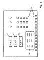
- FIG. 3 An embodiment of the display device 54 is shown schematically in FIG. 3.
- the upper display 58 shows the speed of the monitoring vehicle 10
- the middle display 56 the relative speed
- the lower display 60 the absolute speed of the vehicle 12 to be detected.
- a display is designated by 76, in which further information, such as e.g. Time information can be displayed.
- Such display devices are already used in conventional traffic monitoring systems and are therefore not described in detail here.
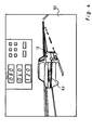
- the recording device 18 is preferably a photographic camera for producing a photographic documentation 80 of the vehicle 12 to be recorded, which is shown in FIG. 4.
- the display device 54 is reflected in the photographic documentation 80 and the current mode of operation of the traffic monitoring device is displayed. However, it is also possible to e.g. to hold onto the edge of the film.
- a lower limit value is entered into the comparison device 34 for the speed of the vehicle to be detected, measured with the radar device 14. This limit value depends on the accuracy range of the radar device 14 and should be 20 km / h in the numerical example given here.
- a lower and an upper limit value are input into the comparison device 40 for the speed of the monitoring vehicle 10 measured with the speed measuring arrangement 16.
- the lower limit depends on the accuracy range of the speed measuring arrangement 16 and is specified here at 25 km / h.
- a limit value is also entered into the comparison device 30 for the absolute speed of the vehicle 12 to be detected, which is obtained by the summing device 22, and which corresponds to the maximum permitted speed and is therefore 100 km / h here.
- the speed of this vehicle 12 is measured by means of the radar device 14. Only when the speed of the vehicle 12 exceeds the maximum permitted speed of 100 km / h, for example 120 km / h, is the triggering device 20 acted upon by a trigger signal from the comparison device 30, so that the recording device 18 is triggered.
- a photographic documentation 80 of the vehicle 12 to be recorded is produced, for example, by means of suitable optics and suitable arrangement of the radar device 14 and the recording device 18 ensures that the vehicle 12 and the vehicle registration number 82 are clearly recognizable and that the vehicle 12 occupies a central position in the documentation 80. Reflected in the documentation 80, the display device 54 also appears with the corresponding information (see FIG. 4).
- the displayed relative speed of the vehicle 12 to be recorded and the displayed speed of the monitoring vehicle 10 serve not only for information, but also for checking the calculated absolute speed of the vehicle 12 to be recorded.
- the triggering device 20 is acted upon and blocked by the comparison device 40. If the monitoring vehicle 10 is driving faster than the upper limit speed 80 km / h entered into the comparison device 40, e.g. 95 km / h, then the vehicles 12, which drive at a speed between 100 km / h and 115 km / h, are not detected in an undesirable manner. In order to avoid such a falling below or exceeding the limit values, the comparison device 40 is coupled to a warning device which delivers a signal to the driver when the limit values are fallen short of or exceeded.
- a speed controller can also be provided, by means of which the speed of the monitoring vehicle 10 is automatically kept between the limit values entered in the comparison device 40.
- the monitoring vehicle 10 With this traffic monitoring device, the detection of all vehicles exceeding a maximum permissible speed is achieved without taking too many pictures, the monitoring vehicle 10 need not maintain a predetermined, constant speed, but can adapt completely to the traffic.
Landscapes
- Engineering & Computer Science (AREA)
- Physics & Mathematics (AREA)
- Remote Sensing (AREA)
- General Physics & Mathematics (AREA)
- Radar, Positioning & Navigation (AREA)
- Computer Networks & Wireless Communication (AREA)
- Electromagnetism (AREA)
- Chemical & Material Sciences (AREA)
- Combustion & Propulsion (AREA)
- Transportation (AREA)
- Mechanical Engineering (AREA)
- Traffic Control Systems (AREA)
- Radar Systems Or Details Thereof (AREA)
- Emergency Alarm Devices (AREA)
Description
Die Erfindung betrifft eine Verkehrsüberwachungseinrichtung, insbesondere zum Einsatz in einem sich bewegenden Überwachungsfahrzeug (10), enthaltend
- (a) ein Messgerät, z.B. ein Radargerät, zur Messung der Relativgeschwindigkeit eines zu erfassenden Fahrzeuges bezogen auf die Geschwindigkeit des Überwachungsfahrzeuges,
- (b) eine Geschwindigkeitsmessanordnung zur Messung der Geschwindigkeit des Überwachungsfahrzeuges,
- (c) eine photographische Aufnahmeeinrichtung zur Aufnahme des zu erfassenden Fahrzeuges,
- (d) eine Auswerteschaltung zur Bestimmung der Geschwindigkeit des zu erfassenden Fahrzeugs aus der gemessenen Relativgeschwindigkeit des zu erfassenden Fahrzeugs und der gemessenen Geschwindigkeit des Überwachungsfahrzeugs, und
- (e) eine Auslösevorrichtung zum Auslösen der Aufnahmeeinrichtung bei Überschreiten einer vorwählbaren Grenzgeschwindigkeit durch das zu erfassende Fahrzeug.
- (a) a measuring device, for example a radar device, for measuring the relative speed of a vehicle to be detected in relation to the speed of the monitoring vehicle,
- (b) a speed measuring arrangement for measuring the speed of the monitoring vehicle,
- (c) a photographic recording device for recording the vehicle to be recorded,
- (d) an evaluation circuit for determining the speed of the vehicle to be detected from the measured relative speed of the vehicle to be detected and the measured speed of the monitoring vehicle, and
- (e) a triggering device for triggering the recording device when a preselectable limit speed is exceeded by the vehicle to be detected.
Eine solche Verkehrsüberwachungseinrichtung dient zur Erstellung einer beispielsweise photographischen Dokumentation als Beweis für eine Übertretung von Verkehrsregeln.Such a traffic monitoring device is used to create, for example, photographic documentation as evidence of a violation of traffic rules.
Es ist bekannt, die Fahrtgeschwindigkeit eines Fahrzeuges durch eine stationäre Radaranlage zu messen und zugleich mit dem Fahrzeug ein radargesteuertes Anzeigegerät zu photographieren.It is known to measure the speed of travel of a vehicle by means of a stationary radar system and at the same time to photograph a radar-controlled display device with the vehicle.
Da es in der Regel erforderlich ist, Überwachungsaufnahmen selbsttätig oder durch Fernsteuerung auszulösen, ist es bekannt, für die Verschlüsse eine elektromagnetische Auslösevorrichtung vorzusehen.Since it is generally necessary to trigger surveillance recordings automatically or by remote control, it is known to provide an electromagnetic triggering device for the closures.
Zur Verkehrsüberwachung werden auch Überwachungsfahrzeuge eingesetzt. Durch die DE-C-1 139 315 ist es bekannt, den Verkehr in der Weise zu überwachen, dass das Überwachungsfahrzeug einem zu erfassenden Fahrzeug mit gleicher Geschwindigkeit folgt und durch Photographie des Fahrzeuges und des als Fahrzeuggeschwindigkeitsanzeiger dienenden Tachometers des Überwachungsfahrzeuges nebst Uhrzeit und Datum einen dokumentarischen Beweis für eine Geschwindigkeitsüberschreitung herstellt.Monitoring vehicles are also used for traffic monitoring. From DE-C-1 139 315 it is known to monitor the traffic in such a way that the monitoring vehicle follows a vehicle to be detected at the same speed and by photographing the vehicle and the speedometer of the monitoring vehicle serving as a vehicle speed indicator along with the time and date provides documentary evidence of speeding.
In dem Prospekt TRAFFIPAX-micro speed der Firma Traffipax-Vertrieb, Hildener Strasse 57, 4000 Düsseldorf 13, ist ein Verkehrsradargerät beschrieben, das wahlweise für mobilen und stationären Betrieb ausgebildet ist. Das Gerät ist schwenkbar, so dass die Verkehrsüberwachung im stationären Betrieb wahlweise von der linken oder von der rechten Strassenseite vorgenommen werden kann. Es kann wahlweise der abfliessende und der ankommende Verkehr gemessen und photographisch dokumentiert werden. Im stationären Betrieb sind bei der Überwachung des abfliessenden Verkehrs für Pkw und Lkw jeweils getrennt einstellbare Grenzgeschwindigkeiten vorgesehen. Das Verkehrsradargerät ist wahlweise zum Einbau in Streifenwagen mit fest montierter Halterung für Radar-Antenne oder zur Aufstellung der Radar-Antenne auf Stativ ausgebildet. Bei geeigneten Kraftahrzeugen kann die Antenne unsichtbar hinter dem Grill montiert werden und während der Fahrt dort verbleiben. Für mobilen Einsatz ist das Gerät mit einem elektronischen Tachometer mit Digitalanzeige ausgestattet. Die Einschaltung des Tachometers erfolgt selbsttätig, sobald die Radaranlage abgeschaltet wird. Durch entsprechende Zeichen auf dem erstellten Photo ist es zu erkennen, ob das Gerät mit Radar oder Tachometer betrieben wurde.In the TRAFFIPAX-micro speed brochure from Traffipax-Vertrieb, Hildener Strasse 57, 4000 Düsseldorf 13, a traffic radar device is described, which is optionally designed for mobile and stationary operation. The device can be swiveled so that traffic monitoring in stationary operation can be carried out either from the left or from the right side of the street. The outgoing and the incoming traffic can be measured and documented photographically. In stationary operation, separately adjustable limit speeds are provided for monitoring the outflowing traffic for cars and trucks. The Traffic radar is optionally designed for installation in patrol cars with a permanently mounted bracket for radar antenna or for placing the radar antenna on a tripod. With suitable motor vehicles, the antenna can be hidden behind the grill and remain there while driving. For mobile use, the device is equipped with an electronic tachometer with digital display. The speedometer is switched on automatically as soon as the radar system is switched off. Corresponding characters on the photo taken indicate whether the device was operated with a radar or tachometer.
Es ist unvorteilhaft, wenn das Überwachungsfahrzeug in der erforderlichen Nähe hinter dem zu erfassenden Fahrzeug mit gleicher Geschwindigkeit fahren muss, weil es dann leicht als Polizeifahrzeug erkannt wird. In dem Prospekt GATSO-meter der Firma Gatsometer B.V., Tetterodeweg 10, 2050 AA Overveen, ist eine Anlage der eingangs genannten Art erwähnt, die ebenfalls wahlweise zum mobilen oder stationären Betrieb einsetzbar ist. Bei dieser Anlage ist es Zusätzlich möglich, die Radarüberwachung und die Tachometerüberwachung in der Weise zu benutzen, dass das Überwachungsfahrzeug mit konstanter Geschwindigkeit aber langsamer als das zu erfassende Fahrzeug fährt. Die Geschwindigkeit des Überwachungsfahrzeuges und die mit der Radaranlage gemessene Relativgeschwindigkeit des zu erfassenden Fahrzeuges bezogen auf die Geschwindigkeit des Überwachungsfahrzeuges werden gemessen und mittels Microcomputer ausgewertet, wobei sich die Geschwindigkeit des zu erfassenden Fahrzeugs als Summe der Geschwindigkeit des Überwachungsfahrzeugs und der Relativgeschwindigkeit des überholenden bzw. zu erfassenden Fahrzeugs ergibt. Als Aufnahmeeinrichtung für die Dokumentation einer möglichen Übertretung von Verkehrsregeln dient eine photographische Kamera, deren Auslösevorrichtung wahlweise durch die Radaranlage oder von Hand betätigt wird. Um ein möglichst unanfechtbares Beweismaterial zu erhalten werden weitere Informationsdaten, wie z.B. Datum und Uhrzeit in der Aufnahme eingeblendet.It is disadvantageous if the surveillance vehicle has to drive behind the vehicle to be detected at the same speed in the required vicinity, because it is then easily recognized as a police vehicle. In the GATSO-meter brochure from Gatsometer BV, Tetterodeweg 10, 2050 AA Overveen, a system of the type mentioned at the beginning is mentioned, which can also be used for mobile or stationary operation. With this system, it is also possible to use the radar monitoring and the tachometer monitoring in such a way that the monitoring vehicle travels at a constant speed but slower than the vehicle to be detected. The speed of the surveillance vehicle and the relative speed of the vehicle to be detected, measured with the radar system, in relation to the speed of the surveillance vehicle are measured and evaluated by means of a microcomputer, the speed of the vehicle to be detected being the sum of the speed of the surveillance vehicle and the relative speed of the overtaking or overtaking detecting vehicle. A serves as a recording facility for documenting a possible violation of traffic rules photographic camera, the triggering device is operated either by the radar system or by hand. In order to obtain evidence that is as indisputable as possible, further information such as the date and time are shown in the recording.
Aus der US-A-4 335 382 ist ein Doppler-Radarsystem zur Verkehrsüberwachung bekannt, das auf entgegenkommende Fahrzeuge anspricht und daher die Summe der Geschwindigkeiten des zu erfassenden Fahrzeugs und des Überwachungsfahrzeugs misst. Von der gemessenen Geschwindigkeitssumme wird in einer kombinierten Zähler-Subtraktionsschaltung die gemessene Geschwindigkeit des Überwachungsfahrzeuges subtrahiert, um die Geschwindigkeit des zu erfassenden Fahrzeugs zu bestimmen, und es sind Anzeigegeräte für die Geschwindigkeit des zu erfassenden Fahrzeuges und die Geschwindigkeit des Überwachungsfahrzeugs vorgesehen. Die Geschwindigkeit des Überwachungsfahrzeugs wird mit einem Messgerät gemessen, das ein der Drehgeschwindigkeit eines Rades des Überwachungsfahrzeuges proportionales Signal liefert, dessen Frequenz mit der Dopplerfrequenz des Radarsystems verglichen und in Abwesenheit von entgegenkommendem Verkehr durch Radarmessung gegenüber der Strasse überwacht und gegebenenfalls korrigiert wird. Durch die besondere Konstruktion der Radaranlage und die Überwachung der Messung der Geschwindigkeit des Überwachungsfahrzeugs sollen Fehlmessungen ausgeschlossen werden.From US-A-4 335 382 a Doppler radar system for traffic monitoring is known which responds to oncoming vehicles and therefore measures the sum of the speeds of the vehicle to be detected and the monitoring vehicle. The measured speed of the monitoring vehicle is subtracted from the measured speed sum in a combined counter-subtraction circuit in order to determine the speed of the vehicle to be detected, and display devices for the speed of the vehicle to be detected and the speed of the monitoring vehicle are provided. The speed of the surveillance vehicle is measured with a measuring device which delivers a signal proportional to the speed of rotation of a wheel of the surveillance vehicle, the frequency of which is compared with the Doppler frequency of the radar system and, in the absence of oncoming traffic, is monitored by radar measurement against the road and corrected if necessary. Due to the special design of the radar system and the monitoring of the measurement of the speed of the monitoring vehicle, incorrect measurements are to be excluded.
Bei einer ähnlichen Anlage nach der US-A-4 293 859 ist eine bestimmte Winkelstellung der Anlage zur Achse des Überwachungsfahrzeugs vorgesehen, um Fehlmessungen durch seitliche Hintergrundsignale einzuschränken.In a similar system according to US-A-4,293,859, a certain angular position of the system relative to the axis of the monitoring vehicle is provided in order to limit incorrect measurements by background signals from the side.
Die US-A-3 206 748 betrifft ein Aufzeichnungsgerät für Fahrzeuggeschwindigkeiten in Verbindung mit einem Überwachungsfahrzeug. Dabei dient eine photographische Kamera zur Aufnahme des zu erfassenden Fahrzeugs und der Registrierung der Geschwindigkeits- und Zeitangaben. Bei stationärem Überwachungsfahrzeug dient ein Radargerät und bei fahrendem Überwachungsfahrzeug dessen Tachometer zur Anzeige der Geschwindigkeit des zu erfassenden Fahrzeugs.US-A-3 206 748 relates to a recording device for Vehicle speeds in connection with a surveillance vehicle. A photographic camera is used to record the vehicle to be recorded and to register the speed and time information. When the surveillance vehicle is stationary, a radar device and when the surveillance vehicle is moving, its tachometer is used to display the speed of the vehicle to be detected.
Die bekannte Verkehrsüberwachungseinrichtung der eingangs genannten Art, die in einem Überwachungsfahrzeug eingebaut ist und zur Geschwindigkeitsüberwachung dient, ist ineffektiv. Einerseits muss das Überwachungsfahrzeug mit konstanter Geschwindigkeit fahren und kann sich also nicht an den gegebenen Verkehr anpassen. Andererseits werden zu viele oder zuu wenige Aufnahmen gemacht, d.h. zu schnell fahrende Fahrzeuge werden ggf. nicht erfasst und es werden Fahrzeuge photographiert, die die zulässige Geschwindigkeit nicht überschreiten. Dies ist z.B. der Fall, wenn das Überwachungsfahrzeug zwar mit konstanter Geschwindigkeit aber zu schnell fährt. Das Überschreiten der zulässigen Geschwindigkeit wird z.T. nicht registriert, da das Radargerät keine überhöhte Geschwindigkeit misst. Wenn das Überwachungsfahrzeug zu langsam fährt, signalisiert die Einrichtung ein in der Tat nicht gegebenes Überschreiten der zulässigen Geschwindigkeit. Die Kamera wird ausgelöst und eine Aufnahme wird gemacht, in der später festgestellt wird, dass kein Überschreiten der zulässigen Geschwindigkeit vorlag.The known traffic monitoring device of the type mentioned at the outset, which is installed in a monitoring vehicle and is used for speed monitoring, is ineffective. On the one hand, the surveillance vehicle has to drive at a constant speed and therefore cannot adapt to the given traffic. On the other hand, too many or too few pictures are taken, i.e. vehicles that are traveling too fast may not be recorded and vehicles that do not exceed the permitted speed will be photographed This is e.g. the case when the surveillance vehicle is traveling at a constant speed but too fast. Exceeding the permissible speed is partly not registered because the radar does not measure excessive speed. If the monitoring vehicle drives too slowly, the device signals that the permissible speed has not been exceeded. The camera is triggered and a picture is taken in which it is later determined that the speed limit was not exceeded.
Der Erfindung liegt die Aufgabe zugrunde, eine Verkehrsüberwachungseinrichtung der eingangs genannten Art so auszubilden, dass das Überwachungsfahrzeug sich dem gegebenen Verkehr anpassen kann und alle eine maximal zulässige Geschwindigkeit überschreitenden Fahrzeuge auch erfasst werden, ohne dass überflüssige Aufnahmen gemacht werden.The invention is based on the object of designing a traffic monitoring device of the type mentioned at the outset in such a way that the monitoring vehicle detects it can adapt to the prevailing traffic and all vehicles exceeding the maximum permissible speed can also be recorded without unnecessary pictures being taken.
Erfindungsgemäss wird diese Aufgabe dadurch gelösst, dass
- (f) die Auswerteschaltung mit einem Relativgeschwindigkeitssignal des Messgerätes zur Messung der Relativgeschwindigkeit des zu erfassenden Fahrzeuges, mit einem Geschwindigkeitssignal der Geschwindigkeitsmessanordnung des Überwachungsfahrzeuges, einem einstellbaren Grenzgeschwindigkeitssignal entsprechend einer vorwählbaren Grenzgeschwindigkeit, einem unteren Grenzwert für das Geschwindigkeitssignal und einem unteren Grenzwert für das Relativgeschwindigkeitssignal beaufschlagt ist und mit der Auslösevorrichtung verbunden ist,
- (g) die Auswerteschaltung enthält
- (g1) eine Vergleichseinrichtung zum Vergleich des einstellbaren Grenzgeschwindigkeitssignals mit dem Relativgeschwindigkeitssignal des Messgerätes zur Messung der Relativgeschwindigkeit des zu erfassenden Fahrzeuges unter Berücksichtigung des Geschwindigkeitssignals der Geschwindigkeitsmessanordnung des Überwachungsfahrzeuges,
- (g2) eine Vergleichseinrichtung zum Vergleich des Geschwindigkeitssignals mit seinem unteren Grenzwert, und
- (g3) eine Vergleichseinrichtung zum Vergleich des Relativgeschwindigkeitssignals mit seinem unteren Grenzwert und
- (h) Mittel zur Erzeugung eines die Auslösevorrichtung betätigenden Auslösesignals, wenn
- (h1) die Vergleichseinrichtung anzeigt, dass die Geschwindigkeit des zu erfassenden Fahrzeugs die vorgewählte Grenzgeschwindigkeit übersteigt, und
- (h2) die Vergleichseinrichtung anzeigt, dass das Geschwindigkeitssignal seinen unteren Grenzwert übersteigt, und
- (h3) die Vergleichseinrichtung anzeigt, dass das Relativgeschwindigkeitssignal seinen unteren Grenzwert übersteigt.
- (f) the evaluation circuit is loaded with a relative speed signal of the measuring device for measuring the relative speed of the vehicle to be detected, with a speed signal of the speed measuring arrangement of the monitoring vehicle, an adjustable limit speed signal corresponding to a preselectable limit speed, a lower limit value for the speed signal and a lower limit value for the relative speed signal and is connected to the triggering device,
- (g) contains the evaluation circuit
- (g1) a comparison device for comparing the adjustable limit speed signal with the relative speed signal of the measuring device for measuring the relative speed of the vehicle to be detected, taking into account the speed signal of the speed measuring arrangement of the monitoring vehicle,
- (g2) a comparison device for comparing the speed signal with its lower limit value, and
- (g3) a comparison device for comparing the relative speed signal with its lower one Limit and
- (h) means for generating a trigger signal actuating the trigger device if
- (h1) the comparison device indicates that the speed of the vehicle to be detected exceeds the preselected limit speed, and
- (h2) the comparator indicates that the speed signal exceeds its lower limit, and
- (h3) the comparator indicates that the relative speed signal exceeds its lower limit.
Dadurch wird die Aufnahmeeinrichtung in Abhängigkeit von der Absolutgeschwindigkeit des zu erfassenden Fahrzeuges ausgelöst, und nicht etwa in Abhängigkeit von der Relativgeschwindigkeit des zu erfassenden Fahrzeuges bezogen auf das Überwachungsfahrzeug.As a result, the recording device is triggered as a function of the absolute speed of the vehicle to be detected, and not as a function of the relative speed of the vehicle to be detected, based on the monitoring vehicle.
Ausgestaltungen der Erfindung sind Gegenstand der Unteransprüche.Embodiments of the invention are the subject of the dependent claims.
Ausführungsbeispiele der Erfindung sind nachstehend unter Bezugnahme auf die zugehörige Zeichnungen näher erläutert.Embodiments of the invention are explained in more detail below with reference to the accompanying drawings.
- Fig. 1Fig. 1
- zeigt eine Verkehrssituation, wobei ein Überwachungsfahrzeug von einem zu erfassenden Fahrzeug überholt wird.shows a traffic situation, wherein a surveillance vehicle is overtaken by a vehicle to be detected.
- Fig. 2Fig. 2
- ist ein Blockdiagramm einer Verkehrsüberwachungseinrichtung nach der Erfindung.is a block diagram of a traffic monitoring device according to the invention.
- Fig. 3Fig. 3
- zeigt schematisch die Anzeigevorrichtung von Fig. 1.shows schematically the display device of FIG. 1.
- Fig. 4Fig. 4
- zeigt eine mittels der Verkehrsüberwachungseinrichtung erzielte, photographische Dokumentation des zu erfassenden Fahrzeuges.shows a photographic documentation of the vehicle to be recorded, obtained by means of the traffic monitoring device.
In Fig. 1 ist eine übliche Verkehrssituation z.B. auf einer Autobahn dargestellt. Ein Überwachungsfahrzeug 10 fährt auf der rechten Spur und wird von einem zu erfassenden Fahrzeug 12 überholt.In Fig. 1 a common traffic situation is e.g. depicted on a highway. A monitoring
In Fig. 2 ist eine erfindungsgemässe Verkehrsüberwachungseinrichtung als Blockdiagramm dargestellt. Ein Radargerät 14 misst die Relativgeschwindigkeit des zu erfassenden Fahrzeuges 12 bezogen auf das Überwachungsfahrzeug 10 und liefert ein entsprechendes Signal. Zur Messung der Geschwindigkeit des Überwachungfahrzeuges 10 ist es mit einer Geschwindigkeitsmessanordnung 16, z.B. einem Tachometer versehen, die ebenfalls ein entsprechendes Signal liefert. Eine Aufnahmeeinrichtung 18 dient zur Aufnahme des zu erfassenden Fahrzeuges 12. Die Aufnahmeeinrichtung 18 wird durch eine bei einstellbaren Grenzgeschwindigkeiten automatisch auslösbare Auslösevorrichtung 20 ausgelöst. Eine Summiereinrichtung 22 wird über eine Leitung 24 mit dem Signal von der Geschwindigkeitsmessanordnung 16 beaufschlagt. Die Summiereinrichtung 22 liefert ein der Summe der beiden Geschwindigkeiten entsprechendes Signal. Diese Summe entspricht der Absolutgeschwindigkeit des zu erfassenden Fahrzeuges 12. Über eine Leitung 28 wird dieses Signal auf eine Vergleichseinrichtung 30 aufgeschaltet. In der Vergleichseinrichtung 30 wird die Absolutgeschwindigkeit des zu erfassenden Fahrzeuges 12 mit einem eingebbaren Grenzwert verglichen. Wenn die Absolutgeschwindigkeit des zu erfassenden Fahrzeuges 12 den eingegebenen Grenzwert überschreitet, liefert die Vergleichseinrichtung 30 über eine Leitung 32 ein Signal an die Auslösevorrichtung 20.2 shows a traffic monitoring device according to the invention as a block diagram. A
Das Signal von dem Radargerät 14 wird ebenfalls auf eine Vergleichseinrichtung 34 aufgeschaltet, die ein Signal über eine Leitung 36 an eine Sperre 38 für die Auslösevorrichtung 20 liefert, wenn die mit dem Radargerät 14 gemessene Relativgeschwindigkeit des zu überwachenden Fahrzeuges 12 einen in der Vergleichseinrichtung 34 eingebbaren Grenzwert unterschreitet.The signal from the
Das Signal von der Geschwindigkeitsmessanordnung 16 wird ebenfalls auf eine Vergleichseinrichtung 40 aufgeschaltet, die ein Signal über eine Leitung 42 an eine Sperre 44 für die Auslösevorrichtung 20 liefert, wenn die mit der Geschwindigkeitsmessanordnung 16 gemessene Geschwindigkeit des Überwachungsfahrzeuges 10 einen in der Vergleichseinrichtung 40 eingegebenen unteren Grenzwert unterschreitet.The signal from the speed measuring arrangement 16 is also applied to a
Zur Geschwindigkeitskontrolle des Überwachungsfahrzeuges 10 ist an der Vergleichseinrichtung 40 eine Warnvorrichtung 46 gekoppelt, welche ein akustisches und/oder optisches Signal an den Fahrer liefert, wenn das Überwachungsfahrzeug 10 den in der Vergleichseinrichtung 40 eingegebenen unteren oder oberen Grenzwert unter- bzw. überschreitet. Weiterhin oder alternativ dazu kann ein (in Fig. 1 nicht dargestellter) ein- und ausschaltbarer Geschwindigkeitsregler vorgesehen sein, mittels dessen die Geschwindigkeit des Überwachungsfahrzeuges 10 automatisch zwischen den in der Vergleichseinrichtung 40 eingegebenen Grenzwerten gehalten wird.For speed control of the
Die Geschwindigkeitssignale von dem Radargerät 14, von der Geschwindigkeitsmeßanordnung 16 und von der Summiereinrichtung 22 werden über Leitungen 48, 50 bzw. 52 einer digitalen Anzeigevorrichtung 54 zugeführt, die unten anhand von Fig. 3 näher beschrieben wird. Die Anzeigevorrichtung 54 beinhaltet zumindest eine Anzeige 56 der Relativgeschwindigkeit des zu überwachenden Fahrzeuges 12, eine Anzeige 58 der Geschwindigkeit des Überwachungsfahrzeuges 10 und eine Anzeige 60 der Absolutgeschwindigkeit des zu erfassenden Fahrzeuges 12.The speed signals from the
Die Automatik der Auslösevorrichtung 20, d.h. die durch die Vergleichseinrichtungen 30, 34 und 40 gesteuerte Signalbeaufschlagung der Auslösevorrichtung 20, ist ausschaltbar. Zu diesem Zweck dienen beispielsweise Schalter 62, 66 und 70 sowie Druckknöpfe 64, 68, 72 und 74. Hierdurch kann die Aufnahmevorrichtung manuell ausgelöst werden, wenn beispielsweise das Überwachungsfahrzeug hinter dem zu erfassenden Fahrzeug mit gleicher Geschwindigkeit fährt. Es ist dadurch ebenfalls möglich, daß Überwachungsfahrzeug 10 am Straßenrand zu parken und die Verkehrsüberwachungsanlage als stationäre Radaranlage zu verwenden. Hierfür muß die Verkehrsüberwachungseinrichtung in mehreren definierten Stellungen bezüglich dem Überwachungsfahrzeug 10 einstellbar sein. Zu diesem Zweck ist die Verkehrsüberwachungseinrichtung schwenkbar angeordnet und in mehreren Stellungen arretierbar. Im übrigen sind diese Arten der Verkehrsüberwachung bekannt und werden hier nicht näher geschildert.The automatic of the triggering
Wie in Fig. 2 gestrichelt angedeutet, sind die Relativund Absolutgeschwindigkeiten des zu erfassenden Fahrzeuges 12 sowie die Geschwindigkeit des Überwachungsfahrzeuges 10 auf der mittels der Aufnahmevorrichtung 18 erzielten Aufnahme registriert.As indicated by dashed lines in FIG. 2, the relative and absolute speeds of the
In Fig. 3 ist eine Ausführungsform der Anzeigevorrichtung 54 schematisch dargestellt. Beispielsweise zeigt die obere Anzeige 58 die Geschwindigkeit des Überwachungsfahrzeuges 10, die mittlere Anzeige 56 die Relativgeschwindigkeit und die untere Anzeige 60 die Absolutgeschwindigkeit des zu erfassenden Fahrzeuges 12 an. Mit 76 ist ein Display bezeichnet, in welcher weitere, mittels Bedienungstasten 78 einstellbare Informationen, wie z.B. Zeitinformationen dargestellt werden. Solche Display-Vorrichtungen finden schon in üblichen Verkehrsüberwachungsanlagen Verwendung und werden deshalb hier nicht näher beschrieben.An embodiment of the
Die Aufnahmevorrichtung 18 ist vorzugsweise eine photographische Kamera zur Erstellung einer in Fig. 4 dargestellten photographischen Dokumentation 80 des zu erfassenden Fahrzeuges 12. Die Anzeigevorrichtung 54 ist in der photographischen Dokumentation 80 eingespiegelt und die momentane Betriebsweise der Verkehrsüberwachungseinrichtung wird angezeigt. Es ist aber auch möglich, die Informationen z.B. auf dem Filmrand festzuhalten.The
In die Vergleichseinrichtung 34 für die mit dem Radargerät 14 gemessene Geschwindigkeit des zu erfassenden Fahrzeuges wird ein unterer Grenzwert eingegeben. Dieser Grenzwert richtet sich nach dem Genauigkeitsbereich des Radargerätes 14 und soll in dem hier aufgeführten Zahlenbeispiel 20 km/h betragen.A lower limit value is entered into the
In die Vergleichseinrichtung 40 für die mit der Geschwindigkeitsmeßanordnung 16 gemessene Geschwindigkeit des Überwachungsfahrzeuges 10 wird ein unterer und ein oberer Grenzwert eingegeben. Der untere Grenzwert richtet sich nach dem Genauigkeitsbereich der Geschwindigkeitsmeßanordnung 16 und wird hier mit 25 km/h angegeben. Der obere Grenzwert richtet sich nach der an der betreffenden Straßenabschnitt maximal erlaubten Geschwindigkeit und dem unteren Grenzwert für die mit dem Radargerät 14 gemessene Geschwindigkeit. Diesen oberen Grenzwert erhält man durch Subtrahieren des unteren Grenzwertes für die mit dem Radargerät 14 gemessene Geschwindigkeit von der maximal erlaubten Geschwindigkeit. In dem hier aufgeführten Zahlenbeispiel wird angenommen, daß die maximal erlaubte Geschwindigkeit 100 km/h beträgt. Hier beträgt demnach der obere Grenzwert der Vergleichseinrichtung 40 80 km/h (100 km/h - 20 km/h = 80 km/h).A lower and an upper limit value are input into the
In die Vergleichseinrichtung 30 für durch die Summiereinrichtung 22 erhaltene Absolutgeschwindigkeit des zu erfassenden Fahrzeuges 12 wird ebenfalls ein Grenzwert eingegeben, der mit der maximal erlaubten Geschwindigkeit übereinstimmt und hier also 100 km/h beträgt.A limit value is also entered into the
Wenn das Überwachungsfahrzeug 10 von einem Fahrzeug 12 überholt wird, wird die Geschwindigkeit dieses Fahrzeuges 12 mittels des Radargerätes 14 gemessen. Nur wenn die Geschwindigkeit des Fahrzeuges 12 die maximal erlaubte Geschwindigkeit von 100 km/h überschreitet, z.B. 120 km/h beträgt, wird die Auslösevorrichtung 20 mit einem Auslösesignal von der Vergleichseinrichtung 30 beaufschlagt, so daß die Aufnahmevorrichtung 18 ausgelöst wird. Es entsteht z.B. eine photographische Dokumentation 80 des zu erfassenden Fahrzeuges 12. Durch geeignete Optik und geeignete Anordnung des Radargerätes 14 und die Aufnahme-Vorrichtung 18 wird gewährleistet, dass das Fahrzeug 12 und das Fahrzeugkennzeichen 82 gut erkennbar sind, und dass das Fahrzeug 12 eine zentrale Position in der Dokumentation 80 einnimmt. In der Dokumentation 80 eingespiegelt erscheint auch die Anzeigevorrichtung 54 mit den entsprechenden Angaben (s. Fig. 4). Die angezeigte Relativgeschwindigkeit des zu erfassenden Fahrzeuges 12 und die angezeigte Geschwindigkeit des Überwachungsfahrzeuges 10 dienen dabei nicht nur zur Information, sondern auch zur Überprüfung der errechneten Absolutgeschwindigkeit des zu erfassenden Fahzreuges 12.When the
Wenn das Überwachungsfahrzeug 10 langsamer als die in der Vergleichseinrichtung 40 eingegebene untere Grenzgeschwindigkeit 25 km/h fährt, 50 dass die Geschwindigkeitsmessanordnung einen zu ungenauen Wert liefert, wird die Auslösevorrichtung 20 mit einem Sperrsignal von der Vergleichseinrichtung 40 beaufschlagt und gesperrt. Fährt das Überwachungsfahrzeug 10 schneller als die in die Vergleichseinrichtung 40 eingegebene obere Grenzgeschwindigkeit 80 km/h, z.B. 95 km/h, dann werden die Fahrzeuge 12, die mit einer Geschwindigkeit zwischen 100 km/h und 115 km/h fahren, in unerwünschter Weise nicht erfasst. Um ein solches Unter- bzw. Überschreiten der Grenzwerte zu vermeiden, ist die Vergleichsvorrichtung 40 mit einer Warnvorrichtung gekoppelt, die ein Signal an den Fahrer liefert, wenn die Grenzwerte unter- bzw. überschritten werden.If the
Es kann auch ein Geschwindigkeitsregler vorgesehen sein, mittels dessen die Geschwindigkeit des Überwachungsfahrzeuges 10 automatisch zwischen den in der Vergleichseinrichtung 40 eingegebenen Grenzwerten gehalten wird.A speed controller can also be provided, by means of which the speed of the
Mit dieser Verkehrsüberwachungseinrichtung wird also das Erfassen aller eine maximal zulässige Geschwindigkeit überschreitenden Fahrzeuge erreicht, ohne dass zu viele Aufnahmen gemacht werden, wobei das Überwachungsfahrzeug 10 keine vorgegebene, konstante Geschwindigkeit einzuhalten braucht, sondern sich dem Verkehr völlig anpassen kann.With this traffic monitoring device, the detection of all vehicles exceeding a maximum permissible speed is achieved without taking too many pictures, the monitoring
Claims (13)
- Traffic monitoring device, particularly for application in a moving monitoring vehicle (10), comprising(a) a measuring instrument, e.g. a radar instrument (14), for measuring the relative speed of a vehicle (12) to be detected with respect to the speed of the monitoring vehicle (10),(b) a speed measuring arrangement (16) for measuring the speed of the monitoring vehicle (10),(c) a photographic recording device (18) for recording the vehicle (12) to be detected,(d) an evaluation circuit for determination of the speed of the vehicle (12) to be detected from the measured relative speed of the vehicle (12) to be detected and the measured speed of the monitoring vehicle (10), and(e) a trigger device (20) for triggering the recording device (18) when the vehicle to be detected is exceeding a predetermined limit speed,
characterized in that
(f) a relative speed signal from the meassuring instrument for measuring the relative speed of the vehicle (12) to be detected, a speed signal from the speed measuring arrangement (16) of the monitoring vehicle (10), an adjustable limit speed signal corresponding to a predetermined limit speed, a lower limit value for the speed signal and a lower limit value for the relative speed signal are applied to the evaluation circuit and the evaluation circuit is connected to the trigger device (20),(g) the evaluation circuit comprises(g₁) a first comparator (30) for comparing the adjustable limit speed signal with the relative speed signal of the measuring instrument for measuring the relative speed of the vehicle to be detected by taking into account the speed signal of the speed measuring arrangement of the monitoring vehicle (10),(g₂) a second comparator (40) for comparing the speed signal of the monitoring vehicle (10) with its lower limit value, and(g₃) a third comparator (34) for comparing the relative speed signal with its lower limit value, and(h) means (30, 44, 38) for generating a trigger signal actuating the trigger device when(h₁) the first comparator (30) indicates that the speed of the vehicle (12) to be detected exceeds the predetermined limit speed, and (h₂) the second comparator (40) indicates that the speed signal of the monitoring vehicle (10) exceeds its lower limit value, and(h₃) the third comparator (34) indicates that the relative speed signal exceeds its lower limit value. - Traffic monitoring device as set forth in claim 1, characterized in that a warning device (46) adapted to be turned-on and -off is provided, which supplies an acoustic and/or optical signal when the speed signal from the speed measuring arrangement (16) of the monitoring vehicle (10) drops below its lower limit value.
- Traffic monitoring device as set forth in claim 1 or 2, characterized in that a warning device (46) adapted to be turned-on and -off is provided, which supplies an acoustic and/or optical signal when the speed signal from the speed measuring arrangement (16) of the monitoring vehicle (10) exceeds a predeterminable upper limit value.
- Traffic monitoring device as set forth in any one of the claims 2 and 3, characterized in that a speed controller adapted to be turned-on and -off is provided, by means of which the speed of the monitoring vehicle (10) automatically is kept between the predeterminable limit values.
- Traffic monitoring device as set forth in any one of the preceding claims, characterized in that a digital indication device (54) is provided for indicating the relative and absolute speed of the vehicle (12) to be detected and the speed of the monitoring vehicle (10).
- Traffic monitoring device as set forth in any one of the preceding claims, characterized in that the means 30, 44, 38) for generating the trigger signal for the trigger device (20) is adapted to be turned-off such that the trigger device (20) either is adapted to be manually actuated or the traffic monitoring device is adapted to be used in the form of a stationary radar device.
- Traffic monitoring device as set forth in claim 5, characterized in that the relative and absolute speeds of the vehicle (12) to be detected and the speed of the monitoring vehicle (10) are adapted to be registered in the picture achieved by means of the recording device (18).
- Traffic monitoring device as set forth in any one of the preceding claims, characterized in that the recording device (18) is a photographic camera for preparing a photographic documentation (80) of the vehicle (12) to be detected.
- Traffic monitoring device as set forth in claim 8, characterized in that the indication device (54) is reflected in the photographic documentation (80).
- Traffic monitoring device as set forth in claim 6, characterized in that the momentaneous operating mode of the traffic monitoring device is adapted to be indicated and registered.
- Traffic monitoring device as set forth in any one of the claims 6 to 10, characterized in that it is arranged pivotably.
- Traffic monitoring device as set forth in claim 11, characterized in that it is adapted to be stopped in one or several positions.
- Traffic monitoring device as set forth in any one of the preceding claims, characterized in that it is adapted to be removed.
Applications Claiming Priority (2)
| Application Number | Priority Date | Filing Date | Title |
|---|---|---|---|
| DE3728401 | 1987-08-26 | ||
| DE19873728401 DE3728401A1 (en) | 1987-08-26 | 1987-08-26 | TRAFFIC MONITORING DEVICE |
Publications (3)
| Publication Number | Publication Date |
|---|---|
| EP0304626A2 EP0304626A2 (en) | 1989-03-01 |
| EP0304626A3 EP0304626A3 (en) | 1990-07-11 |
| EP0304626B1 true EP0304626B1 (en) | 1991-10-02 |
Family
ID=6334482
Family Applications (1)
| Application Number | Title | Priority Date | Filing Date |
|---|---|---|---|
| EP88111760A Expired - Lifetime EP0304626B1 (en) | 1987-08-26 | 1988-07-21 | Traffic-monitoring device |
Country Status (6)
| Country | Link |
|---|---|
| US (1) | US4988994A (en) |
| EP (1) | EP0304626B1 (en) |
| JP (1) | JPS6468900A (en) |
| CA (1) | CA1316583C (en) |
| DD (1) | DD282312A5 (en) |
| DE (2) | DE3728401A1 (en) |
Families Citing this family (46)
| Publication number | Priority date | Publication date | Assignee | Title |
|---|---|---|---|---|
| DE3908069A1 (en) * | 1989-03-13 | 1990-09-20 | Bauer Secundus Kunz Dieter Dip | Device and circuit arrangement for measuring, recording and displaying the speed of a moving object, for example a vehicle |
| FR2648905B1 (en) * | 1989-06-26 | 1994-06-17 | Est Ctre Etu Techn Equipement | DEVICE FOR ASSESSING THE BEHAVIOR OF ROAD USERS |
| DE4013037A1 (en) * | 1990-04-24 | 1991-10-31 | Standard Elektrik Lorenz Ag | Method of mobile traffic surveillance - using moving detector vehicle with radar which detects speed of vehicles being observed |
| DE4102460A1 (en) * | 1991-01-28 | 1992-07-30 | Siemens Ag | METHOD AND DEVICE FOR DETECTING VEHICLES IN ROAD TRAFFIC FOR CONTROLLING A TRAFFIC SIGNAL SYSTEM |
| DE4115770A1 (en) * | 1991-05-15 | 1992-11-19 | Robot Foto Electr Kg | TRAFFIC MONITORING DEVICE |
| CH690342A5 (en) * | 1992-08-14 | 2000-07-31 | Multanova Ag | Method and apparatus for securing that appears in an image data. |
| DE4326398C1 (en) * | 1993-08-06 | 1994-07-21 | Leica Sensortechnik Gmbh | Traffic monitoring method and device |
| US5515042A (en) * | 1993-08-23 | 1996-05-07 | Nelson; Lorry | Traffic enforcement device |
| US5381155A (en) * | 1993-12-08 | 1995-01-10 | Gerber; Eliot S. | Vehicle speeding detection and identification |
| DE4400624A1 (en) * | 1994-01-12 | 1995-07-13 | Conner Joe Scott O | Vehicle speed measurement installation for traffic monitoring |
| US5491464A (en) * | 1994-03-14 | 1996-02-13 | Carter; Conrad C. | Remotely controlled radar gun and video recording apparatus |
| US5382953A (en) * | 1994-04-14 | 1995-01-17 | Hauptli; Wayne L. | Device for detecting school bus stop arm violations |
| AT400641B (en) * | 1994-04-22 | 1996-02-26 | Jeitschko Stefan | Device for measuring (detecting), displaying and recording the speed of a vehicle |
| KR960003444A (en) * | 1994-06-01 | 1996-01-26 | 제임스 디. 튜턴 | Vehicle surveillance system |
| KR960001777A (en) * | 1994-06-01 | 1996-01-25 | 제임스 디. 튜턴 | Frequency Domain Processing Method of Doppler Signal for Vehicle Surveillance System |
| GB2304445B (en) * | 1994-10-06 | 1998-01-28 | Eliot S Gerber | Vehicle speeding detection and identification |
| US5565871A (en) * | 1995-02-10 | 1996-10-15 | Applied Concepts Inc. | Police traffic radar for allowing manual rejection of incorrect patrol speed display |
| US6111523A (en) | 1995-11-20 | 2000-08-29 | American Traffic Systems, Inc. | Method and apparatus for photographing traffic in an intersection |
| US5938717A (en) * | 1996-03-04 | 1999-08-17 | Laser Technology, Inc. | Speed detection and image capture system for moving vehicles |
| ES2195127T3 (en) * | 1996-04-01 | 2003-12-01 | Gatsometer Bv | METHOD AND APPLIANCE TO DETERMINE THE SPEED AND SITUATION OF A VEHICLE. |
| US5948038A (en) | 1996-07-31 | 1999-09-07 | American Traffic Systems, Inc. | Traffic violation processing system |
| SE510918C2 (en) * | 1997-08-11 | 1999-07-05 | Volvo Ab | displays Instruments |
| US6046686A (en) * | 1997-09-18 | 2000-04-04 | Kustom Signals, Inc. | Violation alert speed display |
| DE19900005A1 (en) * | 1999-01-02 | 2000-12-21 | Peter Mesenbrock | Radar speed monitoring equipment combined with sound level recording equipment to simultaneously check whether motorists are exceeding either speed or sound limits |
| DE19916793A1 (en) * | 1999-04-14 | 2000-10-19 | Robot Foto Electr Kg | Process for applying data to a photographic film |
| DE19919248A1 (en) * | 1999-04-28 | 2000-11-02 | Robot Foto Electr Kg | Traffic monitoring device |
| US6424272B1 (en) * | 2001-03-30 | 2002-07-23 | Koninklijke Philips Electronics, N.V. | Vehicular blind spot vision system |
| US6696978B2 (en) * | 2001-06-12 | 2004-02-24 | Koninklijke Philips Electronics N.V. | Combined laser/radar-video speed violation detector for law enforcement |
| US6744379B1 (en) | 2001-08-16 | 2004-06-01 | Applied Concepts, Inc. | System and method for displaying radar data |
| DE10152620A1 (en) * | 2001-10-25 | 2003-05-08 | Bayerische Motoren Werke Ag | Motor vehicle automatic speed and distance control system, has an additional function that allows recording and display of other vehicles within the measurement range of its distance sensor |
| DE10225921B4 (en) * | 2002-06-11 | 2007-05-31 | Hermann Eser | Speed measurement system |
| DE60219176D1 (en) * | 2002-10-30 | 2007-05-10 | Monnier Bernard | Device for monitoring the speed of vehicles |
| FR2847755B1 (en) * | 2002-11-26 | 2005-04-22 | Cynove | IMAGE AUTHENTICATION METHODS |
| US7091901B2 (en) * | 2004-05-14 | 2006-08-15 | Kustom Signals, Inc. | Traffic radar system with improved patrol speed capture |
| US8436730B2 (en) | 2007-10-04 | 2013-05-07 | Sc Holdings, Llc | Method and system for tracking and/or disabling a vehicle |
| US20090237271A1 (en) * | 2008-03-21 | 2009-09-24 | John Sundstrom | Device for prevention of speeding, and method thereof |
| US20100006908A1 (en) * | 2008-07-09 | 2010-01-14 | Brady Frederick T | Backside illuminated image sensor with shallow backside trench for photodiode isolation |
| US20100013672A1 (en) * | 2008-07-17 | 2010-01-21 | Quintos Iii Mel Francis P | Photographic multiple vehicular traffic ticket issuance system |
| US7705772B1 (en) | 2009-01-19 | 2010-04-27 | Kustom Signals, Inc. | Traffic radar with target duration tracking |
| WO2012068064A1 (en) | 2010-11-15 | 2012-05-24 | Image Sensing Systems, Inc. | Hybrid traffic sensor system and associated method |
| US9472097B2 (en) | 2010-11-15 | 2016-10-18 | Image Sensing Systems, Inc. | Roadway sensing systems |
| DE102011056366B3 (en) * | 2011-12-13 | 2012-09-13 | Alfadynamics GmbH | Method for controlling vehicle such as motor vehicle, involves acknowledging and registering autonomous optical signal produced in series arrangement with activation of radio signals in display to checkpoint by photographing vehicle |
| US10984253B2 (en) | 2013-06-06 | 2021-04-20 | Kustom Signals, Inc. | Traffic enforcement system with time tracking and integrated video capture |
| JP7009987B2 (en) * | 2017-12-27 | 2022-01-26 | トヨタ自動車株式会社 | Automatic driving system and automatic driving method |
| US10810872B2 (en) * | 2018-07-31 | 2020-10-20 | Baidu Usa Llc | Use sub-system of autonomous driving vehicles (ADV) for police car patrol |
| CN110111579A (en) * | 2019-05-07 | 2019-08-09 | 山东交通学院 | A kind of unattended highway automatic tour inspection system and application method |
Family Cites Families (6)
| Publication number | Priority date | Publication date | Assignee | Title |
|---|---|---|---|---|
| US3165373A (en) * | 1962-09-07 | 1965-01-12 | Mid Continent Insurance Compan | Traffic speed violation recorder |
| US3206748A (en) * | 1962-12-27 | 1965-09-14 | Miller Robert William | Vehicle speed recording apparatus |
| US3680043A (en) * | 1969-11-25 | 1972-07-25 | Paul Angeloni | Vehicle speed monitoring systems |
| US4335383A (en) * | 1979-02-12 | 1982-06-15 | Kustom Electronics, Inc. | Method and apparatus for digitally determining the speed of a target vehicle while the radar platform vehicle is in motion |
| US4293859A (en) * | 1979-09-14 | 1981-10-06 | M. P. H. Industries, Inc. | Traffic radar unit |
| US4335382A (en) * | 1980-03-10 | 1982-06-15 | Decatur Electronics, Inc. | Traffic radar system |
-
1987
- 1987-08-26 DE DE19873728401 patent/DE3728401A1/en not_active Withdrawn
-
1988
- 1988-07-21 EP EP88111760A patent/EP0304626B1/en not_active Expired - Lifetime
- 1988-07-21 DE DE8888111760T patent/DE3865274D1/en not_active Expired - Fee Related
- 1988-08-11 US US07/231,083 patent/US4988994A/en not_active Expired - Lifetime
- 1988-08-24 DD DD88319165A patent/DD282312A5/en not_active IP Right Cessation
- 1988-08-24 JP JP63208492A patent/JPS6468900A/en active Pending
- 1988-08-25 CA CA000575689A patent/CA1316583C/en not_active Expired - Fee Related
Also Published As
| Publication number | Publication date |
|---|---|
| EP0304626A2 (en) | 1989-03-01 |
| US4988994A (en) | 1991-01-29 |
| JPS6468900A (en) | 1989-03-14 |
| DE3728401A1 (en) | 1989-03-09 |
| DD282312A5 (en) | 1990-09-05 |
| EP0304626A3 (en) | 1990-07-11 |
| DE3865274D1 (en) | 1991-11-07 |
| CA1316583C (en) | 1993-04-20 |
Similar Documents
| Publication | Publication Date | Title |
|---|---|---|
| EP0304626B1 (en) | Traffic-monitoring device | |
| EP1067399B1 (en) | Method of visibility determination | |
| DE19639907A1 (en) | Monitoring vehicle in front | |
| EP1475765A2 (en) | Apparatus for determining the possibility of a passage for a vehicle | |
| WO2007144239A1 (en) | Lane changing aid for motor vehicles | |
| EP1792776B1 (en) | Method for detection and display of a parking space and parking assistance system of a motor vehicle | |
| DE19937489B4 (en) | Method for monitoring a lane change of a motor vehicle | |
| DE102005023185A1 (en) | Lane change assistant for motor vehicles | |
| EP1446678B1 (en) | Method and device for detecting and classifying moving vehicles | |
| DE10030258A1 (en) | Method for controlling the distance of a vehicle from a preceding vehicle and distance control system | |
| EP1037189B1 (en) | Method to display objects for vehicle | |
| EP1375267A2 (en) | Process and system for the detection of an accident risk | |
| EP1577682A1 (en) | Object locating system for vehicles to recognize lane change | |
| EP0741377A1 (en) | Road traffic control system | |
| WO2005069248A1 (en) | Mobile, camera-aided distance and speed meter | |
| DE102004025458A1 (en) | Lane-based automatic turn signal deactivation | |
| EP1422586B1 (en) | Method and device to monitor a car driver by using lane recognition | |
| WO2005122104A1 (en) | System for the photographic monitoring of traffic by means of a video camera | |
| EP0634734A1 (en) | Mobil traffic monitoring system | |
| DE19818236A1 (en) | Monitoring system for detecting a motor vehicle lane change | |
| DE60207965T2 (en) | Driver assistance method and method for vehicle lane change procedures | |
| WO2020187581A1 (en) | Method and device for detecting a traffic law violation due to the allowable distance between a following vehicle and a guide vehicle being undershot | |
| DE10320723B4 (en) | Measuring device in motor vehicles for measuring parking spaces and method for measuring parking spaces | |
| EP1099960B1 (en) | Measuring procedure for the determination and documentation of the distance between two vehicles | |
| DE102005025386A1 (en) | Motor vehicle driver warning method, involves carrying out suppression of warning, when evaluation of driving situation is done before detection and suppressing detection of lane departure when evaluation is done before detection |
Legal Events
| Date | Code | Title | Description |
|---|---|---|---|
| PUAI | Public reference made under article 153(3) epc to a published international application that has entered the european phase |
Free format text: ORIGINAL CODE: 0009012 |
|
| AK | Designated contracting states |
Kind code of ref document: A2 Designated state(s): CH DE FR GB LI NL |
|
| PUAL | Search report despatched |
Free format text: ORIGINAL CODE: 0009013 |
|
| AK | Designated contracting states |
Kind code of ref document: A3 Designated state(s): CH DE FR GB LI NL |
|
| 17P | Request for examination filed |
Effective date: 19900809 |
|
| 17Q | First examination report despatched |
Effective date: 19910128 |
|
| GRAA | (expected) grant |
Free format text: ORIGINAL CODE: 0009210 |
|
| AK | Designated contracting states |
Kind code of ref document: B1 Designated state(s): CH DE FR GB LI NL |
|
| REF | Corresponds to: |
Ref document number: 3865274 Country of ref document: DE Date of ref document: 19911107 |
|
| GBT | Gb: translation of ep patent filed (gb section 77(6)(a)/1977) | ||
| ET | Fr: translation filed | ||
| PLBE | No opposition filed within time limit |
Free format text: ORIGINAL CODE: 0009261 |
|
| STAA | Information on the status of an ep patent application or granted ep patent |
Free format text: STATUS: NO OPPOSITION FILED WITHIN TIME LIMIT |
|
| 26N | No opposition filed | ||
| PGFP | Annual fee paid to national office [announced via postgrant information from national office to epo] |
Ref country code: GB Payment date: 19971112 Year of fee payment: 10 |
|
| PGFP | Annual fee paid to national office [announced via postgrant information from national office to epo] |
Ref country code: FR Payment date: 19971121 Year of fee payment: 10 |
|
| PGFP | Annual fee paid to national office [announced via postgrant information from national office to epo] |
Ref country code: CH Payment date: 19971127 Year of fee payment: 10 |
|
| PGFP | Annual fee paid to national office [announced via postgrant information from national office to epo] |
Ref country code: NL Payment date: 19971130 Year of fee payment: 10 |
|
| PG25 | Lapsed in a contracting state [announced via postgrant information from national office to epo] |
Ref country code: GB Free format text: LAPSE BECAUSE OF NON-PAYMENT OF DUE FEES Effective date: 19980721 |
|
| PG25 | Lapsed in a contracting state [announced via postgrant information from national office to epo] |
Ref country code: LI Free format text: LAPSE BECAUSE OF NON-PAYMENT OF DUE FEES Effective date: 19980731 Ref country code: CH Free format text: LAPSE BECAUSE OF NON-PAYMENT OF DUE FEES Effective date: 19980731 |
|
| PGFP | Annual fee paid to national office [announced via postgrant information from national office to epo] |
Ref country code: DE Payment date: 19980922 Year of fee payment: 11 |
|
| PG25 | Lapsed in a contracting state [announced via postgrant information from national office to epo] |
Ref country code: NL Free format text: LAPSE BECAUSE OF NON-PAYMENT OF DUE FEES Effective date: 19990201 |
|
| GBPC | Gb: european patent ceased through non-payment of renewal fee |
Effective date: 19980721 |
|
| REG | Reference to a national code |
Ref country code: CH Ref legal event code: PL |
|
| PG25 | Lapsed in a contracting state [announced via postgrant information from national office to epo] |
Ref country code: FR Free format text: LAPSE BECAUSE OF NON-PAYMENT OF DUE FEES Effective date: 19990331 |
|
| NLV4 | Nl: lapsed or anulled due to non-payment of the annual fee |
Effective date: 19990201 |
|
| REG | Reference to a national code |
Ref country code: FR Ref legal event code: ST |
|
| PG25 | Lapsed in a contracting state [announced via postgrant information from national office to epo] |
Ref country code: DE Free format text: LAPSE BECAUSE OF NON-PAYMENT OF DUE FEES Effective date: 20000503 |