EP0075111B1 - Tread pattern for pneumatic tyres - Google Patents
Tread pattern for pneumatic tyres Download PDFInfo
- Publication number
- EP0075111B1 EP0075111B1 EP82107461A EP82107461A EP0075111B1 EP 0075111 B1 EP0075111 B1 EP 0075111B1 EP 82107461 A EP82107461 A EP 82107461A EP 82107461 A EP82107461 A EP 82107461A EP 0075111 B1 EP0075111 B1 EP 0075111B1
- Authority
- EP
- European Patent Office
- Prior art keywords
- circumferential
- recesses
- tread pattern
- tyre
- depressions
- Prior art date
- Legal status (The legal status is an assumption and is not a legal conclusion. Google has not performed a legal analysis and makes no representation as to the accuracy of the status listed.)
- Expired
Links
- 230000002093 peripheral effect Effects 0.000 abstract 1
- 230000015556 catabolic process Effects 0.000 description 1
- 238000010276 construction Methods 0.000 description 1
- 230000000149 penetrating effect Effects 0.000 description 1
- 238000005096 rolling process Methods 0.000 description 1
Images
Classifications
-
- B—PERFORMING OPERATIONS; TRANSPORTING
- B60—VEHICLES IN GENERAL
- B60C—VEHICLE TYRES; TYRE INFLATION; TYRE CHANGING; CONNECTING VALVES TO INFLATABLE ELASTIC BODIES IN GENERAL; DEVICES OR ARRANGEMENTS RELATED TO TYRES
- B60C11/00—Tyre tread bands; Tread patterns; Anti-skid inserts
- B60C11/03—Tread patterns
- B60C11/032—Patterns comprising isolated recesses
-
- B—PERFORMING OPERATIONS; TRANSPORTING
- B60—VEHICLES IN GENERAL
- B60C—VEHICLE TYRES; TYRE INFLATION; TYRE CHANGING; CONNECTING VALVES TO INFLATABLE ELASTIC BODIES IN GENERAL; DEVICES OR ARRANGEMENTS RELATED TO TYRES
- B60C19/00—Tyre parts or constructions not otherwise provided for
- B60C2019/006—Warning devices, e.g. devices generating noise due to flat or worn tyres
Definitions
- the invention relates to a tread design for pneumatic tires for spare wheels, with a large number of recesses arranged side by side and one behind the other, which run in an approximately rectangular plan transversely to the tire circumferential direction, and with transverse webs and circumferential webs that separate the depressions from one another and have a width that is approximately 1/4 to 3/4 of the circumferential extent of the adjacent depressions corresponds.
- the invention is therefore based on the object of specifying a tread design which entails an increased noise emission during driving operation.
- the radially outer circumferential surface of the tire is divided into a plurality of successive sections in the circumferential direction, that within each section the circumferential extent of the depressions and the transverse webs is constant and that in the successive sections the circumferential extent of the depressions and the transverse webs is chosen differently.
- the invention offers the advantage of not only an increased noise emission, but an increased proportion of tones of certain frequencies in the driving noise, which have a very penetrating effect on the driver's ear and which become particularly unpleasant at high speeds. This causes the driver to drive slowly enough and to have the spare tire put on after a breakdown immediately replaced by a normal tire in a workshop.
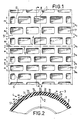
- the center of the tread with the tread design is shown by a line 1, which also shows the tire circumferential direction.
- the tread profile consists essentially of transverse webs 5 which run continuously and continuously from one tread edge to the other tread edge and which are connected via short circumferential webs 6 which extend in the circumferential direction, in such a way that the webs 6 for successive pairs of cross webs are offset from each other.
- the webs 5, 6 delimit essentially transverse rectangular depressions 7 with the width a 1 , which, due to the webs 5, 6, form cell-like enclosures when fully supported on the roadway.
- the width b, the transverse webs 5 is slightly above half the circumferential extent of the depressions 7 or half the mutual spacing of the transverse webs 5. This dimensioning can also apply to the circumferential webs 6, which, however, are at a mutual distance by four times the width of the web.
- the tread design is similar to that in the first.
- “similar” is geometrical, at least with regard to the widths of the transverse webs 5, 5 'and the depressions 7, 7'.
- a 2 denotes the width of a depression 7 'and b 2 that of a transverse web 5' in the second section 4 of the tread.
- the ratio a,: a 2 has the value 4/5.
- each section 3 4, the depressions 7, 7 ', transverse webs 5, 5' and circumferential webs 6, 6 'have the same dimensions, while the profile depth for both sections together is approximately 4 mm.
- the circumferential surface can also be divided into more than two sections, and with two sections it can also be advantageous to choose different lengths for the two sections.
- at least one of the sections should preferably have a length of 25% to 75% of the total circumferential length.
- width ratios a l : a 2 or b 1 : b 2 should be between 6:10 and 9:10.
- tire circumferential surface z. B. to divide into three sections with different widths for the recesses and the webs from section to section, but also in this case the different depressions and crossbars should be geometrically similar.
- tread design not least because of the low tread depth, can be used excellently with both radial and diagonal tires.
Landscapes
- Engineering & Computer Science (AREA)
- Mechanical Engineering (AREA)
- Tires In General (AREA)
Abstract
Description
Die Erfindung betrifft eine Laufflächengestaltung für Fahrzeugluftreifen für Reserveräder, mit in großer Anzahl in Reifenumfangsrichtung nebeneinander und hintereinander angeordneten Vertiefungen, die bei etwa rechteckigem Grundriß quer zur Reifenumfangsrichtung verlaufen, und mit Querstegen und Umfangsstegen, die die Vertiefungen voneinander trennen und eine Breite aufweisen, die etwa 1/4 bis 3/4 der Umfangserstreckung der benachbarten Vertiefungen entspricht.The invention relates to a tread design for pneumatic tires for spare wheels, with a large number of recesses arranged side by side and one behind the other, which run in an approximately rectangular plan transversely to the tire circumferential direction, and with transverse webs and circumferential webs that separate the depressions from one another and have a width that is approximately 1/4 to 3/4 of the circumferential extent of the adjacent depressions corresponds.
Derartige, durch die DE-A-2933485 bekannte, Laufflächengestaltungen sind für Reservereifen für PKW vorgeschlagen worden, um ein geräuschvolles Abrollen des Reifens auf der Straße zu erzielen und um das Gewicht von Reservereifen zu reduzieren.Such tread designs known from DE-A-2933485 have been proposed for spare tires for cars in order to achieve a noisy rolling of the tire on the road and to reduce the weight of spare tires.
Zwar wird mit diesen bekannten Reservereifen eine gegenüber üblichen Reifen erhöhte Geräuschabgabe erzielt, doch hat sich gezeigt, daß die vom Reifen stammenden Fahrgeräusche nicht in allen Fällen ausreichen, um einen PKW-Fahrer darauf hinzuweisen, daß er einen möglichst umgehend auszuwechselnden Reservereifen montiert hat.With these known spare tires, an increased noise emission is achieved compared to conventional tires, but it has been shown that the driving noise coming from the tire is not sufficient in all cases to point out to a car driver that he has fitted a spare tire to be replaced as soon as possible.
Der Erfindung liegt deshalb die Aufgabe zugrunde, eine Laufflächengestaltung anzugeben, die eine beim Fahrbetrieb erhöhte Geräuschabgabe mit sich bringt.The invention is therefore based on the object of specifying a tread design which entails an increased noise emission during driving operation.
Diese Aufgabe wird erfindungsgemäß dadurch gelöst, daß die radial außenliegende Umfangsfläche des Reifens in mehrere in Umfangsrichtung aufeinanderfolgende Abschnitte unterteilt ist, daß innerhalb eines jeden Abschnitts die Umfangserstreckung der Vertiefungen und der Querstege konstant ist und daß bei den aufeinanderfolgenden Abschnitten die Umfangserstreckung der Vertiefungen und der Querstege unterschiedlich gewählt ist.This object is achieved in that the radially outer circumferential surface of the tire is divided into a plurality of successive sections in the circumferential direction, that within each section the circumferential extent of the depressions and the transverse webs is constant and that in the successive sections the circumferential extent of the depressions and the transverse webs is chosen differently.
Die Erfindung bietet den Vorteil einer nicht nur erhöhten Geräuschabgabe, sondern eines erhöhten Anteils von Tönen bestimmter Frequenzen am Fahrgeräusch, die sehr eindringlich auf das Ohr des Fahrers wirken und die bei erhöhten Geschwindigkeiten besonders unangenehm werden. Dadurch wird der Fahrer veranlaßt, genügend langsam zu fahren und den nach einer Panne aufgezogenen Reservereifen umgehend in einer Werkstatt durch einen Normalreifen auswechseln zu lassen.The invention offers the advantage of not only an increased noise emission, but an increased proportion of tones of certain frequencies in the driving noise, which have a very penetrating effect on the driver's ear and which become particularly unpleasant at high speeds. This causes the driver to drive slowly enough and to have the spare tire put on after a breakdown immediately replaced by a normal tire in a workshop.
Durch die geringe Profiltiefe von nur ca. 4 mm ergibt sich der Vorteil, daß ein Reservereifen mit der erfindungsgemäßen Laufflächengestaltung sowohl mit einem Unterbau in diagonaler als auch mit einem solchen in radialer Bauweise versehen sein kann.Due to the small tread depth of only approx. 4 mm, there is the advantage that a spare tire with the tread design according to the invention can be provided with both a diagonal substructure and one with a radial construction.
Vorteilhafte Ausgestaltungen der Erfindung sind den weiteren Unteransprüchen zu entnehmen.Advantageous embodiments of the invention can be found in the further subclaims.
Nachfolgend wird ein Ausführungsbeispiel der Erfindung beschrieben und anhand einer Zeichnung erläutert.An exemplary embodiment of the invention is described below and explained with reference to a drawing.
Es zeigt
Figur 1 eine Teildraufsicht auf eine äußere Umfangsfläche eines Reservereifens für Straßenfahrzeuge (schematisch),Figur 2 einen Teilschnitt des Reifens in einer Ebene senkrecht zur Axialrichtung auf der Linie II-II der Fig. 1.
- FIG. 1 shows a partial top view of an outer circumferential surface of a spare tire for road vehicles (schematic),
- 2 shows a partial section of the tire in a plane perpendicular to the axial direction on the line II-II of FIG. 1st
Die Mitte des Laufstreifens mit der Laufflächengestaltung ist durch eine Linie 1 aufgezeigt, die gleichzeitig die Reifenumfangsrichtung wiedergibt.The center of the tread with the tread design is shown by a
Mittels einer in Axialrichtung verlaufenden Linie 2 ist eine Unterteilung der äußeren Reifenumfangsfläche in mehrere Abschnitte, vorliegend in zwei gleich lange Abschnitte 3, 4, also in zwei Hälften angedeutet.By means of a
Im ersten Abschnitt 3 besteht das Laufflächenprofil im wesentlichen aus von einem Laufflächenrand zum anderen Laufflächenrand durchlaufend und ununterbrochen sich erstreckenden Querstegen 5, die über kurze, sich in Umfangsrichtung erstreckende Umfangsstege 6 verbunden sind, und zwar in der Weise, daß die Stege 6 für aufeinanderfolgende Querstegpaare gegeneinander versetzt sind.In the
Die Stege 5, 6 begrenzen im wesentlichen querverlaufende rechteckige Vertiefungen 7 mit der Breite al, die aufgrund der Stege 5, 6 bei satter Auflage auf der Fahrbahn zellenartige Einschließungen bilden. Die Breite b, der Querstege 5 liegt etwas über der halben Umfangserstreckung der Vertiefungen 7 bzw. dem halben gegenseitigen Abstand der Querstege 5. Diese Bemessung kann auch für die Umfangsstege 6 zutreffen, die jedoch um das vierfache Maß der Stegbreite auf gegenseitiger Entfernung stehen.The
Im zweiten Abschnitt 4 der Lauffläche ist die Laufflächengestaltung ähnlich ausgebildet wie im ersten. Dabei ist « ähnlich » zumindest hinsichtlich der Breiten der Querstege 5, 5' und der Vertiefungen 7, 7' im geometrischen. Sinn zu verstehen, d. h. es gilt a, : a2 = b, : b2, wenn man mit a2 die Breite einer Vertiefung 7' und mit b2 die eines Querstegs 5' im zweiten Abschnitt 4 der Lauffläche bezeichnet. Im vorliegenden Beispiel hat das Verhältnis a, : a2 den Wert 4/5.In the second section 4 of the tread, the tread design is similar to that in the first. Here, “similar” is geometrical, at least with regard to the widths of the
Innerhalb eines jeden Abschnitts 3, 4 haben die Vertiefungen 7, 7', Querstege 5, 5' und Umfangsstege 6, 6' gleiche Abmessungen, während die Profiltiefe für beide Abschnitte gemeinsam ca. 4 mm beträgt.Within each
Außer dem im Ausführungsbeispiel beschriebenen Fall kann die Umfangsfläche auch in mehr als zwei Abschnitte unterteilt sein, und es kann bei zwei Abschnitten auch günstig sein, unterschiedliche Längen für die beiden Abschnitte zu wählen. In jedem Fall sollte zumindest einer der Abschnitte bevorzugt eine Länge von 25 % bis 75 % der gesamten Umfangslänge aufweisen.In addition to the case described in the exemplary embodiment, the circumferential surface can also be divided into more than two sections, and with two sections it can also be advantageous to choose different lengths for the two sections. In any case, at least one of the sections should preferably have a length of 25% to 75% of the total circumferential length.
Bei der Wahl von zwei bzw. vier Abschnitten und Vertiefungen 7, 7' und Querstegen 5, 5' mit zwei unterschiedlichen Breiten al, a2 bzw. b,, b2 sollten die Breitenverhältnisse al : a2 bzw. b1 : b2 zwischen 6 : 10 und 9 : 10 betragen.When choosing two or four sections and
Es ist jedoch nicht ausgeschlossen, die Reifenumfangsfläche z. B. in drei Abschnitte mit von Abschnitt zu Abschnitt unterschiedlichen Breiten für die Ausnehmungen und die Stege zu unterteilen, jedoch sollten auch in diesem Fall die unterschiedlichen Vertiefungen und Querstege geometrisch ähnlich sein.However, it is not excluded that the tire circumferential surface z. B. to divide into three sections with different widths for the recesses and the webs from section to section, but also in this case the different depressions and crossbars should be geometrically similar.
Es ist anzumerken, daß die Laufflächengestaltung, nicht zuletzt aufgrund der geringen Profiltiefe, hervorragend sowohl bei Radialreifen als auch bei Diagonalreifen eingesetzt werden kann.It should be noted that the tread design, not least because of the low tread depth, can be used excellently with both radial and diagonal tires.
Claims (6)
Priority Applications (1)
| Application Number | Priority Date | Filing Date | Title |
|---|---|---|---|
| AT82107461T ATE20001T1 (en) | 1981-09-19 | 1982-08-17 | TREAD DESIGN FOR VEHICLE PNEUMATIC TIRES. |
Applications Claiming Priority (2)
| Application Number | Priority Date | Filing Date | Title |
|---|---|---|---|
| DE19813137334 DE3137334A1 (en) | 1981-09-19 | 1981-09-19 | RUNNING DESIGN FOR AIR TIRES |
| DE3137334 | 1981-09-19 |
Publications (3)
| Publication Number | Publication Date |
|---|---|
| EP0075111A2 EP0075111A2 (en) | 1983-03-30 |
| EP0075111A3 EP0075111A3 (en) | 1984-04-25 |
| EP0075111B1 true EP0075111B1 (en) | 1986-05-28 |
Family
ID=6142137
Family Applications (1)
| Application Number | Title | Priority Date | Filing Date |
|---|---|---|---|
| EP82107461A Expired EP0075111B1 (en) | 1981-09-19 | 1982-08-17 | Tread pattern for pneumatic tyres |
Country Status (5)
| Country | Link |
|---|---|
| US (1) | US4424846A (en) |
| EP (1) | EP0075111B1 (en) |
| JP (1) | JPS5861009A (en) |
| AT (1) | ATE20001T1 (en) |
| DE (2) | DE3137334A1 (en) |
Families Citing this family (8)
| Publication number | Priority date | Publication date | Assignee | Title |
|---|---|---|---|---|
| DE3139256A1 (en) * | 1981-10-02 | 1983-04-21 | Continental Gummi-Werke Ag, 3000 Hannover | RUNNING DESIGN FOR AIR TIRES |
| US4503898A (en) * | 1983-09-14 | 1985-03-12 | The Goodyear Tire & Rubber Company | Pneumatic tire |
| DE3560868D1 (en) * | 1985-02-26 | 1987-12-10 | Goodyear Tire & Rubber | A pneumatic tire |
| US4856571A (en) * | 1987-06-11 | 1989-08-15 | The Goodyear Tire & Rubber Company | Pneumatic tire |
| US4807679A (en) * | 1987-06-11 | 1989-02-28 | The Goodyear Tire & Rubber Company | Pneumatic tire tread having sipes |
| PT1131216E (en) * | 1998-11-19 | 2003-08-29 | Pirelli | TIRE FOR VEHICLE WHEELS |
| US20120247631A1 (en) * | 2011-03-29 | 2012-10-04 | Timothy Michael Rooney | Traction tire tread for off-road vehicle |
| JP6364550B2 (en) | 2015-06-23 | 2018-07-25 | Ykk株式会社 | Button back and button |
Family Cites Families (9)
| Publication number | Priority date | Publication date | Assignee | Title |
|---|---|---|---|---|
| FR1317964A (en) * | 1963-05-10 | |||
| GB290853A (en) * | 1927-06-30 | 1928-05-24 | Thomas Dennison Suddards | Improvements in the non skidding properties of pneumatic, cushion and solid tyres |
| FR798205A (en) * | 1935-02-12 | 1936-05-12 | Non-slip pneumatic | |
| US2119557A (en) * | 1937-04-23 | 1938-06-07 | Randel Bo Folke | Pneumatic tire |
| GB491139A (en) * | 1937-06-21 | 1938-08-26 | Pirelli | Improvements in or relating to pneumatic tyres for road vehicle wheels |
| CH207158A (en) * | 1939-01-21 | 1939-09-30 | Eckert Willy | Tires for vehicles. |
| GB1222964A (en) * | 1967-04-08 | 1971-02-17 | Dunlop Co Ltd | Improvements in or relating to pneumatic tyres |
| DE2933485A1 (en) * | 1979-08-18 | 1981-02-26 | Continental Gummi Werke Ag | RUNNING FOR VEHICLE AIR TIRES |
| FR2496562A1 (en) * | 1980-12-22 | 1982-06-25 | Kleber Colombes | Asymmetric tread pattern for pneumatic tyres for temporary use - produces rhythmic noise to remind the driver to replace the tyre |
-
1981
- 1981-09-19 DE DE19813137334 patent/DE3137334A1/en not_active Withdrawn
-
1982
- 1982-08-17 DE DE8282107461T patent/DE3271370D1/en not_active Expired
- 1982-08-17 AT AT82107461T patent/ATE20001T1/en not_active IP Right Cessation
- 1982-08-17 EP EP82107461A patent/EP0075111B1/en not_active Expired
- 1982-09-17 JP JP57161110A patent/JPS5861009A/en active Pending
- 1982-09-17 US US06/419,413 patent/US4424846A/en not_active Expired - Fee Related
Also Published As
| Publication number | Publication date |
|---|---|
| US4424846A (en) | 1984-01-10 |
| DE3137334A1 (en) | 1983-04-07 |
| EP0075111A2 (en) | 1983-03-30 |
| JPS5861009A (en) | 1983-04-11 |
| EP0075111A3 (en) | 1984-04-25 |
| ATE20001T1 (en) | 1986-06-15 |
| DE3271370D1 (en) | 1986-07-03 |
Similar Documents
| Publication | Publication Date | Title |
|---|---|---|
| DE3901624C2 (en) | Pneumatic tire combination for four-wheel vehicles | |
| EP2965925B1 (en) | Pneumatic tyres for a vehicle | |
| EP0114594A2 (en) | Tread for pneumatic tyres | |
| DE1680404C3 (en) | tire | |
| DE69724918T2 (en) | tire | |
| DE2532752A1 (en) | TIRE | |
| DE3517422A1 (en) | MANY FINE-PROFILED TIRES FOR QUIET RUN | |
| EP1170152B1 (en) | Pneumatic tyre | |
| DE2316372A1 (en) | TIRE | |
| DE3101969C2 (en) | ||
| EP1431077B1 (en) | Pneumatic vehicle tyre | |
| EP0075111B1 (en) | Tread pattern for pneumatic tyres | |
| EP0681930B1 (en) | Tread profile | |
| DE1680347A1 (en) | tire | |
| AT390913B (en) | RUNNING PROFILE FOR A VEHICLE AIR TIRE | |
| EP0715972B1 (en) | Vehicle tyre | |
| EP0479761B1 (en) | Pneumatic tyres for vehicles | |
| DE2933485C2 (en) | ||
| EP0076399B1 (en) | Tread profile for vehicle tyres | |
| EP0718123B1 (en) | Vehicle tyre | |
| DE4007760C2 (en) | Pneumatic vehicle tires | |
| DE3603899C2 (en) | tire | |
| DE102006058086B4 (en) | Vehicle tires | |
| EP3715148B1 (en) | Pneumatic tyre | |
| EP4147885B1 (en) | Vehicle tyres |
Legal Events
| Date | Code | Title | Description |
|---|---|---|---|
| PUAI | Public reference made under article 153(3) epc to a published international application that has entered the european phase |
Free format text: ORIGINAL CODE: 0009012 |
|
| AK | Designated contracting states |
Designated state(s): AT BE CH DE FR GB IT LI NL SE |
|
| 17P | Request for examination filed |
Effective date: 19830502 |
|
| PUAL | Search report despatched |
Free format text: ORIGINAL CODE: 0009013 |
|
| AK | Designated contracting states |
Designated state(s): AT BE CH DE FR GB IT LI NL SE |
|
| RHK1 | Main classification (correction) |
Ipc: B60C 11/00 |
|
| GRAA | (expected) grant |
Free format text: ORIGINAL CODE: 0009210 |
|
| AK | Designated contracting states |
Kind code of ref document: B1 Designated state(s): AT BE CH DE FR GB IT LI NL SE |
|
| REF | Corresponds to: |
Ref document number: 20001 Country of ref document: AT Date of ref document: 19860615 Kind code of ref document: T |
|
| ITF | It: translation for a ep patent filed |
Owner name: ING. C. GREGORJ S.P.A. |
|
| REF | Corresponds to: |
Ref document number: 3271370 Country of ref document: DE Date of ref document: 19860703 |
|
| ET | Fr: translation filed | ||
| PGFP | Annual fee paid to national office [announced via postgrant information from national office to epo] |
Ref country code: AT Payment date: 19860829 Year of fee payment: 5 |
|
| PLBE | No opposition filed within time limit |
Free format text: ORIGINAL CODE: 0009261 |
|
| STAA | Information on the status of an ep patent application or granted ep patent |
Free format text: STATUS: NO OPPOSITION FILED WITHIN TIME LIMIT |
|
| 26N | No opposition filed | ||
| PGFP | Annual fee paid to national office [announced via postgrant information from national office to epo] |
Ref country code: NL Payment date: 19870831 Year of fee payment: 6 |
|
| PG25 | Lapsed in a contracting state [announced via postgrant information from national office to epo] |
Ref country code: GB Free format text: LAPSE BECAUSE OF NON-PAYMENT OF DUE FEES Effective date: 19880817 Ref country code: AT Effective date: 19880817 |
|
| PG25 | Lapsed in a contracting state [announced via postgrant information from national office to epo] |
Ref country code: SE Effective date: 19880818 |
|
| PG25 | Lapsed in a contracting state [announced via postgrant information from national office to epo] |
Ref country code: LI Effective date: 19880831 Ref country code: CH Effective date: 19880831 Ref country code: BE Effective date: 19880831 |
|
| BERE | Be: lapsed |
Owner name: CONTINENTAL GUMMI-WERKE A.G. Effective date: 19880831 |
|
| PG25 | Lapsed in a contracting state [announced via postgrant information from national office to epo] |
Ref country code: NL Effective date: 19890301 |
|
| NLV4 | Nl: lapsed or anulled due to non-payment of the annual fee | ||
| PG25 | Lapsed in a contracting state [announced via postgrant information from national office to epo] |
Ref country code: FR Free format text: LAPSE BECAUSE OF NON-PAYMENT OF DUE FEES Effective date: 19890428 |
|
| REG | Reference to a national code |
Ref country code: CH Ref legal event code: PL |
|
| GBPC | Gb: european patent ceased through non-payment of renewal fee | ||
| REG | Reference to a national code |
Ref country code: FR Ref legal event code: ST |
|
| PG25 | Lapsed in a contracting state [announced via postgrant information from national office to epo] |
Ref country code: DE Effective date: 19900501 |
|
| EUG | Se: european patent has lapsed |
Ref document number: 82107461.4 Effective date: 19890510 |