EP0057136B1 - Spinning apparatus - Google Patents
Spinning apparatus Download PDFInfo
- Publication number
- EP0057136B1 EP0057136B1 EP82400108A EP82400108A EP0057136B1 EP 0057136 B1 EP0057136 B1 EP 0057136B1 EP 82400108 A EP82400108 A EP 82400108A EP 82400108 A EP82400108 A EP 82400108A EP 0057136 B1 EP0057136 B1 EP 0057136B1
- Authority
- EP
- European Patent Office
- Prior art keywords
- tool
- set value
- machine
- mandrel
- generator
- Prior art date
- Legal status (The legal status is an assumption and is not a legal conclusion. Google has not performed a legal analysis and makes no representation as to the accuracy of the status listed.)
- Expired
Links
Images


Classifications
-
- G—PHYSICS
- G05—CONTROLLING; REGULATING
- G05B—CONTROL OR REGULATING SYSTEMS IN GENERAL; FUNCTIONAL ELEMENTS OF SUCH SYSTEMS; MONITORING OR TESTING ARRANGEMENTS FOR SUCH SYSTEMS OR ELEMENTS
- G05B19/00—Programme-control systems
- G05B19/02—Programme-control systems electric
- G05B19/42—Recording and playback systems, i.e. in which the programme is recorded from a cycle of operations, e.g. the cycle of operations being manually controlled, after which this record is played back on the same machine
- G05B19/427—Teaching successive positions by tracking the position of a joystick or handle to control the positioning servo of the tool head, master-slave control
-
- B—PERFORMING OPERATIONS; TRANSPORTING
- B21—MECHANICAL METAL-WORKING WITHOUT ESSENTIALLY REMOVING MATERIAL; PUNCHING METAL
- B21D—WORKING OR PROCESSING OF SHEET METAL OR METAL TUBES, RODS OR PROFILES WITHOUT ESSENTIALLY REMOVING MATERIAL; PUNCHING METAL
- B21D22/00—Shaping without cutting, by stamping, spinning, or deep-drawing
- B21D22/14—Spinning
-
- G—PHYSICS
- G05—CONTROLLING; REGULATING
- G05B—CONTROL OR REGULATING SYSTEMS IN GENERAL; FUNCTIONAL ELEMENTS OF SUCH SYSTEMS; MONITORING OR TESTING ARRANGEMENTS FOR SUCH SYSTEMS OR ELEMENTS
- G05B2219/00—Program-control systems
- G05B2219/30—Nc systems
- G05B2219/35—Nc in input of data, input till input file format
- G05B2219/35438—Joystick
-
- G—PHYSICS
- G05—CONTROLLING; REGULATING
- G05B—CONTROL OR REGULATING SYSTEMS IN GENERAL; FUNCTIONAL ELEMENTS OF SUCH SYSTEMS; MONITORING OR TESTING ARRANGEMENTS FOR SUCH SYSTEMS OR ELEMENTS
- G05B2219/00—Program-control systems
- G05B2219/30—Nc systems
- G05B2219/36—Nc in input of data, input key till input tape
- G05B2219/36489—Position and force
-
- G—PHYSICS
- G05—CONTROLLING; REGULATING
- G05B—CONTROL OR REGULATING SYSTEMS IN GENERAL; FUNCTIONAL ELEMENTS OF SUCH SYSTEMS; MONITORING OR TESTING ARRANGEMENTS FOR SUCH SYSTEMS OR ELEMENTS
- G05B2219/00—Program-control systems
- G05B2219/30—Nc systems
- G05B2219/37—Measurements
- G05B2219/37357—Force, pressure, weight or deflection
-
- G—PHYSICS
- G05—CONTROLLING; REGULATING
- G05B—CONTROL OR REGULATING SYSTEMS IN GENERAL; FUNCTIONAL ELEMENTS OF SUCH SYSTEMS; MONITORING OR TESTING ARRANGEMENTS FOR SUCH SYSTEMS OR ELEMENTS
- G05B2219/00—Program-control systems
- G05B2219/30—Nc systems
- G05B2219/41—Servomotor, servo controller till figures
- G05B2219/41176—Compensation control, position error with data from lookup memory
-
- G—PHYSICS
- G05—CONTROLLING; REGULATING
- G05B—CONTROL OR REGULATING SYSTEMS IN GENERAL; FUNCTIONAL ELEMENTS OF SUCH SYSTEMS; MONITORING OR TESTING ARRANGEMENTS FOR SUCH SYSTEMS OR ELEMENTS
- G05B2219/00—Program-control systems
- G05B2219/30—Nc systems
- G05B2219/41—Servomotor, servo controller till figures
- G05B2219/41309—Hydraulic or pneumatic drive
-
- G—PHYSICS
- G05—CONTROLLING; REGULATING
- G05B—CONTROL OR REGULATING SYSTEMS IN GENERAL; FUNCTIONAL ELEMENTS OF SUCH SYSTEMS; MONITORING OR TESTING ARRANGEMENTS FOR SUCH SYSTEMS OR ELEMENTS
- G05B2219/00—Program-control systems
- G05B2219/30—Nc systems
- G05B2219/45—Nc applications
- G05B2219/45152—Forming workpiece by pressing tool against metal on model
Definitions
- the present invention relates to the technique of spinning or flow spinning consisting in obtaining objects of revolution by pressing a metal blank on a shaped part kept in rotation and having the internal profile of the internal object of the object to be manufactured.
- the implementation of this technique is carried out on lathes comprising a working tool which is mounted on a carriage which can move in two perpendicular movements and which, being pressed against the metal of the blank, gradually ensures, generally in several passes, the obtaining the correct shape of the object.
- the longitudinal movement of the carriage that is to say that which generally works parallel to the medium generator of the rotary mandrel is generally obtained by a hydraulic motor with screw and nut or the like which drives a double slide on which the slide is mounted wheel holder. This moves in a movement transverse to the average generator of the rotary mandrel and is generally caused by a hydraulic cylinder or the like.
- this hydraulic cylinder of transverse movement is regulated in pressure by means of a relief valve connected to the thrust orifice of the hydraulic cylinder.
- the template is explored by a probe which actuates a motion sensor, the output signal of which is sent to a first input of a differential amplifier forming the central organ of the servo loop.
- the second input of the amplifier receives a setpoint signal generated by a generator of switchable setpoint signals each corresponding to one pass or a series of passes of the dial.
- the amplifier sends a control signal to the slave valve when it is put in an imbalance state by the variation of the signal coming from the sensor.
- FR-A-2 217 741 Also known from FR-A-2 217 741 is a command for a slave device.
- This document describes a method of recording a work program of a servo device to imitate the movements executed by the operator of the machine, the program being stored once and for all by the execution of operations by the operator himself.
- the method covers a working cylinder which is moved manually during the program recording operation in accordance with a desired sequence of movements to be repeated in the automatic working process to be performed by the machine. This process is not applicable to spinning, since it would be impossible for an operator to manually supply the energy intended to apply the tool to the blank to be deformed.
- DE-A-2 457 504 describes a machine for manufacturing cylindrical tubes with circular section, from blanks of relatively large thickness.
- the blank mounted on a movable mandrel in the axial direction thereof is moved in this direction relative to a fixed roller forming a tool, this roller, by biting into the thickness of the blank, deforming it.
- Ci in the direction of elongation.
- the advancement of the mandrel supporting the blank is effected by a jack whose effort, that is to say the actuation pressure, is controlled by a reference pressure supplied by a differential sensor.
- the error signal generated in this sensor is applied to an amplifier which regulates either the cylinder pressure or the speed of rotation of the mandrel. An attempt is therefore made to obtain compensation for variations in local hardness which may occur in the blanks.
- One of the objects of the invention consists of a spinning / flow spinning machine comprising a device for rotating a mandrel around a horizontal axis, this mandrel having the internal profile of the part to be obtained and being intended to cooperate with a working tool which is mounted on a carriage capable of carrying out two perpendicular movements between them, at least the roughly transverse movement of the tool relative to the average generator of the mandrel being controlled by a servo loop connected to the control member of the motor device ensuring this transverse movement, said control loop comprising as a real or instantaneous signal generator at least one sensor sensitive to the force exerted by the tool on the object being formed as well as a setpoint generator representing the force to be exerted by the tool, said machine being characterized in that said sensor is mounted in the very support of the tool and sensitive to deformation ations of this support to the force exerted by the tool and in that said setpoint generator comprises means for dynamically varying the setpoint signal during each working pass of the tool, constituted by a device
- Another object of the invention consists of a machine for pushing back / spinning comprising a device for rotating a mandrel around a horizontal axis, this mandrel having the internal profile of the part to be obtained and being intended to cooperate with a working tool which is mounted on a carriage capable of carrying out two perpendicular movements with one another, at least the roughly transverse movement of the tool relative to the mean generator of the mandrel being controlled by a connected servo loop to the control device of the motor device ensuring this transverse movement, said control loop comprising as real or instantaneous signal generator at least one sensor sensitive to the force exerted by the tool on the object being forming as well as a setpoint generator representing the force to be exerted by the tool, said machine being characterized in that said sensor is mounted in the very support of the tool and sensitive to deformations of this support due to the force exerted by the tool and in that said setpoint generator comprises means for dynamically varying the setpoint signal during each working pass of the tool, constituted by a memory and
- the control loop receives, as a real signal, only the force actually exerted on the object being formed, since all the parasitic forces generated on the mechanics coupling the actuating cylinder to the tool holder are not taken into account.
- the setpoint signal being dynamically variable, it becomes possible to measure with this very high precision the force of the tool in a range from a zero value to the maximum value of force of the tool. can be supplied by the machine, the control loop tending at all times to cancel the error signal resulting from the comparison of the setpoint signal and the actual signal, regardless of the absolute value of the force chosen at the level of the setpoint generator.
- the adjustment range can range from 0 to 2,000 kg for example.
- the invention also makes it possible, with great operating flexibility, to obtain the possibility of copying series of identical parts, by first passing the machine through a manual phase known as "learning during which the setpoint generator is controlled by the operator while the setpoints are stored, after which the machine is able to restore these values itself during a copying phase during which the parts are produced in series.
- a manual phase known as "learning during which the setpoint generator is controlled by the operator while the setpoints are stored
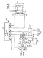
- FIG. 1 shows a turning axis XX axis comprising a bench 1, a fixed headstock 2 and a movable headstock 3.
- the mandrel 4 of the fixed headstock has a shape 5 which in the example shown is frustoconical, any other form which can of course be used depending on the parts to be manufactured.
- a tool 6 consisting of a wheel cooperates with the shape 5 to gradually apply the material of a blank of metal (not shown) against the form 5, the blank being clamped between the tip 7 of the movable headstock 3 and the corresponding end face of the form 5.
- the thumbwheel 6 can execute movements in two directions a and b which, in the case shown are perpendicular to each other, the direction b being approximately parallel to the mean generatrix of the form 5.
- the wheel is rotatably mounted on a support 8 carried by a carriage 9 slidably mounted on a slide 10 secured to the bench 1 of the lathe ( Figure 3).
- the carriage 9 itself constitutes a slide 11 on which a second carriage can move, the latter carrying out the movements of the tool in direction b.
- the movements of the carriage 9 in the direction a are controlled by a jack (not shown), while the movements of the carriage 12 are controlled by a jack 13 whose cylinder 14, of axis YY, oriented in the direction b receives a piston to which is attached a rod 15 integral with the carriage 12 near the support 8.
- the construction of the support 8 is clearly shown in FIG. 2. It comprises a fixing plate 16 provided with arcuate buttonholes 17 through which pass fixing screws 18 (not shown in FIG. 2), this arrangement thus allowing adjustment of the 'attitude of the dial 6 with respect to the axis XX of the lathe.
- a bracket 19 is secured to the fixing plate 16 and carries a yoke 20 which is secured to the bracket only by its upper edge thus leaving between it and the bracket a space 21 in which are housed two force sensors 22 placed at the same height near the vertical edges of the core of the yoke 20.
- the dial 6 is rotatably mounted in the yoke 20.
- FIG. 4 shows an example of a setpoint generator 23 for manual operation of the lathe.
- This generator comprises a housing in which is housed a potentiometer 24.
- the cursor 25 thereof is secured to a slide 26 with an actuation button mounted on a rod 27 which can slide in the housing. From its zero position (position in FIG. 4), the slide 26 can be moved to the position of maximum force against the action of a helical spring 28 surrounding the rod 27, this spring giving the operator has a feeling of increased effort on the wheel as he brings the cursor to the maximum position (on the left in Figure 4).
- the cursor 25 can also be brought to the rear to cause the wheel carriage 12 to retract, the rod 27 being moved to the right in FIG. 4 by sliding in its supports.
- the generator 23 described and shown is only an example, the same function can be fulfilled by any other suitable analog control member.
- the setpoint generator 23 is associated with an electronic storage and control circuit 29 (FIG. 5) which can replace it when the lap is set to automatic mode.
- FIG. 5 represents the simplified diagram of the control loop 30 used in the lathe according to the invention.
- the generator 23 as well as the storage and control circuit 29 are connected to the first input 31 of a differential amplifier 32 which can be of a conventional design, by means of a switch 33 for selecting operating modes.
- the second input 34 of the amplifier 32 is connected to a summing preamplifier 35 connected to the force sensors 22 ( Figures 2 and 3).
- the potentiometer 24 is supplied from the terminals 36 of the amplifier 32, while its cursor 25 is connected to a first fixed terminal 33a of the selector 33.
- the second and third terminals 33b and 33c of this same selector are connected to the intermediate sockets respective of a voltage divider composed of three resistors 37a, 37b and 37c and intended to fix the range of force adjustment (coarse, medium, fine) in manual operating mode.
- the fourth fixed terminal 33d of the selector is connected to the output of the memory and control circuit 29.
- the mobile terminal 33e of the selector is connected to the input 31 of the amplifier 32 and also to the storage input 38 of the circuit 29.
- the power output 39, 40 of the amplifier 32 is connected to. control coils 41 and 42 of a controlled solenoid valve 43 through which the jack 13 is supplied with a flow rate and the direction of flow of the fluid determined as a function of the signals applied to the differential amplifier 32.
- the servo loop is balanced when the thrust exerted by the wheel corresponds to the chosen position of this slider 26.
- the setpoint signal requested by the generator 23 is transformed into a corresponding thrust of the dial on the workpiece, the work of the operator being facilitated by the fact that the generator 23 supplies it by the spring 27 the sensation of carrying out the pushing itself on the thumbwheel to a considerable amplification coefficient, of course. It is especially essential to note that the measurement made by the sensors 22 does not take into account all the parasitic forces which are generated at the level of the slide 11 of the carriage carrying the support 8 so that the precision of this measurement is very high.
- the circuit 29 is connected by its output to the terminal 33d of the selector 33 by means of which it can be connected to the reference input 31 of the differential amplifier 32.
- the storage circuit 29 and control can be achieved in different ways.
- it can be constituted by a microprocessor suitably programmed to act on the control loop 30 and also and advantageously to execute other functions of the lathe such as for example the control of the longitudinal movement of the thumb wheel, the control of the lathe drive motor, actuation of the headstock, control of certain parameters, etc.
- the invention is not limited to the embodiment described above.
- a servo loop similar to that used for the transverse movement of the thumbwheel can be used for the longitudinal movement.
- relay and potentiometer assemblies supplying setpoint signals to the amplifier 30 in a given order according to a pre-established program.
- the lathe according to the invention making it possible to very precisely adjust and control the working effort of the wheel 6 in several ranges adjustment from zero force up to the maximum value foreseen in the selected range.
- materials with very varied hardnesses such as stainless steel, carbon steel, aluminum, etc., and also with very varied thicknesses .
Landscapes
- Engineering & Computer Science (AREA)
- Mechanical Engineering (AREA)
- Physics & Mathematics (AREA)
- General Physics & Mathematics (AREA)
- Automation & Control Theory (AREA)
- Turning (AREA)
- Automatic Control Of Machine Tools (AREA)
- Shaping Metal By Deep-Drawing, Or The Like (AREA)
Description
La présente invention concerne la technique du repoussage ou du fluotournage consistant à obtenir des objets de révolution en plaquant un flan de métal sur une pièce de forme maintenue en rotation et présentant le profil intérieur de l'objet intérieur de l'objet à fabriquer.The present invention relates to the technique of spinning or flow spinning consisting in obtaining objects of revolution by pressing a metal blank on a shaped part kept in rotation and having the internal profile of the internal object of the object to be manufactured.
La mise en oeuvre de cette technique est réalisée sur des tours comportant un outil de travail qui est monté sur un chariot pouvant se déplacer selon deux mouvements perpendiculaires et qui en étant appuyé contre le métal du flan assure progressivement, généralement en plusieurs passes, l'obtention de la forme correcte de l'objet. Le mouvement longitudinal du chariot, c'est-à-dire celui qui travaille généralement parallèlement à la génératrice moyenne du mandrin rotatif est en général obtenu par un moteur hydraulique à vis et écrou ou analogue qui entraîne une coulisse double sur laquelle est montée la coulisse porte-molette. Celle-ci se déplace selon un mouvement transversal à la génératrice moyenne du mandrin rotatif et est provoqué généralement par un vérin hydraulique ou analogue.The implementation of this technique is carried out on lathes comprising a working tool which is mounted on a carriage which can move in two perpendicular movements and which, being pressed against the metal of the blank, gradually ensures, generally in several passes, the obtaining the correct shape of the object. The longitudinal movement of the carriage, that is to say that which generally works parallel to the medium generator of the rotary mandrel is generally obtained by a hydraulic motor with screw and nut or the like which drives a double slide on which the slide is mounted wheel holder. This moves in a movement transverse to the average generator of the rotary mandrel and is generally caused by a hydraulic cylinder or the like.
Dans un premier type de tours antérieurs, ce vérin hydraulique de mouvement transversal est régulé en pression par l'intermédiaire d'une soupape de décharge connectée à l'orifice de poussée du vérin hydraulique.In a first type of previous turns, this hydraulic cylinder of transverse movement is regulated in pressure by means of a relief valve connected to the thrust orifice of the hydraulic cylinder.
Un tel tour présente des inconvénients qui sont liés au fait qu'il n'est pas possible de régler l'effort de poussée de la molette sur le métal en dessous d'une certaine limite définie par la valeur inférieure de la plage de tarage de la soupape de décharge. De plus, il faut tenir compte des frottements mécaniques de la coulisse porte-molette et de son vérin. Sur un tel tour, on peut donc difficilement travailler sur des métaux tendres, effectuer des finitions sur ces métaux, ou travailler sur des pièces minces, opérations pour lesquelles la poussée doit nécessairement être très faible. Bien entendu, il serait possible de modifier la plage de réglage de pression en changeant la soupape de décharge ou le ressort de tarage de celle-ci, mais on comprend qu'une telle mesure ne contribue pas à un maniement commode du tour.Such a turn has drawbacks which are linked to the fact that it is not possible to adjust the pushing force of the wheel on the metal below a certain limit defined by the lower value of the setting range of the relief valve. In addition, it is necessary to take into account the mechanical friction of the thumbwheel slide and its jack. On such a lathe, it is therefore difficult to work on soft metals, to carry out finishes on these metals, or to work on thin parts, operations for which the thrust must necessarily be very low. Of course, it would be possible to modify the pressure adjustment range by changing the relief valve or the calibration spring thereof, but it is understood that such a measurement does not contribute to a convenient handling of the lathe.
Un autre type de tour utilisant un dispositif de copiage tel que celui décrit dans FR-A-2 416 767 apporte un perfectionnement au tour décrit ci-dessus grâce au fait que le vérin qui assure la poussée de la molette est commandé par une vanne asservie au profil d'un gabarit pour pouvoir déterminer le trajet de la molette au cours de plusieurs passes successives nécessaires pour obtenir l'objet. Ce document a servi de base pour l'élaboration du préambule des revendications 1 et 2.Another type of lathe using a copying device such as that described in FR-A-2 416 767 brings an improvement to the lathe described above thanks to the fact that the jack which ensures the thrust of the thumb wheel is controlled by a servo valve to the profile of a template to be able to determine the path of the wheel during several successive passes necessary to obtain the object. This document served as the basis for the preparation of the preamble of
Plus précisément, le gabarit est exploré par un palpeur qui actionne un capteur de mouvement dont le signal de sortie est envoyé sur une première entrée d'un amplificateur différentiel formant l'organe central de la boucle d'asservissement. La deuxième entrée de l'amplificateur reçoit un signal de consigne engendré par un générateur de signaux de consigne commutables correspondant chacun à une passe ou une série de passes de la molette. L'amplificateur envoie un signal de commande à la vanne asservie lorsqu'il est mis en état de déséquilibre par la variation du signal provenant du capteur.More precisely, the template is explored by a probe which actuates a motion sensor, the output signal of which is sent to a first input of a differential amplifier forming the central organ of the servo loop. The second input of the amplifier receives a setpoint signal generated by a generator of switchable setpoint signals each corresponding to one pass or a series of passes of the dial. The amplifier sends a control signal to the slave valve when it is put in an imbalance state by the variation of the signal coming from the sensor.
Bien que ce dispositif de commande fonctionne de façon satisfaisante, il est néanmoins nécessaire pour les passes de finition avec un métal tendre de prévoir une suspension élastique de la molette sur son chariot. Par ailleurs, il est nécessaire de fabriquer avec une grande précision des gabarits mécaniques pour tous les objets à fabriquer que l'on doit monter sur la machine dont l'usage est donc peu souple.Although this control device functions satisfactorily, it is nevertheless necessary for the finishing passes with a soft metal to provide an elastic suspension of the wheel on its carriage. Furthermore, it is necessary to manufacture with great precision mechanical jigs for all the objects to be manufactured which must be mounted on the machine, the use of which is therefore not very flexible.
On connaît également d'après FR-A-2 217 741 une commande de dispositif asservi. Ce document décrit un procédé d'enregistrement d'un programme de travail d'un dispositif asservi pour imiter les mouvements exécutés par l'opérateur de la machine, le programme étant mis en mémoire une fois pour toutes par l'exécution des opérations par l'opérateur lui-même. A cet effet, le procédé met en couvre un vérin de travail qui est déplacé manuellement pendant l'opération d'enregistrement du programme conformément à une séquence désirée de mouvements devant être répétés dans le processus de travail automatique que doit exécuter la machine. Ce procédé n'est pas applicable au repoussagelfluotournage, car il serait impossibie à un opérateur de fournir manuellement l'énergie destinée à appliquer l'outil sur l'ébauche à déformer.Also known from FR-A-2 217 741 is a command for a slave device. This document describes a method of recording a work program of a servo device to imitate the movements executed by the operator of the machine, the program being stored once and for all by the execution of operations by the operator himself. To this end, the method covers a working cylinder which is moved manually during the program recording operation in accordance with a desired sequence of movements to be repeated in the automatic working process to be performed by the machine. This process is not applicable to spinning, since it would be impossible for an operator to manually supply the energy intended to apply the tool to the blank to be deformed.
Le DE-A-2 457 504 décrit une machine de fabrication de tubes cylindriques à section circulaire, à partir d'ébauches d'épaisseur relativement grande. A cet effet, l'ébauche montée sur un mandrin mobile en direction axiale de celle-ci est déplacée selon cette direction par rapport à un galet fixe formant outil, ce galet, en mordant dans l'épaisseur de l'ébauche, déformant celle-ci dans le sens de l'allongement.DE-A-2 457 504 describes a machine for manufacturing cylindrical tubes with circular section, from blanks of relatively large thickness. To this end, the blank mounted on a movable mandrel in the axial direction thereof is moved in this direction relative to a fixed roller forming a tool, this roller, by biting into the thickness of the blank, deforming it. Ci in the direction of elongation.
L'avance du mandrin supportant l'ébauche est effectuée par un vérin dont l'effort, c'est-à-dire la pression d'actionnement, est asservi à une pression de référence fournie par un capteur différentiel. Le signal d'erreur engendré dans ce capteur est appliqué à un amplificateur qui régule soit la pression du vérin, soit la vitesse de rotation du mandrin. On tente ainsi d'obtenir une compensation des variations de dureté locales pouvant se présenter dans les ébauches.The advancement of the mandrel supporting the blank is effected by a jack whose effort, that is to say the actuation pressure, is controlled by a reference pressure supplied by a differential sensor. The error signal generated in this sensor is applied to an amplifier which regulates either the cylinder pressure or the speed of rotation of the mandrel. An attempt is therefore made to obtain compensation for variations in local hardness which may occur in the blanks.
Toutefois, cette compensation n'est que partiellement réalisée puisque la capsule de mesure du capteur différentiel en mesurant la pression dans la chambre du vérin détecte non seulement l'effort exercé par l'outil, mais également tous les efforts secondaires dus aux frottements et autres phénomènes parasites que le vérin doit vaincre et dont les grandeurs sont loin d'être négligeables, compte tenu des efforts considérables engendrés par le fluotournage. Ces efforts parasites ne sont pas constants et ont de plus une composante transversale importante qui se répercute sur les coussinets dans lesquels se déplace le mandrin.However, this compensation is only partially achieved since the differential sensor measuring capsule by measuring the pressure in the cylinder chamber not only detects the force exerted by the tool, but also all the secondary forces due to friction and the like. parasitic phenomena which the jack must overcome and whose magnitudes are far from negligible, taking into account the considerable efforts generated by flow turning. These parasitic forces are not constant and moreover have a significant transverse component which affects the bearings in which the mandrel moves.
Il est donc clair qu'à l'aide de l'enseignement du DE-A-2 457 504, on ne peut atteindre l'objectif qui est à la base de l'invention, à savoir de fournir une machine de repoussage/fluotournage pouvant être manoeuvrée avec une grande précision aussi bien pour les passes de travail que pour les passes de finition, sans manipulations compliquées tout en étant par ailleurs facilement adaptable à une commande entièrement automatique pour l'exécution de pièces en série.It is therefore clear that with the aid of the teaching of DE-A-2 457 504, it is not possible to achieve the objective which is the basis of the invention, namely to provide a push-back / flow-spin machine. can be maneuvered with great precision for both work passes and finishing passes, without complicated handling while also being easily adaptable to a fully automatic control for the execution of parts in series.
Un des objets de l'invention consiste en une machine de repoussage/fluotournage comportant un dispositif de mise en rotation d'un mandrin autour d'un axe horizontal, ce mandrin présentant le profil intérieur de la pièce à obtenir et étant destiné à coopérer avec un outil de travail qui est monté sur un chariot capable d'effectuer deux mouvements perpendiculaires entre eux, au moins le mouvement à peu près transversal de l'outil par rapport à la génératrice moyenne du mandrin étant commandé par une boucle d'asservissement reliée à l'organe de commande du dispositif moteur assurant ce mouvement transversal, ladite boucle d'asservissement comportant en tant que générateur de signal réel ou instantané au moins un capteur sensible à l'effort exercé par l'outil sur l'objet en cours de formage ainsi qu'un générateur de consigne représentant l'effort à exercer par l'outil, ladite machine étant caractérisée en ce que ledit capteur est monté dans le support même de l'outil et sensible aux déformations de ce support à l'effort exercé par l'outil et en ce que ledit générateur de consigne comporte des moyens pour faire varier de façon dynamique le signal de consigne au cours de chaque passe de travail de l'outil, constitués par un dispositif à actionnement manuel variable en continu.One of the objects of the invention consists of a spinning / flow spinning machine comprising a device for rotating a mandrel around a horizontal axis, this mandrel having the internal profile of the part to be obtained and being intended to cooperate with a working tool which is mounted on a carriage capable of carrying out two perpendicular movements between them, at least the roughly transverse movement of the tool relative to the average generator of the mandrel being controlled by a servo loop connected to the control member of the motor device ensuring this transverse movement, said control loop comprising as a real or instantaneous signal generator at least one sensor sensitive to the force exerted by the tool on the object being formed as well as a setpoint generator representing the force to be exerted by the tool, said machine being characterized in that said sensor is mounted in the very support of the tool and sensitive to deformation ations of this support to the force exerted by the tool and in that said setpoint generator comprises means for dynamically varying the setpoint signal during each working pass of the tool, constituted by a device with continuously variable manual actuation.
Un autre objet de l'invention consiste en une machine pour le repoussage/fluotournage comportant un dispositif de mise en rotation d'un mandrin autour d'un axe horizontal, ce mandrin présentant le profil intérieur de la pièce à obtenir et étant destiné à coopérer avec un outil de travail qui est monté sur un chariot capable d'effectuer deux mouvements perpendiculaires entre eux, au moins le mouvement à peu près transversal de l'outil par rapport à la génératrice moyenne du mandrin étant commandé par une boucle d'asservissement reliée à l'organe de commande du dispositif moteur assurant ce mouvement transversal, ladite boucle d'asservissement comportant en tant que générateur de signal réel ou instantané au moins un capteur sensible à l'effort exercé par l'outil sur l'objet en cours de formage ainsi qu'un générateur de consigne représentant l'effort à exercer par l'outil, ladite machine étant caractérisée en ce que ledit capteur est monté dans le support même de l'outil et sensible aux déformations de ce support dues à l'effort exercé par l'outil et en ce que ledit générateur de consigne comporte des moyens pour faire varier de façon dynamique le signal de consigne au cours de chaque passe de travail de l'outil, constitués par un circuit de mémorisation et de commande dans lequel sont mémorisés des signaux de consigne destinés à être sélectivement appliqués à ladite boucle d'asservissement.Another object of the invention consists of a machine for pushing back / spinning comprising a device for rotating a mandrel around a horizontal axis, this mandrel having the internal profile of the part to be obtained and being intended to cooperate with a working tool which is mounted on a carriage capable of carrying out two perpendicular movements with one another, at least the roughly transverse movement of the tool relative to the mean generator of the mandrel being controlled by a connected servo loop to the control device of the motor device ensuring this transverse movement, said control loop comprising as real or instantaneous signal generator at least one sensor sensitive to the force exerted by the tool on the object being forming as well as a setpoint generator representing the force to be exerted by the tool, said machine being characterized in that said sensor is mounted in the very support of the tool and sensitive to deformations of this support due to the force exerted by the tool and in that said setpoint generator comprises means for dynamically varying the setpoint signal during each working pass of the tool, constituted by a memory and control circuit in which reference signals are memorized intended to be selectively applied to said control loop.
Grâce à ces caractéristiques, la boucle d'asservissement ne reçoit, en tant que signal réel, que l'effort réellement exercé sur l'objet en cours de formage, car tous les efforts parasites engendrés sur la mécanique couplant le vérin d'actionnement au support d'outil ne sont pas pris en compte. Il en résulte une précision de commande très élevée. Par ailleurs, le signal de consigne étant variable de façon dynamique, il devient possible de doser avec cette très grande précision l'effort de l'outil dans une plage allant d'une valeur nulle à la valeur maximale d'effort de l'outil pouvant être fournie par la machine, la boucle d'asservissement tendant à chaque instant à annuler le signal d'erreur résultant de la comparaison du signal de consigne et du signal réel et ce quelle que soit la valeur absolue de l'effort choisi au niveau du générateur de consigne. Ainsi, la plage de réglage peut aller de 0 à 2 000 kg par exemple.Thanks to these characteristics, the control loop receives, as a real signal, only the force actually exerted on the object being formed, since all the parasitic forces generated on the mechanics coupling the actuating cylinder to the tool holder are not taken into account. This results in very high control accuracy. Furthermore, the setpoint signal being dynamically variable, it becomes possible to measure with this very high precision the force of the tool in a range from a zero value to the maximum value of force of the tool. can be supplied by the machine, the control loop tending at all times to cancel the error signal resulting from the comparison of the setpoint signal and the actual signal, regardless of the absolute value of the force chosen at the level of the setpoint generator. Thus, the adjustment range can range from 0 to 2,000 kg for example.
L'invention permet également avec une grande souplesse de fonctionnement d'obtenir la possibilité de recopier des séries de pièces identiques, en faisant passer la machine tout d'abord par une phase manuelle dite « d'apprentissage au cours de laquelle le générateur de consigne est commandé par l'opérateur pendant que les consignes sont mémorisées, après quoi la machine est capable de restituer elle-même ces valeurs au cours d'une phase de recopie pendant laquelle les pièces sont fabriquées en série.The invention also makes it possible, with great operating flexibility, to obtain the possibility of copying series of identical parts, by first passing the machine through a manual phase known as "learning during which the setpoint generator is controlled by the operator while the setpoints are stored, after which the machine is able to restore these values itself during a copying phase during which the parts are produced in series.
L'invention est exposée ci-après plus en détail à l'aide de dessins représentant seulement un mode d'exécution, sur lesquels :
- la figure 1 est une vue en perspective schématique d'un tour de repoussage suivant l'invention vue du côté arrière ;
- la figure 2 représente une vue à plus grande échelle, d'un support de molette pour le tour de la figure 1 conçu suivant l'invention ;
- la figure 3 représente une vue en élévation latérale de ce support et de la molette ;
- la figure 4 est une vue en élévation et en coupe d'un boîtier de commande manuelle pouvant être utilisé avec le tour de l'invention ; et
- la figure 5 est un schéma simplifié de la boucle d'asservissement utilisée dans le tour de la figure 1.
- Figure 1 is a schematic perspective view of a spinning lathe according to the invention seen from the rear side;
- 2 shows a view on a larger scale of a wheel support for the lathe of Figure 1 designed according to the invention;
- Figure 3 shows a side elevational view of this support and the wheel;
- Figure 4 is an elevational and sectional view of a manual control unit that can be used with the lathe of the invention; and
- FIG. 5 is a simplified diagram of the control loop used in the lathe of FIG. 1.
On a représenté sur la figure 1 un tour de repoussage d'axe X-X comprenant un banc 1, une poupée fixe 2 et une poupée mobile 3. Le mandrin 4 de la poupée fixe porte une forme 5 qui dans l'exemple représenté est tronconique, toute autre former pouvant bien entendu être utilisée en fonction des pièces à fabriquer. Un outil 6 constitué par une molette coopère avec la forme 5 pour appliquer progressivement le matériau d'un flan de métal (non représenté) contre la forme 5, le flan étant serré entre la pointe 7 de la poupée mobile 3 et la face d'extrémité correspondante de la forme 5.FIG. 1 shows a turning axis XX axis comprising a bench 1, a
La molette 6 peut exécuter des mouvements selon deux directions a et b qui, dans le cas représenté sont perpendiculaires entre elles, la direction b étant à peu près parallèle à la génératrice moyenne de la forme 5.The
A cet effet, la molette est montée à rotation sur un support 8 porté par un chariot 9 monté coulissant sur une glissière 10 solidaire du banc 1 du tour (figure 3). Le chariot 9 constitue lui-même une glissière 11 sur laquelle peut se déplacer un second chariot, ce dernier exécutant les mouvements de l'outil selon la direction b.To this end, the wheel is rotatably mounted on a
Les mouvements du chariot 9 suivant la direction a sont commandés par un vérin (non représenté), tandis que les mouvements du chariot 12 sont commandés par un vérin 13 dont le cylindre 14, d'axe Y-Y, orienté selon la direction b reçoit un piston auquel est attachée une tige 15 solidaire du chariot 12 près du support 8.The movements of the
La construction du support 8 apparaît clairement sur la figure 2. Il comporte une plaque de fixation 16 munie de boutonnières arquées 17 à travers lesquelles passent des vis de fixation 18 (non représentées sur la figure 2), cet agencement permettant ainsi un ajustement de l'attitude de la molette 6 par rapport à l'axe X-X du tour.The construction of the
Une potence 19 est solidaire de la plaque de fixation 16 et porte une chape 20 qui n'est solidaire de la potence que par son bord supérieur laissant ainsi subsister entre elle et la potence un espace 21 dans lequel sont logés deux capteurs d'effort 22 placés à la même hauteur près des bords verticaux de l'âme de la chape 20. La molette 6 est montée rotative dans la chape 20.A
La figure 4 montre un exemple d'un générateur de consigne 23 pour le fonctionnement manuel du tour. Ce générateur comporte un boîtier dans lequel est logé un potentiomètre 24. Le curseur 25 de celui-ci est solidaire d'un coulisseau 26 à bouton d'actionnement monté sur une tige 27 pouvant coulisser dans le boîtier. A partir de sa position zéro (position de la figure 4), le coulisseau 26 peut être déplacé vers la position d'effort maximal à l'encontre de l'action d'un ressort hélicoïdal 28 entourant la tige 27, ce ressort donnant à l'opérateur une sensation d'augmentation de l'effort sur la molette au fur et à mesure qu'il amène le curseur vers la position maximale (à gauche sur la figure 4). Le curseur 25 peut également être amené vers l'arrière pour provoquer le recul du chariot porte-molette 12, la tige 27 étant déplacée vers la droite de la figure 4 en coulissant dans ses supports. Bien entendu, le générateur 23 décrit et représenté n'est qu'un exemple, la même fonction pouvant être remplie par tout autre organe de commande analogue approprié.Figure 4 shows an example of a
Le générateur de consigne 23 est associé à un circuit électronique de mémorisation et de commande 29 (figure 5) qui peut le remplacer lorsque le tour est réglé sur le mode automatique.The
La figure 5 représente le schéma simplifié de la boucle d'asservissement 30 utilisée dans le tour suivant l'invention.FIG. 5 represents the simplified diagram of the
Le générateur 23 ainsi que le circuit 29 de mémorisation et de commande sont connectés à la première entrée 31 d'un amplificateur différentiel 32 qui peut être d'une conception classique, par l'intermédiaire d'un commutateur 33 sélecteur de modes de fonctionnement. La seconde entrée 34 de l'amplificateur 32 est reliée à un préamplificateur sommateur 35 connecté aux capteurs d'effort 22 (figures 2 et 3). Le potentiomètre 24 est alimenté à partir des bornes 36 de l'amplificateur 32, tandis que son curseur 25 est connecté à une première borne 33a fixe du sélecteur 33. Les seconde et troisième bornes 33b et 33c de ce même sélecteur sont reliées aux prises intermédiaires respectives d'un diviseur de tension composé de trois résistances 37a, 37b et 37c et destiné à fixer la plage de réglage d'effort (grossière, moyenne, fine) en mode de fonctionnement manuel. La quatrième borne fixe 33d du sélecteur est reliée à la sortie du circuit 29 de mémorisation et de commande.The
La borne mobile 33e du sélecteur est connectée à l'entrée 31 de l'amplificateur 32 et également à l'entrée de mémorisation 38 du circuit 29.The
La sortie de puissance 39, 40 de l'amplificateur 32 est reliée aux. bobines de commande 41 et 42 d'une électro-vanne asservie 43 à travers laquelle est alimenté le vérin 13 avec un débit et le sens d'écoulement du fluide déterminés en fonction des signaux appliqués sur l'amplificateur différentiel 32.The
Le fonctionnement du tour que l'on vient de décrire est le suivant.The operation of the tour which has just been described is as follows.
Au début, le coulisseau 25 est amené vers l'arrière (vers la droite sur la figure 4), la tige 27 étant également dans sa position reculée sans que le ressort 28 puisse la déplacer vers l'avant. Le coulisseau 25 reste donc pour le moment dans la position arrière. Dans ces conditions, une tension positive maximale est appliquée à la boucle d'asservissement et de ce fait le chariot 12 se trouve en position reculée contre ses butées mécaniques (non représentées).At the start, the
Après montage d'une forme et d'un flan sur le tour, il suffit d'avancer le curseur 25 vers la position zéro (en déplaçant le coulisseau 26 vers la gauche sur la figure 4) puis en continuant, le vérin 13 est alimenté pour déplacer le chariot 12 vers l'avant. En effet, dans ces conditions, la molette 6 ne se voyant opposer aucune résistance à la progression transversale selon la flèche b (figure 1), les capteurs 22 ne fournissent pas encore de signal et l'amplificateur 32 produit un signal de différence dont la valeur dépend de la distance sur laquelle le coulisseau 26 a été déplacé, valeur qui en définitive commande le débit dans le vérin 13 et donc la vitesse de déplacement de la molette 6, par l'intermédiaire de la vanne asservie 43.After mounting a shape and a blank on the lathe, it is enough to advance the
Dès que la molette 6 rencontre une résistance par sa mise en contact avec le flan à travailler, il se produit une très légère déformation de l'âme de la chape 20, ce qui se traduit par la production d'un signal d'effort ou de poussée instantané sur la borne de sortie de l'amplificateur sommateur 35, signal qui est engendré par les capteurs 22. Ceux-ci délivrent une information en pico-Coulomb qui est transformée en une tension variant dans une plage de 0 à 10 V par exemple, à la sortie de l'amplificateur 35, en fonction de la résistance rencontrée par la molette 6.As soon as the
Si l'opérateur ne déplace pas le coulisseau 26, un équilibre de la boucle d'asservissement est atteint lorsque la poussée exercée par la molette correspond à la position choisie de ce coulisseau 26.If the operator does not move the
Par contre, si l'opérateur avance ce dernier davantage, la boucle est de nouveau déséquilibrée et le système cherche un nouvel état d'équilibre moyennant une poussée plus forte de la molette 6 sur la pièce. Bien entendu, simultanément, l'opérateur peut provoquer le déplacement longitudinal de la molette selon la flèche a.On the other hand, if the operator advances the latter further, the loop is again unbalanced and the system searches for a new state of equilibrium by means of a stronger push of the
On constate donc qu'à tout instant, le signal de consigne demandé par le générateur 23 est transformé en une poussée correspondante de la molette sur la pièce à former, le travail de l'opérateur étant facilité par le fait que le générateur 23 lui fournit par le ressort 27 la sensation d'effectuer lui-même la poussée sur la molette à un coefficient d'amplification considérable près, bien entendu. Il est surtout essentiel de noter que la mesure effectuée par les capteurs 22 ne tient nullement compte de tous les efforts parasites qui sont engendrés au niveau du coulisseau 11 du chariot portant le support 8 de sorte que la précision de cette mesure est très élevée.It is therefore found that at all times, the setpoint signal requested by the
Le fonctionnement manuel que l'on vient de décrire peut être utilisé pour une ou plusieurs pièces à fabriquer, mais conformément à l'invention, il est également possible de mémoriser toutes les valeurs de consigne engendrées au cours d'un cycle de travail donné dans le circuit 29 de mémorisation et de commande pour ensuite restituer ces valeurs pour la fabrication ultérieure de pièces identiques.The manual operation which has just been described can be used for one or more parts to be manufactured, but in accordance with the invention, it is also possible to store all the set values generated during a given work cycle in the circuit 29 for memorization and control to then restore these values for the subsequent manufacture of identical parts.
C'est à cet effet que le circuit 29 est connecté par sa sortie à la borne 33d du sélecteur 33 par l'intermédiaire duquel il peut être branché sur l'entrée de consigne 31 de l'amplificateur différentiel 32. Le circuit 29 de mémorisation et de commande peut être réalisé de différentes façons. Par exemple et avantageusement, il peut être constitué par un microprocesseur convenablement programmé pour agir sur la boucle d'asservissement 30 et également et avantageusement pour exécuter d'autres fonctions du tour telles que par exemple la commande du mouvement longitudinal de la molette, la commande du moteur d'entraînement du tour, l'actionnement de la poupée mobile, le contrôle de certains paramètres, etc.It is for this purpose that the circuit 29 is connected by its output to the terminal 33d of the
Au cours du fonctionnement manuel, l'opérateur peut choisir plusieurs gammes de poussées allant de 0 kg à une valeur de poussée maximale. A titre d'exemple et pour fixer les idées seulement, les trois premières positions du sélecteur 33. peuvent correspondre aux plages de réglage suivantes :
- - borne 33a : 0 à 2 000 kg
- - borne 33b : 0 à 1 320 kg
- - borne 33c : 0 à 666 kg
- -
terminal 33a: 0 to 2,000 kg - - terminal 33b: 0 to 1 320 kg
- -
terminal 33c: 0 to 666 kg
Bien entendu, l'invention n'est pas limitée au mode de réalisation décrit ci-dessus. Par exem; ple, une boucle d'asservissement analogue à celle utilisée pour le mouvement transversal de la molette peut être employée pour le mouvement longitudinal. Par ailleurs, pour la programmation du mode de fonctionnement automatique, il est possible d'utiliser des montages à relais et potentiomètres fournissant des signaux de consigne à l'amplificateur 30 dans un ordre donné en fonction d'un programme pré-établi.Of course, the invention is not limited to the embodiment described above. For example ; ple, a servo loop similar to that used for the transverse movement of the thumbwheel can be used for the longitudinal movement. Furthermore, for programming the automatic operating mode, it is possible to use relay and potentiometer assemblies supplying setpoint signals to the
On voit donc que grâce à l'invention, on élimine les inconvénients des dispositifs de repoussage de la technique antérieure, le tour suivant l'invention permettant de régler et de contrôler très précisément l'effort de travail de la molette 6 dans plusieurs plages de réglage à partir d'un effort nul jusqu'à la valeur maximale prévue dans la plage sélectionnée. Ainsi, on peut exécuter sur la même machine des travaux d'ébauchage et de finition sur des matériaux à duretés très variées, tels que l'acier inoxydable, l'acier au carbone, l'aluminium, etc, et à épaisseurs également très variées.It can therefore be seen that, thanks to the invention, the drawbacks of the pushing devices of the prior art are eliminated, the lathe according to the invention making it possible to very precisely adjust and control the working effort of the
En outre, aucun gabarit mécanique n'est nécessaire pour le fonctionnement en tour automatique.In addition, no mechanical jig is required for automatic lathe operation.
Enfin, bien que dans la description qui précède, on utilise une molette pour travailler les pièces, les spécialistes comprendront que l'on peut utiliser d'autres outils, tels que par exemple un « brunissoir », une boule ou autre.Finally, although in the above description, a wheel is used to work the parts, specialists will understand that one can use other tools, such as for example a "burnisher", a ball or the like.
Claims (6)
Applications Claiming Priority (2)
| Application Number | Priority Date | Filing Date | Title |
|---|---|---|---|
| FR8101383 | 1981-01-26 | ||
| FR8101383A FR2498493A1 (en) | 1981-01-26 | 1981-01-26 | IMPROVED REPELLENT TOWER |
Publications (3)
| Publication Number | Publication Date |
|---|---|
| EP0057136A2 EP0057136A2 (en) | 1982-08-04 |
| EP0057136A3 EP0057136A3 (en) | 1982-08-18 |
| EP0057136B1 true EP0057136B1 (en) | 1986-09-10 |
Family
ID=9254498
Family Applications (1)
| Application Number | Title | Priority Date | Filing Date |
|---|---|---|---|
| EP82400108A Expired EP0057136B1 (en) | 1981-01-26 | 1982-01-21 | Spinning apparatus |
Country Status (4)
| Country | Link |
|---|---|
| US (1) | US4509351A (en) |
| EP (1) | EP0057136B1 (en) |
| DE (1) | DE3273082D1 (en) |
| FR (1) | FR2498493A1 (en) |
Families Citing this family (22)
| Publication number | Priority date | Publication date | Assignee | Title |
|---|---|---|---|---|
| AT374706B (en) * | 1982-06-07 | 1984-05-25 | Haemmerle Ag | METAL BENDING METHOD AND BENDING DEVICE FOR EXERCISING THE METHOD |
| NL8301678A (en) * | 1983-05-11 | 1984-12-03 | Johan Massee | FORCING MACHINE. |
| US4870845A (en) * | 1986-05-02 | 1989-10-03 | Mitsubishi Jidosha Kogyo Kabushiki Kaisha | Working apparatus for crankshaft |
| FR2601603A1 (en) * | 1986-07-15 | 1988-01-22 | Aripa | Self-adapting folding-type bending method |
| DE3626495A1 (en) * | 1986-08-05 | 1988-02-18 | Kieserling & Albrecht | PRESSING MACHINE SUPPORT AND METHOD FOR OPERATING A PRESSING MACHINE |
| CH670404A5 (en) * | 1986-09-04 | 1989-06-15 | Alusuisse | |
| US4835826A (en) * | 1986-12-01 | 1989-06-06 | The B.F. Goodrich Company | Method of burnishing |
| DE3728313A1 (en) * | 1987-08-25 | 1989-03-16 | Man Technologie Gmbh | DEVICE FOR MEASURING THE RADIAL FORMING FORCE IN PRESSING ROLLING |
| EP0353427B1 (en) * | 1988-08-02 | 1992-11-11 | Wilhelm Hegenscheidt Gesellschaft mbH | Burnishing unit |
| US4976126A (en) * | 1989-08-02 | 1990-12-11 | Kabushiki Kaisha Yamamoto Kinzoku Seisakusho | Spinning machine |
| US4989434A (en) * | 1989-08-09 | 1991-02-05 | Adolph Coors Company | Method and apparatus for doming can bottoms |
| DE4040300A1 (en) * | 1990-12-17 | 1992-07-02 | Leifeld Gmbh & Co | PUSHING MACHINE WITH AT LEAST ONE ROLL HOLDER |
| GB9513705D0 (en) * | 1995-07-05 | 1995-09-06 | Spincraft Limited | Improvements in or relating to metal spinning |
| US6622570B1 (en) | 2000-03-01 | 2003-09-23 | Surface Technology Holdings Ltd. | Method for reducing tensile stress zones in the surface of a part |
| US6415486B1 (en) | 2000-03-01 | 2002-07-09 | Surface Technology Holdings, Ltd. | Method and apparatus for providing a residual stress distribution in the surface of a part |
| WO2002064560A1 (en) * | 2001-02-14 | 2002-08-22 | Asahi Kasei Kabushiki Kaisha | PROCESS FOR PREPARATION OF ε-CAPROLACTAM |
| WO2003039804A1 (en) * | 2001-11-02 | 2003-05-15 | The Boeing Company | Apparatus and method for forming weld joints having compressive residual stress patterns |
| WO2005056210A1 (en) * | 2003-12-08 | 2005-06-23 | National Institute Of Advanced Industrial Science And Technology | Method and device for spinning process |
| CN101549378B (en) * | 2009-05-13 | 2010-12-08 | 天津理工大学 | Hydraulic spin forming machine |
| JP4795462B2 (en) * | 2009-11-12 | 2011-10-19 | ファナック株式会社 | Roll hem processing equipment using robot manipulator with force sensor |
| CN102728690A (en) * | 2012-06-12 | 2012-10-17 | 西安航天动力机械厂 | End enclosure spinning backward-overturning preventing device |
| CN105081716A (en) * | 2015-09-16 | 2015-11-25 | 佛山市新恒萃材料科技有限公司 | Buffering type contact-force active-control multipurpose operation mechanism |
Family Cites Families (18)
| Publication number | Priority date | Publication date | Assignee | Title |
|---|---|---|---|---|
| GB716970A (en) * | 1951-09-01 | 1954-10-20 | James Cherry | Three dimensional dynamometer |
| US3145756A (en) * | 1961-09-19 | 1964-08-25 | Baldwin Lima Hamilton Corp | Numerically controlled tube bending machine |
| US3282078A (en) * | 1963-12-23 | 1966-11-01 | Cincinnati Milling Machine Co | Method of making grooved hollow article |
| US3564883A (en) * | 1968-07-30 | 1971-02-23 | Cincinnati Shaper Co | Hydraulic press control |
| US3596506A (en) * | 1969-03-25 | 1971-08-03 | Atomic Energy Commission | Tool force monitor |
| GB1325872A (en) * | 1969-07-23 | 1973-08-08 | Adamson Hatchett Ltd | Metal forming apparatus |
| DE2008204C3 (en) * | 1970-02-21 | 1974-06-12 | Tokyo Seimitsu Sokki K.K., Kanagawa (Japan) | Device for controlling multi-dimensional motion sequences |
| US3602090A (en) * | 1970-02-27 | 1971-08-31 | Boeing Co | Milling machine control system and milling force sensor therefor |
| US3726117A (en) * | 1971-06-07 | 1973-04-10 | Demag Ag | Device and method for controlling the movement of a deformation roll |
| FR2155400A5 (en) * | 1971-09-30 | 1973-05-18 | Licentia Gmbh | |
| NO131906C (en) * | 1973-02-13 | 1975-08-20 | Trallfa Nils Underhaug As | |
| IT1004663B (en) * | 1974-01-03 | 1976-07-20 | Caboni V | EQUIPMENT TO BE APPLIED TO A LATH TO PERFORM THE TURNING IN THE SHEET |
| DE2457504C3 (en) * | 1974-12-05 | 1983-04-21 | Messerschmitt-Bölkow-Blohm GmbH, 8000 München | Extrusion process and machine |
| JPS5218586A (en) * | 1975-08-05 | 1977-02-12 | Sumitomo Metal Ind Ltd | Manual control system |
| SU654318A1 (en) * | 1976-06-04 | 1979-03-30 | Предприятие П/Я В-2869 | Method of controlling the process of cold cross-rolling of tubes |
| NL172035C (en) * | 1977-09-19 | 1983-07-01 | Johan Massee | FORCING MACHINE. |
| CH630186A5 (en) * | 1979-06-28 | 1982-05-28 | Willemin Machines Sa | Method for producing an electronic program usable on the machine tool |
| GB2075389A (en) * | 1980-04-22 | 1981-11-18 | Bandwell Engineering Ltd | Lathe with hydraulic slide |
-
1981
- 1981-01-26 FR FR8101383A patent/FR2498493A1/en active Granted
-
1982
- 1982-01-21 DE DE8282400108T patent/DE3273082D1/en not_active Expired
- 1982-01-21 EP EP82400108A patent/EP0057136B1/en not_active Expired
- 1982-01-26 US US06/342,805 patent/US4509351A/en not_active Expired - Fee Related
Also Published As
| Publication number | Publication date |
|---|---|
| FR2498493B1 (en) | 1984-04-27 |
| DE3273082D1 (en) | 1986-10-16 |
| EP0057136A3 (en) | 1982-08-18 |
| FR2498493A1 (en) | 1982-07-30 |
| EP0057136A2 (en) | 1982-08-04 |
| US4509351A (en) | 1985-04-09 |
Similar Documents
| Publication | Publication Date | Title |
|---|---|---|
| EP0057136B1 (en) | Spinning apparatus | |
| FR2495505A1 (en) | BENDING METHOD AND APPARATUS FOR ADJUSTING THE RUN OF A BENDING PRESS | |
| FR2567058A1 (en) | DEVICE FOR A MACHINE TOOL, IN PARTICULAR A GRINDER, AND FOR MEASURING THE DIAMETER OF ECCENTRICALLY ROTATING WORKPIECES | |
| EP0227870A1 (en) | Automatically controlled machine for rolling metal sheets | |
| FR2682054A1 (en) | Inclination apparatus for a pivoting head with saddle (carriage) | |
| WO1997013614A1 (en) | Device for measuring or checking an orbitally mobile cylindrical part during machining thereof | |
| EP1872892A1 (en) | Method and installation for implementing spot welding electrodes | |
| FR2638118A1 (en) | METHOD AND APPARATUS FOR COMPRESSION AND CONTROL OF COMPRESSION OF PULVERULENT AND PRESSED MATERIALS BY APPLYING | |
| FR2703937A1 (en) | Device for applying a substantially constant force to a feed element of a machine tool. | |
| EP0168331B1 (en) | Machine for bending of tubes, bars or profiles | |
| CA1298120C (en) | Process for machining tubular workpieces, and device for applying said process | |
| EP0055648B1 (en) | Machine for work-pieces having a curved surface of a given shape | |
| BE1017060A3 (en) | ||
| CH666447A5 (en) | DEVICE FOR FOLDING THE LEGS OF A BOX CUT FROM THE BACK. | |
| EP0473739B1 (en) | Device for straightening a wire | |
| FR2476059A1 (en) | Glass sheet shaping machine - is controlled by a data processing unit instead of a cam | |
| EP0083518A1 (en) | Deep slitting machine for making grooved wheels for air tyres from non plane blanks | |
| FR2722439A1 (en) | METHOD AND DEVICE FOR MACHINING A WORKPIECE BY REMOVING OR DISCHARGE OF MATERIAL, AND WORKPIECES ACCORDING TO THIS PROCESS | |
| FR2466314A1 (en) | MACHINE FOR AFFECTING THE PINS | |
| WO1990000462A1 (en) | Honing device and process | |
| FR2597777A1 (en) | MACHINING DEVICE, IN PARTICULAR FOR A ROBOT APPLIED TO THE CARDING OF LEATHER | |
| FR2843710A1 (en) | OPHTHALMIC LENS GRINDING DEVICE AND METHOD | |
| CH365263A (en) | Reproduction device for lathe | |
| FR2466302A1 (en) | METHOD AND DEVICE FOR THE MACHINING OF FINISHED WHEELS | |
| FR2523493A1 (en) | Automatic part supply to machine tool - uses rotating turntable to transport parts under arm which picks up, turns and presents them |
Legal Events
| Date | Code | Title | Description |
|---|---|---|---|
| PUAI | Public reference made under article 153(3) epc to a published international application that has entered the european phase |
Free format text: ORIGINAL CODE: 0009012 |
|
| PUAL | Search report despatched |
Free format text: ORIGINAL CODE: 0009013 |
|
| AK | Designated contracting states |
Designated state(s): BE CH DE GB IT NL |
|
| AK | Designated contracting states |
Designated state(s): BE CH DE GB IT NL |
|
| 17P | Request for examination filed |
Effective date: 19830212 |
|
| GRAA | (expected) grant |
Free format text: ORIGINAL CODE: 0009210 |
|
| AK | Designated contracting states |
Kind code of ref document: B1 Designated state(s): BE CH DE GB IT LI NL |
|
| REF | Corresponds to: |
Ref document number: 3273082 Country of ref document: DE Date of ref document: 19861016 |
|
| ITF | It: translation for a ep patent filed |
Owner name: ING. C. GREGORJ S.P.A. |
|
| PLBI | Opposition filed |
Free format text: ORIGINAL CODE: 0009260 |
|
| 26 | Opposition filed |
Opponent name: SCHULZE HORN, S., DIPL.-ING. Effective date: 19870609 |
|
| NLR1 | Nl: opposition has been filed with the epo |
Opponent name: SCHULZE HORN,S.,DIPL.ING. |
|
| PLBN | Opposition rejected |
Free format text: ORIGINAL CODE: 0009273 |
|
| STAA | Information on the status of an ep patent application or granted ep patent |
Free format text: STATUS: OPPOSITION REJECTED |
|
| 27O | Opposition rejected |
Effective date: 19890623 |
|
| NLR2 | Nl: decision of opposition | ||
| PGFP | Annual fee paid to national office [announced via postgrant information from national office to epo] |
Ref country code: GB Payment date: 19920124 Year of fee payment: 11 |
|
| ITTA | It: last paid annual fee | ||
| PGFP | Annual fee paid to national office [announced via postgrant information from national office to epo] |
Ref country code: BE Payment date: 19920514 Year of fee payment: 11 |
|
| PGFP | Annual fee paid to national office [announced via postgrant information from national office to epo] |
Ref country code: CH Payment date: 19930120 Year of fee payment: 12 |
|
| PG25 | Lapsed in a contracting state [announced via postgrant information from national office to epo] |
Ref country code: GB Effective date: 19930121 |
|
| PG25 | Lapsed in a contracting state [announced via postgrant information from national office to epo] |
Ref country code: BE Effective date: 19930131 |
|
| PGFP | Annual fee paid to national office [announced via postgrant information from national office to epo] |
Ref country code: NL Payment date: 19930131 Year of fee payment: 12 |
|
| PGFP | Annual fee paid to national office [announced via postgrant information from national office to epo] |
Ref country code: DE Payment date: 19930209 Year of fee payment: 12 |
|
| BERE | Be: lapsed |
Owner name: ETS RONDOLOTTI Effective date: 19930131 |
|
| GBPC | Gb: european patent ceased through non-payment of renewal fee |
Effective date: 19930121 |
|
| PG25 | Lapsed in a contracting state [announced via postgrant information from national office to epo] |
Ref country code: LI Effective date: 19940131 Ref country code: CH Effective date: 19940131 |
|
| PG25 | Lapsed in a contracting state [announced via postgrant information from national office to epo] |
Ref country code: NL Effective date: 19940801 |
|
| NLV4 | Nl: lapsed or anulled due to non-payment of the annual fee | ||
| REG | Reference to a national code |
Ref country code: CH Ref legal event code: PL |
|
| PG25 | Lapsed in a contracting state [announced via postgrant information from national office to epo] |
Ref country code: DE Effective date: 19941001 |