DE102015114703B4 - Holding frame for connector modules - Google Patents
Holding frame for connector modules Download PDFInfo
- Publication number
- DE102015114703B4 DE102015114703B4 DE102015114703.3A DE102015114703A DE102015114703B4 DE 102015114703 B4 DE102015114703 B4 DE 102015114703B4 DE 102015114703 A DE102015114703 A DE 102015114703A DE 102015114703 B4 DE102015114703 B4 DE 102015114703B4
- Authority
- DE
- Germany
- Prior art keywords
- holding frame
- halves
- joint
- articulated
- press
- Prior art date
- Legal status (The legal status is an assumption and is not a legal conclusion. Google has not performed a legal analysis and makes no representation as to the accuracy of the status listed.)
- Expired - Fee Related
Links
Images

Classifications
-
- H—ELECTRICITY
- H01—ELECTRIC ELEMENTS
- H01R—ELECTRICALLY-CONDUCTIVE CONNECTIONS; STRUCTURAL ASSOCIATIONS OF A PLURALITY OF MUTUALLY-INSULATED ELECTRICAL CONNECTING ELEMENTS; COUPLING DEVICES; CURRENT COLLECTORS
- H01R13/00—Details of coupling devices of the kinds covered by groups H01R12/70 or H01R24/00 - H01R33/00
- H01R13/46—Bases; Cases
- H01R13/502—Bases; Cases composed of different pieces
- H01R13/504—Bases; Cases composed of different pieces different pieces being moulded, cemented, welded, e.g. ultrasonic, or swaged together
- H01R13/5045—Bases; Cases composed of different pieces different pieces being moulded, cemented, welded, e.g. ultrasonic, or swaged together different pieces being assembled by press-fit
-
- H—ELECTRICITY
- H01—ELECTRIC ELEMENTS
- H01R—ELECTRICALLY-CONDUCTIVE CONNECTIONS; STRUCTURAL ASSOCIATIONS OF A PLURALITY OF MUTUALLY-INSULATED ELECTRICAL CONNECTING ELEMENTS; COUPLING DEVICES; CURRENT COLLECTORS
- H01R13/00—Details of coupling devices of the kinds covered by groups H01R12/70 or H01R24/00 - H01R33/00
- H01R13/46—Bases; Cases
- H01R13/502—Bases; Cases composed of different pieces
- H01R13/506—Bases; Cases composed of different pieces assembled by snap action of the parts
-
- H—ELECTRICITY
- H01—ELECTRIC ELEMENTS
- H01R—ELECTRICALLY-CONDUCTIVE CONNECTIONS; STRUCTURAL ASSOCIATIONS OF A PLURALITY OF MUTUALLY-INSULATED ELECTRICAL CONNECTING ELEMENTS; COUPLING DEVICES; CURRENT COLLECTORS
- H01R13/00—Details of coupling devices of the kinds covered by groups H01R12/70 or H01R24/00 - H01R33/00
- H01R13/46—Bases; Cases
- H01R13/502—Bases; Cases composed of different pieces
- H01R13/508—Bases; Cases composed of different pieces assembled by a separate clip or spring
-
- H—ELECTRICITY
- H01—ELECTRIC ELEMENTS
- H01R—ELECTRICALLY-CONDUCTIVE CONNECTIONS; STRUCTURAL ASSOCIATIONS OF A PLURALITY OF MUTUALLY-INSULATED ELECTRICAL CONNECTING ELEMENTS; COUPLING DEVICES; CURRENT COLLECTORS
- H01R13/00—Details of coupling devices of the kinds covered by groups H01R12/70 or H01R24/00 - H01R33/00
- H01R13/46—Bases; Cases
- H01R13/516—Means for holding or embracing insulating body, e.g. casing, hoods
- H01R13/518—Means for holding or embracing insulating body, e.g. casing, hoods for holding or embracing several coupling parts, e.g. frames
-
- H—ELECTRICITY
- H01—ELECTRIC ELEMENTS
- H01R—ELECTRICALLY-CONDUCTIVE CONNECTIONS; STRUCTURAL ASSOCIATIONS OF A PLURALITY OF MUTUALLY-INSULATED ELECTRICAL CONNECTING ELEMENTS; COUPLING DEVICES; CURRENT COLLECTORS
- H01R13/00—Details of coupling devices of the kinds covered by groups H01R12/70 or H01R24/00 - H01R33/00
- H01R13/46—Bases; Cases
- H01R13/514—Bases; Cases composed as a modular blocks or assembly, i.e. composed of co-operating parts provided with contact members or holding contact members between them
Landscapes
- Connector Housings Or Holding Contact Members (AREA)
- Mutual Connection Of Rods And Tubes (AREA)
- Mirrors, Picture Frames, Photograph Stands, And Related Fastening Devices (AREA)
Abstract
Halterahmen (1), in welchen Steckverbindermodule (19) einsetzbar sind, wobei der Halterahmen (1) aus zwei miteinander verbindbaren Hälften (4, 5), einer ersten Hälfte (4) und einer zweiten Hälfte (5), besteht, wobei die Hälften (4, 5) in zumindest zwei Positionen zueinander ausrichtbar sind,
wobei die erste Hälfte (4) zumindest einen Gelenkkopf (2) aufweist und die zweite Hälfte (5) zumindest eine dazu passende Gelenkaufnahme (3) aufweist, wobei der Gelenkkopf (2) der ersten Hälfte (4) in die Gelenkaufnahme (3) der zweiten Hälfte (5) eingreifbar ist und dadurch eine gelenkige Verbindung der Hälften (4, 5) bereitgestellt ist,
wobei an dem Gelenkkopf (2) ein Gelenkarm (6) angeformt ist, wobei der Gelenkarm (6) mit der ersten Hälfte (4) verbunden ist dadurch gekennzeichnet,
- dass an dem Gelenkarm (6) eine Pressnase (7) angeformt ist
- dass die zweite Hälfte (5) an einer Stirnseite (11) zwei Mulden (9, 10) aufweist
- dass die Pressnase (7) in die zwei Mulden (9, 10) aufnehmbar ist,
- so dass die Hälften (4, 5) in zumindest zwei Positionen, eine offene Position und eine geschlossene Position, zueinander fixierbar sind.

wherein the first half (4) has at least one joint head (2) and the second half (5) has at least one matching joint holder (3), the joint head (2) of the first half (4) in the joint holder (3) of the second half (5) can be engaged and thereby an articulated connection of the halves (4, 5) is provided,
wherein an articulated arm (6) is formed on the articulated head (2), the articulated arm (6) being connected to the first half (4),
- That a press nose (7) is formed on the articulated arm (6)
- That the second half (5) on one end face (11) has two troughs (9, 10)
- That the press nose (7) can be received in the two troughs (9, 10),
- So that the halves (4, 5) can be fixed to each other in at least two positions, an open position and a closed position.
Description
Die Erfindung geht aus von einem Halterahmen für Steckverbindermodule nach dem Oberbegriff des unabhängigen Anspruchs 1.The invention relates to a holding frame for connector modules according to the preamble of
Derartige Halterahmen dienen zur Halterung von Steckverbindermodulen, wobei der Halterahmen mit verschiedenen Steckverbindermodulen bestückt und anschließend in ein Steckverbindergehäuse eingesetzt und mit diesem verschraubt wird. Dabei muss der Halterahmen mechanisch stabil sein, um den auftretenden Steck- und Ziehkräften beim Zusammenfügen bzw. Trennen der Steckverbindung standhalten zu können.Such holding frames are used to hold connector modules, the holding frame being equipped with various connector modules and then inserted into a connector housing and screwed to it. The holding frame must be mechanically stable in order to be able to withstand the plugging and pulling forces that occur when joining or disconnecting the plug connection.
Stand der TechnikState of the art
Aus der
Der Halterahmen der
Bei erfolgreicher Bestückung des Halterahmens mit Steckverbindermodulen muss dieser in einen geschlossen Zustand beziehungsweise in eine geschlossene Position gebracht werden, damit die Steckverbindermodule fixiert sind. Für den geschlossenen Zustand des Halterahmens des Standes der Technik gibt es keinen fixierten geschlossenen Zustand, so dass sich der Halterahmen versehentlich öffnen kann, wodurch die Module aus ihrer Verankerung fallen können.If the holding frame is successfully fitted with connector modules, it must be brought into a closed state or into a closed position so that the connector modules are fixed. There is no fixed closed state for the closed state of the holding frame of the prior art, so that the holding frame can open accidentally, as a result of which the modules can fall out of their anchoring.
Durch eine reine gelenkige Verbindung besteht kein definierter elektrischer Kontakt zwischen den Hälften des Halterahmens. Dadurch kann der Halterahmen zu Erdungszwecken nicht benutzt werden.Due to a pure articulated connection there is no defined electrical contact between the halves of the holding frame. As a result, the holding frame cannot be used for grounding purposes.
Die
Die
Das Arbeiten gegen die Feder macht den Bestückungsprozess des Halterahmens schwierig, da einerseits die Hälften händisch fixiert werden müssen und gleichzeitig die Steckverbindermodule eingesetzt werden müssen.Working against the spring makes the assembly process of the holding frame difficult, because on the one hand the halves have to be fixed by hand and at the same time the connector modules have to be inserted.
Die
AufgabenstellungTask
Die Aufgabe der Erfindung besteht darin einen Halterahmen vorzuschlagen der einfach handhabbar und vielseitig einsetzbar ist.The object of the invention is to propose a holding frame that is easy to handle and versatile.
Die Aufgabe wird durch die kennzeichnenden Merkmale des unabhängigen Anspruchs 1 gelöst.The object is achieved by the characterizing features of
Vorteilhafte Ausgestaltungen der Erfindung sind in den Unteransprüchen angegeben.Advantageous embodiments of the invention are specified in the subclaims.
Der erfindungsgemäße Halterahmen ist dafür vorgesehen Steckverbindermodule aufzunehmen. Anschließend wird der Halterahmen in ein Steckverbindergehäuse eingebaut beziehungsweise an eine Wandfläche, beispielsweise einer Maschine, angeschraubt.The holding frame according to the invention is intended to accommodate connector modules. The holding frame is then installed in a connector housing or screwed to a wall surface, for example a machine.
Der Halterahmen besteht aus zwei miteinander verbindbaren Hälften. Jede dieser Hälften weist eine Seitenfläche und eine Stirnfläche aus. Die beiden Hälften definieren in etwa in ihrem Kontaktbereich eine Trennungsebene, die parallel zu den Längsseiten der Hälften verläuft.The holding frame consists of two halves that can be connected together. Each of these halves has a side surface and an end surface. The two halves roughly define a separation plane in their contact area, which runs parallel to the long sides of the halves.
Die Hälften sind in zumindest zwei Positionen zueinander ausrichtbar. In der Regel wird die Ausrichtbarkeit durch eine gelenkige Verbindung realisiert, die weiter unten noch näher beschrieben ist.The halves can be aligned with one another in at least two positions. As a rule, the Alignment realized by an articulated connection, which is described in more detail below.
Der Halterahmen weist zumindest ein Fixierungsmittel auf und die Hälften sind über das zumindest eine Fixierungsmittel in zumindest zwei Positionen zueinander, eine offene Position und eine geschlossene Position, fixierbar. In der offenen Position kann der Halterahmen mit Steckverbindermodulen bestückt werden. In der geschlossenen Position sind die Steckverbindermodule im Halterahmen fixiert und können, beispielsweise beim Einbau des Halterahmens in ein Steckverbindergehäuse, nicht mehr verrutschen oder hinausfallen.The holding frame has at least one fixing means and the halves can be fixed in at least two positions with respect to one another, an open position and a closed position, via the at least one fixing means. In the open position, the holding frame can be fitted with connector modules. In the closed position, the connector modules are fixed in the holding frame and can no longer slip or fall out, for example when the holding frame is installed in a connector housing.
Mit offener Position ist gemeint, dass die Hälften entlang der Trennungslinie in einen Winkel
Vorteilhafterweise weist der Halterahmen endseitig jeweils einen Drehpunkt auf, wobei die Verbindungslinie der Drehpunkte eine Drehachse bildet, die parallel zu den Seitenflächen der Hälften verläuft. Entlang der Drehachse können die Hälften des Halterahmens gedreht und zueinander ausgerichtet werden. Die Drehpunkte werden in der Regel von einem Gelenkkopf gebildet, der in einer passenden Gelenkaufnahme geführt wird und•weiter unten noch näher beschrieben ist.The end of the holding frame advantageously has a pivot point, the connecting line of the pivot points forming an axis of rotation which runs parallel to the side surfaces of the halves. The halves of the holding frame can be rotated along the axis of rotation and aligned with one another. The pivot points are usually formed by a joint head that is guided in a suitable joint holder and • is described in more detail below.
Die erste Hälfte des Halterahmens weist zumindest einen Gelenkkopf auf und die zweite Hälfte weist zumindest eine dazu passende Gelenkaufnahme auf. Der Gelenkkopf der ersten Hälfte ist in die Gelenkaufnahme der zweiten Hälfte eingreifbar, wodurch eine gelenkige Verbindung der Hälften bereitstellbar ist. Durch die gelenkige Verbindung sind die Hälften des Halterahmens zueinander ausrichtbar.The first half of the holding frame has at least one joint head and the second half has at least one matching joint holder. The joint head of the first half can be engaged in the joint holder of the second half, whereby an articulated connection of the halves can be provided. Due to the articulated connection, the halves of the holding frame can be aligned with one another.
Alternativ kann die erste Hälfte zwei Gelenkköpfe aufweisen, die in der Regel an den jeweiligen Stirnseiten der Hälfte angeordnet sind. Die zweite Hälfte weist dann zwei dazu passende Gelenkaufnahmen auf, in welche die Gelenkköpfe der ersten Hälfte eingreifbar sind. Zwei endseitige Gelenke verleihen der gelenkigen Verbindung mechanische Stabilität.Alternatively, the first half can have two rod ends, which are generally arranged on the respective end faces of the half. The second half then has two matching articulated receptacles, into which the joint heads of the first half can be engaged. Two end joints give the articulated connection mechanical stability.
Erfindungsgemäß ist an dem Gelenkkopf ein Gelenkarm oder es ist an den Gelenkköpfen jeweils ein Gelenkarm angeformt. Der Gelenkarm ist oder die Gelenkarme sind mit der ersten Hälfte verbunden beziehungsweise daran angeformt. An dem Gelenkarm oder an den Gelenkarmen ist jeweils eine Pressnase angeformt.According to the invention, an articulated arm is on the articulated head or an articulated arm is molded onto the articulated heads. The articulated arm is or the articulated arms are connected to or molded onto the first half. A press nose is formed on the articulated arm or on the articulated arms.
Erfindungsgemäß weist die zweite Hälfte zwei Mulden im Bereich beziehungsweise in der Nähe der Gelenkaufnahme oder jeweils zwei Mulden im Bereich beziehungsweise in der Nähe der jeweiligen Gelenkaufnahmen auf. Die Pressnase ist in die zwei Mulden oder die Pressnasen sind in die jeweils zwei Mulden einpressbar, wodurch die Hälften in zumindest zwei Positionen, eine offene Position und eine geschlossene Position, zueinander fixierbar sind. Hierdurch wird eine zuverlässige Fixierung des Gelenkrahmens in zwei Positionen, eine offene und eine geschlossene Position, erreicht. Die hierfür benötigten technischen Mittel sind direkt an den Hälften des Gelenkrahmens angeformt, so dass der hier vorgeschlagene Halterahmen, im Vergleich zum Stand der Technik, keinerlei weitere Bauteile benötigt und dennoch weitere Vorteile bietet. Die hier vorgeschlagene Lösung ist einfach und kostengünstig zu realisieren.According to the invention, the second half has two depressions in the area or in the vicinity of the joint receptacle or two depressions in the area or in the vicinity of the respective joint receptacles. The press lug can be pressed into the two troughs or the press lugs can be pressed into each of the two troughs, as a result of which the halves can be fixed to one another in at least two positions, an open position and a closed position. As a result, the articulated frame is reliably fixed in two positions, an open and a closed position. The technical means required for this are molded directly onto the halves of the articulated frame, so that the holding frame proposed here does not require any further components in comparison to the prior art, and yet offers further advantages. The solution proposed here is simple and inexpensive to implement.
Die oben beschriebene Fixierung arbeitet mit einer so genannten Übermaßpressung und ist daher besonders zuverlässig.The fixation described above works with a so-called overpressure and is therefore particularly reliable.
Vorzugsweise sind die Hälften aus einem metallischen Material gefertigt. In einem geschlossenen Zustand stehen die Hälften in einen elektrisch leitenden Kontakt zueinander. Dadurch kann der Gelenkrahmen auch zu Erdungszwecken eingesetzt werden.The halves are preferably made of a metallic material. In a closed state, the halves are in electrically conductive contact with one another. This means that the articulated frame can also be used for grounding purposes.
Bei der vorliegenden Erfindung werden die Begriffe offener oder geschlossener Zustand und offene oder geschlossene Position synonym verwendet.In the present invention, the terms open or closed state and open or closed position are used synonymously.
FigurenlisteFigure list
Ein Ausführungsbeispiel der Erfindung ist in den Zeichnungen dargestellt und wird im Folgenden näher erläutert. Es zeigen:
-
1 eine perspektivische Darstellung eines Halterahmens, -
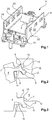
2 einen Ausschnitt eines Gelenks eines Halterahmens in einer offenen Position, -
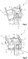
3 einen Ausschnitt eines Gelenks eines Halterahmens in einer geschlossenen Position, -
4 eine perspektivische Darstellung eines offenen Halterahmens, -
5 eine perspektivische Darstellung eines geschlossenen Halterahmens, -
6 eine perspektivische Darstellung eines mit Steckverbindermodulen bestückten Halterahmens und -
7 eine perspektivische Darstellung eines Steckverbindermoduls.
-
1 a perspective view of a holding frame, -
2nd a section of a joint of a holding frame in an open position, -
3rd a section of a joint of a holding frame in a closed position, -
4th a perspective view of an open holding frame, -
5 a perspective view of a closed holding frame, -
6 a perspective view of a holding module equipped with connector modules and -
7 a perspective view of a connector module.
Die Figuren enthalten teilweise vereinfachte, schematische Darstellungen. Zum Teil werden für gleiche, aber gegebenenfalls nicht identische Elemente identische Bezugszeichen verwendet. Verschiedene Ansichten gleicher Elemente könnten unterschiedlich skaliert sein.The figures contain partially simplified, schematic representations. In some cases, identical reference numerals are used for identical but possibly not identical elements. Different views of the same elements could be scaled differently.
Die
Der Halterahmen
In den
Die zweite Hälfte
Jede Stirnseite
Die offene und geschlossene Position wird durch Anschläge im Halterahmen
Die oben erwähnten Anschläge sind jeweils einer Hälfte
Der Halterahmen
Steckverbindermodule
In
In den
Beim dem hier gezeigten Ausführungsbeispiel ist am Halterahmen
Der Kern der Erfindung bezieht sich auf einen Halterahmen
BezugszeichenlisteReference list
- 11
- HalterahmenHolding frame
- 2 , 2'2, 2 '
- GelenkkopfRod end
- 3 , 3'3, 3 '
- GelenkaufnahmeJoint admission
- 44th
- Erste HälfteFirst half
- 55
- Zweite HälfteSecond half
- 6 , 6'6, 6 '
- GelenkarmArticulated arm
- 7 , 7'7, 7 '
- PressnasePress nose
- 88th
- 99
- Erste MuldeFirst hollow
- 10, 10'10, 10 '
- Zweite MuldeSecond trough
- 1111
- StirnseiteFace
- 1212th
- StirnseiteFace
- 1313
- Erster Anschlag (an der zweiten Hälfte)First stop (on the second half)
- 14.14.
- Zweiter Anschlag (an der zweiten Hälfte)Second stop (on the second half)
- 15.15.
- Erster Anschlag (an der ersten Hälfte)First stop (on the first half)
- 16.16.
- Zweiter Anschlag (an der ersten Hälfte)Second stop (on the first half)
- 19.19th
- SteckverbindermodulConnector module
- 20.20th
- HalterungsmittelBracket means
- 21.21.
- RasthakenLocking hook
- 22.22.
- SeitenflächenSide faces
- 23.23.
- AusnehmungRecess
- 24.24th
- ErdungsbuchseGrounding socket
Claims (6)
Priority Applications (15)
| Application Number | Priority Date | Filing Date | Title |
|---|---|---|---|
| DE102015114703.3A DE102015114703B4 (en) | 2015-09-03 | 2015-09-03 | Holding frame for connector modules |
| CN201680051292.9A CN108028491B (en) | 2015-09-03 | 2016-05-30 | Holding frame for a plug-in connector module |
| PL16733872T PL3345257T3 (en) | 2015-09-03 | 2016-05-30 | Support frame for connector module |
| KR1020187008923A KR102067192B1 (en) | 2015-09-03 | 2016-05-30 | Gripping frame for plug connector module |
| RU2018111699A RU2689123C1 (en) | 2015-09-03 | 2016-05-30 | Retaining frame for plug-in connector modules |
| PCT/DE2016/100249 WO2017036439A1 (en) | 2015-09-03 | 2016-05-30 | Holding frame for plug connector modules |
| EP16733872.2A EP3345257B1 (en) | 2015-09-03 | 2016-05-30 | Support frame for connector module |
| US15/755,042 US10276968B2 (en) | 2015-09-03 | 2016-05-30 | Holding frame for plug connector modules |
| PCT/DE2016/100369 WO2017036448A1 (en) | 2015-09-03 | 2016-08-17 | Holding frame for plug connector modules that is fixible in different anglular positions |
| RU2018111328A RU2690030C1 (en) | 2015-09-03 | 2016-08-17 | Holding frame for plug-in modules, fixed in different angular positions |
| CN201680047476.8A CN107925192B (en) | 2015-09-03 | 2016-08-17 | Keep frame |
| PL16765908T PL3345258T3 (en) | 2015-09-03 | 2016-08-17 | Support frame for connector module |
| US15/755,887 US10283900B2 (en) | 2015-09-03 | 2016-08-17 | Holding frame for plug connector modules that is fixable in different angular positions |
| KR1020187008969A KR102095763B1 (en) | 2015-09-03 | 2016-08-17 | Gripping frame for plug connector modules, flexible at different angular positions |
| EP16765908.5A EP3345258B1 (en) | 2015-09-03 | 2016-08-17 | Support frame for connector module |
Applications Claiming Priority (1)
| Application Number | Priority Date | Filing Date | Title |
|---|---|---|---|
| DE102015114703.3A DE102015114703B4 (en) | 2015-09-03 | 2015-09-03 | Holding frame for connector modules |
Publications (2)
| Publication Number | Publication Date |
|---|---|
| DE102015114703A1 DE102015114703A1 (en) | 2017-03-09 |
| DE102015114703B4 true DE102015114703B4 (en) | 2020-03-26 |
Family
ID=56925929
Family Applications (1)
| Application Number | Title | Priority Date | Filing Date |
|---|---|---|---|
| DE102015114703.3A Expired - Fee Related DE102015114703B4 (en) | 2015-09-03 | 2015-09-03 | Holding frame for connector modules |
Country Status (8)
| Country | Link |
|---|---|
| US (1) | US10283900B2 (en) |
| EP (1) | EP3345258B1 (en) |
| KR (1) | KR102095763B1 (en) |
| CN (1) | CN107925192B (en) |
| DE (1) | DE102015114703B4 (en) |
| PL (1) | PL3345258T3 (en) |
| RU (1) | RU2690030C1 (en) |
| WO (1) | WO2017036448A1 (en) |
Families Citing this family (26)
| Publication number | Priority date | Publication date | Assignee | Title |
|---|---|---|---|---|
| DE102015114700B4 (en) | 2015-09-03 | 2020-08-06 | Harting Electric Gmbh & Co. Kg | Holding frame |
| DE102015114701B4 (en) | 2015-09-03 | 2019-01-31 | Harting Electric Gmbh & Co. Kg | Holding frame with blocking element |
| DE102015114696B4 (en) | 2015-09-03 | 2020-10-29 | Harting Electric Gmbh & Co. Kg | Holding frame for connector modules |
| DE102015114699A1 (en) | 2015-09-03 | 2017-03-09 | Harting Electric Gmbh & Co. Kg | Holding frame for connector modules |
| DE102015114697B4 (en) | 2015-09-03 | 2020-03-26 | Harting Electric Gmbh & Co. Kg | Holding frame for connector modules |
| PL3345257T3 (en) | 2015-09-03 | 2021-03-08 | Harting Electric Gmbh & Co. Kg | Support frame for connector module |
| DE102016100794B4 (en) * | 2016-01-19 | 2019-03-28 | Harting Electric Gmbh & Co. Kg | Support frame with guide element for connector modules and system consisting of two of these support frames |
| DE102016213286A1 (en) | 2016-07-20 | 2018-01-25 | Harting Electric Gmbh & Co. Kg | Multi-part holding frame, assembly and assembly process |
| DE102016213251A1 (en) * | 2016-07-20 | 2018-01-25 | Harting Electric Gmbh & Co. Kg | Holding frame arrangement with base frame and fixing element and assembly process |
| USD856385S1 (en) * | 2016-10-19 | 2019-08-13 | Harting Electric Gmbh & Co. Kg | Hood connector |
| DE102017108433B4 (en) | 2017-04-20 | 2021-09-30 | Harting Electric Gmbh & Co. Kg | Holding frame for a connector and assembly method |
| DE102017108432A1 (en) | 2017-04-20 | 2018-10-25 | Harting Electric Gmbh & Co. Kg | Holding frame for a connector and method of assembly |
| EP3622586B1 (en) | 2017-05-12 | 2022-07-06 | HARTING Electric GmbH & Co. KG | Plug connector module |
| BE1025553B1 (en) * | 2017-08-16 | 2019-04-09 | Phoenix Contact Gmbh & Co. Kg | Assembly of a connector part with a support frame and attachable modular contact inserts |
| DE102017124632A1 (en) | 2017-10-23 | 2019-04-25 | Harting Electric Gmbh & Co. Kg | Holding frame for an industrial connector |
| DE102017125859A1 (en) | 2017-11-06 | 2019-05-09 | Harting Electric Gmbh & Co. Kg | Modular mounting frame for connectors |
| DE102018101381A1 (en) | 2018-01-23 | 2019-07-25 | Harting Electric Gmbh & Co. Kg | Connector with spring contact |
| DE102018101790A1 (en) | 2018-01-26 | 2019-08-01 | Harting Electric Gmbh & Co. Kg | sealing insert |
| DE102018108968A1 (en) | 2018-04-16 | 2019-10-17 | Harting Electric Gmbh & Co. Kg | Shielded connector module for a modular industrial connector |
| DE102018115371A1 (en) * | 2018-06-26 | 2020-01-02 | Harting Electric Gmbh & Co. Kg | Connector module for an industrial connector |
| DE102019103562A1 (en) * | 2019-02-13 | 2020-08-13 | Harting Electric Gmbh & Co. Kg | Module frame |
| DE102019125856A1 (en) | 2019-09-25 | 2021-03-25 | Harting Electric Gmbh & Co. Kg | Variable connector module for a modular industrial connector |
| CN113381228A (en) | 2020-02-24 | 2021-09-10 | 菲尼克斯亚太电气(南京)有限公司 | Fixing support of modular insertion core, connector and mounting method of connector |
| DE102020107725B3 (en) | 2020-03-20 | 2021-05-27 | Harting Electric Gmbh & Co. Kg | Shielded connector module |
| DE102021126400A1 (en) | 2021-10-12 | 2023-04-13 | Harting Electric Stiftung & Co. Kg | Connector module and method of manufacture |
| DE102022107244A1 (en) | 2022-03-28 | 2023-09-28 | Harting Electric Stiftung & Co. Kg | Grounding module for inclusion in a metal connector modular frame and for grounding the same |
Citations (3)
| Publication number | Priority date | Publication date | Assignee | Title |
|---|---|---|---|---|
| CN201656162U (en) * | 2010-03-31 | 2010-11-24 | 厦门唯恩电气有限公司 | Fixing frame for connector |
| DE202012103360U1 (en) * | 2011-10-13 | 2013-01-15 | Weidmüller Interface GmbH & Co. KG | Holding frame for connectors |
| CN204205152U (en) * | 2014-10-20 | 2015-03-11 | 宁波欧科瑞连接器有限公司 | A kind of heavy-duty connector rotary self-locking fixed frame |
Family Cites Families (46)
| Publication number | Priority date | Publication date | Assignee | Title |
|---|---|---|---|---|
| US3160280A (en) | 1963-08-12 | 1964-12-08 | Gen Electric | Device for mounting apparatus |
| FR2148699A5 (en) | 1971-07-30 | 1973-03-23 | Socapex | |
| US4693440A (en) | 1986-07-07 | 1987-09-15 | Albert Lalonde | Refreshment cup holder |
| US5529426A (en) | 1991-10-24 | 1996-06-25 | Yazaki Corporation | Housing block-retaining construction |
| JP3147221B2 (en) | 1996-02-28 | 2001-03-19 | 矢崎総業株式会社 | Movable connection structure |
| JP3235489B2 (en) | 1996-11-14 | 2001-12-04 | 住友電装株式会社 | Block connector |
| DE19707120C1 (en) * | 1997-02-22 | 1998-06-25 | Harting Kgaa | Mounting frame for plug-in connector modules |
| DE19745384B4 (en) | 1997-10-14 | 2005-06-30 | The Whitaker Corp., Wilmington | Electrical connector assembly |
| US6196869B1 (en) | 1998-10-30 | 2001-03-06 | Lucent Technologies Inc. | Mounting bracket and power bus for a connector block |
| US6350141B1 (en) | 2000-05-30 | 2002-02-26 | Fci Americas Technology, Inc. | Connector frame for a high density electrical connector |
| US6692310B2 (en) | 2001-11-01 | 2004-02-17 | Molex Incorporated | Modular system for stacking electrical connector assemblies |
| DE20217273U1 (en) | 2002-11-09 | 2003-01-16 | Harting Electric Gmbh & Co Kg | Fastening device for connectors |
| TWM244598U (en) | 2003-09-26 | 2004-09-21 | Molex Taiwan Ltd | SIM card connector |
| US7056138B2 (en) | 2004-08-05 | 2006-06-06 | Tellabs Petaluma, Inc. | Retaining clip for Anderson-type power connectors |
| DE202005020026U1 (en) | 2005-12-22 | 2006-03-16 | Harting Electric Gmbh & Co. Kg | Holding frame for plug-in modules |
| JP4716123B2 (en) | 2006-06-16 | 2011-07-06 | 住友電装株式会社 | Connector cap holding structure |
| UA29986U (en) * | 2007-04-04 | 2008-02-11 | Общество С Дополнительной Ответственнолстью "Павеж" | Switchboard panel |
| DE102007040496A1 (en) | 2007-08-21 | 2009-02-26 | Telegärtner Karl Gärtner GmbH | Cable connection device and connection device with such cable processing devices |
| JP5346530B2 (en) * | 2008-09-24 | 2013-11-20 | 株式会社三桂製作所 | Holding frame for connector module |
| CN101764314B (en) | 2008-12-23 | 2012-10-31 | 富士康(昆山)电脑接插件有限公司 | Electric connector |
| PL2510590T3 (en) | 2009-12-09 | 2014-10-31 | Harting Electric Gmbh & Co Kg | System plug connector having an adapter module |
| ES2589914T3 (en) | 2009-12-09 | 2016-11-17 | Harting Electric Gmbh & Co. Kg | Plug-in connector for systems |
| DE202010002396U1 (en) | 2010-02-16 | 2010-05-20 | Harting Electric Gmbh & Co. Kg | Electrical connector with locking bracket |
| CN201656115U (en) * | 2010-03-18 | 2010-11-24 | 厦门德利兴电气设备有限公司 | Positioning device for connector module |
| US8449314B1 (en) | 2010-12-22 | 2013-05-28 | Omnetics Connector Corporation | Latching system for electrical connector |
| CN202084755U (en) * | 2011-04-28 | 2011-12-21 | 中航光电科技股份有限公司 | Connector module structure and fixed frame thereof |
| CN202352910U (en) | 2011-12-15 | 2012-07-25 | 四川华丰企业集团有限公司 | Novel rectangle movable frame used for heavy load connector |
| DE102012110907B4 (en) | 2012-11-13 | 2019-06-13 | Harting Electric Gmbh & Co. Kg | Holding frame for holding connector modules |
| US8777676B1 (en) | 2012-12-21 | 2014-07-15 | Hubbell Incorporated | Universal mount contact block with reversible protected wiring terminals |
| US8821186B2 (en) | 2013-01-14 | 2014-09-02 | Cheng Uei Precision Industry Co., Ltd. | Universal serial bus connector |
| ITMI20130462A1 (en) | 2013-03-27 | 2014-09-28 | Westec S R L | STRUCTURE OF SUPPORTING FRAME FOR MODULAR CONNECTORS. |
| DE102013106279A1 (en) | 2013-06-17 | 2014-12-18 | Harting Electric Gmbh & Co. Kg | Holding frame for connector modules |
| DE202013103611U1 (en) | 2013-08-12 | 2013-09-19 | Harting Electric Gmbh & Co. Kg | Holding frame for connectors |
| CN106463877B (en) | 2014-04-02 | 2019-01-22 | 哈廷电子有限公司及两合公司 | Plug-in connector system |
| CN104466562B (en) | 2014-12-10 | 2017-07-21 | 资阳中车电气科技有限公司 | Connector modules fixed frame |
| CN204271392U (en) | 2014-12-10 | 2015-04-15 | 资阳南车电气有限公司 | Connector modules fixed frame |
| DE102015101433B3 (en) | 2015-02-02 | 2016-06-16 | Harting Electric Gmbh & Co. Kg | Holding frame for connector modules |
| DE102015114696B4 (en) | 2015-09-03 | 2020-10-29 | Harting Electric Gmbh & Co. Kg | Holding frame for connector modules |
| DE102015114701B4 (en) | 2015-09-03 | 2019-01-31 | Harting Electric Gmbh & Co. Kg | Holding frame with blocking element |
| DE102015114699A1 (en) | 2015-09-03 | 2017-03-09 | Harting Electric Gmbh & Co. Kg | Holding frame for connector modules |
| PL3345257T3 (en) | 2015-09-03 | 2021-03-08 | Harting Electric Gmbh & Co. Kg | Support frame for connector module |
| DE102015216929A1 (en) * | 2015-09-03 | 2017-03-09 | Harting Electric Gmbh & Co. Kg | Holding frame for holding connector modules |
| DE102015114700B4 (en) | 2015-09-03 | 2020-08-06 | Harting Electric Gmbh & Co. Kg | Holding frame |
| DE102015114702B4 (en) | 2015-09-03 | 2019-01-31 | Harting Electric Gmbh & Co. Kg | holding frame |
| DE102015114697B4 (en) | 2015-09-03 | 2020-03-26 | Harting Electric Gmbh & Co. Kg | Holding frame for connector modules |
| DE102015114698A1 (en) | 2015-09-03 | 2017-03-30 | Harting Electric Gmbh & Co. Kg | Holding frame for connector modules |
-
2015
- 2015-09-03 DE DE102015114703.3A patent/DE102015114703B4/en not_active Expired - Fee Related
-
2016
- 2016-08-17 EP EP16765908.5A patent/EP3345258B1/en active Active
- 2016-08-17 KR KR1020187008969A patent/KR102095763B1/en active IP Right Grant
- 2016-08-17 RU RU2018111328A patent/RU2690030C1/en active
- 2016-08-17 CN CN201680047476.8A patent/CN107925192B/en active Active
- 2016-08-17 PL PL16765908T patent/PL3345258T3/en unknown
- 2016-08-17 WO PCT/DE2016/100369 patent/WO2017036448A1/en active Application Filing
- 2016-08-17 US US15/755,887 patent/US10283900B2/en active Active
Patent Citations (3)
| Publication number | Priority date | Publication date | Assignee | Title |
|---|---|---|---|---|
| CN201656162U (en) * | 2010-03-31 | 2010-11-24 | 厦门唯恩电气有限公司 | Fixing frame for connector |
| DE202012103360U1 (en) * | 2011-10-13 | 2013-01-15 | Weidmüller Interface GmbH & Co. KG | Holding frame for connectors |
| CN204205152U (en) * | 2014-10-20 | 2015-03-11 | 宁波欧科瑞连接器有限公司 | A kind of heavy-duty connector rotary self-locking fixed frame |
Also Published As
| Publication number | Publication date |
|---|---|
| US20180254578A1 (en) | 2018-09-06 |
| EP3345258A1 (en) | 2018-07-11 |
| RU2690030C1 (en) | 2019-05-30 |
| KR20180048876A (en) | 2018-05-10 |
| EP3345258B1 (en) | 2019-12-25 |
| KR102095763B1 (en) | 2020-04-02 |
| CN107925192A (en) | 2018-04-17 |
| DE102015114703A1 (en) | 2017-03-09 |
| PL3345258T3 (en) | 2020-06-29 |
| US10283900B2 (en) | 2019-05-07 |
| WO2017036448A1 (en) | 2017-03-09 |
| CN107925192B (en) | 2019-09-17 |
Similar Documents
| Publication | Publication Date | Title |
|---|---|---|
| DE102015114703B4 (en) | Holding frame for connector modules | |
| DE102015114696B4 (en) | Holding frame for connector modules | |
| EP3345257B1 (en) | Support frame for connector module | |
| DE102015114697B4 (en) | Holding frame for connector modules | |
| EP3345251B1 (en) | Fixing frame for connector with a blade shaped fixing means | |
| EP3345253B1 (en) | Holding frame with restoring force for plug connector modules | |
| DE102015114700B4 (en) | Holding frame | |
| EP3345252B1 (en) | Holding frame comprising a fixing element held in a movable manner | |
| DE102015222561B4 (en) | Holding frame for holding connector modules | |
| WO2020207529A1 (en) | Arrangement of modular plug connectors for a printed circuit board | |
| EP3406002B1 (en) | Holding frame with a guiding element for plug connector modules | |
| DE102014110279B3 (en) | Connectors | |
| DE60131217T2 (en) | Electrical spring connection | |
| WO2017190824A1 (en) | Coupling device | |
| DE102017111293A1 (en) | pin | |
| EP3602697A1 (en) | Mounting frame comprising a pe contact | |
| EP3577725A1 (en) | Plug with protective conductor bridge | |
| DE202022100801U1 (en) | clamp crimping pliers | |
| DE202013103753U1 (en) | Connector arrangement with coding element | |
| DE2853512C3 (en) | ||
| DE1590380C (en) | One-piece clamp | |
| DE102015116818A1 (en) | Connecting device and method for producing an electrically conductive connection between an electrical conductor and a technical device | |
| CH712593A2 (en) | Triple socket and equipped power supply group. | |
| DE1817075B2 (en) | Busbar and cable connector - connects at least two conductors using U-shaped straps and screw plate |
Legal Events
| Date | Code | Title | Description |
|---|---|---|---|
| R012 | Request for examination validly filed | ||
| R016 | Response to examination communication | ||
| R016 | Response to examination communication | ||
| R018 | Grant decision by examination section/examining division | ||
| R020 | Patent grant now final | ||
| R119 | Application deemed withdrawn, or ip right lapsed, due to non-payment of renewal fee |